


User Manual
MODEL QS408
H.264 NETWORK DVR
QS Series
MODEL QS206
1

Thank You for Choosing a Q-See Product!
All of our products are backed by a conditional service warranty covering all hardware for 12
months from the date of purchase. Additionally, our products also come with a free exchange
policy that covers all manufacturing defects for one month from the date of purchase.
Permanent upgrading service is provided for the software and is available at www.Q-See.com.
Be certain to make the most of your warranty by completing the registration form online. In
addition to warranty and technical support benefits, you’ll receive notifications of product
updates along with free downloadable firmware updates for your DVR. Register today at
www.Q-See.com!
Please see the back of this manual for exclusions.
© 2011 Q-See. Reproduction in whole or in part without written permission is prohibited. All
rights reserved. This manual and software and hardware described herein, in whole or in part,
may not be reproduced, translated, or reduced to any machine-readable form without prior
written approval.
Trademarks: All brand names and products are trademarks or registered trademarks of their
respective owners.
Q-See is a registered trademark of DPS, Inc.
Disclaimer: The information in this document is subject to change without notice. The
manufacturer makes no representations or warranties, either express or implied, of any kind
with respect to completeness of its contents.
Manufacturer shall not be liable for any damages whatsoever from misuse of this product.
2

About this Manual
This manual is written for the QS206 DVR and was accurate at the time it was completed.
However, because of our ongoing effort to constantly improve our products, additional
features and functions may have been added since that time and on-screen displays may
change. We encourage you to visit our website at www.Q-see.com to check for the latest
firmware updates and product announcements.
Throughout the manual we have highlighted warnings and other important information that will
assist you in operating your new system in a safe and trouble-free manner. Please take the
time to read and follow all instructions and pay attention to alerts as shown below:
IMPORTANT! Red boxes with this icon indicate warnings. To prevent
possible injury or damage to the product, read all warnings before use.
NOTE! Text in blue boxes with the Information icon offer additional guidance
and explanations about how to make the most out of your system.
Rev. 1.2 3/21/11
3

TABLE OF CONTENTS
1. INTRODUCTION 7
2. INSTALLATION AND CONNECTION 10
QS206 10
QS408 12
3. CONTROLS 14
3.1 Mouse Control 14
Virtual Keyboard 15
3.2 Remote Control 16
4. BASIC OPERATION 19
4.1 Power On/Off 19
Standby Mode 19
Shutdown 19
4.2 Shortcut Menu 19
4.3 System Login 20
4.4 Main Menu 20
4.5 Basic Settings 21
Language 21
Date/Time 22
Password 23
Display 24
Video/Audio 25
4.6 Hard Drive (HDD) Management 26
Formatting the Internal Hard Drive 26
4.7 PLAYBACK 27
Video Search 27
Using the On-Screen Playback Controls 28
File List 28
4.8 Backup 30
Using the Playback Software 31
5. RECORDING 34
5.1 Recording Configuration 34
5.2 Recording Schedule 35
5.3 Mask Field 36
5.4 Motion Detect 37
4

6. ADVANCED FEATURES 38
6.1 Alarm 39
6.2 Email Setup 40
6.3 System Info 41
6.4 System 41
Restoring Factory Settings 42
Restarting the DVR (Soft-Reset) 42
Upgrading the Firmware 42
6.5 Pan-Tilt-Zoom Cameras (PTZ) 43
7. REMOTE ACCESS 44
7.1 Network Setup 44
DHCP 44
UPNP 45
Static IP 48
PPPOE 49
7.2 Port Forwarding 50
Part 1: Determine the IP Address of the DVR 50
Part 2: Determine the Number of Routers on the Network 51
Part 3: Download the Simple Port Forwarding Program 53
Part 4: Setting Up DMZ in Router 2 58
7.3 DDNS (Dynamic Domain Name Service) 59
7.4 Accessing your DVR remotely 61
Accessing the DVR Using Internet Explorer 61
7.5 Remote Surveillance Software 66
Logging In Remotely 66
The Live View Window 67
Recording 68
PTZ Control 69
Screen Captures 69
Playback 70
Search 71
Remote Backup 72
Remote Setup 73
7.6 Mobile Surveillance 75
8. HARD DRIVE INSTALLATION 76
5

APPENDIX 77
Product Specifications 77
Basic Operational Specifications 78
Frequently Asked Questions 79
Q-SEE PRODUCT WARRANTY 83
Questions or Comments? Contact Us 84
6

INTRODUCTION
To prevent damage to your Q-See product or injury to yourself or to others, read and
understand the following safety precautions in their entirety before installing or using this
equipment. Keep these safety instructions where all those who use the product will read them.
CHAPTER 1
WARNING! ELECTRIC SHOCK RISK!
nCheck the unit and any accessories included in the package immediately after opening. If
items are missing or damaged, repackage and return to the point of purchase.
n
Use the proper power source. Only use the power adapter supplied with your system. Do
not use this product with a power source that applies more than the specified voltage (100240V AC).
nNever insert anything metallic into the DVR. Inserting anything into the DVR or its case can
be a source of dangerous electric shock.
nDo not operate in dusty areas.
nDo not expose this product to rain or use near water. If this product accidentally gets wet,
unplug it and contact an authorized dealer immediately.
nKeep product surfaces clean and dry. To clean the outside case of the DVR, gently wipe
using a lightly dampened cloth (only use water, do not use solvents).
nDo not operate this DVR without the cover securely in place. Do not attempt to do any
repairs to the DVR yourself. If there are unusual sounds or smells coming from the DVR,
unplug it immediately and contact Q-See technical support. Under no circumstances
should the cover be removed while the device is connected to a power source. You should
only remove the cover to install/replace the hard disk drive (See Chapter 8) or replace the
standard 3v lithium cell battery on the motherboard. These are the only user serviceable
parts. You may need to replace the battery if the internal clock resets itself after a power
outage
nHandle DVR box carefully. If you accidentally drop your DVR on any hard surface, it may
cause a malfunction. If the DVR doesn’t work properly due to physical damage, contact an
authorized dealer for repair or exchange.
nMake sure there is proper air circulation around the unit. This DVR system uses a hard drive
for video storage which generates heat during operation. Do not block air holes located on
the bottom, top, sides and back of the DVR as they are designed to keep the system cool
while running. Install or place this product in an area where there is ample air circulation.
nProvide proper ventilation. This DVR has a built-in fan that properly ventilates the system.
Do not cover or impede this fan.
7

FEATURES AND SPECIFICATIONS
This product offers the following features:
Smartphone Compatible
Access live footage directly from your iPhone, iPad or smartphones running Windows Mobiel,
Android, Symbian or BlackBerry operating systems. Your DVR can also be set to e-mail your
hand held-device whenever specific activity occurs, such as motion detection.
View Your Video Feed Online with No Extra Service Fees
View your DVR’s live or recorded video footage on any Internet accessible computer with
Internet Explorer, Mozilla Firefox and Google Chrome (using IE plug-in).
Stay Notified with Customizable Email Alerts
Set your system up to notify you when an event has occurred at the location you are
monitoring. Notification alerts can easily be adjusted to your specifications.
Advanced Motion Detection Activated Recording
Advanced motion detection settings ensure that false alarms are not triggered. The easy to
use motion detect set up screen allows you to mask out certain areas which experience heavy
movement in order to avoid false alarms and avoid unnecessary record triggering.
Multiple Backup Options
A built-in USB port gives you the option of backing up and transferring your video footage
using a flash drive or external USB hard drive. You can also connect to an external CD/
DVD writer to burn your file footage right onto a compact disc or DVD disc. Files can also be
accessed from your DVR system to a remote computer location by logging on remotely.
Connect to a TV or PC Monitor Easily
This system comes with both a VGA and BNC out port to allow you to connect to a TV or
computer monitor for viewing purposes.
User-Friendly LCD Control Functions
Front panel button control allows instant booting up and system standby at the press of a
button. LCD monitor can be set to go into energy efficient stand-by mode.
Included Mouse and Remote Control
In addition to front panel button controls, system can also be booted up and system standby
using the included remote control or mouse. Mouse operation function supports intelligent
operation by enabling copy and paste functions.
Storage Function
Encrypted file format to ensure data security and avoid vicious data modification.
Compression Format
Supports multiple-channel audio and video. Independent hardware decodes the audio and
video signal from each channel to maintain video and audio synchronization.
8

Audio Recording
Two channels include audio as well as video input.
24/7 Scheduled Recording
Choose which days of the week and hours of the day you want to set your DVR to record or
not record.
Multiple Playback Options and Advanced Search Functions
Supports real-time recording on each channel independently. Search through recorded files
while you are playing live footage, monitoring through a remote location using a supported
internet browsing application and backing up system files. A variety of playback modes
include: slow play, fast play, backward play and frame by frame play.
Network Monitoring
Supports network remote real-time monitoring (available bandwidth permitting), remote record
search and remote PTZ control.
Alarm Activation Function
Several relay alarm outputs enable you to pair your system with an on-site alarm system.
Communication Ports
s RS485 port can be used for PTZ camera control.
s RS232 port can connect to a keyboard for central control, and can also connect to PC
COM to upgrade system and maintain system settings.
s Standard Ethernet port allows you to access the DVR from a network or the Internet.
PTZ camera control
s Supports PTZ decoder via RS485.
s Supports a variety of protocols to allow the DVR to control the PTZ speed dome: AD1641M,
Admatrix, Banknote, DH-CC440, DH-Matrix, DH-SDI, Dh-SD2, Eptz, General, Haiyu, Hy, Lilin,
Mercer-1, Panasonic, PE5051K, Pelco-9750, PelcoASCII, PelcoD, Pelcod-DON, PelcoD-S,
Pelco-SI, Pelco-T, PelcoD1, PelcoD1-T, PelcoP, PelcoP-HK, PelcoP1, PelcoP5, Philips,
Pih-717, QT-2XXD, Rm110a, Sae, Samsung, Sanli, Santachi, Sharp, Sony, WV-CS850I,
WV-CS850II, WV-CS950, Yaan
NOTE! Depending on your point of purchase, your DVR may have the hard
disk drive already installed. If your drive was packaged separately, or if you
wish to upgrade your installed drive up to a 2TB drive, please see Chapter 10
at the back of this manual which covers installing the drive.
9
INSTALLATION AND
CHAPTER 2
CONNECTION
Please note that it is important to keep in mind common safety guidelines when installing your
DVR or connecting additional devices – including turning off and unplugging your DVR before
installing internal components.
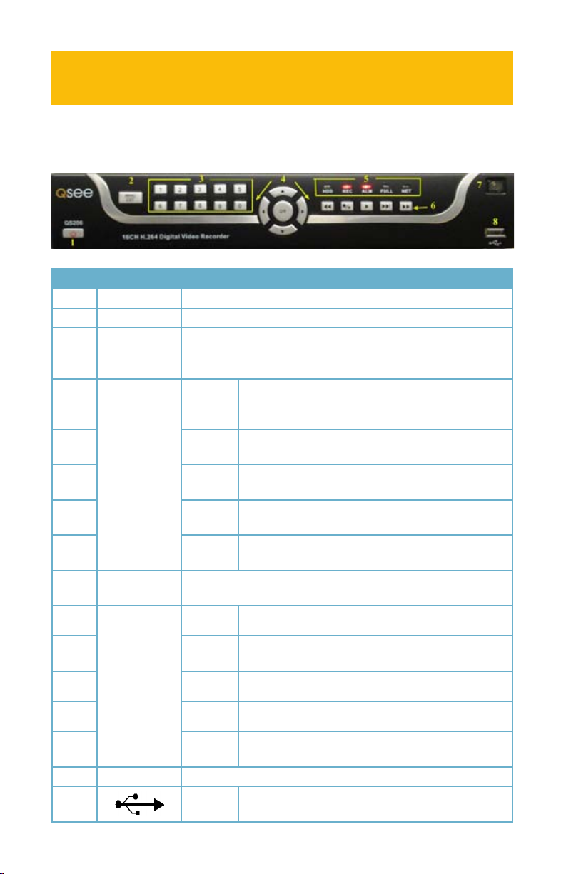
QS206
PICTURE 2-1
Item # Name/ Symbol Description
1 STANDBY Press to set the system in standby mode.
2 MENU/EXIT Press to open/close the main menu.
3 CHANNEL/
NUMBERS/
PLAYBACK
4 NAVIGATION/OKOK In menus, press to confirm selections; in PTZ mode,
5 LED
INDICATORS
6 DURING
PLAYBACK
PRESS:
7 IR SENSOR IR Receiver for remote control.
8
Press buttons 1-8 to view the selected channel full-screen; press
buttons 1-0 to input passwords and user IDs.
press to change the navigation buttons to control a
connected PTZ camera (not included)
▲
▼
◄
►
Shows status of hard drive, recording, alarm, HDD full and
network.
◄ ◄
n/►
►
► ►
► ►
USB Connect a USB flash drive for data backup and
Press to move cursor up; in PTZ mode, press to pan
camera up.
Press to move cursor down; in PTZ mode, press to
pan camera down.
Press to move cursor left; in PTZ mode, press to pan
camera left.
Press to move cursor right; in PTZ mode, press to
pan camera right.
Increase reverse playback speed 1X, 2X, 4X.
Press to freeze playback to one frame, then press
again to advance frame-by-frame.
Press to start playback
Press to slow playback speed by 1/2, 1/4, 1/8.
|
Press to increase forward playback speed 1X, 2X,
4X.
firmware upgrades
10

PICTURE 2-2
Item #Physical
Connector
1 VIDEO IN Video input for connecting analog video signal input (BNC)
2
3 VGA OUTPUT To connect to VGA monitor
4 NETWORK For connecting Ethernet cable
5 USB Mouse port
ALARM INPUT 8 I/O Alarm input
ALARM
OUTPUT
6
7 AUDIO IN Audio input for connecting audio signal (2 feeds)
8
9 VIDEO OUT
RS485 RS485 for connecting PTZ
RS232 Debugging port
+12V
AUDIO
OUTPUT
IMPORTANT! The default resolution of this DVR is 1024 x 768 pixels. Some
monitors smaller than 19” may not display video properly.
Description
DC 12V/3A Power Connection
I/O Output for alarm
Power supply for DC relay, the current is 100MA (to prevent
short circuits)
For connection to amplified speaker
Video output for connecting TV (BNC)
Power
The DVR’s power supply plugs into the socket marked DC 12V next to power switch (Item
number 2 in Picture 2-2). It is absolutely essential that you only use the power supply that
came with the DVR to ensure proper operation and to avoid damage.
We also recommend that you use an uninterrupted power supply (UPS) so that the system will
continue to operate in the event of a power loss. In addition, you should connect the DVR into
a UL-1449 rated surge protector. It should have a joule rating of at least 400, a response time
of 10 nanoseconds or less and a clamping voltage of no more than 330 volts.
Mouse
The included USB mouse will only operate if connected to the DVR through the USB port
on the rear of the DVR (Item number 5 in Picture 2-2). The USB port on the front of the
DVR’s screen is only for external USB storage devices.
11

QS408
Item # Name/ Symbol Description
1 STANDBY Press to set the system in standby mode.
2 IR SENSOR IR Receiver for remote control.
3 LED Inicators Shows status of hard drive, recording, alarm, HDD full and
network.
4 CHANNEL/
NUMBERS/
PLAYBACK
5 MENU/EXIT Press to open/close the main menu.
4 NAVIGATION/OKOK In menus, press to confirm selections; in PTZ mode,
8
6 DURING
PLAYBACK
PRESS:
Press buttons 1-8 to view the selected channel full-screen; press
buttons 1-0 to input passwords and user IDs.
press to change the navigation buttons to control a
connected PTZ camera (not included)
▲
▼
◄
►
USB Connect a USB flash drive for data backup and
◄ ◄
n/►
►
► ►
► ►
Press to move cursor up; in PTZ mode, press to pan
camera up.
Press to move cursor down; in PTZ mode, press to
pan camera down.
Press to move cursor left; in PTZ mode, press to pan
camera left.
Press to move cursor right; in PTZ mode, press to
pan camera right.
firmware upgrades
Increase reverse playback speed 1X, 2X, 4X.
Press to freeze playback to one frame, then press
again to advance frame-by-frame.
Press to start playback
Press to slow playback speed by 1/2, 1/4, 1/8.
|
Press to increase forward playback speed 1X, 2X,
4X.
12

Item #Physical
Connector
Description
1
2 VIDEO OUT
3 VIDEO IN Video input for connecting analog video signal input (BNC)
4 AUDIO IN Audio input for connecting audio signal (2 feeds)
ALARM INPUT 8 I/O Alarm input
ALARM
OUTPUT
5
6 NETWORK For connecting Ethernet cable
7 VGA OUTPUT To connect to VGA monitor
8
9 USB Mouse port
10 Power Switch Power On/Off
RS485 RS485 for connecting PTZ
RS232 Debugging port
+12V
AUDIO
OUTPUT
IMPORTANT! The default resolution of this DVR is 1024 x 768 pixels. Some
monitors smaller than 19” may not display video properly.
DC 12V/3A Power Connection
Video output for connecting TV (BNC)
I/O Output for alarm
Power supply for DC relay, the current is 100MA (to prevent
short circuits)
For connection to amplified speaker
13

CONTROLS
This DVR can be controlled through the USB mouse, the remote control or by using the
buttons on the front of the device. For the purposes of this manual, instructions will be given
for using the mouse but the other modes are also presented in this chapter.
CHAPTER 3
3.1 MOUSE CONTROL
The mouse operates in a manner similar to how it is used on a conventional computer; pointand-click, right-click, double click and so on. How these functions are used is based on the
context of where they are used. Some examples are:
LEFT CLICK: Selecting an item
Opening a menu
Checking a box or motion detection status
Selecting letters, numbers or symbols on the virtual keyboard.
DOUBLE CLICK: Selecting an event for playback
Selecting a screen to zoom into from multi-screen mode
RIGHT CLICK
Opens Pop-Up
CLICK-AND-DRAG Select motion detection zone
Select privacy mask zone
Exits any window. Exits
any menu or reopens
previous menu.
Shortcut Menu
M A I N M E N U
M U L T I P I C T U R E
P T Z
V I D E O S E A R C H
M U T E
S T A R T R E C O R D
S T O P R E C O R D
S T A R T C R U I S E
S T A N D B Y
V I D E O S E Q U E N C E
PICTURE 3-1
14
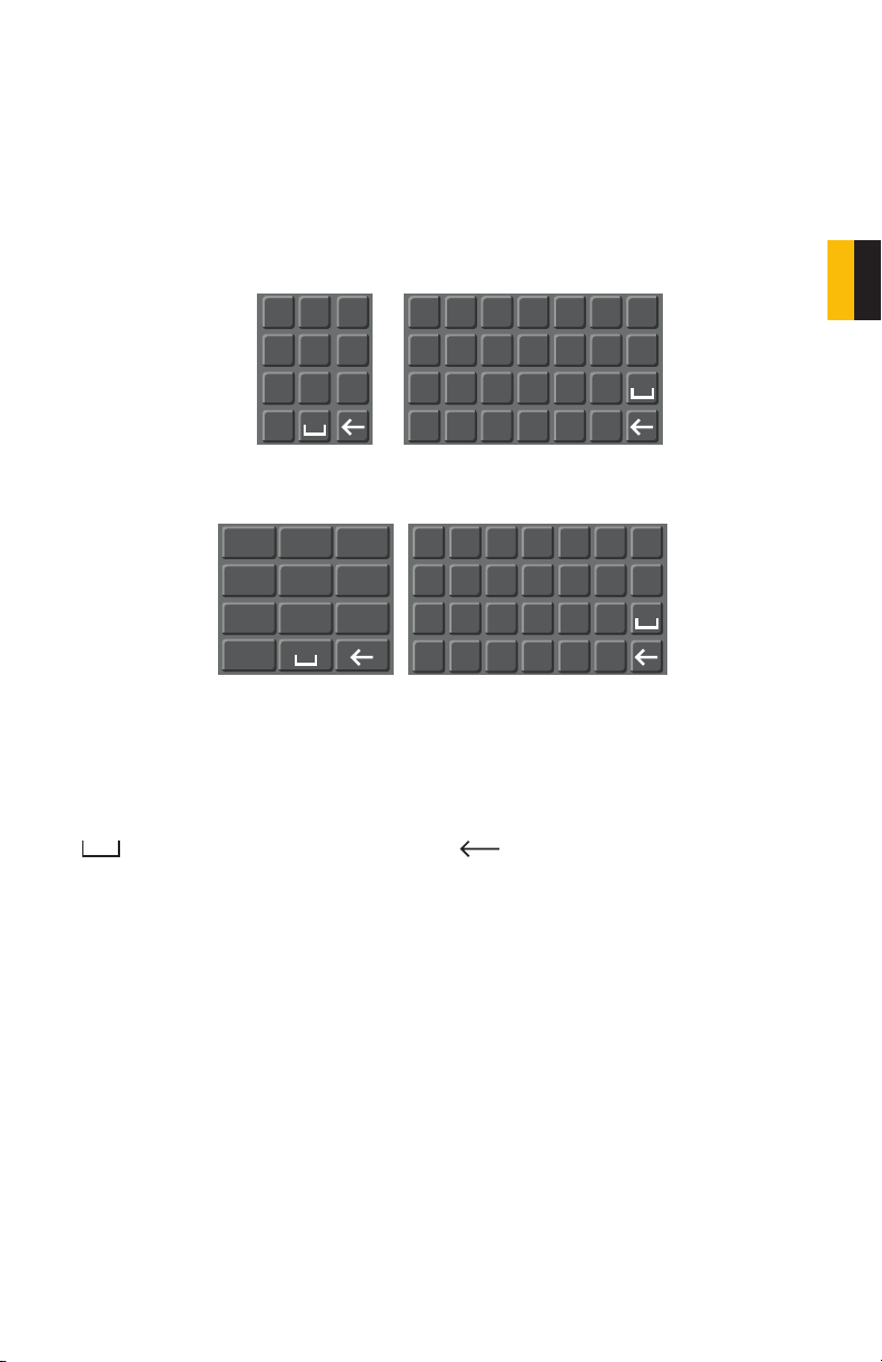
VIRTUAL KEYBOARD
The virtual keyboard is contextual. For example, it will only show digits when the field is for
numeral entries. In fields where letters and symbols can be entered, users can switch between
various formats – numbers, upper case, lower case and symbols – by selecting the white
keyboard symbol that will appear to the right of a field where text can be entered. The symbol
itself will change to show which keyboard format is available next.
Available keyboards include:
CHAPTER 3 CONTROLS
2 3
1
54 6
87 9
0
NUMBERS
1 /
2 :
3 .
4 ?
5 -
6
7 @
8 #
9%
0 &
SYMBOLS
The keyboards are used by clicking on the desired character. Spaces are entered using the
symbol and characters are deleted with the key. Clicking outside of the keyboard
will close it.
a
h
o
u
A
_
H
O
U
PICTURE 3-2
b
c
d
i
j
k
p
q
v
w
x
UPPER CASE
LETTERS
B
C
I
J
P
Q
V
W
LOWER CASE
LETTERS
r
D
K
R
X
e
f
g
l
m
n
s
t
y
z
E
F
G
L
M
N
S
T
Y
Z
15

3.2 REMOTE CONTROL
The buttons on the Remote Control operate in the same manner as on a conventional DVR
remote. Some buttons have multiple functions depending on which menu is being accessed.
# Name/Symbol Function
1 STANDBY Press to turn standby mode ON/OFF.
2 LOGIN/LOCK If “Security” has been enabled in the Setup menu,
press to open the user password login screen.
3 Number/Channel buttons While in menus, press buttons 0~9 to enter values;
during live viewing, press to view channels full-screen.
4
5 MENU Opens the main menu.
6 PTZ Press to open the PTZ control window.
7 EXIT Close menu windows.
8 Navigation/OK:
/CH+
/FWD
/REW
/CH-
OK In menus, press to confirm selections; during
9 +/ - : In menus, press to
adjust values.
10 RECORD: Press to start
manual recording.
11 STOP: Press to stop manual
recording.
12 EXTRA: For future use.
13 Playback controls:
Press to switch between quad and full-screen
displays.
Move cursor in menus up; Channel Up.
Move cursor in menus to the right
Move cursor in menus left
Move cursor in menus down; Channel down.
playback and preview, press to view system
information
Increase reverse playback speed 2X, 4X, 8X
Press to start playback
Press to increase forward playback speed 2X, 4X, 8X
Press to slow playback speed by 1/2, 1/4, 1/8
Press to freeze playback to one frame, then press
again to advance frame-by-frame
16

CHAPTER 3 CONTROLS
TIP: When using the remote
control to enter password and
camera titles, select the field
using the navigation buttons,
press ENTER, and then press
the number buttons.
PICTURE 3-3
17

18

BASIC OPERATION
This chapter is intended to help you get your DVR up and running before you activate any
advanced features which are covered in later chapters. You can use the mouse, remote
control and the buttons on the front of the DVR to operate your system, but for convenience,
we will be discussing operations using the mouse.
CHAPTER 4
4.1 POWER ON/OFF
Connect the power cable to the DC 12V port on the rear panel. At startup, the system
performs a basic system check and runs an initial loading sequence. After a few moments,
the system loads a live display view.
STANDBY MODE
The system can be put into Standby Mode. Power will remain to the system but will not be
recording.
To Start/Stop Standby Mode:
Press and hold the POWER button on the front panel or remote control until the prompt
closes. The system enters standby mode.
Press and hold the POWER button on the front panel or remote control until the system
beeps. The system will begin powering up.
Select “Standby” in the pop-up Shortcut menu (described in the next section)
SHUTDOWN
When the DVR will not be in use for an extended period of time, it is recommended that you
shut it down completely. To do so, follow the above instructions to put the DVR into Standby
mode. Once the DVR has gone into hibernation disconnect it from its power source. Turning
off the surge protector that it is plugged into is the preferred method.
CHAPTER 4 BASIC OPERATION
4.2 SHORTCUT MENU
The Shortcut menu gives direct access to many of the system’s functions, features and
options without having to go through a series of intermediiate steps.
Right-clicking with the mouse anywhere on the screen will bring up the Shortcut menu.
MAIN MENU: Opens the main system menu
MULTIPICTURE: Choose multi-screen mode
PTZ: Opens the PTZ control menu
VIDEO SEARCH: Open the Search Menu to view
recorded video
MUTE: Mute listen-in audio on the system
START RECORD: Start manual recording
STOP RECORD: Stop manual recording
START CRUISE: Activates preset PTZ cruise
STANDBY: Click to go into standby mode
ROTATION: Start full screen cycle through
channels
To close the Shortcut menu, click anywhere on screen.
M A I N M E N U
M U L T I P I C T U R E
P T Z
V I D E O S E A R C H
M U T E
S T A R T R E C O R D
S T O P R E C O R D
S T A R T C R U I S E
S T A N D B Y
V I D E O S E Q U E N C E
PICTURE 4-1
19

4.3 SYSTEM LOGIN
By default, passwords are disabled on the
system. You do not need to enter a password
when accessing any system menus. The
default user name is admin and the
password is blank (no password). Just click
Apply However, for security purposes, it is
highly recommended to enable passwords on
the system using the Password menu.
PICTURE 4-2
4.4 MAIN MENU
To access the Main Menu, right-click anywhere onscreen with the mouse to open the Shortcut menu and select MAIN MENU. Pressing the Menu or MENU/EXIT button on the remote
control or front panel of the DVRm, respectively, will also open the Main Menu.
Placing the mouse over an icon will display
iinformation about its contents and/or
function.
PICTURE 4-3
Symbol Name Function
SEARCH Search for recorded video on the system.
RECORD Configure recording parameters (quality, resolution), set record
modes, and enable/disable audio recording.*
HDD Display hard drive status and format the internal hard drive of the
system.
BASIC Open the Basic Setup Menu, which lets you set the system
language, date and time, Device IDs and passwords, and configure
audio and video settings.
ADVANCE Opens the Advanced Setup Menu, which lets you view system
info, configure alarm, PTZ, mobile, and network settings.
EXIT Closes the Main Menu.
*Audio capable cameras or powered microphones (not included) are required for audio
recording on the system.
20

4.5 BASIC SETTINGS
Set the system language, date and time, passwords, and configure audio and display
options.
The Basic Setup menu contains the following
submenus: Language, Date/Time,
Password, Display, and Video/Audio.
PICTURE 4-4
LANGUAGE
English is the only language available at this
time.
PICTURE 4-5
CHAPTER 4 BASIC OPERATION
IMPORTANT! After changing the Video Format, the device will need to be
restarted.
21

DATE/TIME
IMPORTANT! Date and time should be properly set before continuing so that
you can easily locate recorded events. Inaccurate dates and times on files may
affect their admissibility as evidence.
To set the date and time:
STEP 1. Click DATE/TIME and configure
the following options:
• DATE: Enter the day, month, and year.
• DATE FORMAT: Select DD/MM/YYYY,
MM/DD/YYYY, or YYYY/MM/DD
• TIME: Enter the time
• TIME FORMAT: Use the drop-down
menu and select 12 HOURS or 24
HOURS
• DST: Use the drop-down menu to
select ON/OFF to enable/disable
Daylight Savings Time
• ZONE: Select the correct time zone based on your current location. If you are uncertain
of your time zone, you can find it at http://www.worldtimezone.com
STEP 2. Click MODIFY DATE AND TIME. Click CLOSE in the confirmation window.
STEP 3. Click APPLY. The new date and time are saved.
PICTURE 4-6
Daylight Savings Time
To set daylight savings time:
STEP 1. Under DST, select ON. DST options appear.
STEP 2. Under DST MODE select one of the following:
• CUSTOM: Set customized start and end times for DST (go to step 4)
• DEFAULT: The Default setting will apply DST from the second Sunday of March to the
second Sunday in November (Go to step 3)
• If using the DEFAULT, click APPLY.
• If setting a CUSTOM DST, use the drop-down menus to select a week and month for
the start and end times.
STEP 3. Click APPLY. Click CLOSE in the confirmation window.
STEP 4. Click EXIT in each menu until all windows are closed. Type date via numeric key.
22

PASSWORD
When you first startup your system, you are automatically logged in as the ADMIN under
Device ID000000. By default, passwords are disabled on the system. You will not need a
password to log in or access menus. You will not need a password to access your system
using the browser-based remote software.
The system employs two levels of user authorities connected to a Device ID. The authorities
are as follows:
• ADMIN (administrator): Has full control of the system, and can change both administrator
and user passwords and enable/disable password checking
• USER (normal user): Only has access to live viewing, search, playback, and other limited
authorities.
For security reasons, it is highly recommended to enable passwords on your system. If you
enable passwords, you must select a 6-digit ADMIN password and a 6-digit USER password.
You can change the Device ID and password
of the ADMIN and the USER from the
Password menu.
To open the Password/Security menu, click
on Basic in the Main Menu and then select
Password.
To change your Device ID and Password:
CHAPTER 4 BASIC OPERATION
STEP 1. Click the field beside Device ID
and enter a 6-digit numerical Device
ID using the Virtual Keyboard. For
example: changing the ID to 000010.
STEP 2. Under Password, select
ENABLE.
STEP 3. Click the field beside Admin
Password to enter a 6-digit
numerical password using the Virtual
Keyboard. Re-enter the password in
the corresponding field.
STEP 4. Click the field beside User
Password to enter a 6-digit
numerical password using the Virtual
Keyboard. Re-enter the password in
the corresponding field.
The ADMIN and USER passwords must
not be the same.
STEP 5. Click Apply to save your
changes. Click Close in the
confirmation window.
STEP 6. Click Exit in each menu until all
windows are closed.
PICTURE 4-6
PICTURE 4-7
PICTURE 4-8
23

DISPLAY
Use the Display Setup menu to customize channel titles, show/hide the date and time in live
viewing and playback, and enable/disable preview channels.
To customize Display settings:
STEP 1. Configure the following options:
• NAME: Click any of the fields and
enter a new title for the selected
channel using the Virtual Keyboard
(mouse only)
• POSITION: Reposition the
channel title; select TOPLEFT,
BOTTOMLEFT, TOPRIGHT,
BOTTOMRIGHT, or OFF. If OFF,
the title will not be displayed for the
selected channel
• COLOR: Adjust CHROMATICITY, LUMINOSITY, CONTRAST, and SATURATION for
the selected channel
• PREVIEW TIME: Select ON/OFF to show/ hide the date and time during live viewing
• RECORD TIME: Select ON/OFF to show/hide the date and time during playback.
STEP 2. Click NEXT PAGE to change the settings for the remaining channels (8 and
16-channel models only).
STEP 3. Click APPLY to save your settings. Click CLOSE in the confirmation window.
Preview
Preview channels can be very useful if your display monitor is in public view. Select OFF for
preview channel and it will appear black on the display to give the impression that no cameras
are connected and the system is not recording.
PICTURE 4-9
To enable/disable preview channels:
STEP 1. Choose a channel you wish to conceal. For example, channel 3. Under
PREVIEW, select OFF.
STEP 2. Click APPLY. Channel 3 will turn black. Click CLOSE in the confirmation window.
STEP 3. Click EXIT in all menus until all windows are closed.
24

VIDEO/AUDIO
Use the Video/Audio menu to set the resolution and camera video system on the DVR.
To configure video options:
STEP 1. Under VGA RESOLUTION, select
800x600 or 1024x768.
STEP 2. Under CAMERA SYSTEM, select
NTSC (North and most of South America) or
PAL (Brazil and Europe).
STEP 3. Click APPLY. Click CLOSE in the
confirmation window.
STEP 4. Click EXIT in all menus until all
windows are closed.
To configure audio options (only available on Channels 1 and 2):
STEP 1. From the Video/Audio menu, click VOLUME SETUP. A split-screen display view
appears.
STEP 1. Click any channel and adjust the slider to increase/decrease the volume for
listen-in audio.
STEP 1. Click X to return to the Video/Audio menu.
STEP 1. Click APPLY. Click CLOSE in the confirmation window.
STEP 1. Click EXIT in all menus until all windows are closed.
PICTURE 4-10
CHAPTER 4 BASIC OPERATION
25

4.6 HARD DRIVE (HDD) MANAGEMENT
This window displays essential information about the system`s internal hard drive,
and lets you format the internal hard drive and external USB flash drive.
The HDD menu displays the following:
• HDD STATUS: The system will display
“OK” for normal operation. This DVR
supports a hard drive up to 2TB.
• SIZE: The size (in gigabytes) of the
internal hard drive. The size of your
system`s internal hard drive will vary
by model
• FREE SPACE: The space (in gigabytes)
remaining on the system`s internal
hard drive.
• AVAILABLE TIME: The recording time (in hours) remaining on the HDD based on your
current record settings
• OVERWRITE: Select ENABLE or DISABLE. If Overwrite is enabled prior to recording,
the system will record over the oldest video data once the hard drive is full. If Overwrite
is disabled, the system will stop recording once the hard drive is full and the “FULL”
LED on the front panel of the system will light up.
If there is no hard drive in DVR, or the DVR cannot read the hard drive, or the hard drive is not
formatted, it will display an “H” in the video preview interface.
FORMATTING THE INTERNAL HARD DRIVE
If you installed a new hard drive, you must format the hard drive in the DVR before it can be
used. Clicking on the HDD Format button will begin the formatting process. After formatting,
the system will restart.
PICTURE 4-11
CAUTION! Formatting the hard drive erases all video data! This step cannot
be undone!
To install a new hard drive, or to replace a defective one, please see Chapter 8.
Most currently available USB flash drives are compatible with this DVR, however if you need
to reformat your flash drive - say to erase old data - then clicking on the USB Format button
while the drive is connected to the upper USB port on the front of the DVR will allow you to
reformat it. This button is not for use with any external USB hard drive you may connect to
the DVR for backup. External hard drives will need to be formatted using the Fat32 format and
this can be done by connecting the drive to the USB port on a PC and reformatting it from
there.
26

4.7 PLAYBACK
View recorded video on the system through the Search menu.
VIDEO SEARCH
Select VIDEO SEARCH in the Shortcut
menu or select it in the Main menu. When
you first open the Search menu it will display
the current date.
Click PLAY to play back the last minute of
recorded video (Quick Search).
To search for a particular event:
1. Select a specific channel to view or
select All.
2. Enter a date using the Virtual
Keyboard
3. Click Search
Recorded events (Alarm and Motion
Detection-triggered recordings) appear in red
while scheduled recordings will be shown in
green.
M A I N M E N U
M U L T I P I C T U R E
P T Z
V I D E O S E A R C H
M U T E
S T A R T R E C O R D
S T O P R E C O R D
S T A R T C R U I S E
S T A N D B Y
V I D E O S E Q U E N C E
PICTURE 4-11
PICTURE 4-12
CHAPTER 4 BASIC OPERATION
Click a date in the Month Grid (Item 1 in Picture 4-13) to
search for video files.
Click a time block in the Hour Grid (Item 2 in Picture 4-13)
to view the video. Playback begins. The DVR can play back
a single channel in full screen or up to four channels in multiview mode.
Move the mouse slightly to display the onscreen playback
controls. You can also use the playback control buttons on the
remote control or on front panel of the DVR.
1
2
PICTURE 4-13
27

USING THE ON-SCREEN PLAYBACK CONTROLS
The controls operate in the same manner as those found on any VCR, DVR or other video
player. You can play, pause, fast forward, rewind, and slow down playback.
Drag the slider to adjust the volume (You must have had an audio-capable camera connected
to this channel at the time of the event). Select the box to mute the audio.
Click X to quit playback and return to the Search menu.
PICTURE 4-14
FILE LIST
You can use the File List Shortcut Menu to see a detailed list of all the recorded video on your
system.
To open the File List:
STEP 1. From the Search menu, click
SEARCH and enter the time period
you wish to search the system for
recorded video.
STEP 2. Click FILE LIST at the bottom
of the menu. This will open the File
List window.
PICTURE 4-15
28

To use the File List:
STEP 1. Under TYPE, select NORMAL to view only normal recordings, ALARM, to view
alarm recordings (includes alarm and motion detection), or ALL to view all video on
your system.
STEP 2. Use the buttons on the side panel to navigate the file list:
• FIRST: Jump to the first page of the list
• PRE: Turn to the previous page
• NEXT: Turn to the next page
• LAST: Jump to the last page of the list
• ALL: Select all files
• OTHER: Clear all files
• BACKUP: After selecting a file(s), click to begin copying the data to a USB flash
drive;
Click any file to begin playback.
CHAPTER 4 BASIC OPERATION
29

4.8 BACKUP
Once you have located a recorded video event on your system’s hard drive, you can copy it to
a USB flash drive. Most USB flash drives are compatible with this DVR.
Backing Up Recorded Data
STEP 1. Connect a blank USB flash
drive to the top USB port on the front
panel of the DVR.
STEP 2. Open the Search menu and
search for recorded data on the
system.
STEP 3. Click FILE LIST.
STEP 4. Select the files you want to
backup and click the BAK box next
to the file name (See Picture 4-9).
Select multiple files if desired. Click
ALL to select all files; click OTHER to
deselect all files.
NOTE! The size of each file is shown in the File List menu. Use this to help
you find a USB flash drive large enough to hold all the files you wish to backup.
PICTURE 4-16
STEP 5. Click BACKUP from the side-
panel to immediately begin copying
the files to the USB flash drive.
The download progress will be
displayed in the status window.
CAUTION! DO NOT remove the USB flash drive during backup.
30
PICTURE 4-17

USING THE PLAYBACK SOFTWARE
The Playback software included on the accompanying software disk will play back the video
files created by your DVR. These files have a .264 file extension and will not play on standard
media player software unless you convert them to .avi format using the Playback program.
Install the Playback software to your computer as normal before attempting to view video you
have backed up.
To view a video file on your computer
STEP 1. Copy one or more backup files
to your PC.
STEP 2. Launch the Playback software
and select “Open Local File” from the
File Menu.
PICTURE 4-18
STEP 3. Navigate to the file you wish to
play back. It should have a .264 file
extension.
CHAPTER 4 BASIC OPERATION
STEP 4. Once you’ve loaded the file into
the program, click the Play menu and
select Play.
PICTURE 4-19
PICTURE 4-20
31
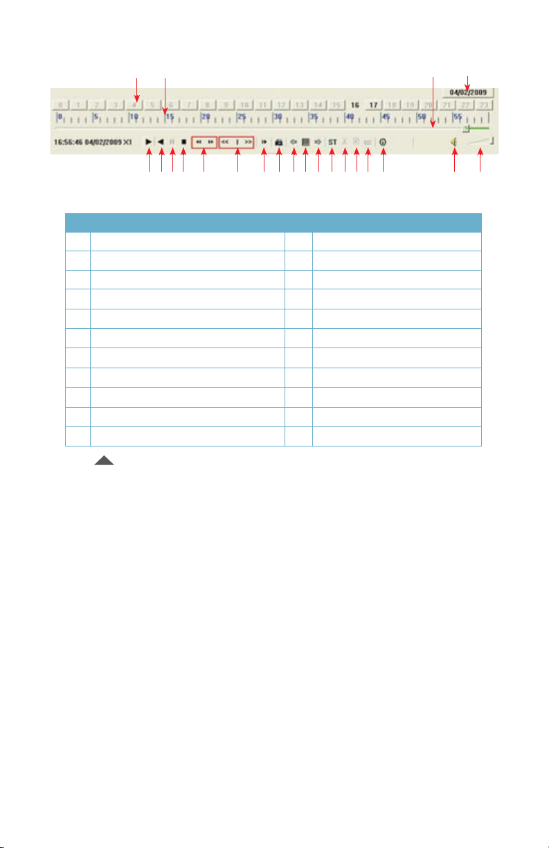
STEP 5. When you select Play, a Playback Control Bar will appear.
5 6 7 8 9 10 11 12 13 14 15 16 17 18 19 20 21 22
PICTURE 4-21
# Function # Function
1 Hour Blocks 2 Minute
3 Progress Bar 4 Date
5 Play 6 Previous Recording File
7 Pause 8 Stop
9 Previous Frame / Next Frame 10 Slow Play, Normal Play, Fast Play
11 Next Hour 12 Snapshot
13 Reduce window 14 Play All Channels
15 Add window 16 Start
17 Cut 18 Delete
19 Convert AVI 20 On-Screen Display
21 Mute 22 Volume
41 2 3
Click the button on the bottom of the multimedia player and then click the Play button
(Item number 5 in Picture 4-21) to start playing the file.
The Playback Control Bar shows the date the file was recorded. The Hour Blocks indicate
(in 24 hour format) at what hour the event took place. The green area in the Progress Bar
shows when in that hour the event occurred as well as how far the player is in the video
recording.
The example displayed in Picture 4-21 above, shows that the event being played was
recorded on April 2, 2009 from 4:57pm (16:57) to 5pm. Clicking on the Next Hour button
(Item number 11 in Picture 4-21) would take the user to the rest of the event beginning
at 5:00.00.
32
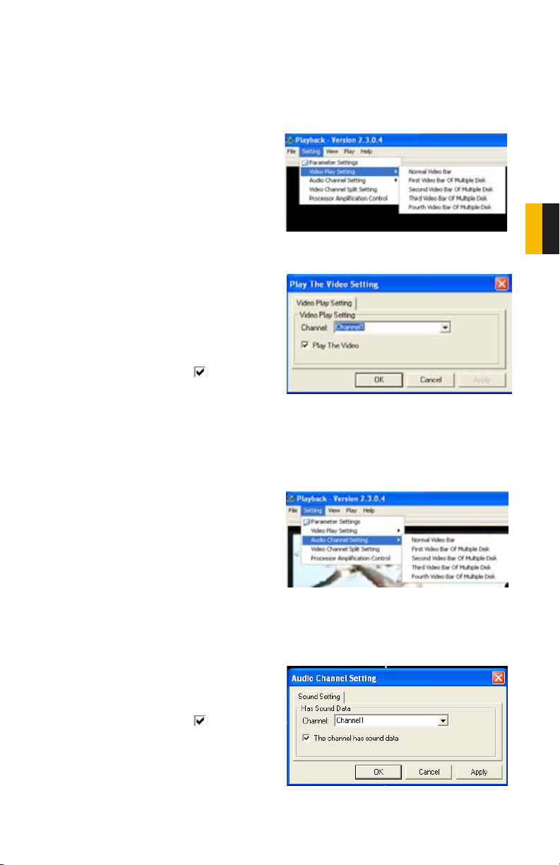
Video Play Settings
Each video record contains data from all the cameras that were recording at that time. You can
view up to four of those recordings at one time by clicking on the “Play All Channels” button
(Item number 14 in Picture 4-21). Or, you can choose which channel will be played back
in the Playback software by following these steps:
STEP 1. In the Setting menu in the
Playback software toolbar, select
Video Play Setting
CHAPTER 4 BASIC OPERATION
STEP 2. From that pull-down menu,
choose Normal Video Bar.
STEP 3. In the resulting pop-up window,
choose which channel you wish to
view.
STEP 4. Check the box next to “Play
the Video”. Click Apply then OK.
Audio Settings
If you have connected an audio-capable camera or a microphone to Channels 1 or 2, you can
play back recorded audio along with the video.
STEP 1. In the Setting menu in the
Playback software toolbar, select
Audio Channel Setting.
STEP 2. From that pull-down menu,
choose Normal Video Bar.
PICTURE 4-22
PICTURE 4-23
PICTURE 4-24
STEP 3. In the resulting pop-up window,
choose which channel you wish to
enable audio for.
STEP 4. Check the box
channel has sound data”. Click Apply
then OK.
next to “The
PICTURE 4-25
33
RECORDING
The controls for scheduling recording are mostly found in the Record menu which is
located in the Main Menu. Certain features, such as Motion Detection, are located
in the Advanced menu (also reachable through the Main Menu) but are included
here for ease of instruction.
CHAPTER 5
5.1 RECORDING CONFIGURATION
In addition to scheduling the recording times for your cameras, you can also set resolution
format, bitrate, recording block size, audio feed and recording mode among other parameters.
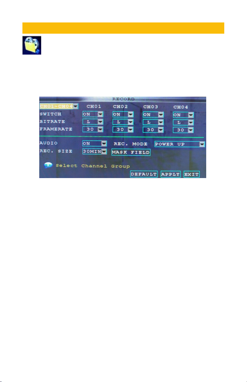
PICTURE 5-1
The menu will only display four channels at a time. The pull-down menu in the upper left of the
menu allows you to switch between groups of four channels; 1-4, 5-8, 9-12 and 13-16.
The recording options for each camera can be selected independently and are available below
each camera’s channel number.
CHANNEL. Enable/disable recording for a specific camera by toggling it On or Off using the
pull-down menu.
RESOLUTION On the QS 206, CIF is the only resolution option. The QS408 offers the larger
and clear D1 recording format on channels 1 and 2.
BITRATE Select BEST, FINE, or NORMAL. Set up the code rate for recording corresponding
to 768Kbps, 512Kbps and 384Kbps.
AUDIO If you have a powered microphone or audio-capable camera connected to Channels
1 and/or 2, you can select ENABLE to record the audio feeds. Audio feeds are not possible
on other channels.
REC. MODE Select POWER UP to record continuously from the time the DVR is turned on. If
you select TIMER RECORD, you will need to set a recording schedule on the system.
REC. SIZE Record Size sets the file size for recorded video files on the system. Instead of
recording data as one large file, the system will divide the data into blocks of 15, 30, 45, or 60
minutes. This makes the recorded data easier to search.
Click APPLY to save your settings. Click CLOSE in the confirmation window.
Click EXIT in every menu until all windows are closed.
34
5.2 RECORDING SCHEDULE
The DVR is set by default to record continuously on all channels. You can program the system
to record according to a customized recording schedule.
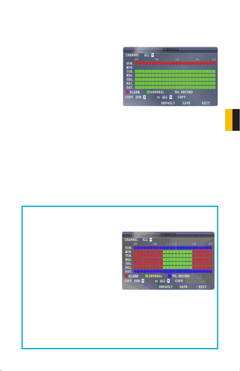
The Schedule Grid shows the days of the
week and hours 0~23. You can set Alarm
Recording (Red), General (Normal) Recording
(Green), or No Recording (Blue) to each time
block of each day.
To set a recording schedule:
STEP 1. Open the Main Menu and click RECORD.
STEP 2. Under REC. MODE, select TIMER RECORD.
STEP 3. Click SCHEDULE. The Schedule menu opens.
STEP 4. Under CHANNEL, select specific channels or select ALL.
STEP 5. Below the grid, click either ALARM (red), GENERAL (Green), or NO RECORD
(Blue) and then click a time block on the desired day.
STEP 6. Use the FROM/TO drop-down menus to copy the schedule of one day to
another. For example, if you want your schedule for Monday to be the same on
Wednesday: under FROM select MON, under TO select WED, and then click COPY.
STEP 7. Click SAVE.
STEP 8. Click EXIT in each menu until all windows are closed.
Example
You want your system to record continuously on all channels from 9 AM to 5 PM Monday
to Friday. You also want Alarm/Motion recording from 5 PM to 9 AM. You do not want the
system to record Saturday or Sunday.
STEP 1. Open the Schedule menu.
STEP 2. Under CHANNEL, select
ALL.
STEP 3. Click the blue NO RECORD
block below the grid. A checkmark
will appear in the block.
STEP 4. Under SUN, click blocks
00~23. The blocks will turn blue.
STEP 5. Under FROM, select SUN. Under TO select SAT, and then click COPY.
Step 6. Click the red ALARM block below the grid.
STEP 7. Under MON, click blocks 00~08 and blocks 18~23. The blocks will turn red.
STEP 8. Under FROM, select MON. Under TO select TUE, and then click COPY.
Repeat for Wednesday, Thursday, and Friday.
Your completed schedule should the same as the schedule in Picture 5-3. Save your
settings and Exit the window.
PICTURE 5-2
PICTURE 5-3
CHAPTER 5 RECORDING
35
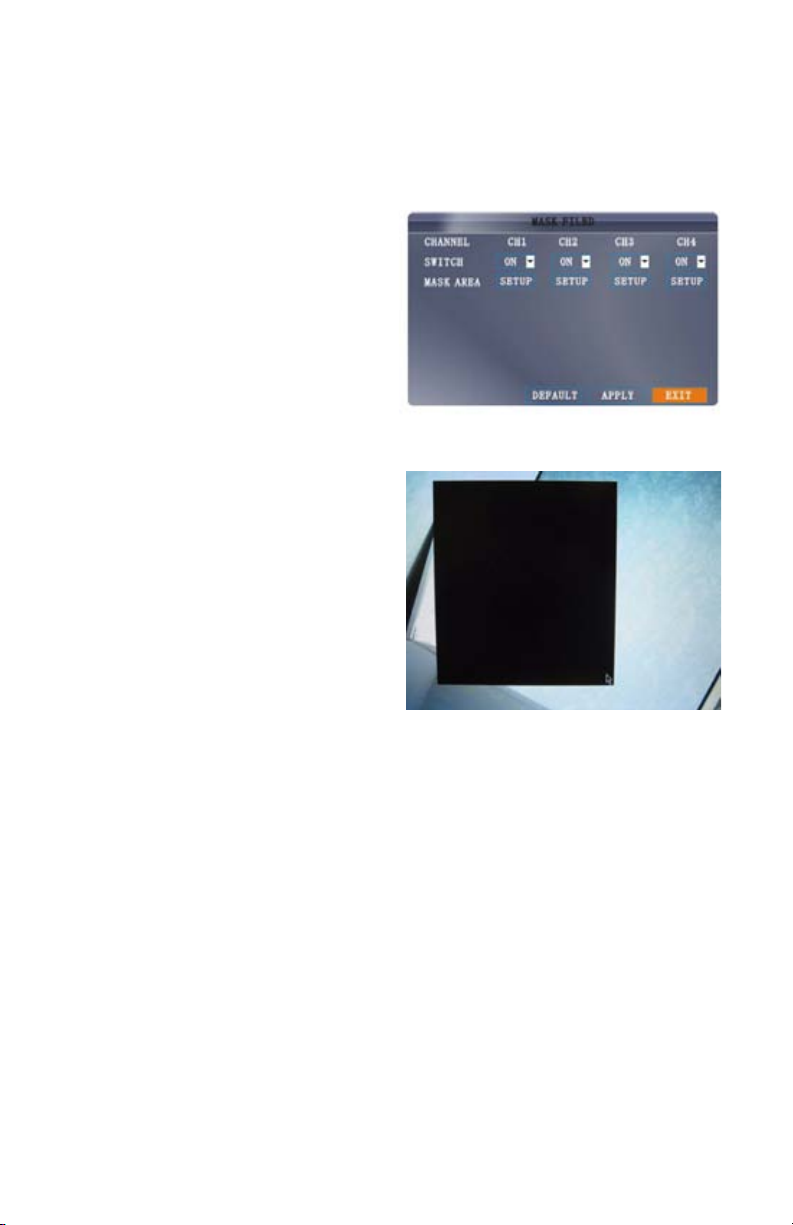
5.3 MASK FIELD
The Mask Field lets you block a specific portion of a channel you do not want recorded or
shown on the display screen. This can be useful if you need to conceal a sensitive area being
captured by the installed camera.
To use the mask field:
STEP 1. From the Record menu, click
MASK FIELD SETUP. The Mask
Field menu opens.
STEP 2. Choose a channel you wish to
apply the Mask Field.
STEP 3. Select ON from the SWITCH
drop-down menu.
STEP 4. Click SETUP. The Mask menu
will be replaced by the full-screen
camera view of the desired channel.
STEP 5. Using the mouse, click and drag
the cursor over the area you want to
conceal. A single click will produce a
small black square.
STEP 6. Right-click anywhere on the
screen to return to the Mask Field
menu.
STEP 7. Click APPLY. Click CLOSE in
the confirmation window.
STEP 8. Click EXIT in all menus until all
windows are closed.
PICTURE 5-4
PICTURE 5-5
36
5.4 MOTION DETECT
The Motion Detection menu can be found by accessing the Advance menu from the Main
Menu. In this menu you can configure motion detection for each channel.
The menu will only display four channels at a time. The pull-down menu in the upper left of the
menu allows you to switch between groups of four channels; 1-4, 5-8, 9-12 and 13-16.
The motion detection options for each camera can be selected independently and are
available below each camera’s channel number.
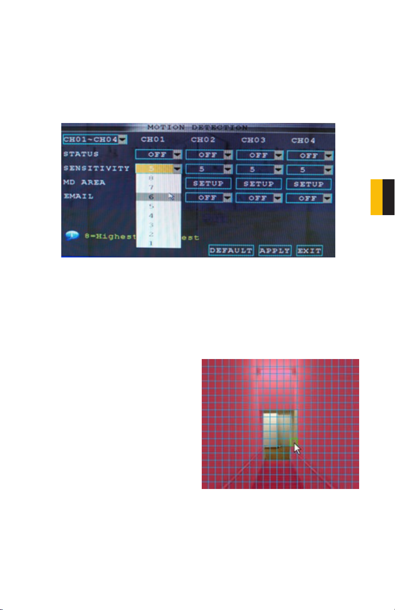
PICTURE 5-6
Motion Detection Settings
STATUS Select ON to enable motion detection for the desired channel.
SENSITIVITY Select 1 through 8. The higher the number, the more sensitive the motion
detection.
MD SETUP This allows you to chose which areas of the camera’s field of view should detect
motion.
STEP 1. Click SETUP and a motion
detection grid appears over the
selected camera’s video in full screen.
STEP 2. Click the blocks in the grid to
enable/disable motion detection.
Red=Motion detection enabled
Clear=Motion detection disabled.
STEP 3. Right-click anywhere on the
screen to return to the Motion
Detection menu.
STEP 4. Click APPLY. Click CLOSE in
the confirmation window.
STEP 5. Click EXIT in all menus until all
windows are closed.
PICTURE 5-7
CHAPTER 5 RECORDING
The Motion Detection buzzer can be enabled or disabled in the Alarm Setup menu covered in
Section 6.1 Alarms.
EMAIL An email alarm can be assigned to individual channels. Email notifications are covered
in Section 6.2 Email.
37
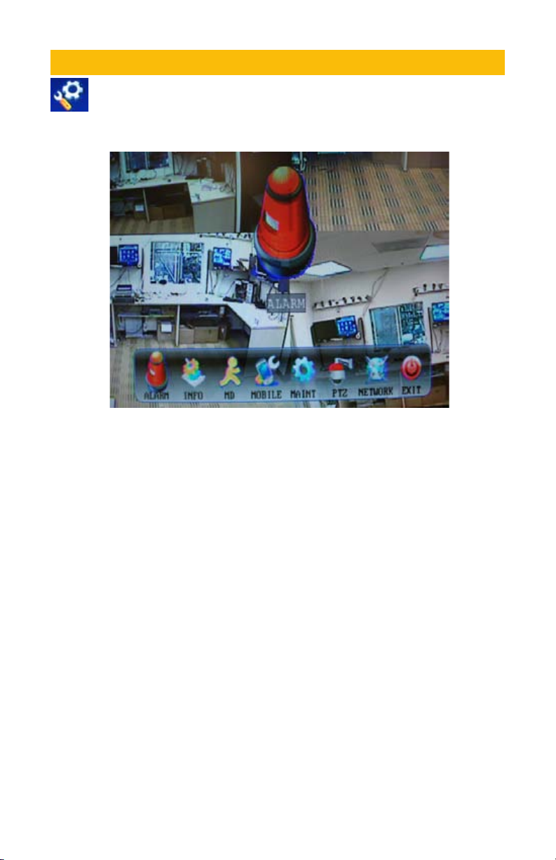
ADVANCED FEATURES
Use the Advanced Setup menu to configure alarm settings, motion detection,
mobile surveillance, PTZ settings and network settings. The Advanced Setup
menu contains the following sub-menus: Alarm, Info, Motion Detection, Mobile,
System, PTZ, and Network.
PICTURE 6-1
CHAPTER 6
38
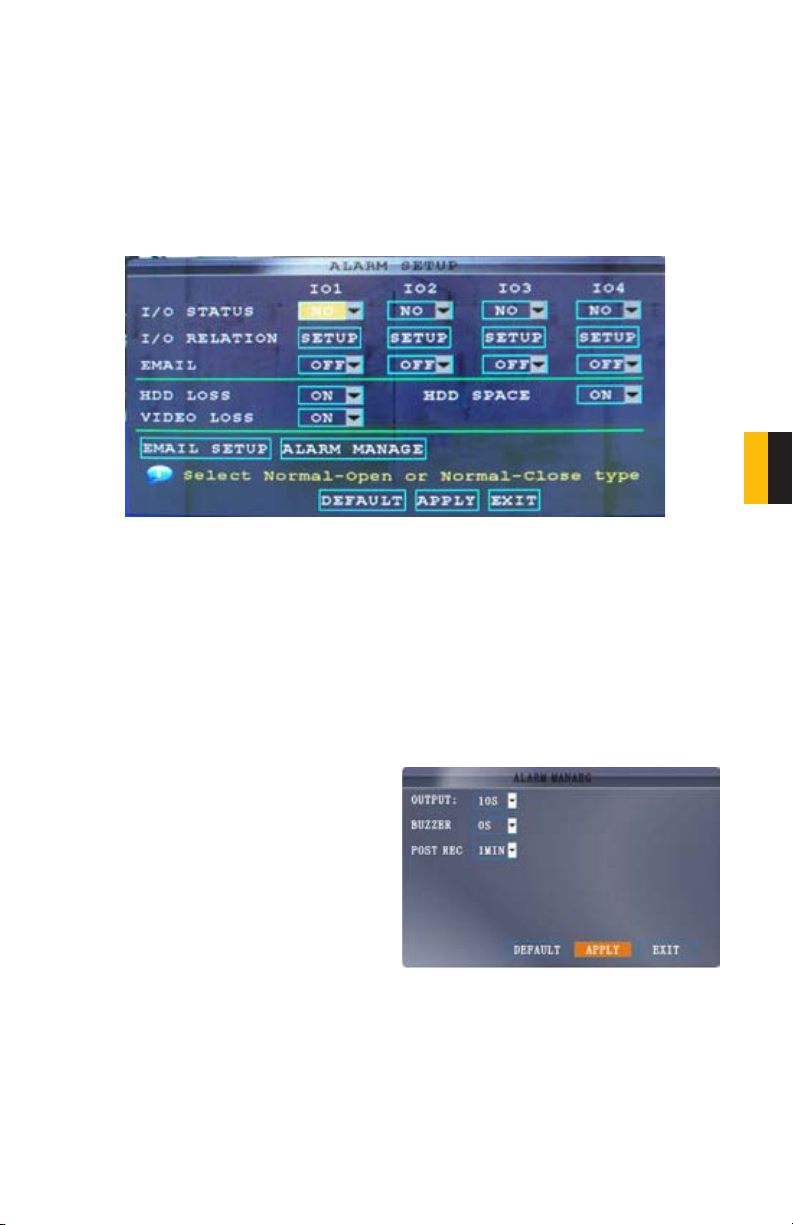
6.1 ALARM
Use the Alarm menu to configure alarm and email settings. External alarm devices must be
connected to the alarm block on the rear panel of the system in order to use the I/O (input/
Output) alarms of the system.
The motion detection options for each alarm channel can be selected independently and are
available below each port’s number.
PICTURE 6-2
ALARM SETTINGS
I/O CHANNEL Consult your alarm’s manual for the proper settings. Select NO (Normal Open),
NC (Normal Closed), or OFF.
HDD LOSS The alarm will sound if the internal hard drive is damaged
HDD SPACE The alarm will sound when the hard drive is full (if overwrite is disabled)
VIDEO LOSS The alarm will sound when a camera is disconnected
ALARM MANAGE Clicking on this button will open a new window.
OUTPUT Set the output time (in seconds)
on the spot monitor from 0, 10, 20, 40, or 60
seconds.
BUZZER Set the time (in seconds) for the
buzzer when an alarm is triggered—0, 10, 20,
40, or 60 seconds.
Set the buzzer to 0s if you want to disable the
alarm during motion detection
POST REC Set the time (in seconds) for the
system to record after a triggered alarm—0,
10, 20, 40, or 60 seconds.
PICTURE 6-3
CHAPTER 6 ADVANCED FEATURES
Click APPLY and then click CLOSE in the
confirmation window.
39
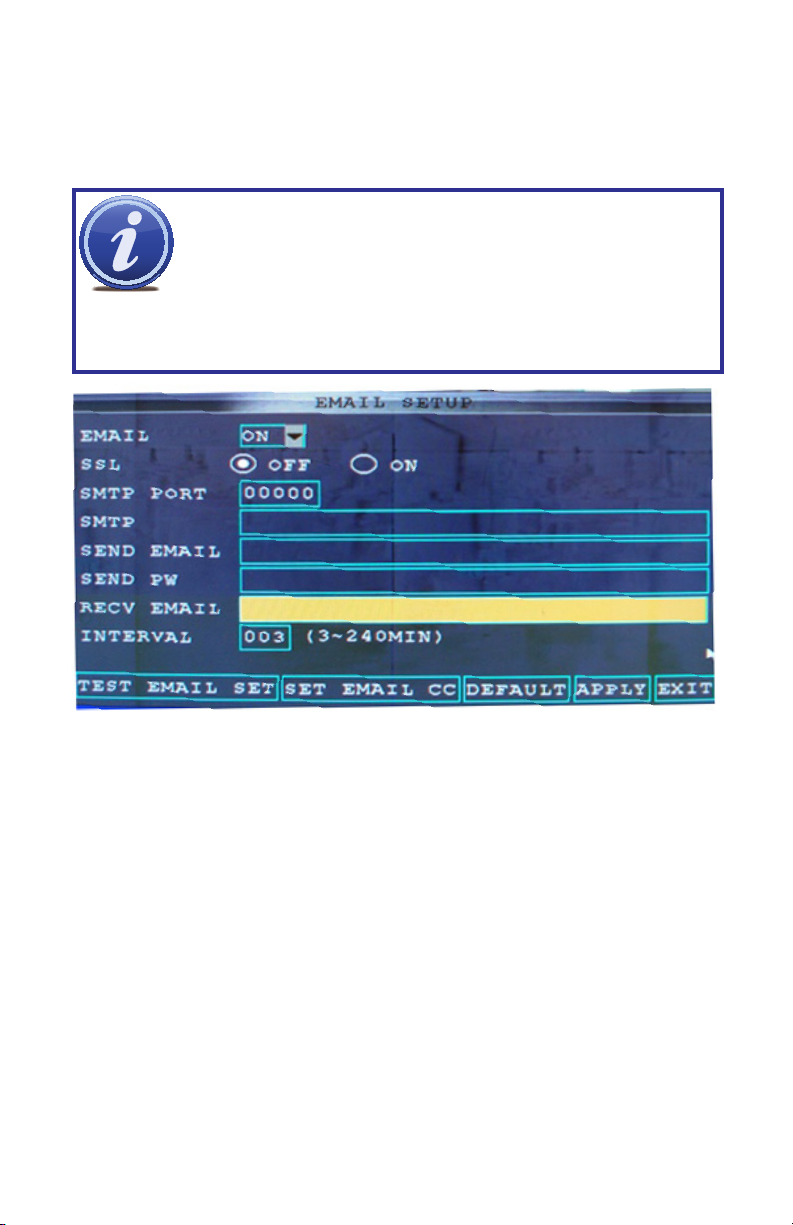
6.2 EMAIL SETUP
The system can send an email notification with a JPEG snapshot for triggered events on the
system. Selecting Email Setup in the Alarm Setup menu will open the Email Setup menu.
Your DVR will need to be connected to the Internet - either through a router or by being
directly connected to a modem - in order to be able to send out email alerts.
NOTE! Depending upon your settings, the system can generate a lot of e-mail
alerts. For that reason, we recommend setting up a dedicated e-mail address
specifically for the system to send alert notices. If you do not have your own
e-mail system (such as a corporate mail server) you should consider using a
limited amount of e-mail traffic we specifically recommend using Google’s Gmail service with
its higher limit. Similarly, you will want the alert e-mails to go to a different account than the
one sending them. This will ease your management of these alerts.
free e-mail provider. However, because many free e-mail services allow only a
PICTURE 6-4
For the example below, we will use Gmail. The settings can be found under Options when
logged into your Gmail account. If you have a corporate mail server, you will need to consult
with your IT department regarding proper settings.
STEP 1. Select ON in the pull-down menu to the right of EMAIL.
STEP 2. SSL Leave SSL turned OFF. SSL deals with encryption. Only advanced users
should enable this option.
STEP 3. SMTP PORT Enter the SMTP port of your email server. Gmail’s is 465.
STEP 4. SMTP Enter the SMTP address of your email server. For example, smtp.gmail.
com
STEP 5. SEND EMAIL The “from” address of your alerts.
STEP 6. SEND PW Enter the password of your sending email account
STEP 7. RECV EMAIL Enter the destination email address for your notifications.
STEP 8. Click APPLY and then click CLOSE in the confirmation window.
STEP 9. Click EXIT in all menus until all windows are closed.
40
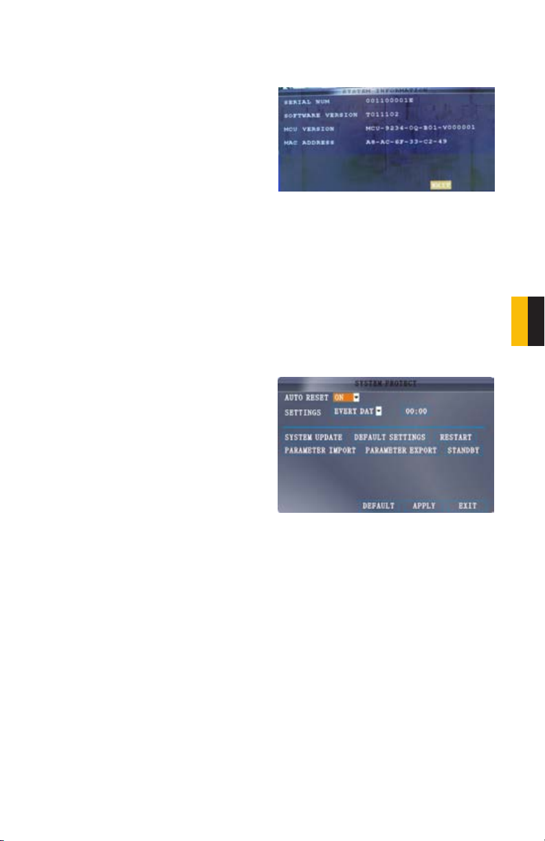
6.3 SYSTEM INFO
This window will allow you to view system information - including the firmware version, MAC
address, and serial number of the system.
Check this window to determine whether
you need to update to a newer version of the
firmware. Updating the firmware is covered in
Section 6.4 System.
PICTURE 6-5
MOTION DETECTION
This was covered in Section 5.4 Motion Detection.
MOBILE ACCESS
This will be covered in Section 7.4 Mobile Access
6.4 SYSTEM
Use the System menu to update system firmware and set an automatic system reset
schedule.
Like most conventional computers, the DVR
can benefit from being occasionally shut
down and re-started. This clears the memory
and improves performance.
ENABLING AUTO-RESET
STEP 1. Select On in the AUTO RESET
pull-down menu. The Settings option
will appear below.
STEP 2. In the SETTINGS pull-down
menu, select EVERY DAY, EVERY
WEEK, or EVERY MONTH. If you
choose EVERY MONTH, the date
drop-down menu will appear.
STEP 3. Select the date for auto-reset
from the drop-down menu.
STEP 4. Enter the time for auto-reset
using the Virtual Keyboard.
STEP 5. Click APPLY, then click CLOSE
in the confirmation window.
PICTURE 6-6
CHAPTER 6 ADVANCED FEATURES
41

RESTORING FACTORY SETTINGS
STEP 1. Click DEFAULT SETTINGS. This will restore the system to the original factory
settings.
STEP 2. Click OK in the prompt.
IMPORTANT! Restoring factory settings will cause any settings you’ve made
to the system to be removed! This includes recording and network setups
along with passwords!
RESTARTING THE DVR (SOFT-RESET)
STEP 1. Click RESTART.
STEP 2. Click OK in the prompt. The system will perform a soft-reset and load to a live
split-screen view.
UPGRADING THE FIRMWARE
STEP 1. Copy the firmware file to an
empty USB flash drive. The firmware
file should not be in a folder.
STEP 2. Connect the USB flash drive to
the top USB port on the front panel of
your system.
STEP 3. Open the System Menu.
STEP 4. Click FIRMWARE UPDATE.
The system will scan the USB
flash drive and begin updating the
firmware. Do not remove the USB
flash drive while the upgrade is
taking place.
STEP 5. Click CLOSE in the confirmation
window. In the system prompt, click
OK. The system will restart.
PICTURE 6-7
42

6.5 PAN-TILT-ZOOM CAMERAS (PTZ)
Use the PTZ Setup menu to configure settings for an optional PTZ camera.
NOTE! Consult the instruction manual of your PTZ camera for complete
information about your camera, including protocol and baud rate.
The menu will only display four channels at a time. The pull-down menu in the upper left of the
menu allows you to switch between groups of four channels; 1-4, 5-8, 9-12 and 13-16.
The PTZ setting options for each camera can be selected independently and are available
below each camera’s channel number.
CHAPTER 6 ADVANCED FEATURES
PICTURE 6-8
Configuring a PTZ camera:
STEP 1. Connect a PTZ camera to the BNC and 485A (TX, +) and 485B (RX, -) ports and
power outlet.
STEP 2. PROTOCOL Select PELCO-D or PELCO-P for the selected channel.
STEP 3. BAUD RATE Select 1200, 2400, 4800, or 9600.
STEP 4. DATA BIT Select 5, 6, 7, or 8.
STEP 5. STOP BIT Select 1 or 2.
STEP 6. VERIFY Select ODD, EVEN, MARK, SPACE, or NONE.
STEP 7. ADDRESS Enter an address from 001~255 using the Virtual Keyboard. Refer to
your PTZ camera`s instruction manual for further details.
STEP 8. Click APPLY and then click CLOSE in the confirmation window.
STEP 9. Click EXIT in all menus until all windows are closed.
43

REMOTE ACCESS
CHAPTER 7
If you are only going to access the DVR from a computer that is attached to the same router
as the DVR you only need to setup the information in the NETWORK settings using either
the DHCP option or assigning a static IP following the instructions below. Since you are just
going from one location to another on the same network, port forwarding and knowing the
public IP address are not necessary. You will just access the DVR by entering the IP address
of the DVR from the NETWORK setup into the Internet Explorer browser window. After you
setup the NETWORK settings using DHCP or Static IP instructions skip down to the section
Accessing the DVR through Internet Explorer.
The Network Settings menu is reached from the Advanced Settings menu - which is
found in the Main Menu.
PICTURE 7-1
7.1 NETWORK SETUP
There are five ways you can setup the DVR to be accessed remotely; DHCP, UPnP, Static IP,
PPPOE, and DDNS. The Network Setup menu is accessed through the Main Menu.
DHCP
Select DHCP from the drop down box and
then select the Apply button so the router
can find it and assign it an IP address. After
the router has assigned the DVR an IP
address it is a good idea to write down this
address and then select Static from the drop
down box and enter this address as a static
address so it will not change if you shutdown
DVR or the router. This is the IP address you
will forward port 80 to on the router so you
can access the DVR from remote computers.
44
NETWORK SETUP
TY PE
ME DI A P OR T
WE B POR T
DN S
DD NS SE TT ING S UP NP O PE N CLO SE
DH CP
09 00 0
00 08 0
2 02 . 09 6 .1 3 4. 1 33
DEFAULT
APPLY EXIT
PICTURE 7-2

UPNP
Shut Down
Universal Plug and Play, or UPnP for short, is a new set of networking protocols created by
consumer electronics manufacturers to allow easier connections of networked devices such
as computers, printers, mobile devices and network-capable security DVRs. Your DVR has
UPnP functionality built in which allows it to automatically seamlessly connect to a network,
obtain an IP address on that network and interact with other devices on the network - without
the need for special software or time-consuming configuration routines.
Your Router must support UPNP function in order to use this protocol.
NOTE! The DVR and PC must be connected to the same router.
Things you will need to know :
1. The make and model of the router.
2. Whether your router supports UPnP
3. The IP address for the router.
4. You will be forwarding ports 80, 100 and 9000.
NOTE! Check with your DVR’s owner manual or the website of your router’s
manufacturer to determine whether it supports UPnP. If it does not, then you
will need to follow the instructions for Simple Port Forwarding as laid out
in Section 7.2. If you are still unsure about whether your router supports UPnP, you can
determine this by proceeding with Part 1, below.
CHAPTER 7 REMOTE ACCESS
PART 1: ACCESSING YOUR ROUTER
You will need your router’s IP address in order to access it’s controls.
To locate the IP address of your router:
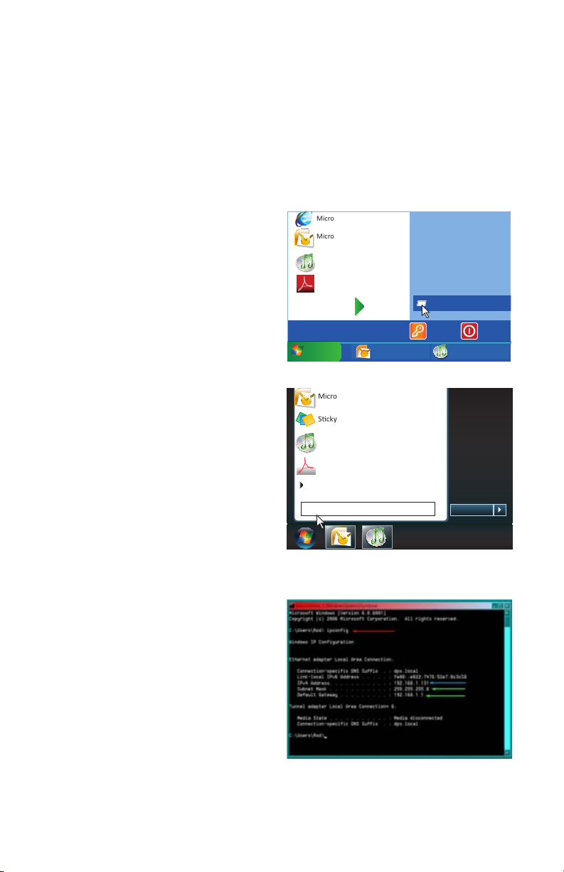
STEP 1. To access the router’s settings you will need to enter the Command (CMD)
panel on a computer also connected to the same router.
A. WINDOWS XP – Select Run from
your Windows START menu (lower
left of screen) and type “cmd” after
the prompt.
Microso Internet Explorer
Microso Office Outlook 2007
iTunes
Adobe Acrobat
All Programs
start
start
Inbox Microsof... iTunes
Devices and Printers
Default Programs
Help and Support
Run
Log Off
PICTURE 7-3
45

B. WINDOWS VISTA and WINDOWS
Devices and Printers
Default Programs
Help and Support
7 – Click on the START menu
(Windows icon) in the lower left of
your screen. Type “cmd” into the field
that says, “Search programs and
files” and hit ENTER or click on the
magnifying glass icon.
STEP 2. Type “ipconfig” at the prompt
(Red arrow in Picture 3) to access
router settings.
STEP 3. The “Default Gateway” (Yellow
arrow) is the IP address for your
router.
PART 2: ACTIVATING UPnP in the router
Microso Office Outlook 2007
Scky Notes
iTunes
Adobe Acrobat
All Programs
cmd
PICTURE 7-4
PICTURE 7-5
Shut down
STEP 4. Enter the router’s IP address into the address field in a web browser window.
This will open your router’s settings window.
STEP 5. Activate UPnP. Each manufacturer uses their own method for locating and
activating UPnP as shown by the red boxes in the example pictures below. Again, you
should consult your router’s manual or the manufacturer’s website for specifics.
PICTURE 7-6
PICTURE 7-7
46

PART 3: ACTIVATING UPnP in the
DVR
STEP 6. On the DVR, access the
Network menu from the Advanced
Settings menu.
PICTURE 7-8
CHAPTER 7 REMOTE ACCESS
STEP 7. Set Network Type to DHCP
and click OPEN next to UPNP.
STEP 8. Click on Apply and then OK
to save your settings before exiting
TY PE
ME DI A P OR T
WE B POR T
PICTURE 7-9
NETWORK SETUP
DH CP
09 00 0
00 08 0
this menu.
STEP 9. Restart your DVR.
DN S
DD NS SE TT ING S UP NP O PE N CLO SE
2 02 . 09 6 .1 3 4. 1 33
DEFAULT
APPLY EXIT
PICTURE 7-10
STEP 10. Check the status of ports 80,
100 and 9000, by going to www.
canyouseeme.org and entering the
port numbers one at a time.
If you receive the “Success!”
message then you are ready to begin
remotely monitoring your DVR by
PICTURE 7-11
entering the IP address displayed by
CanYouSeeMe.
If you do not receive the “Success!” message, you should change the port number listed to
the right of Web Port (see Picture 7-10) from 80 to 85 or 89 in the Network Settings Menu
and begin again with Step 8.
47
STATIC IP
Shut Down
Devices and Printers
Default Programs
Help and Support
You will need to setup the network settings on the DVR to match the settings of the router to
which your DVR is connected. Owners of 2Wire Brand routers should use DHCP.
To get the router settings:
STEP 1. To access the router’s settings you will need to enter the Command (CMD)
panel on a computer also connected to the same router.
A. WINDOWS XP – Select Run from
your Windows START menu (lower
left of screen) and type “cmd” after
the prompt.
B. WINDOWS VISTA and WINDOWS
7 – Click on the START menu
(Windows icon) in the lower left of
your screen. Type “cmd” into the field
that says, “Search programs and
files” and hit ENTER or click on the
magnifying glass icon.
STEP 2. Type “ipconfig” at the prompt
(Red arrow in Picture 7-14) to
access router settings.
Microso Internet Explorer
Microso Office Outlook 2007
iTunes
Adobe Acrobat
All Programs
start
start
Inbox Microsof... iTunes
PICTURE 7-12
Microso Office Outlook 2007
Scky Notes
iTunes
Adobe Acrobat
All Programs
cmd
PICTURE 7-13
Devices and Printers
Default Programs
Help and Support
Run
Log Off
Shut down
STEP 3. Write down the IP4v address
(Blue arrow) as well as the gateway
and subnet mask numbers (Green
arrows).
48
PICTURE 7-14

STEP 4. so you can copy them into the
Network Settings menu on the DVR
(Green arrows in Picture 7-15).
STEP 5. To create the DVRs IP address
(Red arrow in Picture 7-15) you
will need to enter the same first 3
sets of numbers as the gateway and
select a fourth set of numbers that
is different then any other device
attached to the same router. If the
IP address of your computer in the
ipconfig (Blue arrow in Picture
7-14) is a single or two-digit number
you should be ok with any three digit
number, if the computer IP address
ends with a number in the 100s then
you should go with a 200 number.
PICTURE 7-15
PPPOE
If you are going to attach the DVR directly to a DSL or Cable modem instead of a router you
will want to select the PPPOE option in the NETWORK options.
Contact your ISP for the User Name and
Password needed for the router. Select
PPOE from the Type pull-down menu and hit
OK. Enter the User Name and Password into
the appropriate fields.
PICTURE 7-16
CHAPTER 7 REMOTE ACCESS
49
7.2 PORT FORWARDING
Port Forwarding allows computers and devices outside of your network to communicate with
the DVR. You will need to forward ports 80, 100 and 9000 from the attached router to the IP
address of the DVR.
NOTE! The DVR and PC must be connected to the same router and both
must be powered up before proceeding.
Things you will need to know :
1. The make and model of the router.
2. If you changed the default router login, then you will need to know the user name and
password for that router.
3. The IP address for the router.
4. You will be forwarding ports 80, 9000 and 100.
PART 1: DETERMINE THE IP ADDRESS OF THE DVR
To find out the IP of DVR for QS series DVR do the following:
M A I N M E N U
Using the mouse, right-click and then select
Main Menu in the pop-up shortcut menu.
M U L T I P I C T U R E
P T Z
V I D E O S E A R C H
M U T E
PICTURE 7-17
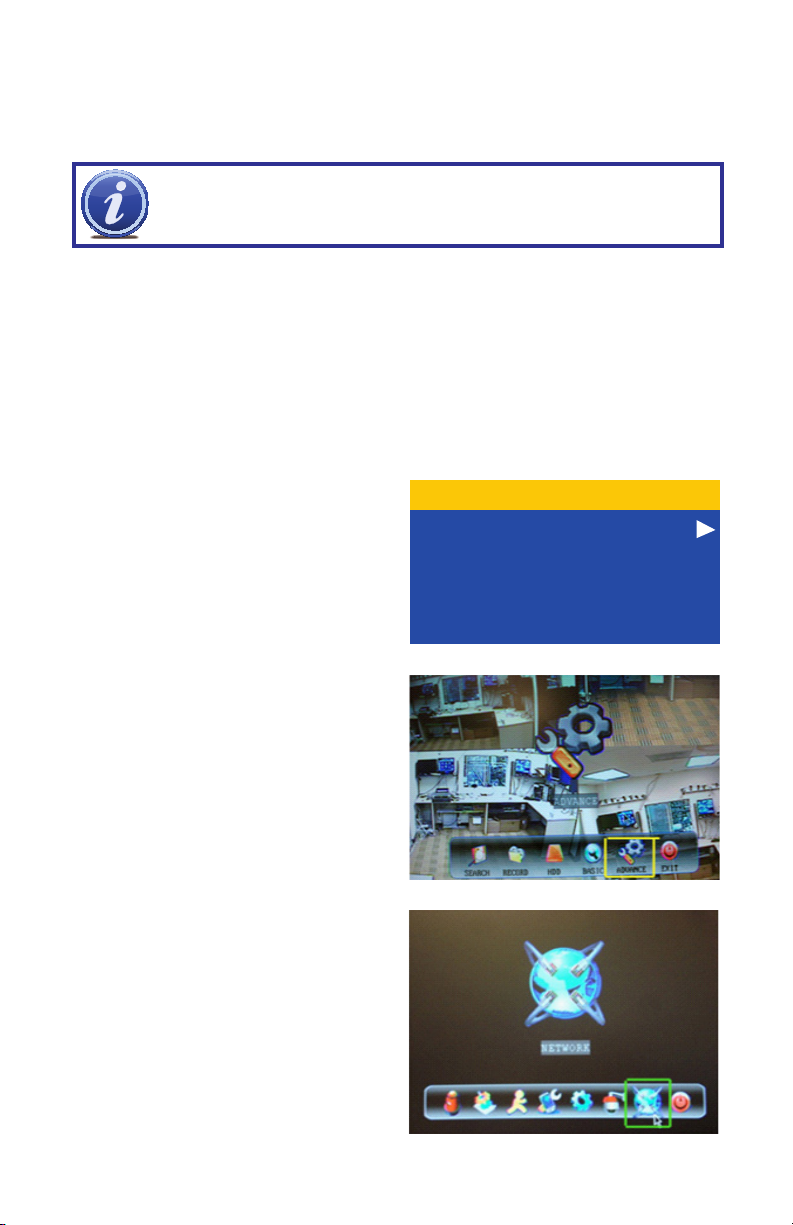
Select ADVANCE in the Main Menu
window.
Click on NETWORK in the Advanced
Settings Menu.
50
PICTURE 7-18
PICTURE 7-19

STEP 1. Select DHCP from the Type
drop-down menu,
STEP 2. Click on APPLY
STEP 3. Select EXIT.
STEP 4. Restart the DVR.
PICTURE 7-20
Once the DVR has restarted, reopen the
Network Setup window and the IP address
of the DVR will now be listed. This is the
address to which you will forward ports 80
and 9000. If you plan to access your DVR via
a smartphone, you will need to forward port
100 as well.
PICTURE 7-21
PART 2: DETERMINE THE NUMBER OF ROUTERS ON THE NETWORK
To find out the number of routers on your network, you will need to download a FREE router
detection program.
STEP 1. Go to http://www.pcwintech.
com/shanes-toolbox
CHAPTER 7 REMOTE ACCESS
STEP 2. Click on Detect Multiple
Routers to begin the download.
STEP 3. Unzip the application to install it.
STEP 4. Click on the detect_routers
application to run it.
PICTURE 7-22
PICTURE 7-23
51
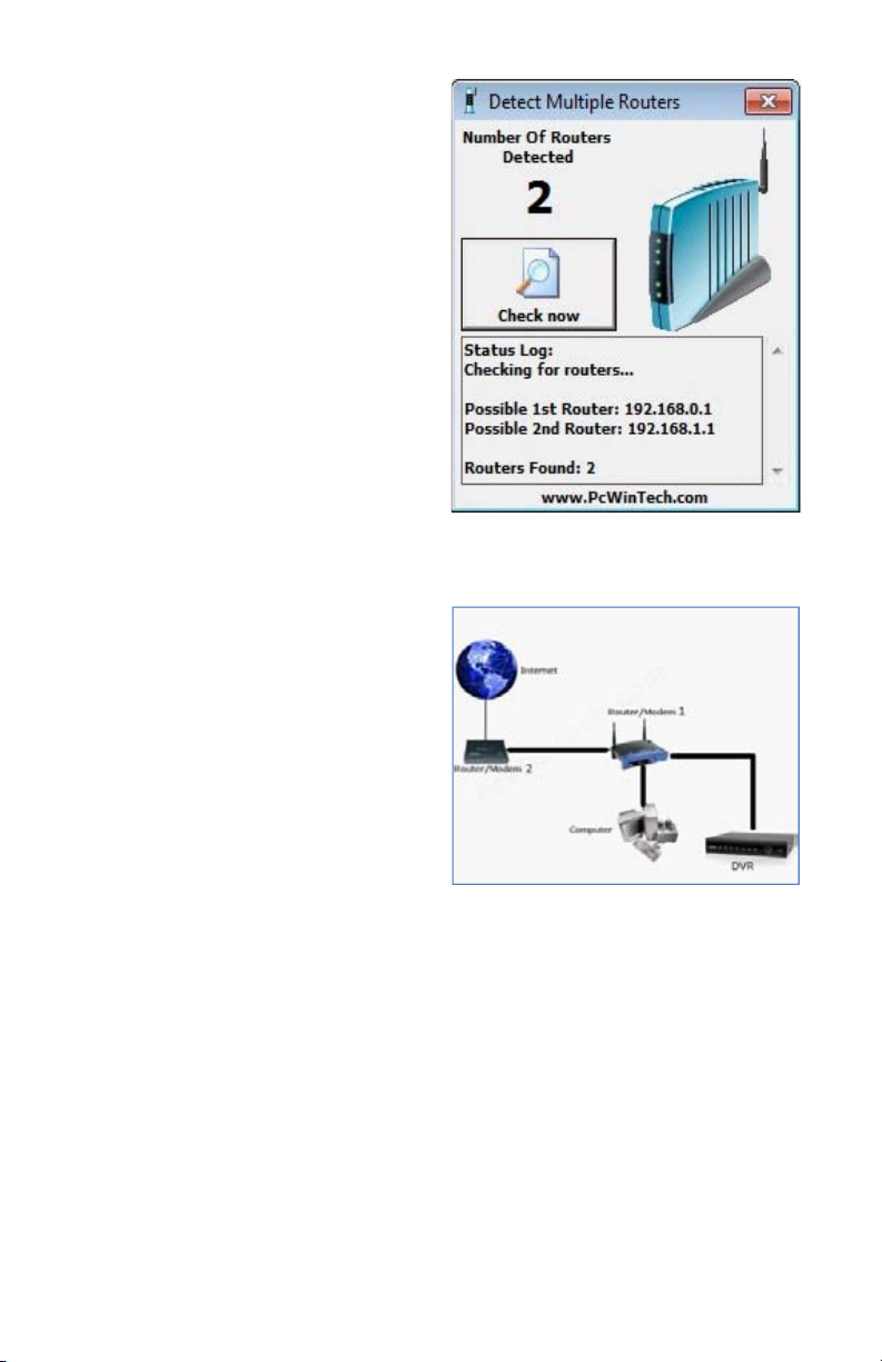
STEP 5. Click on CHECK NOW to
detect how many Routers are in the
network.
PICTURE 7-24
STEP 6. If there is only one router detected, then you may skip to Step 3: Simple Port
Forwarding.
If Multiple Routers are Detected
If there are multiple routers, you will see a
display similar to Picture 7-25.
If so, it may be preferable to connect your
DVR and computer to the router that
connects directly to the Internet. However,
this is not always possible depending upon
your particular situation.
PICTURE 7-25
In this case, you will need to proceed with the next section using the IP address for Router 1
to forward its ports. After that, you will need to proceed with Part 4: Setting Up DMZ on
Router 2.
52
PART 3: DOWNLOAD SIMPLE PORT FORWARDING PROGRAM
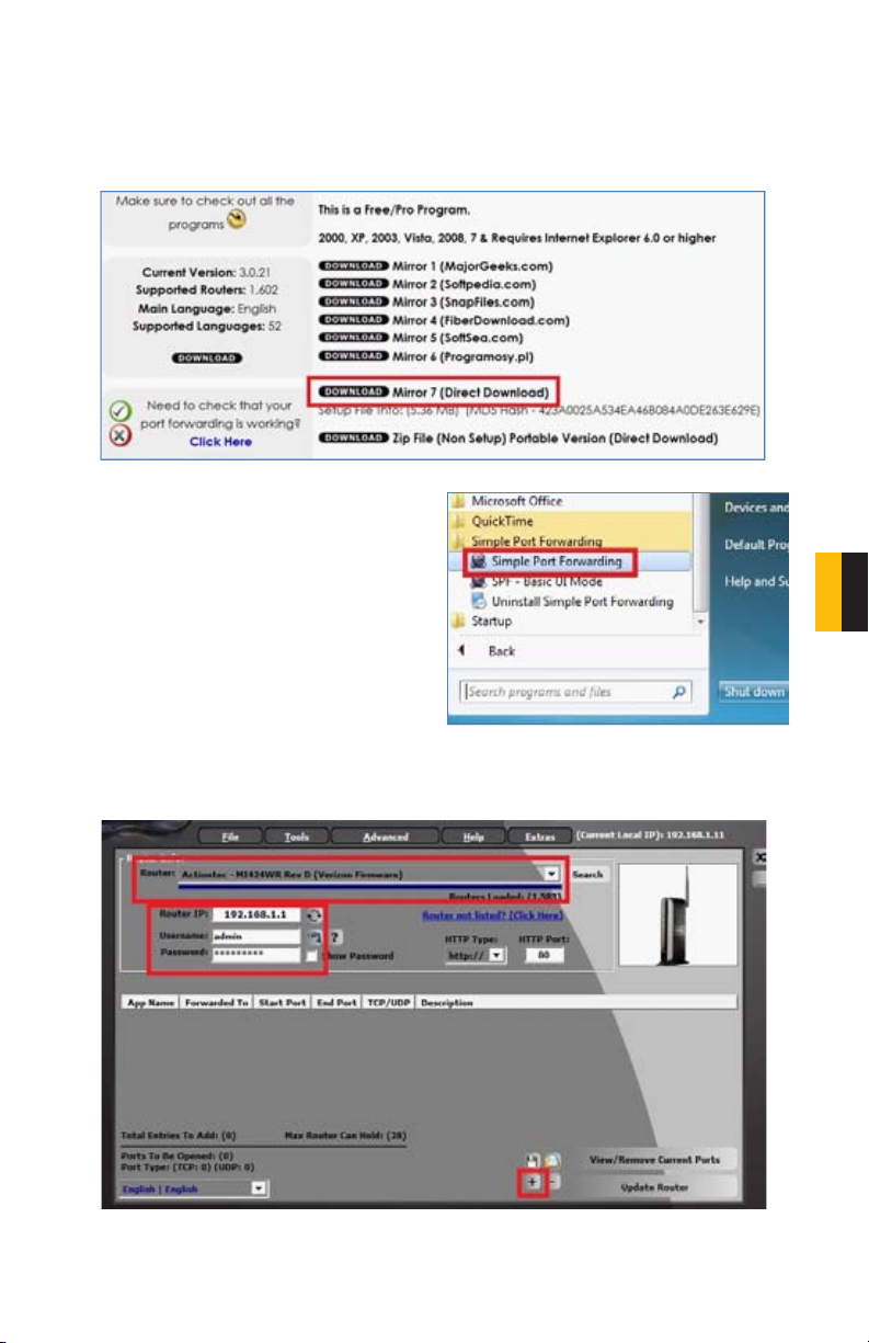
Download the FREE Simple Port Forwarding program from:
http://www.simpleportforwarding.com/download
Click on Download on Mirror 7 to download and install this program.
PICTURE 7-26
Once the program is installed, go to the Windows Start Menu (Windows icon in the lower
left of your monitor) and look for Simple Port
Forwarding in the program list. Click on the
program to launch it.
CHAPTER 7 REMOTE ACCESS
PICTURE 7-27
Once Simple Port Forwarding has launched, select your router from the list. The default
Router IP and Login information will automatically come up. If you have previously changed
the login information, then you will have to enter it manually
PICTURE 7-28
Click on “+” at the bottom to open the window allowing you to set your ports.
53
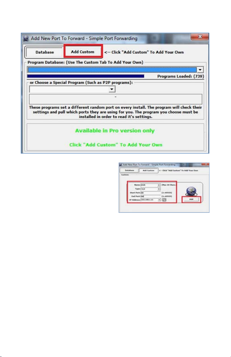
Click on ADD CUSTOM.
PICTURE 7-29
Input the required information:
Name: (You can name your DVR if you wish)
Type: TCP
Start Port: 80
End Port:80
IP add: IP of DVR obtained in Step 1.
Click on ADD
Repeat for port 9000, and also for 100 to allow smartphone access.
PICTURE 7-30
54
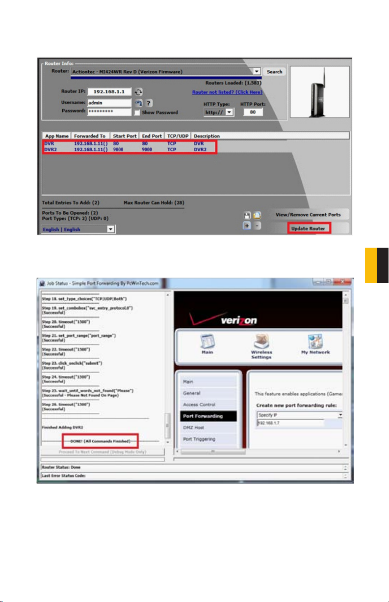
You will now be returned to the main window of the program. The ports you added will now
show on the list. Click on Update Router at the bottom.
PICTURE 7-31
You will see the “Updating is in progress” message. Please wait until you see it say DONE at
the bottom.
PICTURE 7-32
CHAPTER 7 REMOTE ACCESS
55
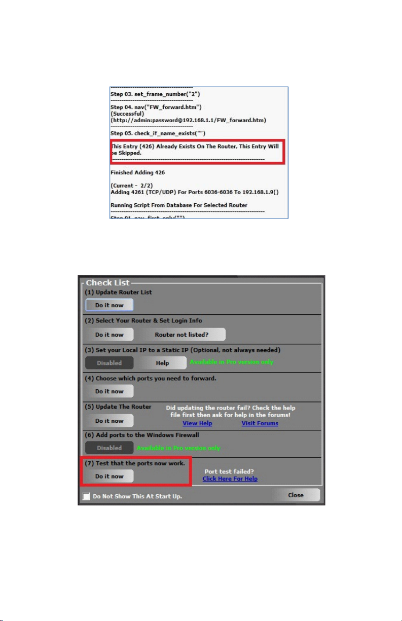
If for some reason, a port or ports that you forwarded are not listed in the Router and if you
see a message in the Scripts list on the left side of the window stating that the port already
exists (Red box in Picture 7-33), then you will need to change the Port 80 to 85 in the DVR
and start over again.
PICTURE 7-33
Once you receive the DONE message that the ports have been successfully forwarded, test
if the ports are working by clicking on item number 7 in the Check List - Test that the ports
now work.
56
PICTURE 7-34
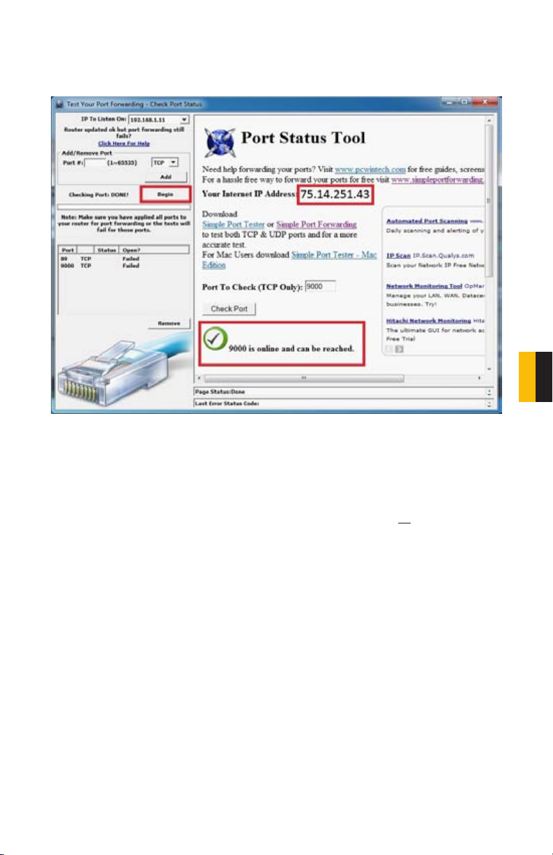
Click on Begin.
If you receive a message stating that the port is online and can be reached, then you have set
it up correctly.
PICTURE 7-35
To connect to your DVR from the Internet, you will need to put the Internet IP address shown
after “Your Internet Address:” message into the browser or access program window.
CHAPTER 7 REMOTE ACCESS
If you are forwarding any instead of port 80, then you need to put that port at the end of the
address.
Example: if you use port 85, you will need to enter: http://75.14.251.43:85
57

PART 4: SETTING UP DMZ IN ROUTER 2
NOTE! You will only need to proceed with this section if you detected a
second router in Part 2.
STEP 1. Login into Router 1 by putting
the IP of Router 1 into the Internet
Explorer browser, as in the example
shown in Picture 7-36 where the IP
address of Router 1 is 192.168.0.1
STEP 2. Find the status page on the
router settings that shows the WAN/
Internet IP address and write it down
this WAN IP address.
STEP 3. Log into the Router 2 by putting
the IP of Router 2 into the Internet
Explorer browser, as in example
shown in Picture 7-36 where the IP
address of Router 2 is 192.168.1.1
STEP 4. Find the DMZ page in the
router settings.
STEP 5. Enter the WAN IP for Router 1
into the DMZ page and enable DMZ.
NOTE! If you do not have a DMZ setting in the router, check to see if there
is a Bridge setting. If so, then use the Bridge setting instead of DMZ.
PICTURE 7-36
STEP 6. Save your changes.
You have forwarded the ports on the router to which the DVR is connected, to the IP address
of the DVR, and set the primary router to pass the connection to this router.
58

7.3 DDNS (DYNAMIC DOMAIN NAME SERVICE)
You can access the DVR over the Internet using a static or dynamic IP address. However, your
service provider can change this dynamic address from time to time. When it changes, you
will have to return to www.MyIPAaddress.com, again from a computer attached to the same
router as the DVR to get the new public IP address.
There are two solutions to this problem. The first would be to obtain a static IP address from
your ISP – which can be expensive. A second – and free – option is to use a dynamic domain
name service (DDNS) to get a domain name that can be linked to your dynamic IP address. In
addition to automatically keeping up with the changes in the address, you will now be able to
enter a domain name rather than a string of digits when accessing the DVR in Internet Explorer.
While there are multiple free DDNS services available, we recommend using www.MyQ-See.
com or www.DynDNS.com as the DVR has been already configured to accept account
information from these two services.
NOTE! Before setting up DDNS, you must have previously set up Port
Forwarding as described in the previous section.
Setting up DDNS
The following instructions are for setting up DDNS with MyQ-See, instructions for DynDNS are
available on their website.
STEP 1. Using a computer that is
connected to the same router as the
DVR, use Internet Explorer to go to
www.MyQ-See.com
STEP 2. Fill out the required information
to register and click the Submit
button at the bottom of the screen.
STEP 3. The next page will ask you
to create a domain name. Domain
names must begin with a letter (a-z)
or a number (0-9) and cannot contain
a hyphen. Once you’ve decided
upon a name, click on the “Request
Domain” button. If it is available you
will see a confirmation screen along
with the IP address associated with it.
Confirm that this matches the number
obtained in Network Settings. Your
domain name will look like this:
http://example.myq-see.com
STEP 4. Once you have obtained your
domain name, you will need to
configure the DVR for access using it.
PICTURE 7-37
PICTURE 7-38
59
CHAPTER 7 REMOTE ACCESS

To set up the DVR for access through a dynamic domain name:
STEP 1. Return to the Network window in the DVR.
STEP 2. Click on DDN Settings (Purple
box in Picture 7-39) and then click
on the APPLY option. This will open
the DDNS Setup window.
STEP 3. In the DDNS Setup Window,
Select the service – MyQ-See or
DynDNS you are using and enter the
account information you registered
with the domain name service.
DDNS: Select the ON option from the drop
down menu.
Service: Select myq-see from the drop down
menu.
Host Name: Enter the account name you setup on the myq-see site.
Username: Enter the email address you used on the myq-see site.
Password: Enter the password you setup on the myq-see site.
PICTURE 7-39
PICTURE 7-40
60

7.4 ACCESSING YOUR DVR REMOTELY
Once you have configured the network settings on the DVR to match those on your router
and forwarded the ports needed by the DVR to enable remote access over the Internet, you
will be ready to remotely view your cameras using a webcam program based on an ActiveX
control. For this to work, you will have to enable the ActiveX control options that are built into
Internet Explorer. It is strongly suggested that you be running the latest version of Internet
Explorer (currently IE8). The instructions below will describe the process using that version of
the browser. Instructions for users with IE6 or 7 are available in the Resources library of our
Technical Support page.
ACCESSING THE DVR USING INTERNET EXPLORER
User Account Control for Windows Vista and Windows 7
Some users of computers using Windows Vista or Windows 7 operating systems may receive
an error message informing of a codec that is missing or not installed. This conflict can be
resolved by turning off User Account Control (UAC).
Windows Vista
STEP 1. Open the Control Panel
(accessible by clicking on the
Windows icon in the lower left of your
screen.
PICTURE 7-41
CHAPTER 7 REMOTE ACCESS
STEP 2. Select User Accounts and
Family Safety.
STEP 3. Select “Add or Remove User
Account.”
STEP 4. Select the desired user account.
PICTURE 7-42
PICTURE 7-43
PICTURE 7-44
61

STEP 5. Select Turn User Account
Control on or off
STEP 6. Uncheck the box next to “Use
User Account Control (UAC) to help
protect your computer.”
STEP 7. You will then be asked to restart
your computer for the change to take
effect.
PICTURE 7-45
PICTURE 7-46
Windows 7
STEP 1. Open up the Start Menu
(accessible by clicking on the
Windows icon in the lower left of your
screen.
STEP 2. Type “uac” into the search bar
and hit ENTER. The User Account
Control will open or you will be offered
a link to click to open it.
STEP 3. Move slider to lowest setting
and press OK.
62
Microso Office Outlook 2007
Scky Notes
iTunes
Adobe Acrobat
All Programs
uac
PICTURE 7-47
PICTURE 7-48
Devices and Printers
Default Programs
Help and Support
Shut down

Setting Up ActiveX Control
STEP 1. Open Internet Explorer
STEP 2. Click on Tools
STEP 3. Select Internet Options in the
pull-down menu
STEP 4. Click on the Security Tab
STEP 5. Select Trusted Sites
STEP 6. Click on the Sites button
STEP 7. Uncheck the “Require server
verification (https:) for all sites in
this zone” button.
STEP 8. Type the DVR’s IP address
(obtained during Network Setup)
or DDNS domain name into the “Add
this website to the zone:” box.
STEP 9. Click the Add button
STEP 10. Close the window.
PICTURE 7-49
CHAPTER 7 REMOTE ACCESS
PICTURE 7-50
PICTURE 7-51
63
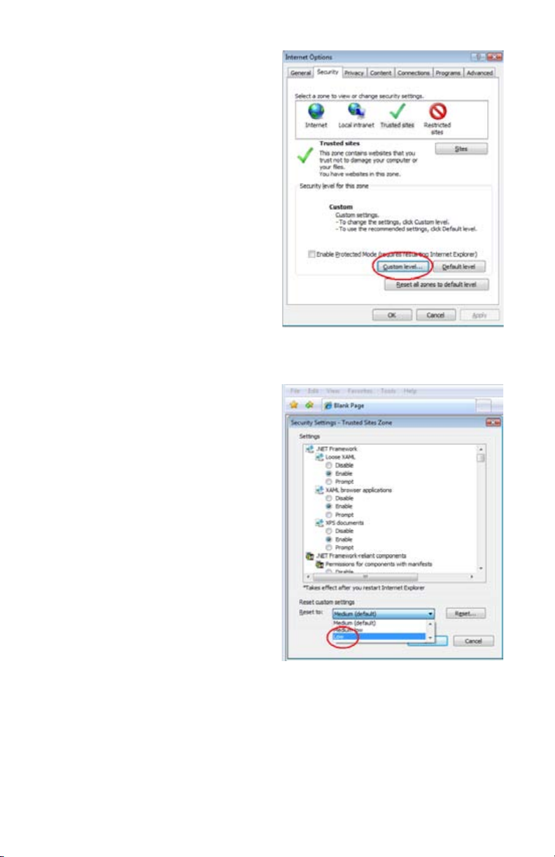
STEP 11. Click the Custom level…
button.
STEP 12. Pull down the “Reset to:”
menu button and select Low
PICTURE 7-52
64
PICTURE 7-53
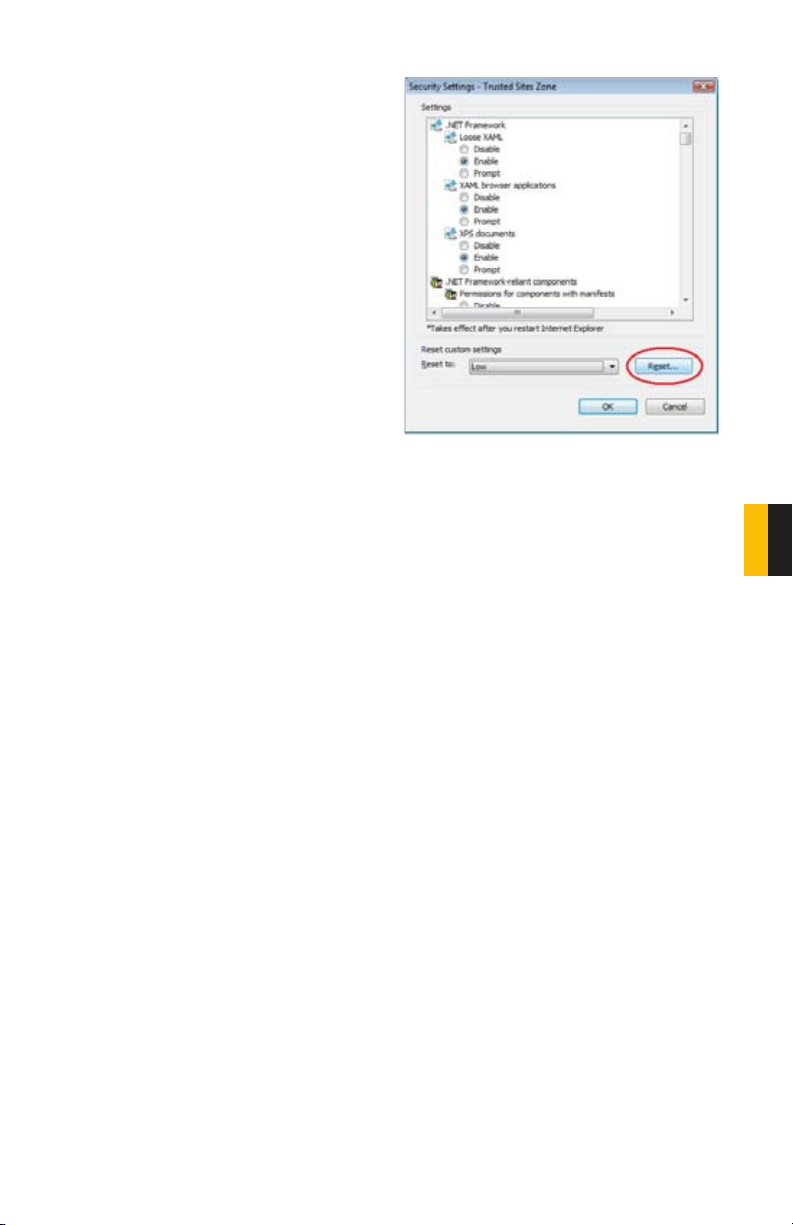
STEP 13. Click the Reset button
STEP 14. Click “Yes” when asked, “Are
you sure you want to change the
setting for this zone?”
STEP 15. Click OK
STEP 16. Click Apply
STEP 17. Click OK
STEP 18. Close Internet Explorer
PICTURE 7-54
You are now ready to access the DVR using Internet Explorer.
CHAPTER 7 REMOTE ACCESS
65
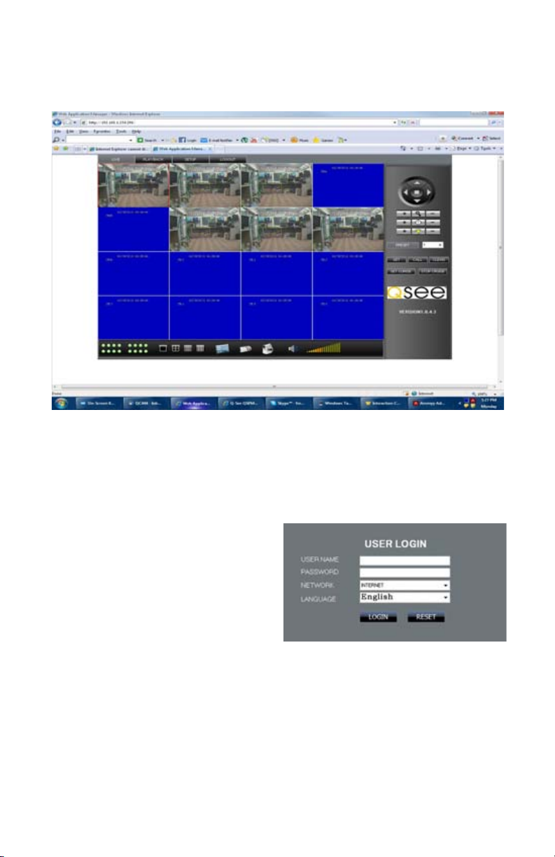
7.5 REMOTE SURVEILLANCE SOFTWARE
The system features a built-in browser-based software that allows you to access your system
remotely over your local area network (LAN) or over the Internet using Internet Explorer®.
PICTURE 7-55
The software will install the first time you access the DVR through Internet Explorer and will
allow you to operate the network remotely. The DVR supports access over LAN and WAN,
also supports IP and domain name access.
LOGGING IN REMOTELY
After you have installed the remote monitoring
software, any time you acces the DVR from
your computer you will have to sign onto the
DVR through the Login window.
Select LAN or INTERNET from the dropdown menu and click LOGIN. The process
will last for 1~2 minutes.
PICTURE 7-56
66
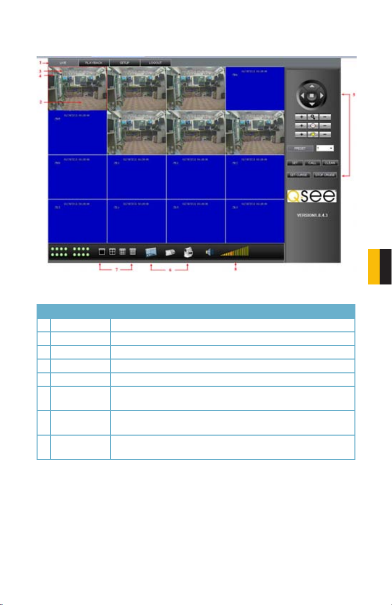
THE LIVE VIEW WINDOW
After logging in, the Remote Surveillance main screen will appear in your browser.
PICTURE 757
# Item Function
1 Modes LIVE, PLAYBACK, SETUP and LOGOUT.
2 Main Screen Main display screen for live viewing and playback.
3 Time Stamp Time stamp appears on each channel.
4 Channel Channel number appears in the top left corner.
5 PTZ Control PTZ control for any connected PTZ cameras (not included).
6 Functions Click the icons to show/hide channels, take screen captures, and
record.
7 Display Modes Click the icons to view channels in single-channel full-screen, quad,
and split-screen configurations.
8 Volume/Mute Select a channel (outlined in red) and then click the bars to increase/
decrease volume; click the icon to mute/un-mute volume.*
*Audio-capable cameras or powered microphones (not included) required for audio listening
and recording.
CHAPTER 7 REMOTE ACCESS
67
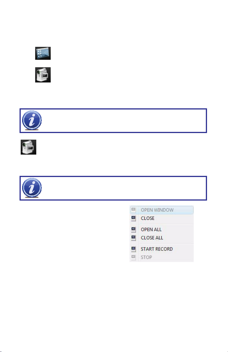
Live Viewing Controls
• Click LIVE at the top of the main screen.
• Click the display mode icons to view the main screen in single-channel, quad, or split-screen
configurations. You can also double-click a channel at any time to view it in single-channel.
• Click to show or hide all the channel windows.
• Click to start/stop manual recording to your PC on ALL channels. For more details
see RECORDING.
• Select a channel (outlined in red) and then click the audio bars to increase or decrease
listening volume. Click the icon to mute/unmute.
NOTE! The Talk function is not enabled on this DVR.
RECORDING
You can record video directly to your PC using the remote surveillance software.
To record video to your PC:
From Live viewing, click to start/stop manual recording to your PC on ALL channels
NOTE! You will record video to your PC regardless of the recording mode
on the system itself. By default, recorded files are saved in
C:\DVR\[ip_address]\Record.
SHORTCUT MENU
Right-click any channel to open the Shortcut
Menu.
68
PICTURE 7-58

PTZ CONTROL
You must have a PTZ camera (not included) connected to the system in order to use the PTZ
controls.
Controlling a PTZ Camera
• Select the channel of the connected PTZ
camera(s).
• Click the navigation arrows to pan and tilt
the camera.
• Click + /- to control zoom, focus, and iris.
• Enter presets.
• Click SETTING, HAND, and CLEAR to
further control presets.
PICTURE 7-59
SCREEN CAPTURES
Use the remote surveillance software to take a snapshot of the channels on the main display
screen. Screen Captures can be useful for your own records, or may be needed by authorities
in case of a security incident.
To take a screen capture:
STEP 1. In Live Viewing, select the channel you want to capture. The selected channel
will be highlighted in a red frame.
STEP 2. Click .
STEP 3. Click OK in the confirmation window.
Screen captures are saved as BMP files to the default save location (C:\DVR\...).
CHAPTER 7 REMOTE ACCESS
69
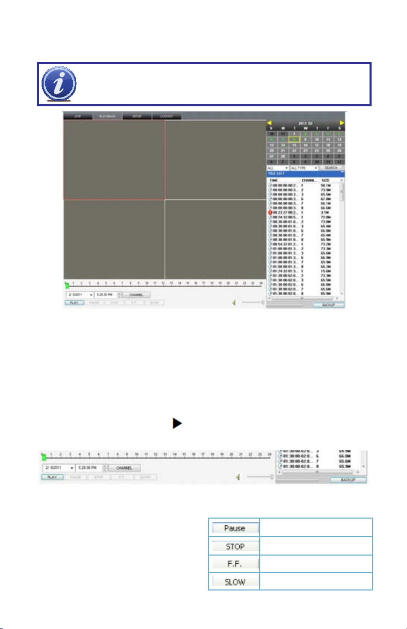
PLAYBACK
Use the Playback menu to search and playback recorded video on your system.
NOTE! When playing back video files online, you can only view a single
camera at a time.
PICTURE 7-60
To use the replay menu:
STEP 1. Click PLAYBACK at the top of the main screen. The main screen will be grey.
STEP 2. Click REFRESH below the calendar to view the recorded files for the current
month.
Normal recording is indicated by a clock icon; alarm recording (alarm, loss, and motion events)
are indicated by an exclamation mark icon.
STEP 3. Double-click a file from the File List to playback the file in the main screen. The
icon in the file list changes to “ ” .Control playback using the buttons at the bottom
of the main screen.
PICTURE 7-61
The blue bar above BACKUP indicates the
download progress. The green marker above
PLAY indicates playback progress. You
can click and drag the playback marker to
advance or rewind playback as needed.
Switch between pause/play
Stop play
Fast play
Slow play
70

SEARCH
Use the calendar and drop-down menus to search for recorded video on your system.
• Click < > to change the month on the
calendar. Dates with recorded video data will
appear in bold.
• Click the date. Recorded video files will
populate the File List.
• In the Channel drop-down menu, select a
specific channel or select ALL CHANNEL
and then click SEARCH.
• In the Type drop-down menu, select
COMMON (normal recording), ALARM, or
ALL TYPE and then click SEARCH.
• Double-click the file from the File List to
playback the file in the main screen.
CHAPTER 7 REMOTE ACCESS
PICTURE 7-62
71
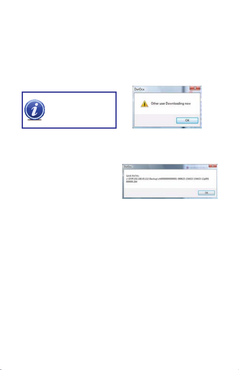
REMOTE BACKUP
You can backup recorded video files from your system to your PC using the Replay menu in
the remote surveillance software.
To backup files remotely:
STEP 1. Click REPLAY at the top of the main screen.
STEP 2. Select a date(s) on the calendar and click REFRESH.
STEP 3. Double-click a file from the File List to begin playback.
STEP 4. Click BACKUP. Backup begins to C:/DVR/[ip_address]/Backup
NOTE! If you play back a
file, you must wait for the file
to load before backing it up
otherwise you may receive an
error message.
PICTURE 7-63
When file backup is complete, click OK in the confirmation window. The confirmation window
will show the save path of the backup file.
The files will be saved with the .264 extension
and can be viewed with the Player software
included with your DVR. or available on our
website.
72
PICTURE 7-64
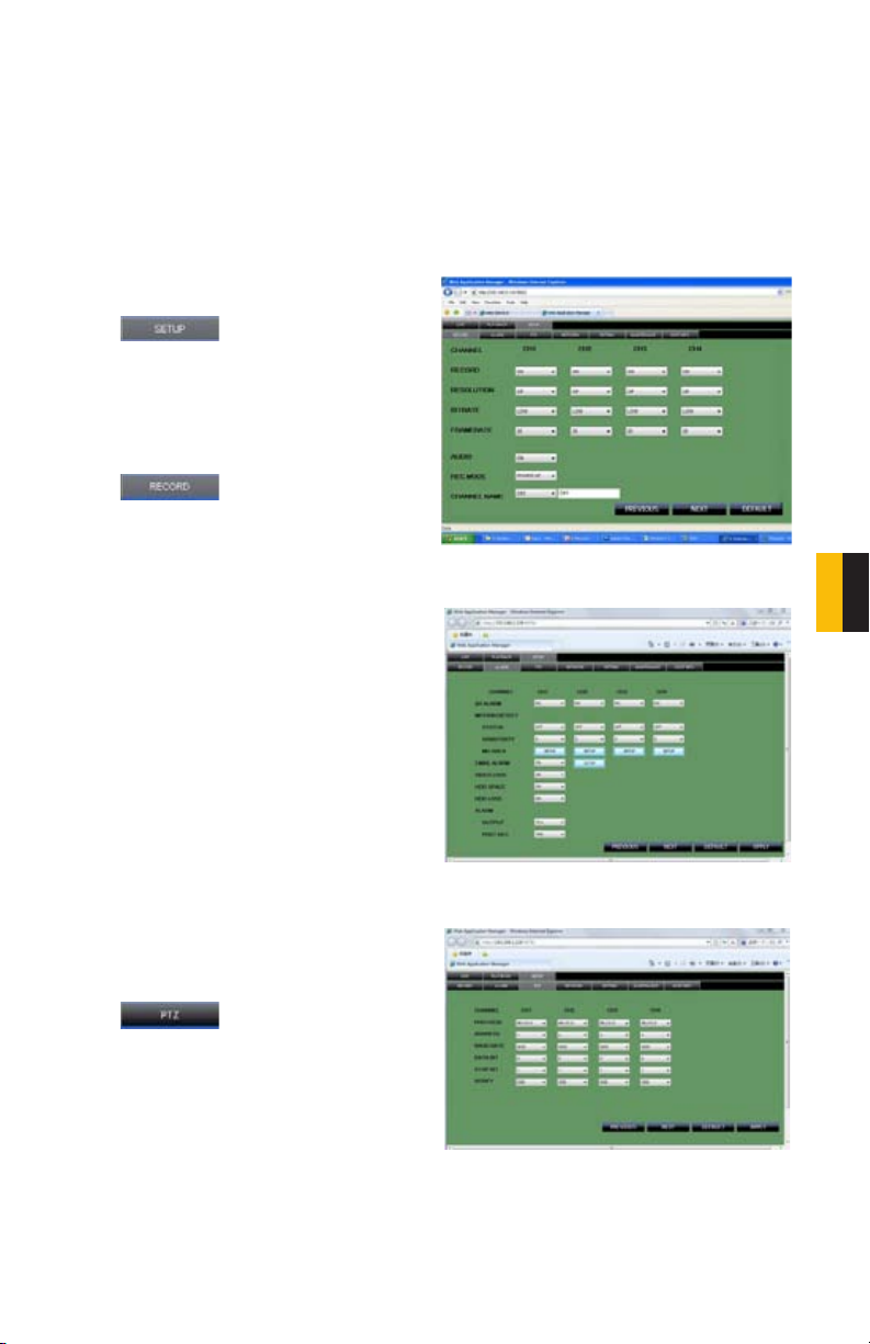
REMOTE SETUP
Use the Setup tab to configure the settings of your system from a remote location. If the Main
Menu is open on the system, you will not be able to make changes to the system from the
remote location.
Opening Remote Setup
Click SETUP at the top of the main screen. The Remote Setup menu features the following
tabbed options: Record, Alarm, PTZ, Network, Setting, Host Info
Click to enter into setup
interface, this interface include record, alarm,
PTZ, network, setting and system information
six menus.
Record
Click to enter into setup
interface; the parameter settings are the
same as on the DVR.
PICTURE 7-65
Alarm Setting
Click “ALARM” to enter into setup interface;
the parameter settings are the same as on
the DVR.
CHAPTER 7 REMOTE ACCESS
PTZ
Click to access setup interface;
the parameter settings are the same as on
the DVR.
PICTURE 7-66
PICTURE 7-67
73

Network
Click
the parameter settings are the same as on
the DVR.
Setting
Click
the parameter settings are the same as on
the DVR.
BANDWIDTH: Set the bandwidth in kbps (128k, 192k, 256k, 384k, 512k, 1024k) that you
want to allocate for traffic depending on the available internet bandwidth. This bandwidth does
not include audio.
FILE SAVE PATH: The save path of captured picture and recording video. IE login password
and DST settings you can set as DVR setting.
to access setup interface;
PICTURE 7-68
to access setup interface;
PICTURE 7-69
Maintenance
Click
interface; you can reboot DVR or remotely
upgrade firmware.
Host Info
Click to access system
information interface (see Figure 4.3.14). This
interface includes hard drive status, remaining
recording time, firmware version and MAC
Address. All the information is fixed, it cannot
be changed.
to access maintenance
74
PICTURE 7-70
PICTURE 7-71

7.6 MOBILE SURVEILLANCE
You can access your DVR from your cellular phone running Windows Mobile Pro (6.0 or
later), Symbian (S60 3rd or later), Android, Blackberry (Curve 8900, Bold 9700, Tour 9630),
or iPhone on 3G networks. The instructions on how to install and use the software for the
different phone operating systems is on the CD included with the DVR. This CD also includes
the software needed for Windows Mobile Pro, Symbian, Android, and Blackberry. To use with
an iPhone you need to download the software from the iTunes app store. The installation and
operating instructions for each type of phone are included on the CD included with the DVR.
NOTE! Before you can use mobile access you need to setup the network
configuration on the DVR and forward ports 80, 100, and 9000 from the
router the DVR is attached to, to the IP address of the DVR as described in
Section 7.2.
The Mobile Setup window is found in the
Advanced Menu.
PICTURE 7-72
CHAPTER 7 REMOTE ACCESS
To configure mobile notification settings:
STEP 1. Under MOBILE NETWORK,
select 3G
STEP 2. Under MOBILE PORT, enter
your mobile port number.
STEP 3. Click APPLY. Click CLOSE in
the confirmation window.
PICTURE 7-73
75

HARD DRIVE INSTALLATION
WARNING! ELECTRIC SHOCK RISK!
The DVR MUST be unplugged from all power sources as well
as from the cameras before opening the case. Failure to do so
can result in damage to the DVR or its components as well as
injury or death.
It is strongly advised against opening the case when atmospheric conditions present the risk
of static discharge which can damage electronic components. Please follow these steps to
install the hard drive:
STEP 1. Open the cover of the DVR.
STEP 2. If replacing a hard drive,
unscrew the four mounting screws
on the underside of the DVR which
secure the drive to the base of the
DVR.
CHAPTER 8
STEP 3. Connect HDD cables as shown
below:
STEP 4. Attach HDD to base of the DVR
with the screws provided.
STEP 5. After installing HDD into DVR
close cover.
NOTE! The newly-installed hard drive will need to be formatted before it can
record.
76

APPENDIX
PRODUCT SPECIFICATIONS
ITEM DEVICE
PARAMETER
SYSTEM LANGUAGE ENGLISH/ CHINESE
GUI GRAPHIC MENU (OSD MENU)
PASSWORD ADMINISTRATOR PASSWORD, USER
VIDEO VIDEO IN 8 CH (QS408) 16 CH (QS206) COMPOSITE VIDEO
VIDEO OUT 1 CH COMPOSITE VIDEO OUTPUT, BNC, VGA
VGA OUTPUT 800x600, 1024x768, 1280x1024, 1366x768,
VIDEO DISPLAY 1/4/9/16 CHANNEL SWITCH, QUAD DISPLAY
VIDEO STANDARD CIF PAL, 25F/S, CCIR625LINE, 50SCENE
AUDIO AUDIO INPUT 2 CH (QS206) 8 CH (QS408) AUDIO INPUT,
AUDIO OUTPUT 1 CH AUDIO OUTPUT, IMPEDANCE600Ω, RCA
BASIC
ELECTRICITY
OUTPUT
RECORD STYLE AUDIO VIDEO RECORDED SIMULTANEOUSLY
AUDIO
COMPRESSION
PICTURE
PROCESSING
AND
STORAGE
PICTURE
COMPRESSION
PICTURE
RESOLUTION
STREAMING STYLE ISO14496-10
AUDIO STYLE ADPCM
VIDEO CODE RATE CIF: 384~768 KBPS (NORMAL)
AUDIO CODE RATE 32KB/S
DATA STORAGE 1 SATA HDD UP TO 2TB (OPTIONAL) QS206
PASSWORD
INPUT 1.0VP-P, IMPEDANCE75Ω, BNC
1440x900
(16 Channel on QS206 only)
CIF NTSC, 30F/ S, CCIR525LINE, 60SCENE
IMPEDANCE600Ω, RCA
LINEARITY ELECTRICITY
8khz 16bit ADPCM
H.264
QS206 CIF (352x240)
QS408 CIF (352x240) D1 (702x480)
CIF:512 KBPS (HIGH)
CIF: 768 KBPS (HIGHEST)
1 SATA HDD UP TO 1TB (OPTIONAL) QS408
SPECIFICATION
77

CONNECTOR NETWORK
ITEM DEVICE
ALARM ALARM INPUT 4 ALARM INPUTS (QS206)
ALARM I/O VOLTAGE 0-2V, low voltage, 5-30V high voltage
CONNECTOR ALARM OUTPUT 2 ALARM OUTPUTS (QS206)
Backup USB
2.0
SOFTWARE
UPGRADE
OTHERS VOLTAGE INPUT AC:110~240V
INTERFACE
PARAMETER
SERIAL INTERFACE SUPPORT 1 RS232
PTZ INTERFACE SUPPORT 1 RS485 (PelcoD, PelcoP)
NETWORK
INTERFACE
USB Mouse USB 1.1
SUPPORTS
USB FIRMWARE
UPGRADE
VOLTAGE OUTPUT DC: 12V@5A
POWER
CONSUMPTION
WORKING
TEMPERATURE
RJ45,10M/100M
SPECIFICATION
8 ALARM INPUTS (QS408)
1 ALARM OUTPUT (QS408)
RJ45, 10M/100M
6W WITHOUT HDD
50 TO 104°F (10 TO 40C)
BASIC OPERATIONAL SPECIFICATIONS
ITEM PARAMETER DESCRIPTION
VOLTAGE INPUT 12V DC 12V 5AMP (QS206)
DC 12V 3AMP (QS408)
VIDEO IMPEDANCE INPUT 75Ω 75Ω Each Channel
VIDEO OUTPUT 1V P-P 1V P-P CVBS Signal
SATA HDD 1 SATA UP TO 2TB (QS206)
UP TO 1TB (QS408)
with mainstream capability
WORKING TEMPERATURE 50 TO 104°F (10 TO 40°C)
78

FREQUENTLY ASKED QUESTIONS
If your problem is not listed below, please check our Resource Center at http://q-see.com/
glossary/resource-library.php go to live chat at http://q-see.com or call our toll-free
number, 877-998-3440 for more support.
Question 1: Why is the DVR not working after starting?
Answer:
• Check the power adaptor input
• Check the power on-off
• Check the main board of the DVR
Question 2: Why is the DVR rebooting automatically or stopping for several minutes
after starting?
Answer:
• Instability or low input voltage
• Bad track on hard drive or the hard drive is bad
• Power supply is not producing enough power
• The front-end video signal is not stable
• High temperature, too much dust, bad DVR operating environment
• There is a problem with the connector on the main board
• The main board of the DVR is defective
Question 3: Why is there no video output on single channel, multi channel or all
channels?
Answer:
• Please check the camera cable connection to verify it is well-connected
• Please check the cable connection video on the back panel of DVR
• Please connect the camera directly to a TV to see if you get picture
• Check the brightness of the picture and bring it back to its original default setting
• The main board of the DVR is defective
Question 4: DVR cannot record after startup and the interface is showing “H”, why?
Answer:
• Make sure power adaptor is DC 19V
• Make sure hard drive is formatted
• Check the power and data connection cables of the hard drive
• The hard drive is defective
• The SATA port is not working
Question 5: What is the meaning of“R”“M”“I”“H” showing on the screen?
Answer:
• “R”means the channel is recording
• “M” means the channel is on motion detection
• “I”means the channel is on alarm
• “H” means there is either no HDD. the HDD is bad or the HDD is full
79

Question 6: DVR is having problems with real-time images, such as bad image color or
serious brightness distortion, why?
Answer:
• If PAL and NTSC is not correctly selected on the BNC output, the images will be in black
and white
• DVR is not compatible with monitor
• The video transmission distance is too far
• The DVR color, brightness, etc. settings need to be adjusted
Question 7: Why don’t I have audio when monitoring?
Answer:
• Check sound box or speaker functions. Also check for possible short circuit.
• Audio source may be connected to the video channel. You can click to full-screen to
check.
• The main board of the DVR is defective
Question 8: Why don’t I have audio when playing back?
Answer:
• Setting problem: open audio-video item
• Check the audio to see if it is closed in playback interface
Question 9: Why is my System time not correct?
Answer:
• Wrong setting or user did not click “Edit” to confirm
• Battery is not connected properly
• Battery is dead and needs to be changed
Question 10: Why does the “Stop recording” by the right mouse button not work?
Answer:
• The “Stop recording” by the right mouse button is only suitable for Manual recording. It
can’t stop recording when recording on a set schedule or on motion recording
Question 11: Why is Motion detection not working?
Answer:
• The settings in the motion detection area is not correct
• Sensitivity is too low
Question 12: Why is the USB device giving me a backup error?
Answer:
• The data exceeds the capacity of backup device
• The backup device is incompatible
• The backup device is damaged
Question 13: Why does the Remote Control not work?
Answer:
• The address of remote control is not correct
• The distance of remote control is too far or the angle is too wide
• Remote control batteries are low
• Remote control is damaged or the front panel of DVR is damaged
80

Question 14: Why can’t I log in over the Internet?
Answer:
• Please check the network to see if it is connected. Check if LINK or 100M LED is
displayed on the front panel; use ping xxx.xxx.xxx.xxx (DVR IP) to check if the Internet is
linked properly
• Make sure you are running Windows XP, Vista, or Win7 operating system, and IE6.0-8.0
browser
• ActiveX control has been blocked. Please manually install ActiveX control again
• Please install DX8.1 and upgrade your video card driver
Question 15: Why is there is no picture or picture is not clear when you preview the
recording or playback the recording via IE?
Answer:
• If you access DVR by IE, please choose “Wan” in “web environment”
• Please try “Close windows” by the right mouse button, and try “Open windows” again
Question 16: Why am I receiving a message indicating “other members are setting......”
when accessing my DVR settings through Internet Explorer?
Answer:
• It probably means someone else is changing the settings of the DVR. Please check the
DVR configuration interface or exit the DVR
81

82

Q-SEE PRODUCT WARRANTY
Q-See is proud to back all of our products with a conditional service warranty covering all
hardware for 12 months from the date of purchase. Additionally, our products also come with
a free exchange policy that covers all manufacturing defects for one month from the date of
purchase. Permanent upgrading service is provided for the software.
Liability Exclusions:
Any product malfunction or abnormalities in operation or damage caused by the following
reasons are not within the free service scope of our company:
1. Equipment damage caused by improper operation.
2. Improper equipment operation environment and conditions (e.g., improper power,
extreme environmental temperatures, humidity, lightning and sudden surges of
electricity).
3. Damage caused by acts of nature (e.g., earthquake, fire, etc).
4. Equipment damage caused by the maintenance of personnel not authorized by Q-See.
5. Product sold over 12 months ago.
In order to fulfill the terms of your warranty, you must complete the registration process after
purchasing our product. To do this, simply fill out the User’s Information Card on our website
at www.Q-See.com
83

QUESTIONS OR COMMENTS? CONTACT US
MAILING ADDRESS
Q-See Products
Digital Peripheral Solutions, Inc.
8015 E. Crystal Drive
Anaheim, CA 92807
FAX
714-998-3509
WEBSITE
www.Q-See.com
PRODUCT SUPPORT, DOWNLOADS,
FIRMWARE UPDATES
& MANUALS
www.Q-See.com
CUSTOMER SUPPORT
Live Chat at www.Q-See.com (M-F, 9-5 PST)
Email: cs@dpsi-usa.com
Phone: 877-998-3440 (M-F, 9-5 PST)
84

Digital Peripheral Solutions, Inc.
8015 E. Crystal Drive
Anaheim, CA 92807
85
 Loading...