


Error! Use the Home tab to apply
标题
1 to the text that you want to
you want to appear here.
appear here. Error! Use the Home
tab to apply 标题 1 to the text that
1.1 Summarization ............................................................................................... 5
1.2 System Requirements ................................................................................... 7
1.2.1 QSDT4PCRC/QSDT4PCRP Card System Requirements .............................................. 7
1.2.2 QSDT8PCRP Card System Requirements
1.2.3 QSP D 4116 Card System Requirements
1.3 System Specifications .................................................................................. 10
2.1 Video Capture Card Hardware
2.1.1 QSDT4PCRC Card Hardware ....................................................................................... 11
2.1.2 QSDT4PCRP Card Hardware
2.1.3 QSDT8PCRP Card Hardware
2.1.4 QSPD4116 Card Hardware
2.1.5 Alarm Board Hardware
2.1.6 Connect Audio Signal
2.2 Install Video Capture Card Driver ................................................................ 18
3.1 Display Control Panel
3.1.1 Display Control Panel .................................................................................................. 22
3.1.2 Display Modes
3.1.3 Flip Pages
3.1.4 Auto Dwell Display Mode
3.1.5 Capture
3.1.6 Urgent Record
3.2 Login ............................................................................................................ 23
3.3 Record
3.3.1 Record Modes ............................................................................................................. 24
3.3.2 Rec ord Setup
3.3.3 Record Status Panel
3.3.4 Manual Record Mode
3.3.5 Se nsor Alarm Record M ode
3.3.6 Motion Detection Record Mode
3.3.7 Schedule Rec o rding
3.3.8 Recycling Recordings
4.1 Basic Configuration ..................................................................................... 28
4.2 Video Configuration ..................................................................................... 30
4.3 Motion Detection Configuration
4.3.2 Set Motion Detection Area ........................................................................................... 32
4.3.3 Clear Motio n D etection Area
4.4 Schedule Configuration ............................................................................... 33
4.5 Motion Detection Alarm Configuration
4.5.1 Alarm Triggering Conditions Configuration ................................................................... 34
4.5.2 Alarm Record
4.5.3 Alarm Output
4.5.4 Auto Mail Function
4.6 E-map Configuration .................................................................................... 38
4.6.1 Ed it M ap ...................................................................................................................... 38
4.6.2 Vie w Map
4.7 P.T.Z Control Configuration .......................................................................... 41
4.7.1 Pr otocol Setup ............................................................................................................. 41
4.7.2 Serial Ports Setup
4.8 Users Configuration ..................................................................................... 43
4.8.1 Change User rights ...................................................................................................... 43
4.8.2 Add User
SuperDVR & H.264 Series Cards
User Manual
CONTENTS
..................................................................... 8
......................................................................... 9
..................................................................... 11
...................................................................................... 12
...................................................................................... 14
.......................................................................................... 15
................................................................................................ 17
.................................................................................................. 17
.................................................................................. 22
............................................................................................................. 22
................................................................................................................... 22
............................................................................................. 23
....................................................................................................................... 23
............................................................................................................. 23
......................................................................................................... 24
.............................................................................................................. 24
.................................................................................................... 25
.................................................................................................. 26
......................................................................................... 26
.................................................................................... 26
.................................................................................................... 27
.................................................................................................. 27
................................................................... 31
........................................................................................ 32
......................................................... 34
............................................................................................................... 35
............................................................................................................... 35
....................................................................................................... 36
.................................................................................................................... 39
........................................................................................................ 42
..................................................................................................................... 44
2

Error! Use the Home tab to apply
标题
1 to the text that you want to
you want to appear here.
SuperDVR & H.264 Series Cards
User Manual
4.8.3 Delete User ................................................................................................................. 44
5.1 P.T.Z Control ……………………………………………………………………
Error! Bookmark not defined.
6.1 Record Search
6.2 Playing Back and Control ............................................................................ 50
6.3 Other Functions
6.3.1 Recorded File Backup ................................................................................................. 53
6.3.2 Delete Recorded Files
6.3.3 Capture Pictures
6.3.4 Image Zoom in/out
Remote Live Surveillance .................................................................................. 59
7.1 Remote Surveillance Server Configuration
7.2 Setting up Router for Internet Access
7.2.1 Port Forwarding ........................................................................................................... 61
7.2.2 Finding Router’s Public IP address
7.2.3 Dyn amic Domai n Name Services
7.2.4 To Access through Internet Explorer
7.2.5 Unknown Publisher or Unsigned Program Error
7.3 Accessing IE client ....................................................................................... 65
7.4 Remote playback
7.4.1 Record playback and control ........................................................................................ 69
7.5 System setup ............................................................................................... 72
7.5.1 Basic Configuration ...................................................................................................... 73
7.5.2 Camera setup
7.5.3 Schedule configuration
7.5.4 Alarm configuration
7.5.5 Record configuration
7.5.6 Motion configuration
7.5.7 EMAIL Configuration
7.5.8 P.T.Z Configuration
7.6 Mobile Surveillance ..................................................................................... 83
7.6.1 Introduction to Mobile Surveil lance ............................................................................... 83
7.7 By Smart Phone with Win Mobile Pro or Classic Operating System ............ 83
7.8 By Smart Phone with Symbian Operating System ....................................... 86
Appendix1 Frequently Asked Questions ....................................................... 90
Appendix 2.1 Installation
Appendix 2.1.1 Cannot Install the SuperDVR Driver ............................................................. 90
Appendix 2.1.2 Can’t find H.264 series Devices in Device Manager
Appendix 2.2 How to Use SuperDVR ................................................................ 90
Appendix 2.2.1 Meanings of the indicator lights .................................................................... 90
Appendix 2.2.2 How do the different record modes work?
Appendix 2.2.3 How to set recycling record mode on the system
Appendix 2.2.4 How to set aut o reboot func tion
Appendix 2.2.5 How to quickly setup the schedule record function
Appendi x 2.2.6 What are the byte rates for different image qualities from highest to normal?
Appendi x 2.2.7 The fram e rate seems t o be lower than what I set
Appendix 2.2.8 Why can’t I select more channels to backup?
Appendix 2.3 How to Use Network Function ..................................................... 92
Appendix 2.3.1 How to monitor on the client-side .................................................................. 92
Appendix 2.3.2 Why can’t I download the client-side sof tware?
Appendix 2.3.3 Why can’t the server be configured at the client-side?
appear here. Error! Use the Home
tab to apply 标题 1 to the text that
............................................................................................. 50
........................................................................................... 53
................................................................................................. 54
.......................................................................................................... 55
....................................................................................................... 57
.................................................. 59
.......................................................... 60
.............................................................................. 62
................................................................................. 63
............................................................................. 63
........................................................... 65
......................................................................................... 69
.............................................................................................................. 74
................................................................................................ 75
...................................................................................................... 76
.................................................................................................... 77
.................................................................................................... 78
.................................................................................................... 79
...................................................................................................... 81
................................................................................... 90
...................................... 90
..................................................... 90
.......................................... 91
.................................................................... 91
........................................ 91
91
......................................... 91
............................................... 91
............................................. 92
.................................. 92
3

Error! Use the Home tab to apply
标题
1 to the text that you want to
you want to appear here.
appear here. Error! Use the Home
tab to apply 标题 1 to the text that
Appendix 2.3.4 Why can’t I see the images? ......................................................................... 92
Appendix 2.3.5 What should I do if the Internet speed is quite slow?
Appendix 2.3.6 Why can’t I start Webcam server or RPB ser ver ?
Appendix 2.3.7 How much hard dr iv e space do the recorded f iles take up?
Appendix 2.4 Other Questions .......................................................................... 94
Appendix 2.4.1 Why doesn’t the computer display work, or why can’t I access Window system?
Appendix 2.4.2 Why I can’t find the recorded files?
Appendix 2.4.3 Why is the screen’s display unstable with dithering and water-wave images?
Appendix 2.4.4 Why does it delay playing back, and why is it slow to close and open the driver?
Appendix 2.4.5 Why can’t I play back?
Appendix 2.4.6 Why do I see some gray blocks on time progress bar area when playing back?
Appendix 2.4.7 Why could I see some old recording sections that weren’t available for play
back?
Appendi x 2.4.8 Prec autions on c hanging system time
Appendix 2.4.9 If system time must be changed, please do follow ing preparations first
Appendix 2.4.10 How to use REPAIRDB to repair SuperDVR database
Appendix 2.4.11 How to set power options of Microsoft VISTA system
Appendix2 Quick Start for Using ................................................................. 96
Appendix 3.1 Installation Instructions
Appendix 3.2 T r ouble shoo tin g
Appendix3.2.1 When opening the SuperDVR program, it says ‘ Can’t find card ’. ............... 97
Appendix 3.2.2 How to setup the web client to monitor from Internet
Appendix3 Function Tree ............................................................................. 99
Appendix 4.1 SuperDVR Function Tree
Appendix 4.2 System Configuration Tree
Appendix 4.3 IE Client FunctionTree
Appendix 4.4 Remote Playback Function Tree
SuperDVR & H.264 Series Cards
User Manual
..................................... 93
......................................... 93
........................... 93
............................................................................................................................................ 94
............................................................... 94
94
............................................................................................................................................ 94
................................................................................. 95
............................................................................................................................................ 95
................................................................................................................................... 95
.......................................................... 95
......... 96
................................ 96
.................................. 96
................................................................ 96
........................................................................... 97
..................................... 97
............................................................. 99
........................................................ 100
............................................................... 101
................................................ 102
4

SuperDVR & H.264 Series Cards
Error! Use the Home tab to apply
标题
you want to appear here.
User Manual
1.1 Summarization
Thank you for choosing our digital video capt ure car ds.
4 Channel, 8 Channel and 16 Channel cards adopt H.264 compression form at,
and enable a maximum of 16 c hannels re al-time surv eillance in CIF resolution.
Our cards are mature and cost-effective products that should be your ideal
choices. They enable synchronous audio and video compression and
transmission along with their powerful compression rate and network
transmission function. They are widely used in banks, intelligent communities,
traffic management units, medical systems, educational systems, armed
forces and so on.
This manual is suitable for SuperDVR 6.2, which supports QSDT4PCRC,
QSDT4PCRP, QSDT8PCRP, and QSPD4116 cards.
In this manual, you will learn how to ins t al l t he hardware and driver (software),
and how to setup the systems on this range of products. Please make sure
your operations with the products are strictly in accordance with the manual,
to maintain the sta bil ity of the digital surveillance systems.
The following are standard functions of these products:
• Schedule record mode
Users can choose any period in a day to record and set up record modes,
i.e. sensor alarm record, motion detection record, manual record,
Schedule Record.
• Motion detection mode
Motion detection areas are adjustable with a maximum 16 areas for each
channel. Users can also set motion detection sensitivity for each channel.
The system begins to record only when motion is detected is detected on
the channel and af ter motion stops it will stop recording af ter a certain time
period, which is adjustable by users.
• Sensor alarm record mode
The system has an external alarm which enables the system to support
alarm input and output.
• Recycling record mode
Users can set recording storage sequence for HDD partitions. The
recording storage will automatically switch to the next partition when the
current one is full. If all t he parti ti ons ar e fu ll an d recyc lin g rec or d mod e is
enabled, the oldest recorded data will be covered by new data. Users can
also set HDD minimum storage alarm. Then once the present storage
1 to the text that you want to
appear here. Error! Use the Home
tab to apply 标题 1 to the text that
1 Introduction
5

Error! Use the Home tab to apply
标题
1 to the text that you want to
you want to appear here.
appear here. Error! Use the Home
tab to apply 标题 1 to the text that
space is less then the minimum storage and recycling record mode is not
enabled, recording will automatically stop.
• P.T.Z control function
Supports a number of protocols. Users can control multiple speed domes
and integrative cameras, including pan, tilt, zoom, focus and iris
adjustment for P.T.Z devices. Supports preset points and auto scout.
• User management
Different users have different rights, user names and passwords, to
ensure system security.
• Multi-channel display
Supports different multi-channel display modes, full screen display and
auto dwell display.
• Watch dog function
The 16 Channel card has watchdog function. In case SuperDVR driver or
Windows system is frozen, the watchdog will restart the computer and
login to SuperDVR system again automatically.
• One PC can contain 1 to 4 cards of the same model, up to a total of 32
channels
• Supports 320x240 (NTSC), 352x288 (PAL) standard resolutions.
• Im age color is adjustable for each channel, including contrast, brightness,
hue and saturation.
• H.264 compression format greatly reduces HDD usage.
• Powerful video playback functions, including playing back, pause, stop,
fast-forward, single-fram e play and image captur e.
• Supports advanced search mode. Users can search by date/time, camera,
record mode, and random combination of the three methods.
• Supports recorded file backup, delete by date/time, camera.
• Conveniently extend system functions through software upgrades.
• Supports multiple languages, including Chinese (Traditional), English,
German, Spanish, Portuguese and other customized languages.
• CPU and storage resource saving by advanced technology
• Remote Surveillance and P.T.Z control through LAN, Intranet, and
Internet.
• Supports alarm pre-record.
• Supports buzzer, email alarm out.
• Can greatly decrease fragmented files while using NTFS partiti on.
• User-friendly graphical user interface.
SuperDVR & H.264 Series Cards
User Manual
6

Error! Use the Home tab to apply
标题
1 to the text that you want to
you want to appear here.
PC Module
Supports MOST* AGP and PCI-E Video Cards
NVIDIA GeForce 8500GT
SuperDVR & H.264 Series Cards
User Manual
appear here. Error! Use the Home
tab to apply 标题 1 to the text that
1.2 System Requirements
Our H.264 series car ds s upport video cards on Windows VISTA as long as the computer that the card is installed in supports Vista, and Vista supports the video card being used.
1.2.1 QSDT4PCRC/QSDT4PCRP Card System Requirements
Card
CPU Intel P4 processor 2.0G minimum
HDD 100Gb minimum free space
RAM 512MB minimum
QSDT4PCRC/QSDT4PCRP
VIDEO CARDS
OS (32 bit) Win2000 /WinXP /VISTA
DirectX 9.0
Table1-1 QSDT4PCRC/QSDT4PCRP System Requirements
NOTICE
1. Motherboards listed below which have passed our testing and work well with
QSDT4PCRC/QSDT4PCRP:
• Intel 865G
• GA-945PL-S3E
• GA965P-S3
• GA-K8V7890-9
• GA-8IE2004P
• ASUS P5PL2
• ASUS P5B-E
2. VGA cards listed below which have passed our testing and work well with
QSDT4PCRP:
• ATI X1600
• ATI X300
• NVIDIA GeForce 7300LE
• NVIDIA GeForce 7600GS
•
with 64MB of RAM or more with full Direct Draw support.
*Some ne wer PCI-E cards are not yet supported
NOTE: If recorded disk partition’s format is FAT32 and the system has
run for a long time, the system will create a lot of data fragments that
may result in system running slowly. It’s recommended to run a disk
defragmenter every 10 to 30 days. We strongly suggest that you use
NTFS format for recording disk partition.
7

Error! Use the Home tab to apply
标题
1 to the text that you want to
you want to appear here.
Card
PC Module
Supports MOST* AGP and PCI-E Video Cards
Motherboard
Video card
ATI HD2400
NVIDIA GeForce 7600
NVIDIA GeForce 7300
ATI HD2400
ATI X300
ATI HD2400
NVIDIA GeForce 7600
NVIDIA GeForce 7300
ATI X300
ATI HD2400
NVIDIA GeForce 7300
ATI X300
ATI HD2400
NVIDIA GeForce 7600
ATI X300
ATI HD2400
NVIDIA GeForce 7600
ATI X300
ATI HD2400
NVIDIA GeForce 7600
ATI X300
ATI X700
Motherboard
Video card
COLORFUL C975X-MVP
ATI HD2400
appear here. Error! Use the Home
tab to apply 标题 1 to the text that
1.2.2 QSDT8PCRP Card System Requirements
CPU Intel P4 processor 2.0G minimum
HDD 200GB minimum free space
RAM 512M minimum
SuperDVR & H.264 Series Cards
User Manual
QSDT8PCRP
VIDEO CARDS
OS (32 bit) Win2000/WinXP/VISTA
DirectX 9.0
with 64MB of RAM or more with full Direct Draw support.
*Some ne wer PCI-E cards are not yet supported
Table1-2 QSDT8PCRP System Requirements
Motherboards and V ideo cards listed below have passed our testing and work
well with QSDT8PCRP in Windows XP systems:
COLORFUL C975X-MVP
ASUS P5LD2-X
ASUS P5B
GA-965P-S3
GA-945PL-S3E
ASUS P5L-1394
ASUS P5GD1-VM
Table1-3 Motherboards and Video Cards Supporting XP
Motherboards and Video cards listed below which have passed our testing
and work well wit h QSPD4116 in Windows VISTA systems:
8
Error! Use the Home tab to apply
标题
1 to the text that you want to
you want to appear here.
Motherboard
Video card
ATI HD2400
ATI X300
ATI HD2400
ATI X300
ATI HD2400
ATI X300
ATI HD2400
ATI X300
ATI X700
Card
PC Module
Motherboard
Video card
ATI HD2400
NVIDIA GeForce 7600
NVIDIA GeForce 7300
ATI HD2400
ATI X300
ATI HD2400
NVIDIA GeForce 7600
NVIDIA GeForce 7300
ATI X300
ATI HD2400
NVIDIA GeForce 7300
ATI X300
ATI HD2400
NVIDIA GeForce 7600
ATI X300
ATI HD2400
NVIDIA GeForce 7600
ATI X300
ATI HD2400
NVIDIA GeForce 7600
SuperDVR & H.264 Series Cards
User Manual
ASUS P5LD2-X
GA-965P-S3
ASUS P5L-1394
ASUS P5GD1-VM
Table1-4 Motherboards and Video Cards Support VISTA
appear here. Error! Use the Home
tab to apply 标题 1 to the text that
1.2.3 QSPD4116 Card System Requirements
QSPD4116
CPU Intel P4 processor 2.0G minimum
HDD 200GB minimum free space
RAM 512MB minimum
Supports MOST* AGP and PCI-E Video Cards
VIDEO CARDS
OS (32 bit) Windows 2000/WinXP/VISTA
DirectX 9.0
with 128MB of RAM or more with full Direct Draw support.
*Some ne wer PCI-E cards are not yet supported
Table1-5 QSPD4116 System Requirements
Motherboards and Video cards listed below which have passed our testing
and work well wit h QSPD4116 in Windows XP system:
COLORFUL C975X-MVP
ASUS P5LD2-X
ASUS P5B
GA-965P-S3
GA-945PL-S3E
ASUS P5L-1394
ASUS P5GD1-VM
9

Error! Use the Home tab to apply
标题
1 to the text that you want to
you want to appear here.
Motherboard
Video card
ATI X300
ATI X700
Motherboard
Video card
COLORFUL C975X-MVP
ATI HD2400
ATI HD2400
ATI X300
ATI HD2400
ATI X300
ATI HD2400
ATI X300
ATI HD2400
ATI X300
ATI X700
appear here. Error! Use the Home
tab to apply 标题 1 to the text that
Table1-6 Motherboards and Video Cards Supporting XP
SuperDVR & H.264 Series Cards
Motherboards and Video cards listed below which have passed our testing
and work well wit h QSPD4116 in Windows VISTA system:
ASUS P5LD2-X
GA-965P-S3
ASUS P5L-1394
ASUS P5GD1-VM
User Manual
Table1-7 Motherboards and Video Cards Supporting VISTA
1.3 System Specifications
• Format: PAL/NTSC.
• Resolution: 320x240 (NTSC), 352x288 (PAL).
• Maximum Frame rate per channel: 25 fps (PAL), 30 ftp (NTSC). Screen
set: resolution 1024×768, color quality 16 bits or 32 bits.
• Compression code rate: 50kbps – 1.2Mbps.
• Data format: H.264.
10

SuperDVR & H.264 Series Cards
Error! Use the Home tab to apply
标题
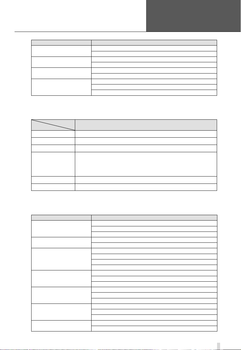
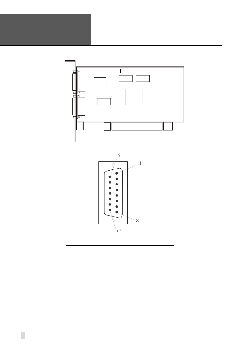
Pin Port
Definition
Interpret
1PIN
5V
Power Source (5V)
2PIN
ALARM_COM
Alarm COM
3PIN
ALARM_NC
Alarm Normal Close
4PIN
ALARM_IN1
Alarm Input 1
5PIN
ALARM_NO
Alarm Normal Open
6PIN
ALARM_IN2
Alarm Input 2
7PIN
GND
Ground
8PIN
ALARM_IN3
Alarm Input 3
9PIN
GND
Ground
10PIN
ALARM_IN4
Alarm Input 4
User Manual
2.1 Video Capture Card Hardware
2.1.1 QSDT4PCRC Card Hardware
1 to the text that you want to
appear here. Error! Use the Home
tab to apply 标题 1 to the text that
you want to appear here.
2 Hardware Installation
Figure2-1 QSDT4PCRC Video Capture Card
Table2-1 QSDT4PCRC Card Pins
11
Error! Use the Home tab to apply
标题
1 to the text that you want to
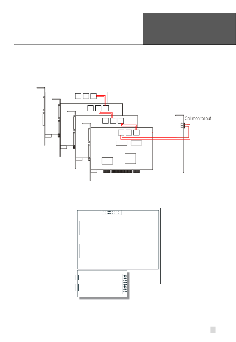
PIN1
AUDIO-1
PIN2
GND
PIN3
AUDIO-2
PIN4
GND
PIN5
AUDIO-3
PIN6
GND
PIN7
AUDIO-4
PIN8
GND
J5
E 1 2 3 4
6
7
appear here. Error! Use the Home
tab to apply 标题 1 to the text that
you want to appear here.
2.1.2 QSDT4PCRP Card Hardware
SuperDVR & H.264 Series Cards
User Manual
Figure2-2 QSDT4PCRP Video Capture Card
GiL-G-8P-S3T2-
5
8
Figure2-3 Definition of Audio Connector’s Pins
12
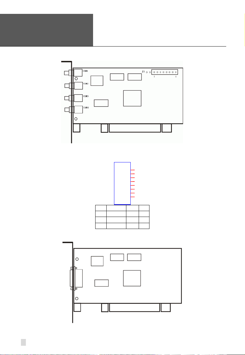
Figure2-4 QSDT4PCRP Video Capture Card
Error! Use the Home tab to apply
标题
1 to the text that you want to
PIN1
VIDEO-1
PIN9
GND
PIN2
GND
PIN10
AUDIO-1
PIN3
VIDEO-2
PIN11
AUDIO-2
PIN4
GND
PIN12
AUDIO-3
PIN5
VIDEO-3
PIN13
AUDIO-4
PIN6
GND
PIN14
NULL
PIN7
VIDEO-4
PIN15
GND
PIN8
GND
SuperDVR & H.264 Series Cards
User Manual
Figure2-5 Definition of Audio and Video Connector’s Pins
appear here. Error! Use the Home
tab to apply 标题 1 to the text that
you want to appear here.
When there are multiple QSDT4PCRP cards connected together, please
connect the lines as in the following figure:
Figure2-6 Multi-Card Connection
13
Error! Use the Home tab to apply
标题
1 to the text that you want to
appear here. Error! Use the Home
tab to apply 标题 1 to the text that
you want to appear here.
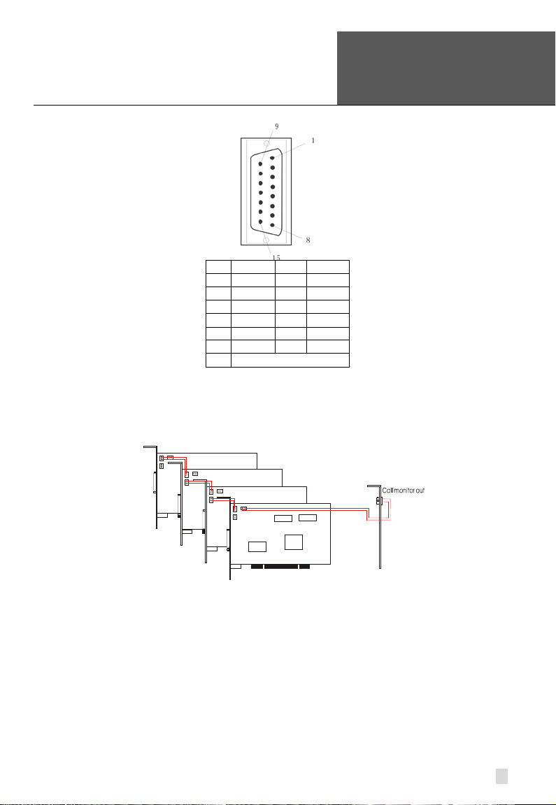
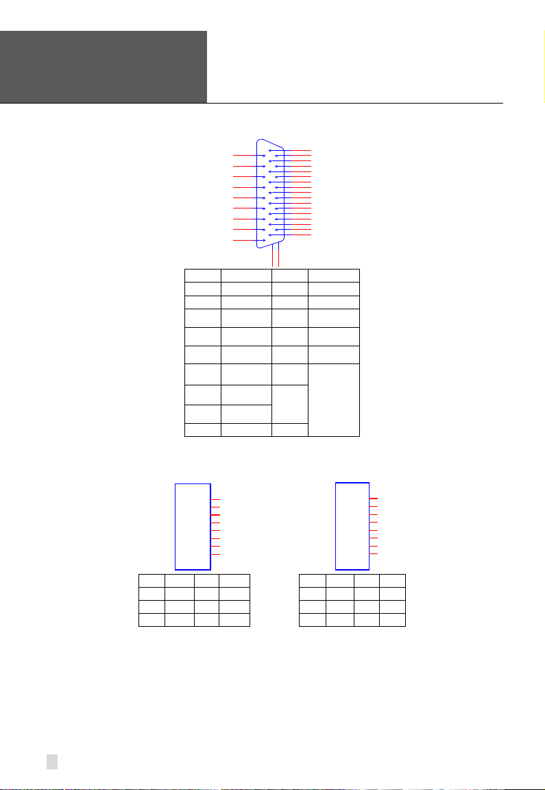
2.1.3 QSDT8PCRP Card Hardware
Figure2-7 QSDT8PCRP Video Capture Card
SuperDVR & H.264 Series Cards
User Manual
Figure2-8 Definition of Audio and Video Connector’s Pins
14
PIN1 VIDEO-1 PIN9 GND
PIN2 GND PIN10 AUDIO-1
PIN3 VIDEO-2 PIN11 AUDIO-2
PIN4 GND PIN12 AUDIO-3
PIN5 VIDEO-3 PIN13 AUDIO-4
PIN6 GND PIN14 NULL
PIN7 VIDEO-4 PIN15 GND
PIN8 GND
Error! Use the Home tab to apply
标题
1 to the text t hat you want to
Data Line
Video Line 9-16
Video Line 1-8
Data Line
Motherboard
Accessorial board
Call Monitor
Audio Line 1-16
SuperDVR & H.264 Series Cards
User Manual
appear here. Error! Use the Home
tab to apply 标题 1 to the text that
you want to appear here.
When there are multiple QSDT8PCRP cards connected together, please
connect the line as in the following figure:
Figure2-9 Multi-Card Connection
2.1.4 QSPD4116 Card Hardware
The Call Monitor interface is used to connect the spot monitor.
Figure2-10 QSPD4116 Video Capture Card
15
Error! Use the Home tab to apply
标题
1 to the text that you want to
P2
DFD202-F -26-R-T
1
2
3
4
5
6
7
8
9
10
11
12
13
14
15
16
17
18
19
20
21
22
23
24
25
26
28
27
PIN1
AUDIO2
PIN11
AUDIO3
PIN2
AUDIO4
PIN12
AUDIO5
PIN3
AUDIO6
PIN13
AUDIO7
PIN5
AUDIO10
PIN15
AUDIO11
PIN6
AUDIO12
PIN16
AUDIO13
/
PIN9
AUDIO16
PIN10
AUDIO1
PIN26
J1
GiL-G-8P-S3T2-E
1
2
3
4
5
6
7
8
J2
GiL-G-8P-S3T2-E
1
2
3
4
5
6
7
8
PIN1
VIN-1
PIN2
GND
PIN1
VIN-5
PIN2
GND
PIN3
VIN-2
PIN4
GND
PIN3
VIN-6
PIN4
GND
PIN5
VIN-3
PIN6
GND
PIN5
VIN-7
PIN6
GND
PIN7
VIN-4
PIN8
GND
PIN7
VIN-8
PIN8
GND
appear here. Error! Use the Home
tab to apply 标题 1 to the text that
you want to appear here.
PIN4 AUDIO8 PIN14 AUDIO9
PIN7 AUDIO14 PIN17
PIN8 AUDIO15
Figure2-11 Audio Connector and Pins Definition
SuperDVR & H.264 Series Cards
User Manual
GND
16
Figure2-12 Video Pins Definition
SuperDVR & H.264 Series Cards
Error! Use the Home tab to apply
标题
NOTICE: Just click ‘Cancel’ and ign ore the pop-up message.
User Manual
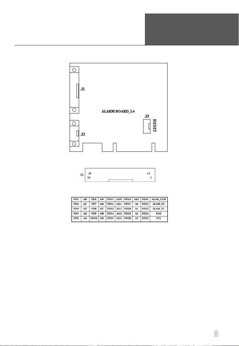
2.1.5 Alarm Board Hardware
1 to the text that you want to
appear here. Error! Use the Home
tab to apply 标题 1 to the text that
you want to appear here.
Connect J2 to PC serial port and you can use alarm board on SuperDVR
system.
2.1.6 Connect Audio Signal
For QSDT4PCRP, connect the audio input device to the microphone
connector on the motherboard.
Before installing the Video Capture Card hardware in PCI port of the
motherboard, make sure you’ve installed Microsoft DirectX 9.0 or later. Then
turn on the computer, the system will display ‘Found new hardware’.
Insert the CD that contains H.264 series capture card driver into the CD tray,
and run Setup.exe program to install the driver. The default installation path is
‘C:\Program Files\SuperDVR’.
Figure2-13 Alarm Board
Figure2-14 Pins Definition of Alarm Board
17
Error! Use the Home tab to apply
标题
1 to the text that you want to
NOTICE: If you get the error message “Can’t find card” when
appear here. Error! Use the Home
tab to apply 标题 1 to the text that
you want to appear here.
SuperDVR & H.264 Series Cards
running the SuperDVR software, try restarting the computer.
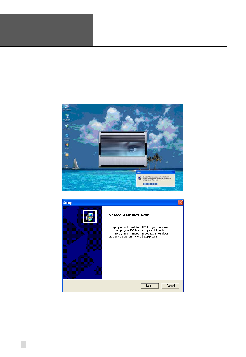
2.2 Install Video Capture Card Driver
STEP1: Run Setup.exe, and the installation interface appears as shown
below:
User Manual
Figure2-15 H.264 Series Video Capture Card Installation Interface
Figure2-16 Welcome Page
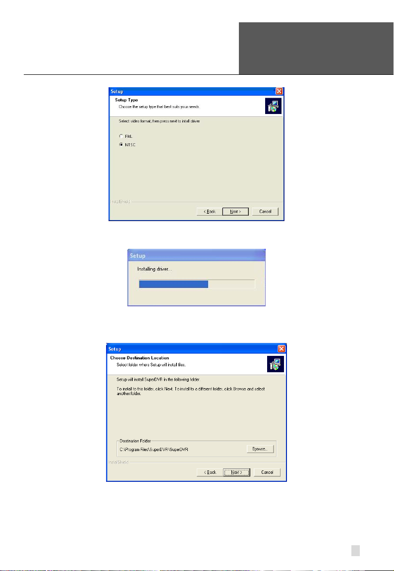
STEP2: Select video system, in the US we use NTSC format, click “next”
18
SuperDVR & H.264 Series Cards
Error! Use the Home tab to apply
标题
User Manual
1 to the text that you want to
appear here. Error! Use the Home
tab to apply 标题 1 to the text that
you want to appear here.
STEP3: Install driver fir st.
STEP4: After this process, it begins to install the application package
SuperDVR, as shown below:
Figure2-17 Select Video Format
Figure2-18 Rate of Progress of Driver Installation
Figure2-19 Select Installation Folder
19

Error! Use the Home tab to apply
标题
1 to the text that you want to
NOTICE: When you install the driver software on Microsoft VISTA
system, you need select the option shown below. Other steps of
appear here. Error! Use the Home
tab to apply 标题 1 to the text that
you want to appear here.
SuperDVR & H.264 Series Cards
STEP5: Select a folder or use the default SuperDVR, and click ‘Next’.
User Manual
Figure2-20 Selecting program folder
STEP6: Click ‘Next’.
Figure2-21 Driver and Application Installation Finished
STEP7: Click ‘Finish’.
STEP8: After all the processes are finished, it will create a shortcut on the
desktop. Restart the computer and launch the surveillance program.
20
Figure2-22 Shortcut of SuperDVR

SuperDVR & H.264 Series Cards
Error! Use the Home tab to apply
标题
installing the driver software on Microsoft VISTA sys te ms are the
User Manual
same as on Microsoft XP systems.
1 to the text that you want to
appear here. Error! Use the Home
tab to apply 标题 1 to the text that
you want to appear here.
Figure2-23 Installing the Software on VISTA
In cases where users cannot run the SuperDVR program, restart the
computer.
You also need to disable the new user access control function in Vista. To do
so:
Click on the Start button.
Click on Control Panel
Click on User Accounts
Click on the option to “Turn user account control on or off”
Click on the check mark in the box in front of “Use user account control to
help protect your computer” to remove it.
Click on OK.
21

Error! Use the Home tab to apply
标题
1 to the text that you want to
NOTICE: Users can tell which buttons are working by the color of
appear here. Error! Use the Home
tab to apply 标题 1 to the text that
you want to appear here.
SuperDVR & H.264 Series Cards
3 Main Display Interface
Run the SuperDVR program and the main display appears as shown below:
User Manual
Figure3-1 SuperDVR Mai n Display Interface
3.1 Display Control Panel
3.1.1 Display Control Panel
Figure3-2 Display Control Panel
Display control pane l includ es Displ ay M ode buttons, disk free space indicator,
and ‘Auto Dwell’ button. Every button has its built-i n in di cator light. When you
switch the buttons on and off, the relative indicator lights turn on and off to
indicate the working status.
the buttons.
3.1.2 Display Modes
Figure3-3 Display Modes Panel
3.1.3 Flip Pages
When the display mode is 1CH, 4CH, 9CH, 16CH, click
display the next window according to the display mode.
22
, system will

SuperDVR & H.264 Series Cards
Error! Use the Home tab to apply
标题
User Manual
3.1.4 Auto Dwell Display Mode
1 to the text that you want to
appear here. Error! Use the Home
tab to apply 标题 1 to the text that
you want to appear here.
If users want to see all the channels in sequence, then click
to enter
Auto Dwell display mode.
3.1.5 Capture
If users want to capture a picture from the screen they can click
, the
system will save 32 pictures to the default folder on the disk, c: \ path.
3.1.6 Urgent Record
Click
, system will be record and save all the cameras.
3.2 Login
Click , and the login window appears. Input the user name and password,
the default user name is ‘SYSTEM’ with no password, users will then access
the main interface. Users can change password for SYSTEM and create new
user names and passwords once they have entered the system.
Figure3-4 Main Interface
23

Error! Use the Home tab to apply
标题
1 to the text that you want to
appear here. Error! Use the Home
tab to apply 标题 1 to the text that
you want to appear here.
SuperDVR & H.264 Series Cards
3.3 Record
3.3.1 Record Modes
According to different record triggering methods, video capture cards offer
users 4 different record modes:
• Schedule record mode (timer)
• Manual record mode
• Motion Detection record mode
• Sensor Alarm record mode
Motion Detection record mode and Sensor Alarm record mode are called
Alarm Record.
If users use multiple cameras to record, every camera works separately and
the recorded files are also saved separately. The parameters, i.e. camera ID,
record date/time, and record mode are all saved together with the recorded
file.
3.3.2 Record Setup
User Manual
In the ‘Record Panel’ of the Basic Configuration page, users can set all the
necessary parameters for recording.
1. Time Stamp
By selecting this option, the record date / time message appears in the
recorded file images.
2. Switch
By selecting this option, users can turn on corresponding cameras. If there is
no camera on a channel, do not select this option and you will save system
resources.
3. Manual Record
By selecting this option, the images from the sele cted ca mera will be recorded
and saved all the time (24 hour recording).
24
Figure3-5 Record Configuration Panel

Error! Use the Home tab to apply
标题
1 to the text that you want to
NOTICE: Users can select more than one record mode.
SuperDVR & H.264 Series Cards
User Manual
appear here. Error! Use the Home
tab to apply 标题 1 to the text that
you want to appear here.
4. Manual Recording Frame Rate
Select the recording frame rate for manual record mode.
5. Schedule Record
This option allows you to record on a set schedule.
6. Schedule Record Frame Rate
Select Schedule Recording frame rate.
7. Motion Detection
By selecting this option, users can set the selected channels to record when
motion is detected in front of the camera.
8. Motion Record Frame Rate
Select recording frame rate for Motion Detection record mode.
9. Sensor Record Frame Rate
If sensors are utilized to trigger recording, users can select recording frame
rate here.
10. Camera Security
Users are divided into t hree types: N orma l user, Power user and Adminis trator.
By selecting this option, only administrators can see the selected channels.
11. Record Quality
Select recording image quality here.
12. Audio in
SuperDVR 6.0 can support one channel of microphone audio input signal on
the PC motherboard and any audio inputs that are on the card if any. Users
can choose one video channel for each available audio input.
3.3.3 Record Status Panel
Figure3-6 Record Status Panel & Alarm Output Stat u s Panel
Meanings of indicator light colors in row one are shown below:
•
•
•
•
Grey light: Normal State
Light Green light: Manual Record State
Dark Green light: Schedule Record State
Yellow light: Motion Detection Record State
25

Error! Use the Home tab to apply
标题
1 to the text that you want to
NOTICE: You can select a high frame rate for a short time manual
NOTICE: Users need to setup parameters in three places to enable
channels in ‘Basic
Configuration’.
appear here. Error! Use the Home
tab to apply 标题 1 to the text that
you want to appear here.
• Red light: Sensor Alarm Record State
SuperDVR & H.264 Series Cards
User Manual
•
When the indicator light color turns into red
Blue light: Video Loss State
in row two, it means there is
an alarm output.
3.3.4 Manual Record Mode
Manual Record mode is the most commonly used recording mode. If a
special event occurs, users can select this recording mode and record
immediately.
recording, while selecting a low frame rate for long time Scheduled
Record.
3.3.5 Sensor Alarm Record Mode
Users can use sensor s to trig ger sensor alarm recording on r elative ch annels.
At that time, the record status indicator light will turn red
.
3.3.6 Motion Detection Record Mode
This will enable the system to detect image changes and begin to record by
activating motion detection and motion alarm recording. For instance,
somebody opens the door, and the system detects image changes from the
camera and begins to record, then users can play back the recorded file and
find out who opened the door. When there is no movement, the system will
not record which saves system resources, and makes it easier to find
recorded events. The indicator light color in the record status panel will be
yellow
.
motion detection recording.
• Select ‘Motion Detection’ for desired
Configuration’.
• Configure the motion detection areas for desired channels in
‘Motion Detection Configuration’.
• Configure working schedule for desired channels in ‘Schedule
26

Error! Use the Home tab to apply
标题
1 to the text that you want to
SuperDVR & H.264 Series Cards
User Manual
appear here. Error! Use the Home
tab to apply 标题 1 to the text that
you want to appear here.
3.3.7 Schedule Recording
Users can set working schedule for all of the recording modes in ‘Schedule
Configuration’. The dark green light
in reco rd status panel sho ws the
corresponding channel is in Schedule Record mode. Users can change
record mode to manual record at any time, and the dark green light
change into a light green light
.
will
Please refer to ‘4.4 Schedule Configuration’ for details.
3.3.8 Recycling Recordings
If users enable the Recycling Record function and all the selected HDD
partitions are full, the oldest recorded data will be overwritten by the latest
recorded data.
Users can set recording storage sequence for HDD partitions. The recording
storage will automatically jump to the next partition when the current one is
full. If all the partitions are full and recycling record mode has been enabled,
the new data will overwrite the oldest recorded data automatically. Users can
also set a HDD minimum storage alarm. Then once the present storage
space is l ess than the minimum stor age needed, a nd recyclin g record mo de
has not been enabled, the recording will automatically stop.
27

Error! Use the Home tab to apply
标题
1 to the text that you want to
Basic Configuration
Schedule configuration
Video configuration
Motion Detection Configuration
Alarm Configuration
P.T.Z Configuration
User Configuration
Save and Return
appear here. Error! Use the Home
tab to apply 标题 1 to the text that
you want to appear here.
Click to enter the main setup interface.
SuperDVR & H.264 Series Cards
User Manual
4 System Setup
The definitions of the buttons in Figure4-1 are shown below:
4.1 Basic Configuration
Click to enter the basic configuration page where users can setup the
system, or just use the defaults.
28
Figure4-1 Basic Confi gura ti on

SuperDVR & H.264 Series Cards
Error! Use the Home tab to apply
标题
User Manual
1 to the text that you want to
appear here. Error! Use the Home
tab to apply 标题 1 to the text that
you want to appear here.
Figure4-2 Caption and Gener al Confi guration
1. Dwell Interval.
If users enable Auto Dwell function on the main interface page, users can set
the dwell time, in seconds, of a screen here.
2. Caption
There are four options, None, ID, Name, and ID/Name for users to select for
all the channels.
• ‘None’ means no title or name;
• ‘ID’ means camera numbers, i.e. 1, 2, 3 and so on;
• ‘Name’ means camera names, i.e. Cam1, Cam2 and so on;
• ‘ID/Name’ means both camera number and camera name, i.e. 1/Cam1,
2/Cam2 and so on.
3. Resolution
There is one resolution option, 320× 244 for users to select for all the
channels.
4. Call Monitor
Users can connect another monitor to the card and select the display modes
here.
The following area is f or y our recording data st or age area. Please see section
3.3.8.
SuperDVR shows all the available HDD partitions for users. Users can select
one or more of the partitions that will be used in sequence from top to bottom.
Please refer to section 3.3.8 to learn more about recycling records.
Figure4-3 Record Data Storage Precept
29

Error! Use the Home tab to apply
标题
1 to the text that you want to
appear here. Error! Use the Home
tab to apply 标题 1 to the text that
you want to appear here.
SuperDVR & H.264 Series Cards
In the following area in the basic configuration page, users can input the
computer user name and password in the relative boxes. Then when
restarting the computer system, it will give access to the system with the user
name and password that was put in the boxes.
User Manual
Figure4-4 Computer System Reboot Setup
Since the windows system may become unstable after a couple of days of
continuous operating, it may cause SuperDVR to become unstable. You can
use the software support auto-reboot option to help avoid this. Select
and set the interval by day, which will guide the system to
reboot automatically according to t he setup.
5. Capture browse
This item is the save path for captured files
Users can fill in the specific s av e path for their captured pictures.
Click
to return to the main display interface.
4.2 Video Configuration
Click and enter the video configura tion p a ge as shown below. Users c an
change the values of corresponding items, i.e. contrast, brightness, hue,
saturation, auto gain, by moving the levers on the bar s. C l ic k ‘ Default’, and all
the values will return to the default value.
30

SuperDVR & H.264 Series Cards
Error! Use the Home tab to apply
标题
User Manual
1 to the text that you want to
appear here. Error! Use the Home
tab to apply 标题 1 to the text that
you want to appear here.
Definitions of the setup items:
1. Contrast
Set image color contrast.
2. Brightness
Set image brightness.
3. Hue
Set image hue.
4. Saturation
Set image Saturation
5. Default
Load defaults, i.e . reset the value of th e first four items. The range of values is
from 0—255.
4.3 Motion Detection Configuration
Click and enter the Motion Detection Configuration page,
Figure4-5 Video Configuration
31

Error! Use the Home tab to apply
标题
1 to the text that you want to
appear here. Error! Use the Home
tab to apply 标题 1 to the text that
you want to appear here.
SuperDVR & H.264 Series Cards
User Manual
Figure4-6 Motion Detect ion Configuration
Definition of the setup items:
1. Sensitivity
Users can set motion detection sensitivity here.
2. Speed
Motion detection speed
3. Block Number
Set grid’s number.
4. Defaults
Reset to default settings.
5. Select All
Select the entire area of the channel as detection sensitive
6. Clear
Clear all the detection areas and then you can select a customized detection
area using the cursor.
4.3.2 Set Motion Detection Area
If users want to customize the detection area for a certain channel, first select
the camera, then select ‘Clear’ and drag the cursor in the box in the left side.
You will see a green box appear which shows the motion detection area. You
can select a maximum of 16 customized areas for each channel.
4.3.3 Clear Motion Detection Area
By clicking ‘Clear’, you can clear all the selected areas.
32

Error! Use the Home tab to apply
标题
1 to the text that you want to
NOTICE: The added schedule should not be duplicate of the former
SuperDVR & H.264 Series Cards
User Manual
appear here. Error! Use the Home
tab to apply 标题 1 to the text that
4.4 Schedule Configuration
Click to enter the Schedule Configuration page as shown below:
you want to appear here.
Figure4-7 Schedule Configuration
Our H.264 series cards have powerful schedule configuration options. Every
channel has three kinds of recording modes, i.e. schedule record, motion
detection record and sensor alarm record. You are able to set schedules from
Sunday to Monday separately for all of the three recording m odes. Sensor
alarm recording mode has the highest priority among all recording modes.
Here users can set schedules for all modes.
When users need to edit the schedule for a channel, first select the camera
name in the three record mode groups, and select the color bars on the right
side, then select ‘Edit’ to edit schedules. Click ‘Add’ to add schedule for a
certain channel.
settings.
Click ‘Delete’ to delete schedule. Click ‘Clear All’ to delete all the schedules
for a certain channel.
See the Figure 4-8 Edit Schedule to see the edit schedule window for a
channel:
33

Error! Use the Home tab to apply
标题
1 to the text that you want to
appear here. Error! Use the Home
tab to apply 标题 1 to the text that
you want to appear here.
SuperDVR & H.264 Series Cards
User Manual
Figure4-8 Edit Schedule
4.5 Motion Detection Alarm Configuration
4.5.1 Alarm Triggering Conditions Configuration
The system can receive alarms from both local place and network.
Local Alarm Record Triggering Configuration
Figure4-9 Local Alarm Triggering Configuration
Explanation of options:
1. Buzzer
Users can select whether to trigger the computer buzzer if alarms have been
triggered and also select how long the buzzer sounds.
2. Pre-Alarm Record
Users can select whether to enable alarm pre-record and also pre-record
time.
3. Big Screen Holding Time
The corresponding channel will be full screen when an alarm is triggered. Set
the full screen hold time here.
4. Motion Holding Time
How long the recording continues after motion stops.
5. Sensor Holding Time
How long the recording continues after sensor stops.
6. Disk Shortage Alarm
If the Partition free spa ce is less than the set percent, it will stop record ing or
recycling, but give alarm tips according to the settings.
34

SuperDVR & H.264 Series Cards
Error! Use the Home tab to apply
标题
User Manual
4.5.2 Alarm Record
1 to the text that you want to
appear here. Error! Use the Home
tab to apply 标题 1 to the text that
you want to appear here.
Every sensor can trigger multiple channels to record. For example, if users
select CAM1, CAM4 and CAM5 for Sensor2, then once the sensor is
activated, CAM1, CAM 4 and CAM5 will begin to recor d. U s er s ca n a lso se lec t
the voltage, high and low, for alarm signals.
4.5.3 Alarm Output
Press in the main interface to access the following Alarm Configuration
area where users can setup a motion detection alarm, sensor alarm, and
Figure4-10 Alarm Trigger Method Configuration
Figure4-11 Alarm Output Configuration
35

Error! Use the Home tab to apply
标题
1 to the text that you want to
NOTICE: You should choose our addit ional alarm device board while
appear here. Error! Use the Home
tab to apply 标题 1 to the text that
you want to appear here.
SuperDVR & H.264 Series Cards
HDD space shortage alarm.
1. Video Loss
Users can select alarm output for this option. For example, users select
alarm_out1 and alarm_ out3 for video loss . T hen v ideo loss of any channel will
trigger alarm_out1, alarm_out3 to show a red light in the Alarm output status
panel (refer to Figure3-6 for reference to this panel).
2. Disk Alarm
When HDD available space is less than the set value (see Figure4-9), it will
trigger alarm.
3. Sensor
Sensor 1: If users have mounted sensors, when the sensors have been
activated, it will trigger the selected output alarms.
Sensor 2 - Sensor 16: Two QSPD4116 cards have a maximum of 16 sensor s.
4. Motion
Motion 1: Users can set the output of motion detection alarm by different
alarms and remote alarm.
Motion 2 - Motion 16: 32CH card has maximum 16 motion alarms.
using two QSPD4116 cards for alarm I/O.
4.5.4 Auto Mail Function
Users can select the above-mentioned alarms to be output by Auto Mail.
NOTICE: Before you setup this function, make sure the DVR is set to
Motion Recording.
Click ‘Auto Mail’ icon on the left top side of alarm configuration page to enter
the following area to make Auto Mail setup, refer to Figure4-12.
User Manual
36

SuperDVR & H.264 Series Cards
Error! Use the Home tab to apply
标题
Receiver's E-mail Address
Sender's SMTP
Sender's E-mail Address
Sender's User Name
Sender's Password
E-mail Subject
User Manual
1 to the text that you want to
appear here. Error! Use the Home
tab to apply 标题 1 to the text that
you want to appear here.
In this area, users can set receiver and sender’s E-mail SMTP server and
address. Note: the address of receiver and sender can be th e same.
To test the settings, click ‘Send Mail Test’. If all settings are okay, response
‘Message Sent Successfully’ will pop up. If some settings are wrong, a
warning message will pop up.
Enable ‘Attachment’, then a picture of what triggered the alarm will be sent to
the selected mailbox, refer to Figure4-14.
Figure4-12 Auto Mail Setup Interface
Figure4-13 Auto Mail Setup
37

Error! Use the Home tab to apply
标题
1 to the text that you want to
NOTICE: For every alarm event, only one picture will be sent.
appear here. Error! Use the Home
tab to apply 标题 1 to the text that
you want to appear here.
SuperDVR & H.264 Series Cards
User Manual
Figure4-14 Attachment Setup
4.6 E-map Configuration
E-map is used to show full geographic range covered by the whole monitoring
system in the form of map. An E-map features simple operation and direct
display of status and is generally graded or tiered in the form of a tree
diagram.
4.6.1 Edit Map
The system only supports bmp or jpg image format.
NOTICE: Y ou need to draw the floor plan of where you want to install the
cameras in a program such as Paint or Photoshop and save it in BMP
format before using this feature.
Click to enter ‘Emap → Emap Edit’, press right key of Load Picture in
the default interface of the map and select the required map file in the related
folder, open the file and the map will be displayed in this interface, as shown
in Figure4-15 E-Map Edit.
38

SuperDVR & H.264 Series Cards
Error! Use the Home tab to apply
标题
User Manual
1 to the text that you want to
appear here. Error! Use the Home
tab to apply 标题 1 to the text that
you want to appear here.
Figure4-15 E-Map Edit
Drag the icon of a camera to the corresponding position on the map, a
maximum of 32 ca meras can be set simultaneously, Click ‘change icon’ of
camera by right key to change icon and click ‘Delete’ to cancel camera. After
editing, click right key in the map and select ‘Save Map’ to save t he current
map.
A gray map icon can be drawn to the corr esponding pos ition in the map on the
right and set it as a sub-map of the current map, or click the gray map icon on
the left by right key and select ‘Open’ to build a new map. You can also click
the blue map icon on the left by right key, and select ‘Rename’ to change the
name of the map or select ‘Close’ to cancel this map.
4.6.2 View Map
Click
to enter E-map, where the user can view distribution of all
cameras in the map, as in Figure4-16 View Cameras.
39

Error! Use the Home tab to apply
标题
1 to the text that you want to
NOTICE:
1. The map tree currently supports three levels and it is invalid for
it will be enlarged and
shortened proportionally and standard size of picture frame is
user can invite an engineering merchant to make the practical map
or draw a map by their own according to their actual needs, then
appear here. Error! Use the Home
tab to apply 标题 1 to the text that
you want to appear here.
SuperDVR & H.264 Series Cards
User Manual
Figure4-16 View Cameras
When a channel alarm is tri ggered , the camera icon will flash a yellow alarm
signal. Select ‘Auto Show’, in case of an accidental alarm, an alarming
screen will pop out automatically and you can know about the alarming
position immediately. Click the camera head by right key to show the screen
on the spot.
any more then that.
2. For loading of a picture, when any side of length and width of the
picture exceeds size of picture frame,
833x678.
3. On this interface, click camera by right key to display the spot and
the 3316 card does not support this function temporarily.
4. If ‘Auto Show’ is set in case that E-map pops up by automatic
alarming, the E-map interface set with ‘Holding Time’ without any
operation and alarm will be close automatically. ‘Auto Show’ is
invalid when the E-map is opened manually.
5. The map in the E-map is the default demonstration map, and the
scan and save it in the computer to picture.
40

SuperDVR & H.264 Series Cards
Error! Use the Home tab to apply
标题
User Manual
4.7 P.T.Z Control Configuration
Click and enter PTZ Configuration:
1 to the text that you want to
appear here. Error! Use the Home
tab to apply 标题 1 to the text that
you want to appear here.
4.7.1 Protocol Setup
Users can select different prot ocol s, serial port number for P.T.Z devices.
The settings you enter here must match the setting on the PTZ camera.
1. Port
Users can set serial port number.
2. Protocol
Communication protocol of P.T.Z device
SuperDVR supports the following protocols:
Figure4-17 PTZ Configuration Panel
Figure4-18 P.T.Z Protocol Setup
41

Error! Use the Home tab to apply
标题
1 to the text t hat you want to
NOTICE: Users should look at the control board of the P.T.Z device
appear here. Error! Use the Home
tab to apply 标题 1 to the text that
you want to appear here.
SuperDVR & H.264 Series Cards
DSCP, DH-SD, Lilian, Minking, Neon, PelcoD, PelcoP, Star, VIDO, VISCA
3. Address
Communication address of P.T.Z device (ID number)
4.7.2 Serial Ports Setup
Users should first enable the P.T.Z control function of a certain camera and
select a port number in P.T.Z Protocol Setup (refer to Figure4-18), and then
set corresponding parameters in the area below:
User Manual
Figure4-19 P.T.Z Serial Port Setup
1. Port
Users can set port number.
2. Baud Rate
Set P.T .Z dev ice Baud Rat e to match setting on camera, default value is 9600.
3. Data Bits
Default value is 8.
4. Parity
Odd and even parity bit, default None.
5. Stop Bits
Default value is 1.
and get the Baud Rate, Protocol, and Address first, then enter the
same values into the SuperDVR program.
42

SuperDVR & H.264 Series Cards
Error! Use the Home tab to apply
标题
User Manual
4.8 Users Configuration
Click to access the User’s Configuration area:
1 to the text that you want to
appear here. Error! Use the Home
tab to apply 标题 1 to the text that
you want to appear here.
After installing the SuperDVR program, it will automatically create an
administrator user with the user name SYSTEM with no password. Users can
use this username to log in the system and ‘Add’, ‘Edit’ or ‘Delete’ us ers’
parameters.
4.8.1 Change User rights
Select a user in User Configuration area (refer to Figure4-20), and click ‘Edit’
to entire Edit User ar ea, as shown below:
Users can edit user’s password and rights here, but not the user name.
The system offers three kinds of rights:
Figure4-20 User confi gura ti on
Figure4-21 User Password and Rights Edit
43

Error! Use the Home tab to apply
标题
1 to the text that you want to
NOTICE: Administrators can change and authorize rights to Power
appear here. Error! Use the Home
tab to apply 标题 1 to the text that
you want to appear here.
SuperDVR & H.264 Series Cards
• Administrator: this user has the right to change all the settings and
playback. This user also has the right to assign users power user rights and
normal user rights.
• Power User: This type of user is authorized by the administrator. The
administrator assigns rights to power users by checking boxes in the Power
User list. Please refer to the following figure:
User Manual
•
Normal User: Normal user’s rights are also assigned by the administrator.
They have the same list of av ailabl e right s as Power Users. However, whether
they can possess a right is be decided by the administrator. Only if the
administrator assigns that right, will they have the right. For example, if Basic
Configuration is checked, the Normal User can access these functions.
Users and Normal Users, but they cannot change or authorize other
Administrators’ rights.
4.8.2 Add User
Click ‘Add’ in User Configuration (refer to Figure4-20), to access the Add
User area:
Figure4-22 Add User
Input user name, password, confirm password and select user rights, and
then click ‘OK’.
4.8.3 Delete User
Select the user name in User Configuration (refer to Figure4-20), and click
‘Delete’, and confirm delete. See below:
44

SuperDVR & H.264 Series Cards
Error! Use the Home tab to apply
标题
User Manual
1 to the text that you want to
appear here. Error! Use the Home
tab to apply 标题 1 to the text that
you want to appear here.
Figure4-23 Confirm Delete User
45

Error! Use the Home tab to apply
标题
1 to the text t hat you want to
appear here. Error! Use the Home
tab to apply 标题 1 to the text that
you want to appear here.
SuperDVR & H.264 Series Cards
5 P.T.Z Control
Click in the SuperDVR main display interface (refer to Figure3-1) to
access the P.T.Z control area:
User Manual
Users can control P.T.Z. devices by the function buttons on the right side,
shown below:
In the lower circ le, th er e ar e f ive functio n butt ons, i.e. up, down, left, right, and
stop. The other buttons are Focus buttons (+ and -), Zoom buttons (+ and -),
and Iris buttons (+ and -). Click
corresponding values.
When users need to use P.T.Z control, first enter P.T.Z Control Interface (refer
to Figure5-1), and click the corresponding channel (users will see a red fringe
around the channel), then users can begin to control the enabled P.T.Z.
46
Figure5-1 P.T.Z Control Interface
Figure5-2 P.T.Z. Control Function Buttons Panel
and to incr ease and decr ease the

Error! Use the Home tab to apply
标题
1 to the text that you want to
NOTICE: After pressing left mouse button on any function button in
SuperDVR & H.264 Series Cards
User Manual
appear here. Error! Use the Home
tab to apply 标题 1 to the text that
you want to appear here.
camera.
P.T.Z Control Function Panel (refer to Figure5-2), PTZ camera starts
moving, when user releases it, PTZ camera stops moving.
Figure5-3 Speed Adjustment
Users can select different Pan Speeds, Tilt Speeds, Focus Speeds and Zoom
Speeds for P.T.Z. devices.
1. Pan Speed
Set horizontal rotating speed.
2. Tilt Speed
Set vertical rotating speed.
3. Focus Speed
Set camera focus speed.
4. Zoom Speed
Set zoom in/ zoom out speed.
Click
and a pop-up window will appear; users can choose different
presets or group sets.
47

Error! Use the Home tab to apply
标题
1 to the text that you want to
appear here. Error! Use the Home
tab to apply 标题 1 to the text that
you want to appear here.
Figure5-4 Preset and Group Select
SuperDVR & H.264 Series Cards
Click to set Preset point and change Preset point name. Every
Group includes multiple Preset points. If users select preset1, preset2 and
preset3 for group1, preset1, preset2 and preset3 will be automatically
accessed in sequence after users select group1 for auto scout.
User Manual
Click , the following pop-up window will appear:
Dwell: users can set the dwell time of a preset here.
Figure5-5 Preset
Figure5-6 Group Configuration
48

Error! Use the Home tab to apply
标题
1 to the text that you want to
SuperDVR & H.264 Series Cards
User Manual
appear here. Error! Use the Home
tab to apply 标题 1 to the text that
you want to appear here.
6 Record Search & Playing Back
Click in the SuperDVR Main Display Interface (refer to Figure3-1) and
access the following areas:
This interface is divided into 4 par ts , record search area, reco rd playba ck area,
record play area, and other functions area.
Press and return to the live surveillance status.
Figure6-1 Search and Playback Interface
49

Error! Use the Home tab to apply
标题
1 to the text that you want to
appear here. Error! Use the Home
tab to apply 标题 1 to the text that
you want to appear here.
SuperDVR & H.264 Series Cards
6.1 Record Search
A, B and C marks the areas of the three search met hods.
• A: Search by date
• B: Search in backup file and original file
• C: Search by recording mode. This is useful when user wants to look
through some important events.
Users can select one or more of the above three searchi ng methods to search
for needed recorded files.
Figure6-2 Record Search Area
User Manual
6.2 Playing Back and Control
50
Figure6-3 Playing Back and Control

SuperDVR & H.264 Series Cards
Error! Use the Home tab to apply
标题
User Manual
Explaination of the button functions:
• : Play / Pause
1 to the text that you want to
appear here. Error! Use the Home
tab to apply 标题 1 to the text that
you want to appear here.
•
: Stop
• : Reverse. This button is valid when playing back by single channel
• : Previous Section. This button is valid when playing back by single
channel
•
: Next Section. This button is valid when playing back by single
channel
•
: Previous Frame. This button is valid when playing back by single
channel playing back in pause mode
• : Next Frame. This button is valid when playing back by single
channel playing back in pause mode
Users can select suitable playing speed in the area as shown below:
The following area shows the recorded files of different channels:
The upper bar shows the hours in a wh ole day. Click the bar, and it will be
magnified 10 times, therefore users can see the detailed time marks. When
searching for a certain section of the file, users can draw the scrolling-bar to
the area that most likely contains the needed section. If necessary, click the
bar once and see the magnified time marks for precise search.
The left side shows the available channels. When a certain chan nel has bee n
selected for playing back, the background color will be highlighted, or it’s dark
gray, and a tick sign will appear beside the channel title.
The main area at the ce nter gi v es details of the recorded files. Different colors
of the bar show the different types of record modes of the files. The following
Figure6-4 Playing Speed Controller
Figure6-5 Recorded Files Br owse r
51

Error! Use the Home tab to apply
标题
1 to the text that you want to
appear here. Error! Use the Home
tab to apply 标题 1 to the text that
you want to appear here.
are the definitions of the color bars:
Blue: Manual Record Events
•
•
Green: Schedule Record Events
•
Yellow: Motion Detection Record Events
•
Red: Sensor Alarm Record Events
SuperDVR & H.264 Series Cards
User Manual
Click
to play selected recorded files. The system offers play back in
1 Ch, 4CH, 9 CH, and 16CH. The following is the multiple channel playback
options in the control area:
Figure6-6 Multiple Channe l Pl a ybac k Contr ol
The system default playiback mode is one channel. That is Camera1. If users
need to change to other channels, then click
and the channel
configuration window will appear, as shown below:
Figure6-7 Channel Configuration Dialog for Single Channel Playback Mode
Users can select o ne cha nne l f r om all th e available channels f or pl ay ing ba ck .
In case user needs to playback 4 channels at the same time, then click ,
and the following channel configuration window will appear:
Figure6-8 Channel Configuration Dialog for 4-channel Playback Mode
Users can select any four channels from all the available channels for playing
back.
The system offers quick select methods for users. For example, by selecting
52

Error! Use the Home tab to apply
标题
1 to the text that you want to
TIP
SuperDVR & H.264 Series Cards
User Manual
appear here. Error! Use the Home
tab to apply 标题 1 to the text that
you want to appear here.
‘Third 4 Channels’ , Camera9, Camera10, Camera11, and Camera12 will be
quickly be selected simultaneously.
If user needs to playback 9 channels at the same time, then click
, and
the following channel configuration window will appear:
Figure6-9 Channel Configuration Dialog for 9-channel Playback Mode
Users can select any 9 channels from all the available channels for playing
back. Users can also use the quick select methods in the system.
If user needs to pl aybac k 16 channe ls at the same t ime, then click
, and
the following channel configuration window will appear:
Figure6-10 Channel Configuration Dialog for 16-channel Playing Back Mode
Then click ‘OK’ to play back.
Click any channel and magnify it to see the single channel. Click again to return to the
former playback mode.
6.3 Other Functions
6.3.1 Recorded File Backup
Click
and enter the following menu:
53

Error! Use the Home tab to apply
标题
1 to the text that you want to
appear here. Error! Use the Home
tab to apply 标题 1 to the text that
you want to appear here.
SuperDVR & H.264 Series Cards
User Manual
Figure6-11 Recorded Files Backup
Users can select corresponding cameras and copy the recorded files to
another path in this area. This is the file backup function of the system.
The interface is divided into four areas:
• A: Camera Selection Area
• B: Time and Date Selection Area
• C: Operation Area
• D: Information Area
In A area, users can select one or more camer a s.
In B area, users can set start time/date and end time/date, and then backup
the files recorded by channels selected in A area by the time interval.
In C area, users can set backup path.
Click ‘Start’ to backup files.
6.3.2 Delete Recorded Files
Click
and the following window will appear:
Users first select the channel on the left side, and then select start time/date
and end time/date of the recorded files, click ‘Start’ to delete files.
54
Figure6-12 Delete Recorded Files

SuperDVR & H.264 Series Cards
Error! Use the Home tab to apply
标题
User Manual
6.3.3 Capture Pictures
The definitions of the function buttons are shown below:
: Capture picture
: Print setup
: Print captured picture
1 to the text that you want to
appear here. Error! Use the Home
tab to apply 标题 1 to the text that
you want to appear here.
NOTICE: This
single channel
function is valid only in playback pause mode of
.
When in single channel playback pause mode, the following color control
panel (Figure6-13) will automatically appear, which can be used to make
picture quality adjustments for the present channel, including brightness,
contrast, saturation and hue, and press ‘Default’ to restore the original
settings.
Figure6-13 Color Control Panel
When in the single channel playback pause mode, click and the
following window will appear:
Figure6-14 Capture Multiple Images in Sequence
55

Error! Use the Home tab to apply
标题
1 to the text that you want to
appear here. Error! Use the Home
tab to apply 标题 1 to the text that
you want to appear here.
SuperDVR & H.264 Series Cards
Select path and click ‘Save’ to save the picture. User can also print the
images that have been captured.
User Manual
Click
By clicking
and display print setup as shown below:
Figure6-15 Print Setup
users can display print preview as shown below:
Select and then click or to move the picture up, down,
left and right. Select
out on the image. Press
‘Print’ in the print preview window to print the image directly.
56
Figure6-16 Print Preview
and then click and to zoom in and
to return to the original settings. Press

Error! Use the Home tab to apply
标题
1 to the text that you want to
SuperDVR & H.264 Series Cards
User Manual
appear here. Error! Use the Home
tab to apply 标题 1 to the text that
you want to appear here.
6.3.4 Image Zoom in/out
When in sin gle channel playback mode, the zoom control icons
will appear. Select and click on the channel, it will zoom out the image.
By clicking continuously, the image will be zoomed out continuously. Select
and do the some operation to get the opposite effect. Click and
recover the original size. Take the following three pictures for ex ample.
Figure6-17 Example: original size
Figure6-18 Example: zoomed out
57

Error! Use the Home tab to apply
标题
1 to the text that you want to
appear here. Error! Use the Home
tab to apply 标题 1 to the text that
you want to appear here.
SuperDVR & H.264 Series Cards
User Manual
Figure6-19 Example: zoomed in
58

Error! Use the Home tab to apply
标题
1 to the text that you want to
SuperDVR & H.264 Series Cards
User Manual
appear here. Error! Use the Home
tab to apply 标题 1 to the text that
you want to appear here.
7 Remote Surveillance & Playback
Remote Live Surveillance
Surveillance system supports Remote Surveillance through LAN, Internet,
and Intranet. Simply enable the Webcam function of the system on a
computer which is connecte d to the Internet, and the computer system will
become an Internet Webcam server. On any other computer that connects to
Internet, input the public IP server address in IE browser (see 7.2.1 Finding
Router’s Public IP Address), the end users can get high quality real time
image from the server (depending on available bandwidth) and als o control
the P.T.Z devices.
7.1 Remote Surveillance Server Configuration
Users should first enable the Web Camera Services in Basic Configuration
(refer to Fig 7.1) and set other settings as shown below:
HTTP Port
Web service & download service port, default value is 80.
Data Port
Data transmission port, default value is 1159.
Command Port
Control command port, default value is 1160.
Picture Quality
Default value is medium.
If your internet connect does not have enough bandwidth available you can
use the Picture Quality option to send the video over the internet at a lower
quality setting then you are using for recording. That way you will be able to
see the images over the internet at lower quality while still recording at the
Fig 7.1 Webcam Server Configuration
59

Error! Use the Home tab to apply
标题
1 to the text that you want to
appear here. Error! Use the Home
tab to apply 标题 1 to the text that
you want to appear here.
SuperDVR & H.264 Series Cards
higher quality setting.
7.2 Setting up Router for Internet Access
To access the dvr card over the internet you would need to forward ports 80,
1159, and 1160 on the router that you have the PC with the DVR card
installed attached to, to the IP address of the PC that has the card installed.
Notice: If y ou can not use o ne of the HTT P po rts, suc h as 80 beca use i t is being
used by anothe r progr am, or it is being bloc ked by your service provid er, you
can use anothe r port i n the sa me rang e. If you do so t hen you need to for ward
the IP address of the router to the other port, change the port in the SuperDVR
settings, and you need to add the port number after the IP address. For
example, if you set t he HTTP port as 82 , you need to enter the IP address as
192.168.0.25:82.
User name and password here are the same as that used on the DVR. The default is admin and 123456.
To get the IP address of the PC go to the start button, then click on run, then
type cmd into the box and click ok. At the blinking cursor type in ipconfig. The
box will now display the IP address of the computer and the default gateway,
which is the IP address of the router. See Figure 7.2
User Manual
60

Error! Use the Home tab to apply
标题
1 to the text that you want to
SuperDVR & H.264 Series Cards
User Manual
appear here. Error! Use the Home
tab to apply 标题 1 to the text that
you want to appear here.
Fig 7.2 ipconfig window
7.2.1 Port Forwarding
To forward the ports you would need to acce ss the ro ut er pr o gram by o peni ng
an internet browser and typing the default gateway address into the address
bar and hitting enter. How you would forward the ports in the router depends
on the brand and model of router you have. If y ou do not hav e t he ins truc t ion s
for your router you can go to the website
instructions on how to do this for most popular routers. On the first page click
on the orange Routers link, red square in Fig 7.3.
www.portforward.com which has
Fig 7.3 Port Forward Router link
then select your router from the list, then on the second page click on the
orange Default Guide link, blue box in Fig 7.4
61
 Loading...