


Q-See QSD42208, QSF2648016, QSF2648008, QSC26416, QSC26408 User Manual

User Manual for Commercial Series Net DVR
Commercial Series Net DVR
User Manual
(V2.0)
Thank you for purchasing our embedded Net DVR. This manual is applicable for QSD42208,
QSC26408, and QSC26416 Net DVR, as well as the QSF2648008 and QSF2648016 Enterprise
DVR models. Please read this User Manual carefully to ensure that you can use the device
correctly and safely.
DISCLAIMER: The contents of this Manual are subject to change without notice; we are
also not responsible for typing errors or errors of omission.
Contact Us:
Q-See Products
8015 E. Crystal Dr
Anaheim, CA 92807
Website:
http://www.q-see.com
Customer Service:
Phone: 877-998-3440 x 538
Email: cs@dpsi-usa.com
Tech Support:
Phone: 877-998-3440 x 539
Email: ts@dpsi-usa.com
Fax:
714-998-3509
Rev 082907D
Page 1 Total 121

User Manual for Commercial Series Net DVR
Index
V ersion Description ........................................................................................................................... 4
Chapter 1 Product Introduction.................................................................................................. 6
1.1 Summary ................................................................................................................... 6
1.2 Features ..................................................................................................................... 6
Chapter 2 Installation ................................................................................................................. 8
2.1 Checking the DVR and Its Accesso ries..................................................................... 8
2.2 HDD Installation ....................................................................................................... 8
2.3 Rear Panel Description .............................................................................................. 9
2.3.1 8-ch QSD42208 Rear Panel .............................................................................. 9
2.3.2 8-ch/16-ch QSC26408/16 Rear Panel ............................................................. 10
2.4 External Alarm In/Out Connection ......................................................................... 12
Chapter 3 Operational Instructions .......................................................................................... 13
3.1.1 8-ch QSD42208 Front Panel ................................................................................... 13
3.1.2 8-ch QSC26408 Front Panel ................................................................................... 15
3.1.3 16-ch QSC26416 Front Panel ................................................................................. 17
3.2 Remote Control ....................................................................................................... 19
3.3 Menu Description .................................................................................................... 21
3.3.1 Menu Items...................................................................................................... 21
3.3.2 Menu Operation .............................................................................................. 22
3.4 Character Input ........................................................................................................ 25
Chapter 4 Basic Operation Guide ............................................................................................ 26
4.1 Power on ................................................................................................................. 26
4.2 Preview.................................................................................................................... 26
4.3 User name and password ......................................................................................... 29
4.4 PTZ Control ............................................................................................................ 31
4.5 Manual Record ........................................................................................................ 33
4.6 Playback .................................................................................................................. 34
4.7 Backup Recorded Files ........................................................................................... 39
4.8 Shut Down DVR ..................................................................................................... 41
Chapter 5 Main and Aux Output Function ............................................................................... 43
5.1 Main and aux output................................................................................................ 43
5.2 Main and Aux output preview ................................................................................. 44
5.3 Main and Aux output playback ............................................................................... 47
5.4 Main or Aux output to control PTZ ......................................................................... 48
Chapter 6 Parameters Setup Guide .......................................................................................... 49
6.1 Administrator and Password ................................................................................... 49
6.2 Add and Delete User ............................................................................................... 51
6.3 Unit Name and Device ID ....................................................................................... 54
6.4 V ideo Output Standard and VGA Setup .................................................................. 55
6.5 OSD Setup............................................................................................................... 56
6.6 V ideo Parameters Setup .......................................................................................... 59
Page 2 Total 121

User Manual for Commercial Series Net DVR
6.7 Mask Area Setup ..................................................................................................... 60
6.8 V iew T ampering Alarm ........................................................................................... 62
6.9 V ideo Loss Alarm .................................................................................................... 64
6.10 Motion Detection Alarm ......................................................................................... 66
6.11 Preview Properties .................................................................................................. 69
6.12 Recording Setup ...................................................................................................... 71
6.13 External Alarm Input and Relay Output .................................................................. 75
6.14 Network Parameters ................................................................................................ 79
6.141 Accessing the DVR over a network ...................................................................... 81
6.142 Accessing the DVR from a remote computer ....................................................... 82
6.15 PTZ ......................................................................................................................... 83
6.16 RS232 setup ............................................................................................................ 87
6.17 Exceptions ............................................................................................................... 92
6.18 T ransaction Information .......................................................................................... 93
Chapter 7 Utilities .................................................................................................................... 97
7.1 Save Parameters ...................................................................................................... 97
7.2 Restore Parameters .................................................................................................. 97
7.3 Upgrade ................................................................................................................... 98
7.4 Hard Disk Management .......................................................................................... 99
7.5 Clear Alarm Out ...................................................................................................... 99
7.6 Reboot ..................................................................................................................... 99
7.7 Power Off ................................................................................................................ 99
7.8 V iew Log ................................................................................................................. 99
7.9 System Information ............................................................................................... 102
Chapter 8 Firmware Upgrade ................................................................................................ 103
8.1 FTP Server Setup .................................................................................................. 103
8.2 Upgrade Mode....................................................................................................... 105
Appendix A HDD Capacity Calculation............................................................................ 106
Appendix B DVR Connect Cable Definition .................................................................... 107
1 How to make a RS-485 connect cable .......................................................................... 107
2 How to make a UTP network connect cable ................................................................. 107
3 How to make a RS-232 connect cable .......................................................................... 109
Appendix C Specifications ................................................................................................ 112
Appendix D Quick Search Function T able ........................................................................ 115
Appendix E Troubleshoot ing ........................................................................................... 117
Appendix F Product Service ............................................................................................ 1 19
Appendix G Cu stomer Information Card .......................................................................... 120
Page 3 Total 121

User Manual for Commercial Series Net DVR
Version Description
Version 2.0 built 070206:
The new version firmware DVR has the following new features:
1. Supports USB mouse
Recommended USB mouse model list:
Logitech: M-UV83
Benq: M800
ViewSonic: MC204
Philips: SPM4500BB/93
LG: LGIM-ML208
GlodFly: GF-OP718
Newmen: MS0270 (www.newmen.com.cn
Agiler: A GM-018LU (www.agilertech.com)
Citu: CH-3090 (www .citu.cn
2. Supports USB external DVD backup
Recommended USB external DVD model list:
LG GSA-E10L
BENQ EW164B
Samsung SE-S164
3. Supports DS-1000KI network keyboard
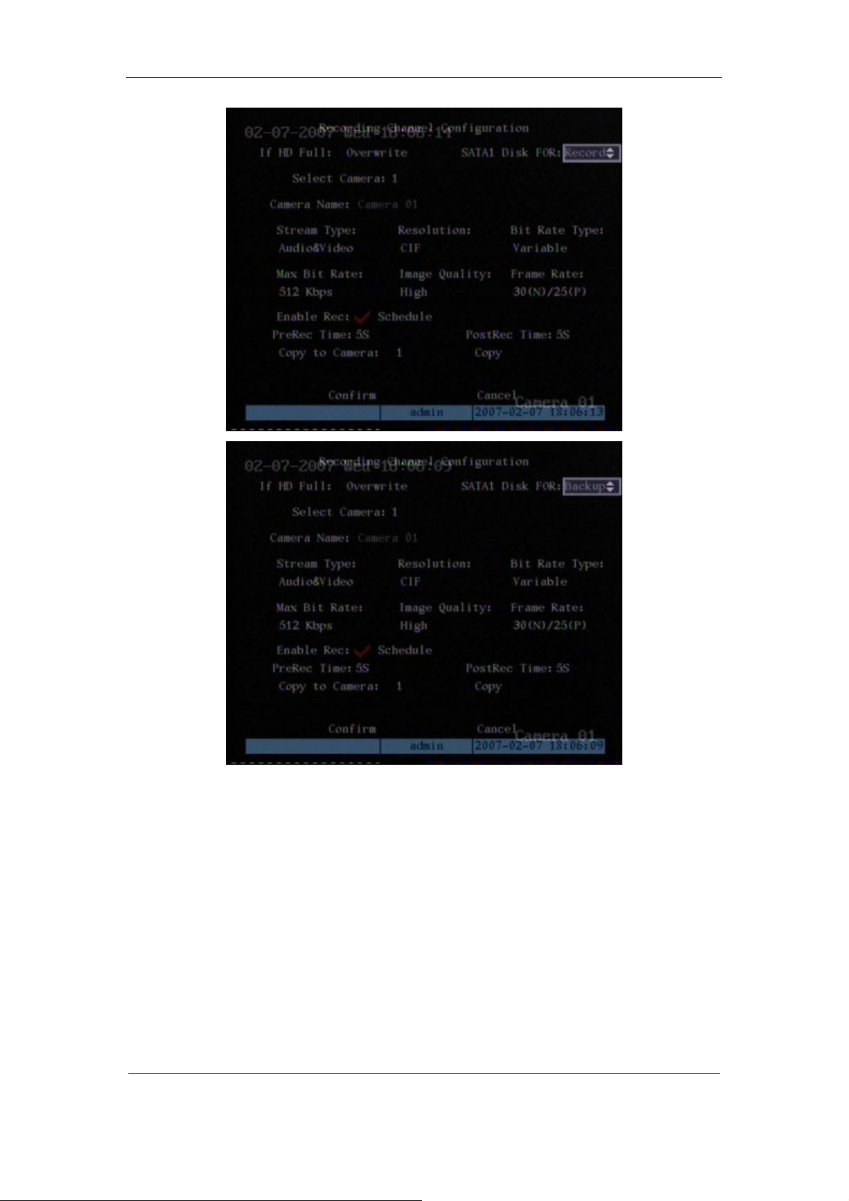
4. Supports E-SATA HDD backup
E-SATA interface in QSD42208, QSC26408, and QSC26416 model DVRs is optional. 1st
internal SATA interface can be extended to E-SATA (external SATA) interface. In DVR
“Recording” menu, you can select 1st SATA HDD as either “Recording” or “Backup” work mode.
)
)
Page 4 Total 121
User Manual for Commercial Series Net DVR
If you select “Backup” mode, in D VR “Playback” menu, you can select SATA HDD for
backup.
5.Solved some old version bugs
VGA black screen and Aux audio output issues
Page 5 Total 121

User Manual for Commercial Series Net DVR
Chapter 1 Product Introduction
1.1 Summary
The Commercial series network digital video recorder is a n excellent digital surveillance product.
It uses the embedded MCU and embedded operating system (RTOS), combining the most
adva nced technology in the Information Industry such as vide o and audio encoding/decoding, ha rd
disk recording and TCP/IP. The firmware is burned into flash memory, more stable and reliable.
The Commercial series device has both the features of digital video recorder (DVR) and
digit al vi de o server (D VS) . It ca n wor k st a nd a lo ne, a l so b e us ed t o b ui ld a p ower f ul s ur vei l la nce
network, widely used in banking, telecommunications, transportation, factories, warehouses,
irrigation, etc.
1.2 Features
Compression
l Supports 16 channnels video input (PAL/NTSC) at most. Each channel is independent,
H.264 hardware compression and real time (PAL: 25 FPS, NTSC: 30FPS). Support both
variable bitrate and variable frame rate.
l Supports 16 channels audio input at most. Each channel is independent, OggVorbis
compression and bitrate is 16Kbps.
l Compresse d video a nd audio a re syn chrono us. You ca n select either mixed st ream or
only vide o stream.
l Supports 4CIF, DCIF, 2CIF, CIF and QCIF resolution (depending on model).
l Supports multi area motion detection.
l Supports OSD and changeable OSD position.
l Supports LOGO and changeable LOGO position.
Local functions
Record
l Supports multiple record type, including real time, manual record, motion detection,
external alarm, motion&alarm, motion|alarm.
l Supports 8 SATA HDDs and each HDD can support 2000GB maximum.
l Supports FAT32 file system.
l Supports HDD S.M.A.R.T technology.
l Supports cycle or none cycle record.
l Supports backing up the recorded files and clips. Supports USB flash memory, USB
HDD, USB CD-R/W, USB DVD-R/W, SATA DVDRW/CDRW HDD for backup.
Page 6 Total 121

User Manual for Commercial Series Net DVR
Preview and playback
l Supports BNC analog moniotor and VGA output for main output
l Supports one aux video and audio input
l Supports multiple preview modes.
l Supports sensitive area mask.
l Supports camera spiteful block alarm.
l Supports 2-ch synchronous playback. Support play forward, backward, pause, frame by
frame, etc.
l Supports play back by files or by time.
l Displays local record status.
PTZ
l Support s man y PTZ pr otocol s.
l Supports preset, sequence and cruise.
Alarms
l Supports exception alarm, motion detection alarm, external alarm, etc.
Others
l Supports IR control.
l Supports RS-485 keyboard.
l Supports multi-level user management.
Network
l Supports TCP, UDP, RTP, Multicast for network preview.
l Supports PPPoE for broad band access.
l Supports PSTN for narrow band access.
l Supports remote parameters setup.
l Alarm information can be sent to remote center.
l Network control PTZ.
l Network record real time stream.
l Network downl oad and pla yback of the r ecorded files in DVR.
l Remotely upgrade the firmware.
l RS-23 2 suppor ts tra nsparent chann el funct ion so t hat th e remote PC can us e DVR t o
control serial devices.
l Supports bi-directional voice talk or one-way voice broadcast.
l Supports IE to preview and config DVR.
l Support log.
Development support
l Provides networ k S DK.
l Pr ovides client demo source code.
Page 7 Total 121

User Manual for Commercial Series Net DVR
Chapter 2 Installation
Warning: Before you install the DVR, please make sure the power to the DVR is
switched off.
2.1 Checking the DVR and Its Accessories
When you ge t the product , check that all the items a re incl uded in your product pa ckage.
There is a list in the package. If any of the items are missing, please contact your dealer.
2.2 HDD Installation
Installation notice
The DVR has no HDD when leaving factory. Based on the record schedule, you can calculate
the total capacity you need (refer to Appendix A). Please ask the specialist to disassembly the
DVR a nd insta ll HD D. If the vendor you pur cha sed the DVR fro m did n ot incl ude a H DD have
HDD installed by qualified technicians.
Installation instrument
One Phillips screw driver.
HDD installation
1. Open the DVR box.
2. Take off the HDD mounting plate.
3. Place the HDD on the mounting plate and attach it with screws.
4. Attach the mounting plate in the DVR.
5. Connect the ATA data cable correctly.
6. Plug the HDD power connector into the HDD.
7. Cover and re-attach the DVR box lid.
Note: After you install the HDDs, you must format them. Please re fer to section 6.4. If your
vendor supplied the DVR with HDDs this may have already been done for you.
Page 8 Total 121
User Manual for Commercial Series Net DVR
2.3 Rear Panel Description
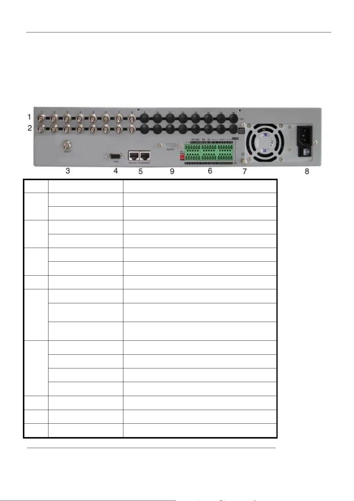
2.3.1 8-ch QSD42208 Rear Panel
Index Physical Interface Description
Video Input
1
Loop Back Ports
2
Main video Output
3
4
VGA Interface
RS-232/Keyboard
5
Interface
RJ45 Ethernet Port
Keyboard Interface
RS-485
6
External Alarm Input
Standard BNC.
Standard BNC.
Connect CCTV monitor, output video a nd menu.
VGA display.
Connect RS-232 devices. Refer to Appendix B for pin
definition.
Connect network devices. Refer to Appendix B for pin
definition.
Can use Hikvision DS-1000K1, DS-1002K1, DS1003K1
PTZ connection. Using T+/T- to connect PTZ.
4 sensor alarm in.
Relay Output
7
GND
8
AC Input
9
E-SATA
2 replay output .
Ground
100~240VAC
Optional. Extend 1st internal SATA to E-SATA.
Page 9 Total 121
User Manual for Commercial Series Net DVR
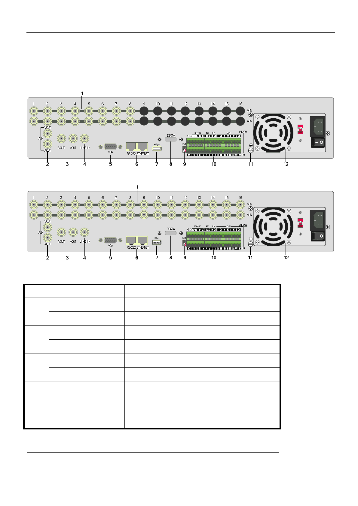
2.3.2 8-ch/16-ch QSC26408/16 Rear Panel
QSC26408 Rear Panel
QSC26416 Rear Panel
Index Physical Interface Description
Video Input
Standard BNC.
1
Audio Input
Aux video Output
Standard BNC.
Spot monitor for video preview and playback.
2
Aux audio Output
Main video output
Spot monitor for audio preview and playback.
Mai n monitor for vide o and me nu.
3
Main audio output
4
Line In
5
VGA Interface
6
RS-232
Mai n monit or for audi o previ ew an d playb ack.
Audio line input for voice talk.
VGA display.
Connect RS-232 devices. Refer to Appendix B for pin
definition.
Page 10 Total 121

User Manual for Commercial Series Net DVR
Connect network devices. Refer to Appendix B for pin
7
8
9
10
11
12
RJ45 Network Port
USB Interface
E-SATA
SW1
RS-485
Keyboard Interface
External Alarm Input
Relay Output
GND
AC Input
definition.
USB memory disk, USB HDD, USB CD-R/W, USB DVD
or USB mouse.
Optional. Extend 1st internal SATA to E-SATA.
RS-485 terminal resistor switch. Default is off. The
resistor is 120Ohm.
PTZ connection. Using T+/T- to connect PTZ.
Using D+/D- for keyboard and DVR cascade connection.
Can use Hikvision DS-1000K1, DS-1002K1, DS1003K1
16 sensor alarm in.
4 replay output .
Ground
100~240VAC
Page 11 Total 121
User Manual for Commercial Series Net DVR
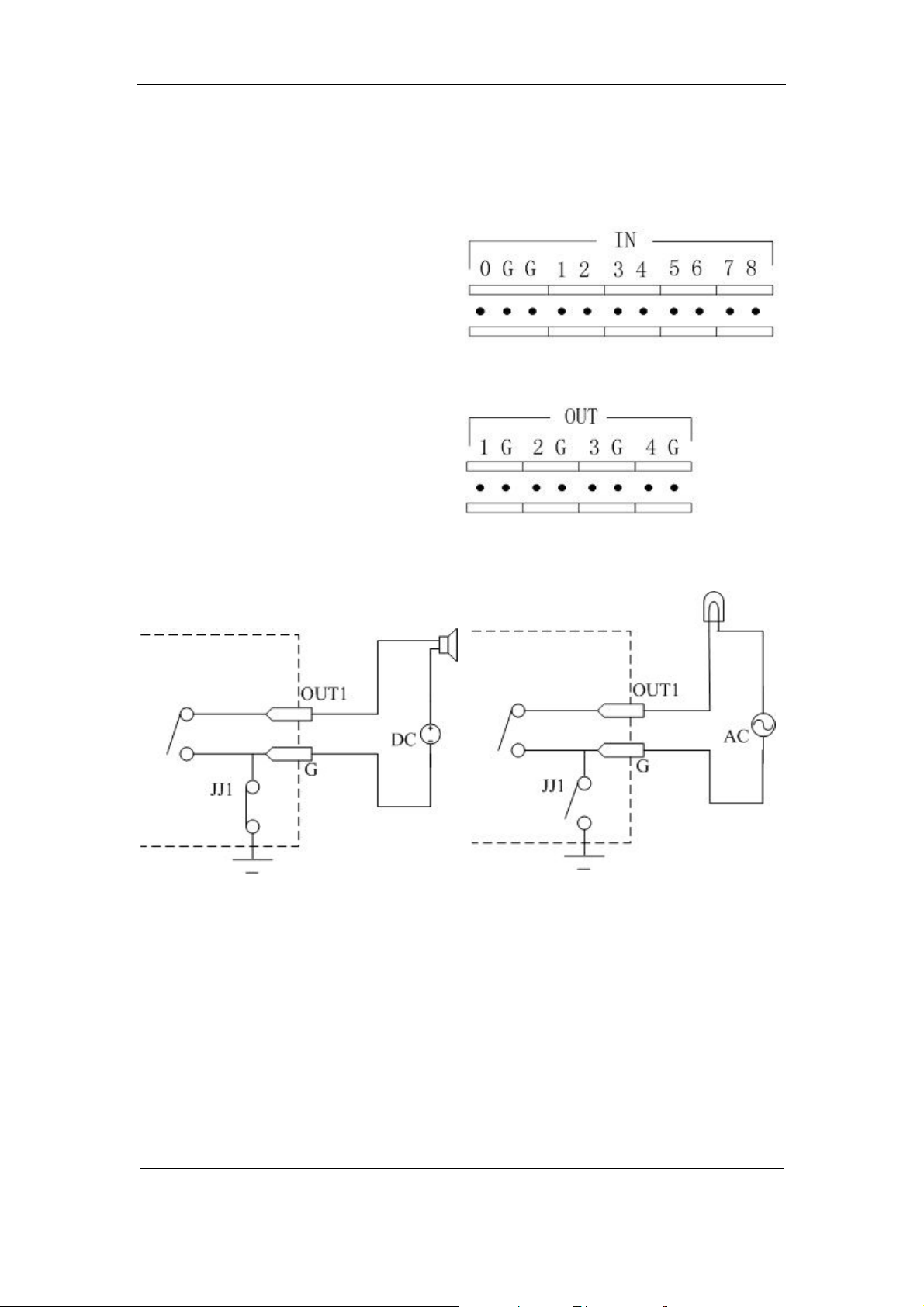
2.4 External Alarm In/Out Connection
Alarm input port (drp node):
G (GND): Connect the GND of sensor.
1~8: Alarm input, support normal
open/normal close.
0: Reserved.
Alarm output:
1G~4G: 4 relay output.
Alarm output connection
Please note the usage of jumper JJ1. If you use DC, either connection is OK. We suggest you
use DC under 12V, 1A.
If you use AC, please open the jumper. There are 4 jumpers (JJ1, JJ2, JJ3 and JJ4) on DVR
main board, corresponding with 4 alarm output. The default is closed.
Warning: If you use AC input for relay outpu t, please open the jumpers.
Page 12 Total 121
User Manual for Commercial Series Net DVR
Chapter 3 Operational Instructions
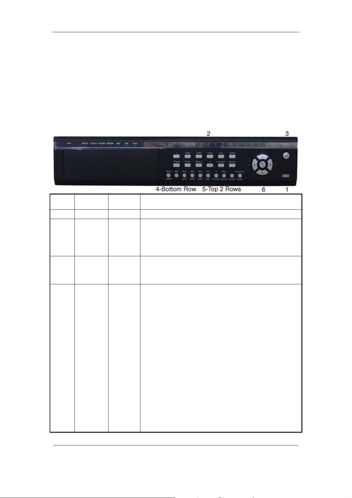
3.1.1 8-ch QSD42208 Front Panel
Index Type Name Description
1 USB Port USB flash drive, HDD, DVDRW/CDRW or Mouse
2 Status
Lamps
3 POWER POWER Device switch with power indicator lamp. Green means DVR is
4 Compound
Keys
1-8 Shows channel 1-8 status. Green means recording; Red mean s
network transmission; Orange means recording and network
transmission. Lamp twinkle and red means the corresponding
HDD has error.
working; Red mean s DVR is powered off; No light means n o
power is supplied.
MENU
ESC
PLAY
REC
EDIT
PTZ
A
1. Switch preview mode into menu;
2. Brush control short key【WIPER】.
Cancel and back to parent menu.
1. Local playback;
2. 【AUTO】in PTZ mode.
1. Man ual r ecord;
2. 【SHOT】in PTZ mode (adjust preset).
1. In edit state, delete current cursor charact er;
2. 【IRIS+】 in PTZ control;
1. Select ü or × to enable or disable.
1. Enter into PTZ control mode;
Page 13 Total 121

User Manual for Commercial Series Net DVR
5 Input
Keys
PREV
INFO
Main/Aux
Numeric
Keys
F1
F2
2. 【IRIS-】in PTZ control.
1. Input switch (number, lower case, upper case and symbol);
2. 【FOCUS+】in PTZ control;
3. In preview mode, display or hide the channel status bar.
1. Mul ti screen preview switch;
2. Switch menu mode into preview;
3. 【FOCUS-】in PTZ control.
【ZOOM+】in PTZ control.
1. 【ZOOM-】in PTZ control.
2. Switch main/aux video output control mode.
Input number, lower case, upper case character and symbols.
【LIGHT】in PTZ control.
6 Control
Keys
Direction
Keys
ENTER
【AUX】in PTZ control.
Composed of 【á】,【â】,【ß】and【à】.
1. Menu mode, use【ß】/【à】 to select 【á】/【â】 t o
edit;
2. PTZ dir ection control;
3. Pla yback speed contr ol.
1. Menu confirmation;
2. Select ü or × to enable or disable;
3. Pause playback.
Page 14 Total 121

User Manual for Commercial Series Net DVR
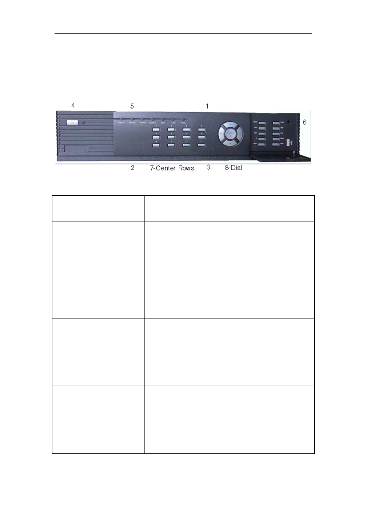
3.1.2 8-ch QSC26408 Front Panel
Index Type Name Description
1 IR receiver.
2 Status
Lamps
3 Status
Lamps
4 POWER POWER Device switch with power indicator lamp. Green means DVR is
5 Status
Lamps
6 Command
Keys
1-8 Shows ch annel 1- 8 status. Green mean s recording; Red means
network transmission; Orange means recording and network
transmission. Lamp twinkle and red means the corresponding
HDD has error.
9-16
(Previous
model
QSC26416)
READY
STATUS
ALARM
MODEM
HDD
LINK
Tx/Rx
MENU
ESC
PLAY
Shows ch annel 1 -16 status. Green mean s recordin g; Red mean s
network transmission; Orange means recording and network
transmission.
working; Red means DVR i s powered off; No ligh t means n o
power is supplied.
DVR is ready.
Green means you can use IR remote control.
Red means there is an alarm.
Green mean s modem conn ecti on an d dial -up successfu l.
Twinkle in red means reading or writing HDD.
Green means net work is OK.
Twinkle in green means da ta is bein g transmitt ed.
1. Switch preview mode into menu;
2. Brush control short key【WIPER】.
Cancel and back to parent menu.
Page 15 Total 121

User Manual for Commercial Series Net DVR
REC
EDIT
PTZ
A
PREV
INFO
Main/Aux
1. Local playback 2.【AUTO】in PTZ mode.
1. Man ual r ecord;
2. 【SHOT】in PTZ mode (adjust preset).
1. In edit state, delete current cursor charact er;
2. 【IRIS+】 in PTZ control;
2. Select ü or × to enable or disable.
1. Enter into PTZ control mode;
2. 【IRIS-】in PTZ control.
1. Input switch (number, lower case, upper case and symbol);
2. 【FOCUS+】in PTZ control;
3. In preview mode, display or hide the channel status bar.
1. Mul ti screen preview switch;
2. Switch menu mode into preview;
7 Input
Keys
Control
Keys
Numeric
Keys
F1
F2
Direction
Keys
ENTER
3. 【FOCUS-】in PTZ control.
【ZOOM+】in PTZ control.
3. 【ZOOM-】in PTZ control.
4. Switch main/aux video output control mode
Input number, lower case, upper case character and symbols.
【LIGHT】in PTZ control.【AUX】in PT Z control.
Composed of 【á】,【â】,【ß】and【à】.
1. Menu mode, use【ß】/【à】 to select 【á】/【â】 to
edit;
2. PTZ dir ection control;
3. Pla yback speed contr ol.
1. Menu confirmation;
2. Select ü or × to enable or disable;
3. Pause playback.
Page 16 Total 121
User Manual for Commercial Series Net DVR
3.1.3 16-ch QSC26416 Front Panel
Index Type Name Description
1 IR receiver.
2 Status
Lamps
3 Status
Lamps
4 POWER POWER Device switch with power indicator lamp. Green means DVR is
5 Status
Lamps
6 Command
Keys
1-8 Shows channel 1-8 status. Green means recording; Red means
network transmission; Orange means recording and network
transmission. Lamp twinkle and red means the corresponding
HDD has error.
9-16 Shows ch annel 1-1 6 status. Green means r ecording; Red means
network transmission; Orange means recording and network
transmission.
working; Red means DVR is powered off; No light means no
power is supplied.
READY
STATUS
ALARM
MODEM
HDD
LINK
Tx/Rx
MENU
ESC
PLAY
REC
DVR is ready.
Green means you can use IR remote control.
Red means there is an alarm.
Green mean s modem conn ecti on an d dial -up successfu l.
Twinkle in red means reading or writing HDD.
Green means net work is OK.
Twinkle in green means da ta is bein g transmitt ed.
1. Switch preview mode into menu;
2. Brush control short key【WIPER】.
Cancel and back to parent menu.
1. Local playback;
2. 【AUTO】in PTZ mode.
Page 17 Total 121

User Manual for Commercial Series Net DVR
EDIT
PTZ
A
PREV
INFO
Main/Aux
1. Man ual r ecord;
2. 【SHOT】in PTZ mode (adjust preset).
1. In edit state, delete current cursor charact er;
2. 【IRIS+】 in PTZ control;
3. Select ü or × to enable or disable.
1. Enter into PTZ control mode;
2. 【IRIS-】in PTZ control.
1. Input switch (number, lower case, upper case and symbol);
2. 【FOCUS+】in PTZ control;
3. In preview mode, display or hide the channel status bar.
1. Mul ti screen preview switch;
2. Switch menu mode into preview;
3. 【FOCUS-】in PTZ control.
7 Input
Keys
8 Control
Keys
Numeric
Keys
F1
F2
Direction
Keys
ENTER
【ZOOM+】in PTZ control.
5. 【ZOOM-】in PTZ control.
6. Switch main/aux video output control mode.
Input number, lower case, upper case character and symbols.
【LIGHT】in PTZ control.
【AUX】in PTZ control.
Composed of 【á】,【â】,【ß】and【à】.
1. Menu mode, use【ß】/【à】 to select 【á】/【â】 to edit;
2. PTZ dir ection control;
3. Pla yback speed contr ol.
1. Menu confirmation; 2. Select ü or × to enable or disable;
3. Pause playback.
Page 18 Total 121

User Manual for Commercial Series Net DVR
3.2 Remote Control
Index Name Description
1 POWER Turnoff device.
2 DEV Enable/Disable IR remote control
3 Numeric Keys Same as numeric keys of fron t p anel.
4 EDIT Same as EDIT key of front panel.
5 A Same as A key of front panel.
6 REC Same as REC key of front panel.
7 PLAY Same as PLAY key of front panel.
8 INFO Same as INFO key of front panel.
9 VOIP
10 MENU Sam e a s MENU ke y of front panel.
11 PREV Same as PREV key of front pan el.
12
Dir ection Keys
ENTER
Same as [Main/Aux] key of front
panel.
Same as direction keys and enter key of
front panel.
Page 19 Total 121

User Manual for Commercial Series Net DVR
13 PTZ Same PTZ key of front panel.
14 ESC Same as ESC key of front panel.
15 Reserved
16 F1
17 Lens control
18 F2
Same as【F1】key of front pan el.
IRIS, FOCUS ZOOM for lens control
of PTZ ca mera.
Same as【F2】key of front pan el.
Loading the batteries into the Remote Control
1. Remove the battery cover.
2. Insert the battery. Please make sure the poles (+ and -) are correctly positioned.
3. Replace the battery cover.
Start to use the Remote Control
Press【DEV】key, i nput the DVR devi ce ID (defa ult is “88 ”, can b e chan ged i n “Di splay”
menu) and then press【ENTER】key. If the “STATUS” lamp of DVR front panel turns to green, it
means you can use IR controll er to operate thi s DVR.
Stop using the Remote Control
When remote control status is on, press【DEV】ke y again, the “STATUS” lamp will be turned
off, then the remote control can not control this DVR.
Switch the DVR off
When remote control status is on, press【POWER】key for several seconds, the DVR will be
powered off.
When the Remote Control can not work normally
l Check batteries pole positions.
l Check the remaining charge in the batteries.
l Check to see the remote control sensor is covered.
If the problem is still exists, please contact administrator.
Page 20 Total 121

User Manual for Commercial Series Net DVR
3.3 Menu Description
3.3.1 Menu Items
Menu Name Function Menu Name Function
Camera name and position setup
Adjust Brightness, Contrast, Hue
and Saturation
OSD Display mode, position and
OSD format setup
Mask area setup
View tampering area and response
setup
Video signal loss
Motion detection sensitivity, area
and response setup
DVR IP address
DNS IP
Multicast IP address
Remote host IP and port
NAS I P and directory
PPPoE username and password
Exceptions type
Exceptions response
RS232 parameters
RS232 work mode
Add or delete user
Password setup or modification
User rights setup
Display
Recording
Alarms
PTZ
Preview
Video standard
Brightness
Menu transparency
Unit name
Device ID
Require password
Screen saver ti me
VGA resolution
Date and Time
Overwrite/Stop recording
Resolution and recording
parameters setup
Record schedule
PreRecord time
PostRecord time
Alarm input type (Normal open/
Normal close)
Alarm response and PTZ linkage
Alarm output and schedule
PTZ parameter s
Preset setup
Sequence setup
Cruise setup
Preview mode
Switch time
Enable/Disable audio preview
Preview layout
Image
Network
Exceptions
RS232
User
Password
Page 21 Total 121
User Manual for Commercial Series Net DVR
Text input mode
Transaction
ATM IP address
ATM type
T ext information
3.3.2 Menu Operation
How to enter into menu mode
l Press【MENU】key to enter into DVR main menu.
l Press【PLAY】 short key to enter i nto playba ck menu.
Utilities
Restore parameters
Upgrade firm ware
HDD management
Clear alarm output
Reboot
Power off
View log
System information
l Perss【REC】short key to enter into manual record menu.
l Perss【PTZ】s hort ke y to ent er int o PTZ co ntrol interfa ce.
Notes: You must input user name and password. The default user name is “admin” and
password is “12345”.
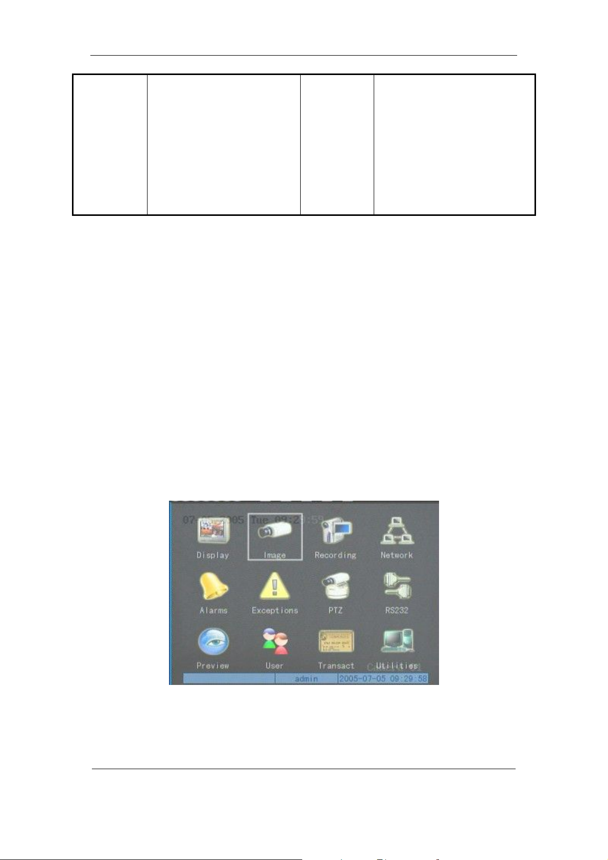
Main Menu Description
The main menu interface is:
There is one rectanglar frame called “Active Frame”. It can be moved from one icon to
another by usi ng 【à】or【ß】key. When the “Active Frame” is located on an icon, you can press
Page 22 Total 121

User Manual for Commercial Series Net DVR
【ENTER】key to e nt er int o t he s ec on dar y me nu. F or e x ampl e, mov e t he “Act ive Fr a me” t o t he
“Ima ge” icon, press 【ENTER】to enter into the secondary menu show below:
Each menu c ontains different kinds of i tems. There is a rectangular frame called “ Active
Frame” which is pointing to the selected item. This “Active Frame” can be moved by 【à】or【ß】
keys. There are such kinds of menu items:
a) Che ck B ox: Pr ovi de 2 o ptio ns, “ ü” means enable and “×” means dis ab le. You ca n us e
【ENTER】or【ED IT】key to swi tch over.
b) List Box: Provides more than 2 options. However, only one of them can be selected. You
can use 【↑】and【↓】to select one option. For example, on the right side of “Select
Camera”, there is a list box for you to select one camera.
c) Edit Box: This is for you to input characters. Press【EDIT】key to enter into edit status,
you can input characters as follows:
i. Press【A】key to select number, upper case, lower case or symbols;
ii. Use【à】and【ß】keys to move cursor;
iii. Use【EDIT】key to delete the charcter in front o f cursor;
iv. Press【ENTER】or【ESC】to exit edit.
d) Button: Excute a special function or enter into next sub-menu. For example, press
“Policy” button to enter into sub-menu. Press【Confirm】to save pa ramet ers and return
Page 23 Total 121

User Manual for Commercial Series Net DVR
to par ent menu. Press【Cancel】button to cancel and return to parent menu. The button in
grey means it can be operated only after it is enabled.
How to exit menu
Press【PREV】key to exit menu and return to previ ew mo de.
Page 24 Total 121

User Manual for Commercial Series Net DVR
3.4 Character Input
In th e men u inter face, if y ou ent er int o edit stat us (f or e xampl e, in t he “ camera name” edit
box), at the bottom of screen, the input status appears:
Here you can press numeric keys to input digital numbers.
Press【A】key to change input methods. You can select “number”, “Uppercase”, “Lowercase”
or “Symbol”.
Uppercase
Lowercase
Symbol
Ther e a r e 24 s y mb ol s i n a l l. T he y a r e di vi d e d i nto 4 pa ge s , a n d y o u can use【0 】key t o g o t o t he
next page.
Page 25 Total 121

User Manual for Commercial Series Net DVR
Chapter 4 Basic Operation Guide
4.1 Power on
Note: Please make sure the power supply matches DVR and AC cable is connected
correctly. Before switching DVR on, please connect one monitor with VOUT or VGA
interface. Otherwise, you can not see graphic user interface and can not operate.
If【POWER】lamp is off, please check the following:
Step1: Connect AC cable correctly;
Step2: Switch on the power button on the rear panel.
If【POWER】lamp is in red, just press 【POWER】button to start DVR.
When DVR is started,【POWER】lamp is gr ee n. O n t he monit or or VGA dis pla y, DSP an d
HDD initialization process will be shown.
The first line represents DSP initialization. If the DSP icon is “×”, it mea ns t ha t t he D SP ha s
an initialization error, please contact administrator at once.
The s econ d line r epres ents HDD i nitia liza tion. Ic ons of SATA ha rd dri ves ar e dis playe d. If
the HDD icon has a “×”, it means the corr esp ondi ng HD D is not i nsta lled or n ot det ect ed. I f the
HDD is installed but not detected, please contact administrator.
Note: If HDD is not installed or not detected, DVR will beep for alarm. You can disable the
alarm option in “Exceptions” menu.
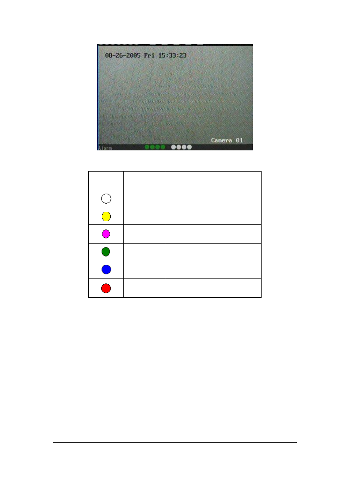
4.2 Preview
DVR will enter into preview mode after it is started.
On preview screen, you can see date, time, camera name and camera status icon.
Set system date and time in “Display” menu, refer to section 5.2.9; Change camera name in
“Image” menu, refer to section 5.3.2.
In the screen, it will dis play record and alarm status of each ca mera. Thes e two kinds of
status will switch over automatically.
Page 26 Total 121

User Manual for Commercial Series Net DVR
Press【A】key to display or hide the camera status bar.
Camera record status is:
Icon Icon Color Status Description
White No video signal
Yellow Vdieo input
Pink Manual recording
Green Real time recording
Blue Motion detect r ecordin g
Red External alarm recording
Page 27 Total 121
Camera alarm status is:
Icon Icon Color Status Description
User Manual for Commercial Series Net DVR
White Video signal lost
Yellow View tampering alarm
Pink Motion&External alarm
Green No alarm
Blue Motion alarm
Red External alarm
Press numeric keys to switch to individual camera preview. If DVR has less than 10 channels,
press one numeric key to switch corresponding channel. For example, press【2】key to preview 2nd
camera. If DVR has 10 or more than 10 channels, press two numeric keys to switch to
corresponding channel. For example, press 【0】【 2 】 to preview 2nd camera; and press 【1】
【2】keys to preview 12th camera.
Press【EDIT】key to manually cycle preview. You can set the auto preview mode in
“Preview” menu, refer to section 5.11.
Press【PREV】key to switch multi-screen perview.
Page 28 Total 121
User Manual for Commercial Series Net DVR
4.3 User name and password
Note: When DVR is delivered from factory, there is only one default administrator
named “admin”, and password is “12345”. The administrator ’s name can not be modified,
while the password can be modified. The administrator can create 15 users and define their
user rights.
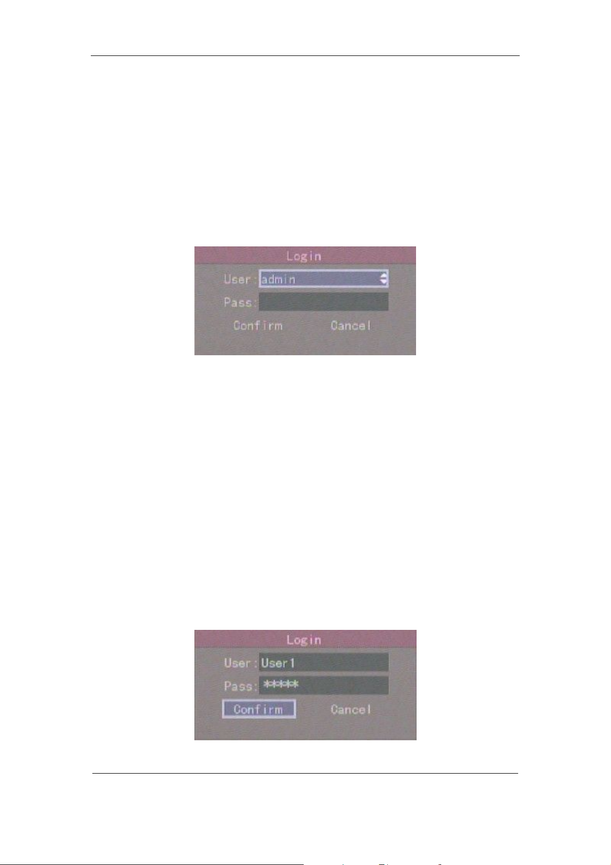
Login
Login dialog box:
Use【á】/【â】keys to sel ect one user, perss【à】key to enter into “Password” edit box, input
corr espon di n g passw ord, pr es s【ENTER】key to exit edit box. The “Active Frame” will be moved
to “Confirm” button. Press【ENTER】key to enter into main menu. If there is beeper alarm, it
means the user name a nd passw ord do not match. After three inc orrect trys the D VR wil l enter
into previ ew mode.
Modify password
For those users created by admin, they can modify their password as follows:
Step1: Enter into main menu
Press【MENU】key, in the logi n dialog, s elect your user name, i nput t he cor rect password, you
can e nter into t he main menu.
Page 29 Total 121
User Manual for Commercial Series Net DVR
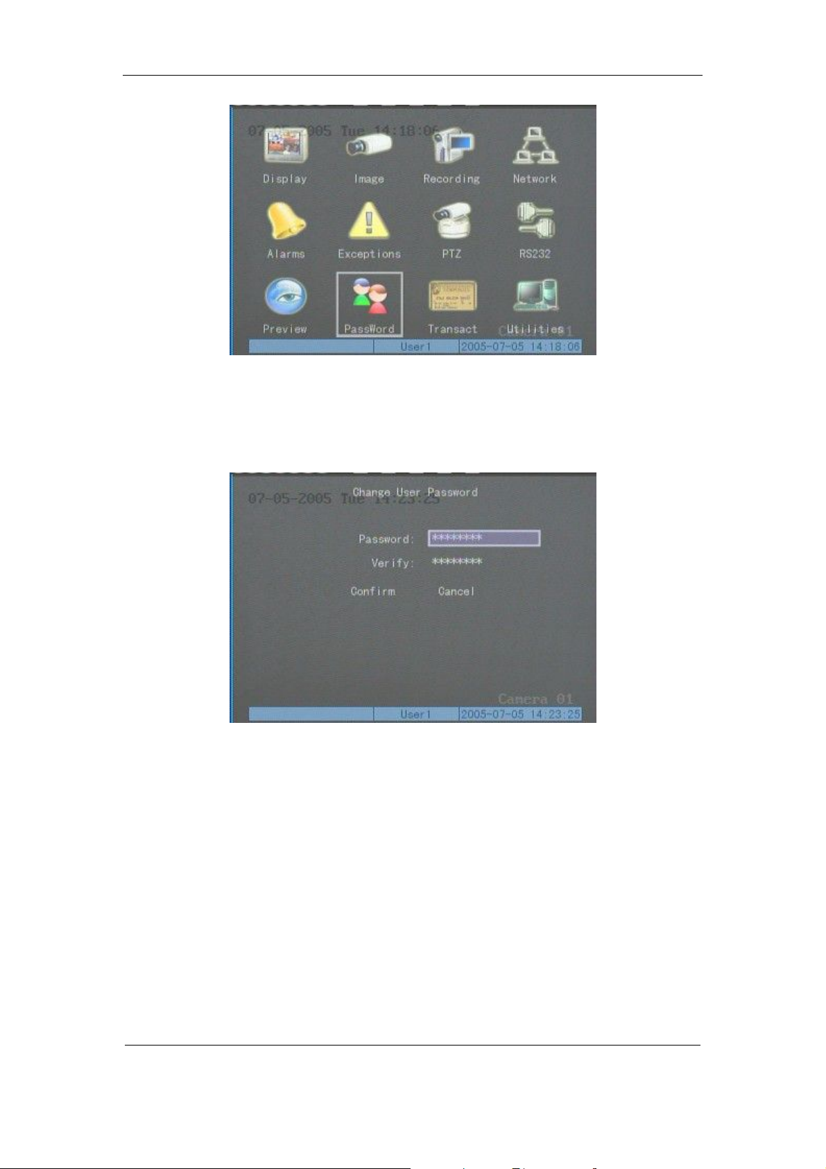
Setp 2: Enter into password modification menu
Move the “Active Frame” to “Password” icon by using【à】/【ß】keys. Press【ENTER】
key t o enter into password menu:
Step 3: Input new password
Press【EDIT】k ey t o ent er i nt o e dit b ox. You can use n umer ic ke ys t o i npu t new pa ssw or d.
The password can be null. It also can be 16 numerals. Press【ENTER】to exit edit box, and move to
“Verify” ite m to inpu t t he new pa ss w or d for ver if i ca ti on.
Note: In edit box, use 【à】/【ß】to move cursor and【EDIT】key to delete the numeral
in front of the cursor.
Step 4: Modify password successfully
Move the “Active Frame” to “Confirm” button, press【ENTER】key. If the password is
Page 30 Total 121
 Loading...