


H.264 Dual Stream Network DVR
8 Channel CIF@240fps & D1@60fps Digital Video Recorder
USER MANUAL
Model #:
QT428
www.q-see.com
Rev 8/2/2010

CONTACT US QT428 User Manual
Please contact a Q-See support representative first regarding any additional information you need
help with regarding product features, specification or assistance with setup.
Please contact us using the following methods with questions about your Q-See product.
Q-See Products
8015 E. Crystal Dr.
Anaheim, CA 92807
Email:
Customer Service
cs@dpsi-usa.com
Technical Support
ts@dpsi-usa.com
Online Live Web Chat Visit:
www.q-see.com
Telephone:
Customer Service
1.877.998.3440 x 538
Technical Support
1.877.998.3440 x 539
Fax:
1.714.998.3509

SAFETY INSTRUCTIONS QT428 User Manual
1. Electrical Safety
All installation and operation should conform to your local electrical safety codes.
We assume no liability or responsibility for any fires or electrical shock caused by improper
handling or installation.
2. Transportation Security
Avoid heavy stress, violent vibrations or contact with water during transportation, storage and
installation of this system.
3. Installation
Keep upright. Handle with care.
Do not provide power to the DVR prior to completing installation.
Do not place objects on the DVR.
4. Qualified Service Technicians
Any examination and repair work should be done only be a qualified service engineer.
We are not liable for any problems caused by unauthorized modifications or attempted repairs.
5. Environment
This product works in a temperature range of 14°F to 131°F (-10°C to 55°C)
This combo DVR should be installed in a cool, dry place away from direct sunlight and flammable
or explosive substances, etc.
6. Accessories
Make sure to only use accessories recommended by Q-See.
Before installation, check the package to verify that all the components are included.
Contact your local retailer ASAP if something is broken in your package.
CAUTION!
RISK OF ELECTRICAL SHOCK!

WARRANTY INFORMATION QT428 User Manual
Thank You for Choosing a Q-See Product!
All of our products are backed by a conditional service warranty covering all hardware for 12
months from the date of purchase. Additionally, our products also come with a free exchange
policy that covers all manufacturing defects for one month from the date of purchase. Permanent
upgrading service is provided for the software.
Liability Exclusions:
Any product malfunction or abnormalities in operation or damage caused by the following reasons
are not within the free service scope of our company:
(1) Equipment damage caused by improper operation.
(2) Improper equipment operation environment and conditions (e.g., improper power, extreme
environmental temperatures, humidity, lightning and sudden surges of electricity).
(3) Damage caused by acts of nature (e.g., earthquake, fire, etc).
(4) Equipment damage caused by the maintenance of personnel not authorized by Q-See.
(5) Product sold over 12 months ago.
In order to fulfill the terms of your warranty, you must complete the registration process after
purchasing our product. To do this, simply fill out the User’s Information Card below and fax or
mail it in to us at the information listed below. You can also register the product by going to
the www.q-see.com website and clicking on the Register link.

User’s Name
Mr./Mrs.
Company Name
Postal Address
Postal code
Phone Number
E-mail
Model Number of Product
Serial Number of Product
Purchase Date
Distributor
No part of this manual may be reproduced, copied, translated, transmitted, or published in any form or
accessories may be different according to the region you purchased our product. For more
PRODUCT REGISTRATION QT428 User Manual
Customer Information Card
The material in this document is the intellectual property of Q-See.
by any means without our company’s expressed written consent.
1. Our products are under continual improvement and we reserve the right to make changes without
notice. No guarantee is given as to the correctness of its contents.
2. We do not accept any responsibility for any harm caused by using our product.
3. The product picture may differ from the actual product, which is only for your reference. The
information on specific accessories, please contact your local distributor.
Copyright Reserved
2 | Page

TABLE OF CONTENTS QT428 User Manual
TABLE OF CONTENTS
1. INTRODUCTION ....................................................................................................................................... 6
1.1 DVR Introduction ...............................................................................................................................................6
1.2 Main Features ....................................................................................................................................................6
2. GETTING STARTED .................................................................................................................................... 8
2.1 Installing Hard Drive ...........................................................................................................................................8
2.2 Front Panel Instructions .....................................................................................................................................9
2.3 Rear Panel Instructions .................................................................................................................................... 10
2.4 Remote Control ................................................................................................................................................ 11
2.5 Control with Mouse ......................................................................................................................................... 12
2.5.1 Connect Mouse ......................................................................................................................................................................... 12
2.5.2 Use Mouse
................................................................................................................................................................................ 12
3. BASIC FUNCTION .................................................................................................................................... 14
3.1 Power On/Off .................................................................................................................................................. 14
3.1.1 Power On ................................................................................................................................................................................... 14
3.1.2 Power Off
3.2 Login ............................................................................................................................................................... 15
3.3 Live Preview .................................................................................................................................................... 15
3.3.1 Live Playback ............................................................................................................................................................................. 16
4. MAIN MENU SETUP GUIDE ..................................................................................................................... 17
4.1 Basic Configuration .......................................................................................................................................... 17
4.1.1 Setup ......................................................................................................................................................................................... 18
4.1.2 Time & Date
4.1.3 DST
4.2 Live Configuration ............................................................................................................................................ 20
4.2.1 Live ............................................................................................................................................................................................ 20
4.2.2 Host Monitor
4.2.3 SPOT
4.2.4 Mask
4.3 Record Configuration ....................................................................................................................................... 23
4.3.1 Enable ....................................................................................................................................................................................... 23
4.3.2 Record stream
4.3.3 Time
4.3.4 Recycle Record
4.3.5 Stamp
.................................................................................................................................................................................. 14
.............................................................................................................................................................................. 19
............................................................................................................................................................................................ 19
............................................................................................................................................................................. 21
.......................................................................................................................................................................................... 21
.......................................................................................................................................................................................... 22
........................................................................................................................................................................... 24
.......................................................................................................................................................................................... 25
.......................................................................................................................................................................... 25
........................................................................................................................................................................................ 26
4.4 Schedule Configuration .................................................................................................................................... 27
4.4.1 Schedule .................................................................................................................................................................................... 27
4.4.2 Motion
4.4.3 Sensor
3 | Page
...................................................................................................................................................................................... 28
....................................................................................................................................................................................... 28

TABLE OF CONTENTS QT428 User Manual
4.5 Alarm Configuration ......................................................................................................................................... 29
4.5.1 Sensor (to setup optional external motion sensors) ................................................................................................................. 29
4.5.2 Motion
4.5.3 Video Loss
4.5.4 Other Alarm
4.5.5 Alarm Out
4.6 Network Configuration ..................................................................................................................................... 35
4.6.1 Network .................................................................................................................................................................................... 35
4.6.2 Sub Stream
Email ................................................................................................................................................................................... 37
4.6.3
4.6.4Other settings
4.7 User Management Configuration ...................................................................................................................... 38
4.8 P.T.Z configuration ............................................................................................................................................ 40
4.9 Advanced .................................................................................................................................................... 44
4.9.1 Reset .......................................................................................................................................................................................... 44
Import/Export ..................................................................................................................................................................... 44
4.9.2
...................................................................................................................................................................................... 31
................................................................................................................................................................................. 33
.............................................................................................................................................................................. 33
.................................................................................................................................................................................. 34
................................................................................................................................................................................ 36
............................................................................................................................................................................ 37
5. RECORD, SEARCH, PLAYBACK AND BACKUP ............................................................................................. 45
5.1 Time Search ..................................................................................................................................................... 45
5.2 Event Search .................................................................................................................................................... 46
5.3 File Manager ................................................................................................................................................... 46
5.4 Backup ............................................................................................................................................................ 47
6. DVR MANAGEMENT ............................................................................................................................... 49
6.1 Checking System Information ........................................................................................................................... 49
6.1.1 System Information ............................................................................................................................................................. 49
Event Information ............................................................................................................................................................... 49
6.1.2
Log Information ................................................................................................................................................................... 50
6.1.3
Network information ........................................................................................................................................................... 50
6.1.4
Online Information .............................................................................................................................................................. 51
6.1.5
Manual Alarm ...................................................................................................................................................................... 51
6.1.6
Disk Manager ...................................................................................................................................................................... 51
6.1.7
Upgrade ............................................................................................................................................................................... 52
6.1.8
Logoff .................................................................................................................................................................................. 52
6.1.9
7. REMOTE SURVEILLANCE ......................................................................................................................... 53
7.1 Network Access ............................................................................................................................................... 53
7.2 Setting Up Remote Access ................................................................................................................................ 53
7.3 Port Forwarding ............................................................................................................................................... 62
7.5 Using the Remote Access Software
7
.6 Remote Playback and Backup ........................................................................................................................... 72
7.6.1 Remote Playback ....................................................................................................................................................................... 72
7.6.2 Remote Backup
................................................................................................................... 69
4 | Page
......................................................................................................................................................................... 76

TABLE OF CONTENTS QT428 User Manual
7.7 Remote System Configuration .......................................................................................................................... 77
8. MOBILE SURVEILLANCE .......................................................................................................................... 78
8.1 Phones with Windows Mobile Pro ............................................................................................................... 78
8.2 Phones with Symbian .................................................................................................................................. 80
8.3 For iPhone Mobile Clients ............................................................................................................................ 82
8.4 For Android Mobile Clients .......................................................................................................................... 86
9. PRODUCT SPECIFICATIONS ..................................................................................................................... 91
APPENDIX A: FAQ’s .................................................................................................................................... 92
APPENDIX B: CALCULATE RECORDING CAPACITY ......................................................................................... 94
APPENDIX C: COMPATIBLE USB DRIVES ...................................................................................................... 95
5 | Page

INTRODUCTION QT428 User Manual
1. INTRODUCTION
1.1 DVR Introduc t ion
This DVR uses high performance video pr ocessing chips and an embedded Linux system. It utilizes many advanced
technologies, such as standard H.264 with low bit rate, Dual Stream, SATA interface and VGA output. This DVR
system supports mouse controlled navigation and also can be accessed through IE browser with full remote control,
mobile viewing by cell phones, etc. This is an advanced technology DVR system which utilizes cutting edge
technology functions without compromising the stability of the system. It is ideally suited for use in such industries as
banking, telecommunication, transportation, f act or ies, warehouses, etc.
1.2 Main Features
COMPRESSION FORMAT
Standard H.264 compres sion with low bit rate and high image quality
LIVE SURVEILLANCE
Supports HD VGA output
Supports channel security by hiding live display
Displays the local record state and basic information
Supports full contro l w ith USB mouse
Supports digital zoom on Live and playback view locally and remotely.
RECORDING MEDIA
Supports one SATA HDD up to 2TB to record for a long time periods.
BACKUP
Supports backing up to USB 2.0 devices
Supports saving r ecor ded files with AVI format to a remote computer t hr ough internet
RECORDING & PLAYBACK
Record modes: Manual, S chedule, Motion detection and Sens or alarm recording
Ability to record in CIF resoluti on on some cameras and D1 on other s.
Supports recycl e after HD D is full
Resolution, frame rate and pict ur e quality are adjustabl e
128MB for every video file packaging
4 audio channels availa ble
Two record search modes: t ime sear ch and event search
Supports 8 screen playback local on DVR and 4 screens rem ot ely.
Supports deleting and locking the recorded files one by one
Supports remote p layback in Network Client thr ough LAN or internet
6 | Page

INTRODUCTION QT428 User Manual
ALARM
1 channel alarm output an d 8 channel alarm input available
Supports scheduling for motion detection and sensor alarm
Supports pre-recording and post recording
Supports linked chann els record ing once motion or alar m is triggered on designated channel
Supports linked PTZ preset, auto cruise and track of the corresponding channel
Ability to send Email notifi c at ion with picture when motion alarm is triggered.
PTZ CONTROL
Supports multiple PTZ protocols (PelcoP, PelcoD, LILIN, MINKING, NEON, STAR, VIDO, DSCP, VISCA, and
RANGE)
Supports 128 PTZ presets and 8 auto cruise tracks
Supports remote PTZ cont rol through internet
SECURITY
Customi ze user righ ts: log search, system setup, two way audio, file management, disk management, remote
login, live view, manual record, playback, PTZ control and remote live view
Supports 1 administ r at or and 15 users.
Supports event lo g rec or ding and checking, event s unlim ited
NETWORK
Supports T CP/IP, DHCP, PPPoE, DDNS protocols
Supports IE brows er t o do remote viewing
Supports a maximum of 10 connections simultaneously
Supports dual stream. Network stream is adjustable independently to fit the network bandwidth and
environment.
Supports picture snap and color adjustment in re m ot e liv e view
Supports remote ti m e and event search, and channel play back with picture snap
Supports remote PT Z control with preset and auto cruise
Supports remote full men u setup, changi ng all the DVR parameters r emotely
Supports mobile surveillance by smart phones, W in Mobile Pro, Symbian, iPhones, iPads and Android on 3G
networks
Supports CMS to man age multiple devices on the internet
Ability for admin to discon nect online users.
Ability for admin to allow u s er ac cess to specific cameras.
7 | Page

GETTING STARTED QT428 User Manual
2. GETTING STARTED
Check the unit and the accessories immediately af ter opening your system .
Please disconnect the po wer before connecting to other devices.
2.1 Installing Hard Drive
This device supports one SATA hard drive up t o 2TB.
Calculat e HDD capacity acco rding to the reco rding setting s. Please refer to “Appendix B Calculate Recording
Capacity”.
Step 1: Unscrew and Open the top cover
Step 2: Connect the power and data cables. Pl ace the HDD onto the bottom case as shown below.
Fig 0.1 Connect HDD
Step 3: Screw in the HDD as shown below.
Note: For easier installation, please connect the power and data cables first, and then screw the HDD to
base.
Fig 0.2 Screw in the HDD
8 | Page

Item
Number
-
DIRECTION/
MULTISCREEN
1.Change direction to select items
2. Change screen display mo de from 1/4/9/16 channel
To connect external USB devices like USB flash, U SB HDD for backup or update
GETTING STARTED QT428 User Manual
2.2 Front Panel Instructions
An illustration of the Front Pan el interface is shown as Fig 2.3:
Fig 0.3 Front Panel
Name/Symbol Description
1 LED INDICATORS Working indic at or s for power, HDD, NET, etc
2 POWER Power On/Off
3 RECORD Record Manually
4 PLAY Enter Play Interface
5 REW Rewind Key
6 FF Fast Forward
7 +/MENU Increase the value in setup/Enter menu in live view
8
9 STOP/ESC Quit play mode/Exit the current interface or status
10
11 ENTER Confirm selection
/BACKUP
Decrease the value in set up/ Ent er backup mode in live view
12
firmware
9 | Page

Item
Name
Description
1
Video out
Connect to monitor
Audio output, connect to the sound
box
3
Video in
Video input channels from 1-8
4
DC12V
POWER INPUT
5
VGA port
VGA output, connect to monitor
6
LAN
Network port
Connect USB mouse or connect
external USB devices
8
P/Z
Connect to speed dome
9
K/B
Connect to keyboard
1-ch relay output. Connect to external
alarm
11
+ 5V and GND
+5 V and Grounding
12
ALARM IN
Connect to external sensor1-4
13
Audio in
4 CH Audio input
GETTING STARTED QT428 User Manual
2.3 Rear Panel Instructions
Rear Panel Interface
An illustration of the rear Pan el i nt er f ace i s show n as Fig 2.4:
Fig 0.4 Rear Panel
2 Audio out
7 USB port
10 ALARM OUT
10 | Page

Soft switch off to stop firmware running. Do it before
power off.
information
3
REC Button
To record manually
4
Digital Button
Input digital or choose camera
5
Multi Screen Button
To choose multi screen display mode
6
SEARCH Button
To enter search mode
7
MENU Button
To enter menu
8
ENTER Button
To confirm the choice or setup
9
Direction Button
Move cursor in setup or pan/title PTZ
10
+/- Button
To increase or decrease the value in setup
To control playback, Fast forward/rewind/stop/single
frame play
12
AUDIO Button
To enable audio output in live mode
13
Auto Dwell Button
To enter auto dwell mode
14
BACKUP Button
To enter backup mode
To control PTZ camera:
Move camera/ZOOM/FOCUS/IRIS/SPEED control
GETTING STARTED QT428 User Manual
2.4 Remote Control
The remote control uses t w o AAA size batteries. Instructions for operation a r e as follows:
Step 1: Open the cover of the Remote Control
Step 2: Place batteries making sure the poles ar e correct (+ and -)
Step 3: Replace the battery cover
If the remote does not work check the following:
1. Check the pole position of t he bat t er i es
2. Check the remaining charge in the batteries
3. Check to make sure the s ensor on t he DVR is clear
4. If it still doesn't work, contact Q-See for a replacement
Figure 2-5 below illustrates the Remote Control functions as fo ll ow s:
Fig 0.5 Remote Control
Item Name Function
1 Power Button
2 INFOR Button
Get information about the DVR like firmware version, H DD
11 Playback Control Button
15 PTZ Control Button
11 | Page

GETTING STARTED QT428 User Manual
2.5 Control with Mo use
2.5.1 Connect Mouse
DVR supports USB mouse thr ough the port on the rear panel, p lea s e refer to Fig 2.4 Number 5.
Notice
1. Make sure the mouse plugs in the USB mouse port on the back of the DVR, not the front panel port.
2. Try a different mouse
2.5.2 Use Mouse
In Live:
Double-click left button on one camera to be full screen display. Double-click again to return to the previous screen
display.
Click right button to show the c ont r ol b ar at the bottom of the screen as Fig 4-1 main menu toolbar
Click right mouse again to hide t he control bar.
In Setup:
Click left button to enter. Click right button to cancel setup, or return to t he pr evious screen.
If you want to input values, move cursor to the blank and click. An input window will appear as shown in Fig2.6. It
supports numbers, letters and symbols.
: If mouse is not detected or doesn't work, check below ste ps:
Fig 0.6 Numbers and Letters Input Window
Users can change some values by the wheel, such as time. Move cursor onto t he value, and r oll the wheel when the
value blinks.
Also supports mouse drag. I.e. Set motion detection area: click customized, hold left button and drag to set motion
detection area. Set schedule: hold left button and drag t o set schedule time
12 | Page

GETTING STARTED QT428 User Manual
In playback:
Click left button to cho ose the options. Click right button to return to live view.
In backup:
Click left button to cho ose the options. Click right button to return to previous picture.
In PTZ control :
Click left button to cho ose the buttons to control the PTZ. Clic k r ight but t on t o return to live view.
Notice: Mouse is the def a ul t tool for all the operations below unless otherwise noted.
13 | Page

BASIC FUNCTIO NS QT428 User Manual
3. BASIC FUNCTION
3.1 Power On/Off
Before you power on the unit, pl ease make sure all the connections are good.
3.1.1 Power On
Step 1: Connect the power supply; switch on the power button near the power port on the rear panel
Step 2: The firmware will be loaded, and the power indicator will display blue
Step 3: At start up, a WIZZARD dialogue box will pop-up (refer to picture below) displaying time zone and time set up
information.
After the device powers on, if there is no menu or only displays live image, user can hold down ESC button to switch.
Notice: this unit can only display menu on VGA monitor or BNC monitor one at a time. If there is live im age
display without menu display, please check to see if other monitoring device has menu display first, or hold
down ESC key to wait for login dialog box to appear.
3.1.2 Power Off
User can power off the d evice by using remote contr ol, keyboar d or mouse.
By Remote Control:
Step 1: Press Power button, the Shut down window will appear, click OK, the unit will power off after firmware is shut
down.
Step 2: Disconnect the power.
By Keyboard and Mouse:
Step 1: Enter into
Step 2: Click OK, the unit will power off af ter firmware is shut down.
Step 3: Disconnect the power.
Menu, then select “Syst em Shut Down” icon, the Shut dow n w indow w ill appear
14 | Page

Symbol
Meaning
Symbol
Meaning
Manual record or time
recording
Alarm
recording
Yellow
Motion detection recording
Figure icon
Motion event
BASIC FUNCTIO NS QT428 User Manual
3.2 Login
User can login and logout of the DVR system. User cannot do any other opera tions ex cept ch ang ing t he multi-screen
display once logout. Admin has full control over DVR.
Fig 3-1 Login
Notice: the default user name a nd password is “admi n” and 123456”
For information on how to change password, add or delete users please refer to Fig 3.7 User
management configuration.
3.3 Live Preview
The explanation of symbo ls in the live preview interface:
Green
Fig 3-2 Live Preview Interface
Red
15 | Page

BASIC FUNCTIO NS QT428 User Manual
3.3.1 Live Playback
Click the Play
screen.
button to playback the record. Refer to Figure3-3. User can operate by cl i cking the buttons on the
Fig 3-3 Live Playback
16 | Page

MAIN MENU SETUP GUIDE QT428 User Manual
4. MAIN MENU SETUP GUIDE
Click right mouse or press ESC button on the front panel, the control bar will display on the bottom of the screen,
refer to Fig 4-1:
Fig 4-1 Main Menu Toolbar
Click icon beside the screen display mode, a channel select dialog will appear as below:
Take 8-channel DVR for example: user can tick off 8 channels form 1-ch to 8-ch at random to display the
live pictures. Then c lick
Click
icon, user can zoom in the live and playback images. When single image display, user can
button to confir m the setting.
select zoom in area by dragging mouse.
Click the Menu
panel or remote control will also disp lay the main interface.
button, the interface will pop-up as shown in Fig 4-2; press MENU button on the front
Fig 4-2 Main Menu
4.1 Basic Configuration
Basic configuration includes three sub menus: system, date& time and DST.
17 | Page

MAIN MENU SETUP GUIDE QT428 User Manual
4.1.1 Setup
Step1: Enter into Setup configurationbas i c configurationsetup; refer to Fig 4-3:
SETUP
Fig 4-3 Basic Configuration
Step2: In this interface user can setup the device name, device ID, video format, max network users, VGA resolution
and language. The explanations for each display are shown below:
Device name: the name of the device. It will display on the client end or CMS and help user to recognize the
device remotely.
Video format: two modes: PAL and NTSC. User can select the video format according to that of camera, in
USA and Canada we use NTSC cameras.
Password Check: i f you enable thi s option, user needs to inp ut user name a nd passw ord to do corresponding
operations in system confi gur at io n.
Show time: display time in live view.
Show wizard: check this item, an opening wizard will display with time zone and time setup infor m at ion
Max network users: set the maximum number of network connections
VGA resolution: the resolution of live display interface, options are: VGA800*600, VGA1024*768,
VGA1280*1024 and CVBS
Note: Switching between VGA and CVBS will change the menu output mode, please connect to
relevant monitor, VGA for VGA monitor, CVBS for TV or monitor that is connected using BNC adapter.
Language: setup the menu language.
Note: after changing the language and video o ut put, the device needs to restart.
18 | Page

MAIN MENU SETUP GUIDE QT428 User Manual
4.1.2 Time & Date
Step 1: Enter into system configurationbasic configur at iontime & date; refer to Fig 4-4:
Fig 4-4 Basic Configuration-Time & Date
Step 2: Set the date format, time format, time zone in this interface; Checkmark “sync time with NTP server” to
refresh NTP server date; user also can adjust system date m anually
Step 3: Click “default” button to restore default settings; click “apply” button to save the settings; click “exit” button to
exit current interface.
4.1.3 DST
Step1: Enter into system configurationbas ic configurationDST; refer to Fig 4-5:
Fig 4-5 Basic Configuration-DST
Step 2: In this interface, you can enable daylight saving time, time offset, mode, start & end month/week/dat e, etc.
Step 3: Click “default” button to restore default settings; click “apply” button to save the settings; click “exit” button to
exit current interface.
19 | Page

MAIN MENU SETUP GUIDE QT428 User Manual
4.2 Live Configuration
Live configuration includes four submenus: live, host monitor, SPOT an d mask.
4.2.1 Live
In this interface, user can set up camera names, adjust colors: br ightness, hue, saturation and cont r ast .
Step 1: Enter into system configurationlive configurationlive; refer to Fig 4-6:
Fig 4-6 Live ConfigurationLive
Step 2: Checkmark camera name; click “setting” button, a window will pop-up shown as Fig 4-7:
Fig 4-7 Live-Color Adjustment
Step 3: In this interface, user can adjust brightness, hue, saturation and contrast in live view; click “default” button to
restore default settings, click “OK” butt on t o save the settings.
Step 4: User can setup all channels with same parameters, checkmark “all”, then do relevant setup.
Step 5: Click “default” button to restore default settings; click “apply” button to save the settings; click “exit” button to
exit current interface.
20 | Page

MAIN MENU SETUP GUIDE QT428 User Manual
4.2.2 Host Monitor
Step 1: Enter into system configurationlive configurationhost monitor; refer to Fig 4-8:
Fig 4-8 Live Configuration-Host Monitor
Step 2: Select split mode: 1×1, 2×2, 2×3, 3×3, 4×4 and channel
Step 3: Dwell time: the time interval for a certain picture display before switching to next picture display
Step 4: Select the split mode, then setup cur rent p ict ure grou p. Cl ick
of pictures, click
Step 5: Click “default” button to restore default settings; click “apply” button to save the settings; click “exit” button to
exit current interface.
NOTE: If you have dual monitors Hos t m onitor needs to be main monitor.
4.2.3 SPOT
Step 1: Enter into system configurationlive configurationSPOT; refer to Fig 4-9:
button to set latter channel groups of pictures.
button to setup the prev iou s ch anne l groups
Step 2: Select split mode: 1×1 and channel
Fig 4-9 Live Configuration-SPOT
21 | Page

MAIN MENU SETUP GUIDE QT428 User Manual
Step 3: Dwell time: the time interval for a certa in picture display before switching to the next picture display.
Step 4: Select the split mode, then setup curr ent p ict ure grou p. Cl ick
of pictures, click
Step 5: Click “default” button to restore default setting; click “apply” button to save the setting; click “exit” button to
exit current interface.
To activate this setting, go to the main camera screen and click on the Dwell icon (Fig 4-1) . This will ma ke the camer a
rotate based on the setti ng in Main Monitor.
4.2.4 Mask
User can setup private ma s k ar ea on t he live image picture, maxi mum of three areas.
button to set the latter channel groups of pictures.
button to setup the previous channel groups
Fig 4-10 Live Configuration-Mask
Setup Mask Area: click Setting button, enter i nt o l ive image and press left mouse button and drag mouse to set
mask area, refer to picture below. Click Apply button to save the sett ing.
Delete Mask Area: select a certain mask area, click left mouse button to delete that mask area, click Apply
button to save the setting.
Setup Mask Area
22 | Page

MAIN MENU SETUP GUIDE QT428 User Manual
Live Image Mask Area
4.3 Record Configuration
Record configuration inc lu des five sub menus: enable, record bit rate, time, recycle record and stamp.
4.3.1 Enable
Step 1: Enter into system configurationrecord con figur at i onenable; refer to Fig 4-11:
Fig 4-11 Record Configuration-Enable
Step 2: Checkmark record, audio and record t i me
Step 3: User can setup all channels with same parameters, checkmark “all”, then do relevant setup.
Step 4: Click “default” button to restore default setting; click “apply” button to save the setting; click “exit” button to
exit current interface.
23 | Page

Parameter
Definition
fps
Range from 1-30 (NTSC) 1-25 (PAL)
Rate
Resolution
Supports CIF and D1
Quality
The quality of recorded images. The higher the value, the clearer the
: lowest, lower, low, medium, higher and
highest.
Encode
VBR and CBR
Max bit
2 Mbps
MAIN MENU SETUP GUIDE QT428 User Manual
4.3.2 Record stream
Step 1: Enter into system configurationrecord con figur at ionrecord bit rate; refer to Fig 4-12:
Fig 4-12 Record Configuration-Record Bit Rate
Step 2: Setup rate, resolution, quality, encode and max bit stream
Step 3: User can setup all channels with same parameters, checkmark “All”, then to do relevant setup.
Step 4: Click “default” button to restore default setting; click “apply” button to save the setting; click “exit” button to
exit current interface.
Note: if you set a value that is higher then maximum supported by the device, the value w ill be adjusted
automatically.
Definitions and descriptions of Record stream:
Range from: 1-30(NTSC)1-25(PAL)
recorded image is. Six options
Range from: 64 Kbps、128 Kbps、256 Kbps、512 Kbps、768 Kbps、1Mbps、
stream
24 | Page

MAIN MENU SETUP GUIDE QT428 User Manual
4.3.3 Time
Step 1: Enter into system configurationrecord con figur at ion time; refer to Fig 4-13:
Fig 4-13 Record Configuration-Time
Pre-alarm record time: set the record time before event happen i.e. record time before motion detection or
sensor alarm is triggered.
Post-alarm record: set the post recordi ng ti me aft er the alar m is finishe d, five optio ns: 10s, 15s, 20s, 30s and
60seconds.
Expire time: the hold time of saved records. When the set date has passed, the record files will be deleted
automatically.
Step 2: User can setup all channels with same parameters, checkmark “all”, then to do relevant setup.
Step 3: Click “default” button to restore default setting; click “apply” button to save the setting; click “exit” button to
exit current interface.
4.3.4 Recycle Record
Step 1: Enter into system configurationrecord con figur at i onrecycle record;
Step 2: Checkmark recycle record, the recycle record function will be enabled, it will overwrite the earlier recorded
files and keep recoding w hen HDD is full; if not enables the DVR will stop recording when HDD is full.
Step 3: Click “default” button to restore default setting; click “apply” button to save the setting; click “exit” button to
exit current interface.
25 | Page

MAIN MENU SETUP GUIDE QT428 User Manual
4.3.5 Stamp
Stamp:User can display the chan nel name and time stamp on vide o.
Step 1: Enter into system configuration record configuration stamp; refer to Fig 4-14:
Fig 4-14 Record Configuration-Stamp
Step 2: Checkmark camera name, time stamp; click Set button, user can use cursor to drag the camera name and
time stamp to random po sitions, refer to below Figures:
Before Drag After Drag
Step 3: User can setup all channels with same parameters, checkmark “all”, then to do relevant setup.
Step 4: Click “default” button to restore default setting; click “apply” button to save the setting; click “exit” button to
exit current interface.
26 | Page

MAIN MENU SETUP GUIDE QT428 User Manual
4.4 Schedule Configuration
Schedule configuratio n in c lud es three sub menus: schedule, motion and alarm.
4.4.1 Schedule
Step 1: Enter into system configurationschedule conf igurationschedule; refer to Fi g 4-15:
Fig 4-15 Schedule Configuration-Schedule
Step 2: Select channel, double-click and a dialog box will pop-up shown as Fig 4-16, user can edit week sched ul e:
Fig 4-16 Schedule-Week Schedule
① Click “add” but t on t o add a certain day schedule; cli ck “d elete” button to delete the select ed schedule;
Copy: user can copy the spec i fy s chedule to other dates.
Click “OK” button to save the s et t ing, click “Exit” button to exit curre nt int er f ace.
② User can apply the schedule setting of certain channel to other or all channels, just only select channel
and click “Copy” button.
Step 3: Click “default” button to restore default setting; click “apply” button to save the setting; click “exit” button to
exit current interface.
27 | Page

MAIN MENU SETUP GUIDE QT428 User Manual
4.4.2 Motion
Step 1: Enter into system configurationschedule conf igurationmotion; refer t o Fig 4-17:
Fig 4-17 Schedule Configuration-Motion
Step 2: The setup steps of motion are similar to schedule; user ca n r ef er t o 4.4.1 Sch edu le for deta ils.
Note: the default schedule of motion detection is all of the time, that is, the color of schedule interface is all
blue.
4.4.3 Sensor
Step 1: Enter into system configurationschedule conf igurationalarm; refer to Fig 4-18:
Step 2: The setup steps of alar m are similar to schedule; user can r efer to 4.4.1 Schedule for details.
Note: the default schedule of motion detection is all of the time, that is, the color of schedule interface is all
blue.
Fig 4-18 Schedule Configuration-Sensor
28 | Page
MAIN MENU SETUP GUIDE QT428 User Manual
4.5 Alarm Configuration
Alarm configuration includes five sub menus: sensor, motion, video loss, other alarm and alarm out.
4.5.1 Sensor (to s et up optional external motion sensors)
Sensor includes three sub menus: basic, alarm handling and schedule.
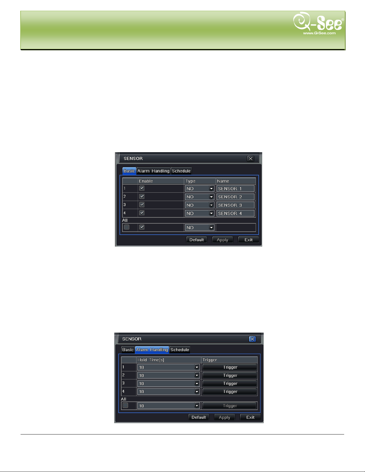
① Basic
Step 1: Enter into system configurationalarm configurationsensorbasic; refer to Fig 4-19:
Fig 4-19 Alarm Configuration-Sensor Basic
Step 2: Enable sensor alarm, set the alarm type accordin g t o t r iggered alarm type. T wo options: NO (normally open)
and NC (normally closed) .
Step 3: User can setup all channels with same parameters, checkmark “all”, then to do relevant setup.
Step 4: Click “default” button to restore default setting; click “apply” button to save the setting; click “exit” button to
exit current interface.
② Alarm Handling
Step 1: Enter into system configurationalarm configurationsensoralarm handling; refer to Fig 4-20:
Fig 4-20 Alarm Configuration-Sensor-Alarm Handling
29 | Page
MAIN MENU SETUP GUIDE QT428 User Manual
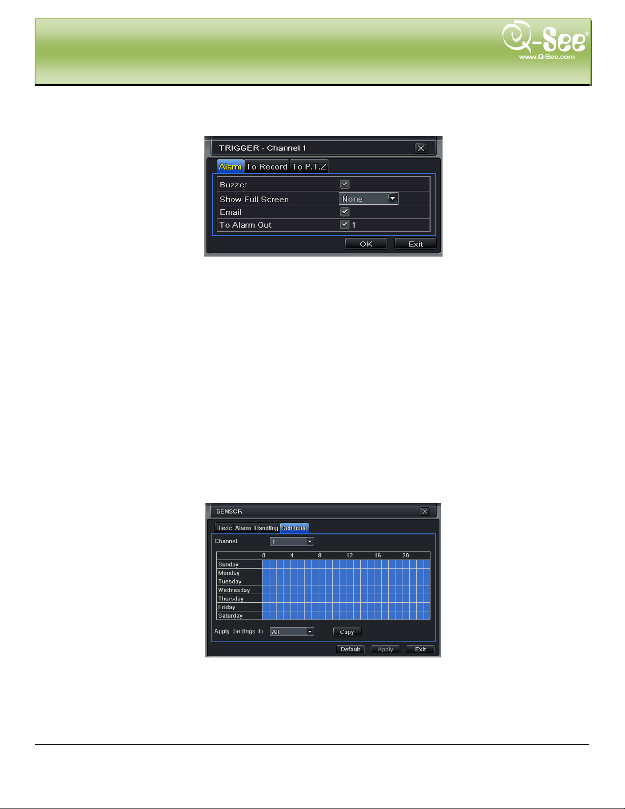
Step 2: Select hold time, click Trigger button, and a dialog box will pop-up shown as Fig 4-21:
Fig 4-21 Alarm Handling-Trigger
Step 3: Checkmark Buzzer, there will be triggered buzzer alarm out;
Full screen alarm: w hen triggered alarm, there will pop up an alarm full screen;
To alarm out: checkmark the channel, there will be triggered alarm out on the designated channel. Click OK
button to save the setting; clic k Exit button to exit the current inter face.
To record: checkmark recoding channels, it will record from the camera when alarm is triggered. Click OK
button to save the setting; clic k Exit button to exit the current inter face.
To P.T.Z: set linked preset and cruise for alarm. User can select any channel or multiple channels as linked
channels. Click OK button to save the setting; click Exit butto n t o exit t he cur rent interface.
Step 4: User can setup all channels with same parameters, checkmark “all”, then to do relevant setup.
Step 5: Click “default” button to restore default setting; click “apply” button to save the setting; click “exit” button to
exit current interface.
③ Schedule
Step 1: Enter into system configurationalarm configurationsensorschedule; refer to Fig 4-22:
Fig 4-22 Sensor-Schedule
Step 2: The setup steps of sensor schedule are similar to schedule; user can refer to 4.4.1 Sche dule for details.
Note: the default schedule of motion detection is all of the time, that is, the color of schedule interface is all
blue.
30 | Page
MAIN MENU SETUP GUIDE QT428 User Manual
4.5.2 Motion
Motion includes two sub me nus: motion and schedule.
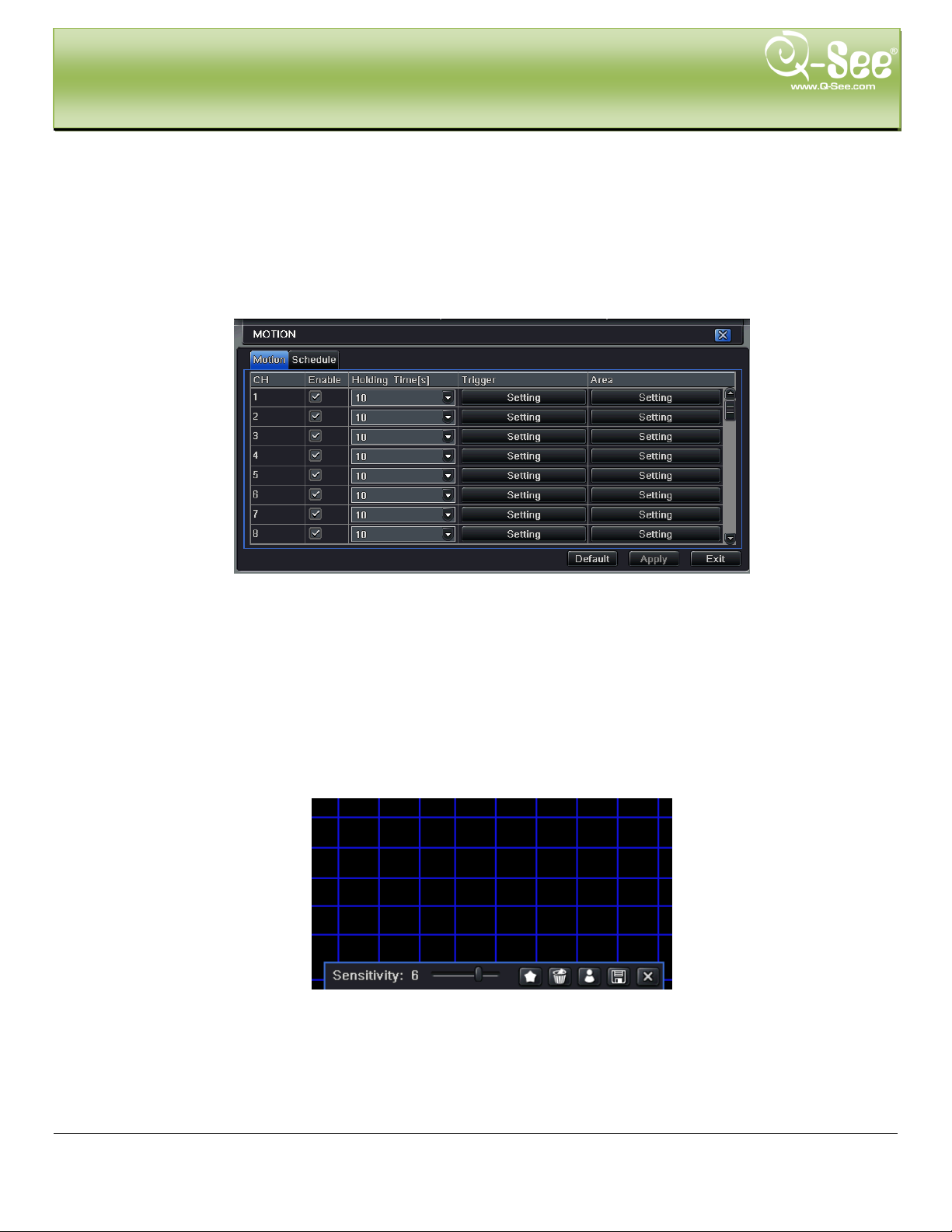
① Motion
Step 1: Enter into system configurationalarm configurationmotion; refer to Fig 4-23:
Fig 4-23 Alarm Configuration-Motion
Step 2: Enable motion a larm, set alar m hold time which means time interval between t wo consecutive motion events.
If there is other motion detected during the interval period which is considered continuous movement; it will be
included in the curre nt f il e, ot her w ise, it will be considered the start of a new m ot ion file. Click Trigger button, a dial og
box will pop-up:
Step 3: The setup steps of motion trigger are similar to alarm handling; user can refer to Chapter 4.5.1 Sensor
alarm handling for more details.
Step 4: Click Area button, a dialog box will pop-up shown as Fig 4-24:
Fig 4-24 Motion-Area
31 | Page
MAIN MENU SETUP GUIDE QT428 User Manual
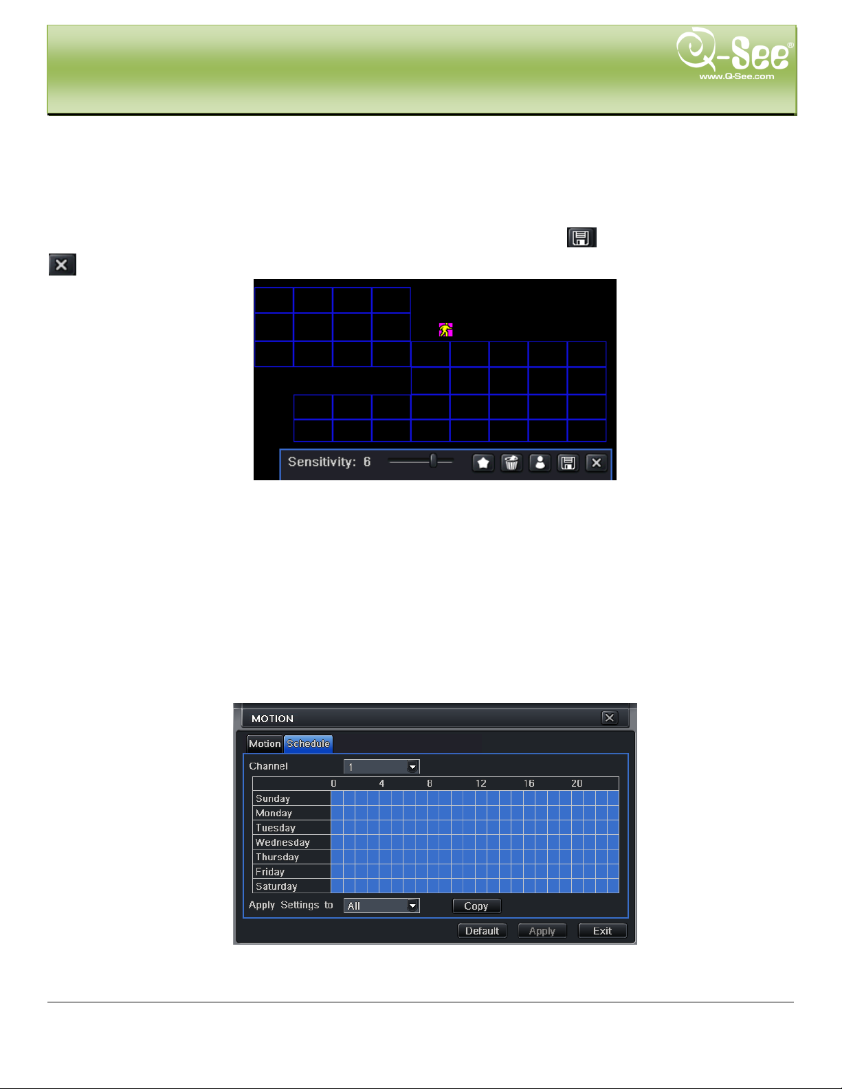
Step 5: In the Area interface, user can drag slide bar to set the sensitivity value (1-8), the default value is 4. The
higher the value the higher sensitivity you get. Since the sensitivity is influenced by color and time (day or night),
user can adjust its value according to the practical conditions; click
icon, set the whole area as detection area;
click
motion area are suitable to current conditions(refer to followi ng picture); Click
Step 6: User can setup all channels with same parameters, checkmark “all”, then to do relevant setup.
Step 7: Click “default” button to restore default setting; click “apply” button to save the setting; click “exit” button to
exit current interface.
② Schedule
Step 1: Enter into system configurationalarm configurationschedule; refer to Fig 4-25:
icon, the set detection area will be cleared; click icon, user can test whether the sensitivity value and
icon, to save the setting; click
icon, exit current interface.
Note: when user drags mouse to set motion detection area, they have to click
current detection area first, and then set the area.
icon to clear
Fig 4-25 Alarm Configuration-Schedule
Step 2: The setup steps of alarm schedule are similar to schedule; user can refer to 4.4.1 S chedule for details.
32 | Page
MAIN MENU SETUP GUIDE QT428 User Manual
4.5.3 Video Loss
Step 1: Enter into system configurationalarm configurationvideo loss; refer to Fig 4-26:
Fig 4-26 Alarm Configuration-Video Loss
Step 2: The setup steps of video loss trigger are fam il iar w it h al arm handling; user can refer to Chapter 4.5.1 Sensor
alarm handling for more details.
Step 3: User can setup all channels with same parameters, checkmark “all”, then to do relevant setup.
Step 4: Click “default” button to restore default setting; click “apply” button to save the setting; click “exit” button to
exit current interface.
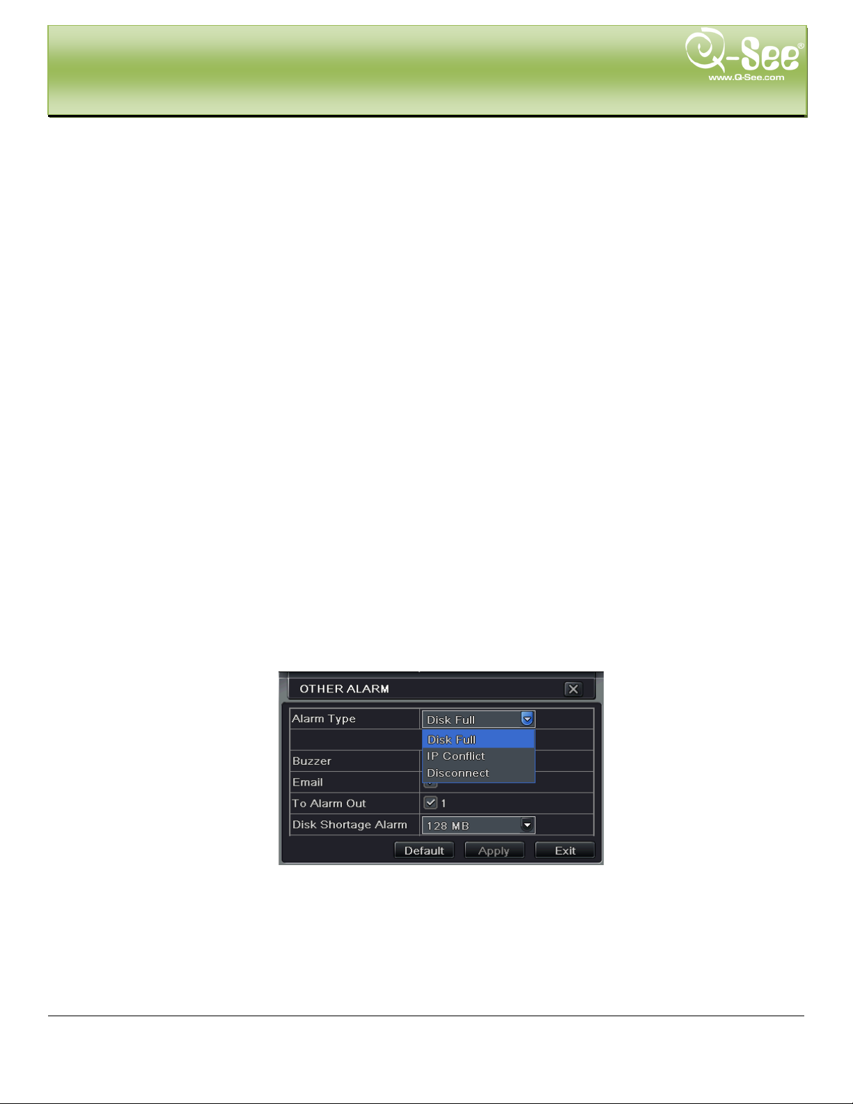
4.5.4 Other Alarm
Fig 4-27 Other Alarm
Step 1: Enter into system configurationother alarm; r ef er t o Fig 4-27:
Step 2:
select a hard disk in the pull down li st box, when the disk capacity is lower than that value, there will
appear some text information on the lower right of the live image.
IP conflict: if there is an IP address conflict within the same network, the device will auto send an email to
users designated mailbox to notify the conflict details.
33 | Page
MAIN MENU SETUP GUIDE QT428 User Manual
Disconnect: if the disconnect happen, the device will auto send disconnection information to users
designated mailbox.
Step 3: Click “default” button to restore default setting; click “apply” button to save the setting; click “exit” button to
exit current interface.
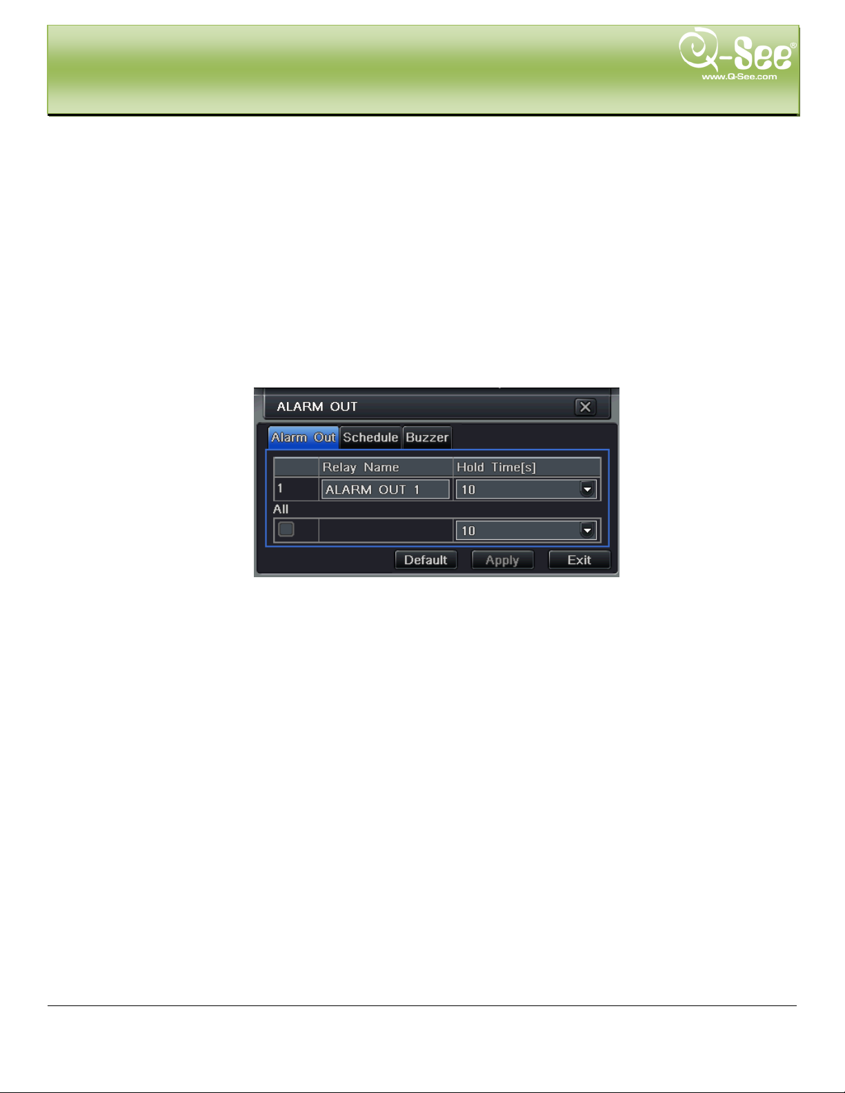
4.5.5 Alarm Out
Alarm out includes three sub menus: alarm out, schedule and buzzer
① Alarm out
Step 1: Enter into system configurationalarm out; refer t o Fig 4-28:
Fig 4-28 System Configuration-Alarm Out
Step 2: In this interface, set relay alarm out name, select hold time which means the interval time between the two
consecutive alarms.
Step 3: User can setup all channels with same parameters, checkmark “all”, then to do relevant setup.
Step 4: Click “default” button to restore default setting; click “apply” button to save the setting; click “exit” button to
exit current interface.
② Schedule
Step 1: Enter into system configurationschedule;
Step 2: The setup steps of alar m out schedule are similar to schedule; user can refer to 4.4.1 Schedule for details.
Note: the default schedule of motion detection is all of the time, that is, the color of schedule interface is all
blue.
③ Buzzer
Step 1: Enter into system configurationbuzzer;
Step 2: Checkmark Buzzer, set buzzer alarm hold time
34 | Page
MAIN MENU SETUP GUIDE QT428 User Manual
4.6 Network Configuration
Network configuration includes two submenus: networ k and network stream.
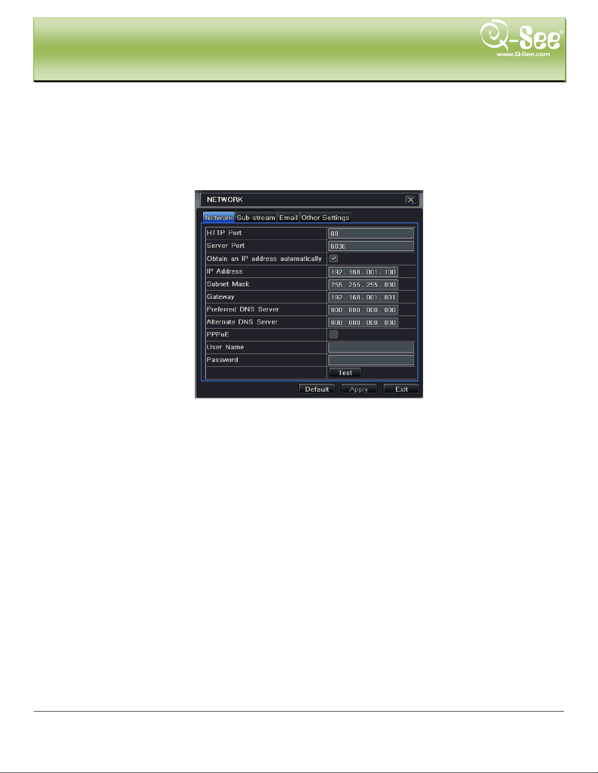
4.6.1 Network
Step 1: Enter into system configurationnetwork conf igurationnetwork; refer t o Fig 4-29:
Fig 4-29 Network Configuration-Network
Step 2: HTTP port: t he default value i s 80. If this value is changed, user needs to add the por t number when ty ping IP
address in IE address blank .i.e. set HTTP port to 82, IP address: http://192.168.0.25, user needs to input this
address: http://192.168.0.25:82 into IE browser. Server port: communication port
Step 3: Checkmark the "Obtain IP address automatically", the device will receive IP address, subnet mask, gateway
IP from the router the DVR is attached to.
Step 4: Enable PPPOE, user can directly connect the DVR to internet via ADSL, then input the user name and
password; click TEST button to test the effectiveness of supplied information. You will need to get the account
information from your internet service provider.
Step 5: Enable DDNS server: user needs to input user name, password and host domain name of the registered
website, click TE ST to test the effectiv eness of information you input.
Step 6: Click “ default” button to restore default setting; click “apply” button to save the setting; click “exit” button to
exit current interface.
35 | Page

Parameter
Meaning
HTTP port
The port number of accessing IE browser. The default
port is 80
Server
port
The port number for data. The default port is 6036
Static IP
IP address
The IP address of the DVR
Subnet
mask
The subnet mask of the serv er
Gateway
The gateway of the router
DNS
server
The address of DNS server
PPPoE
User name
User name of broad band account
Password
Password of broad band account
DDNS server
DDNS
server
Website provided by dynamic domain name supplier.
The optional: myq-see.com, www.dyndns.com
User name
User name to log in to the website of domain name
supplier
Password
Password to log in to the website of domain name
supplier
MAIN MENU SETUP GUIDE QT428 User Manual
Definitions an d descriptions of network configura t ion:
4.6.2 Sub Stream
Step 1: Enter into system configurationnetwork conf igurationsub stream; refer to Fig 4-33:
Fig 4-33 Network Configuration-Sub Stream
Step 2: Select fps, resolution, quality, encode and max bit rate
Step 3: User can setup all channels with same parameters, checkmark “all”, then to do relevant setup.
Step 4: Click “default” button to restore default setting; click “apply” button to save the setting; click “exit” button to
exit current interface.
36 | Page
Parameter
Meaning
FPS
Range from: 1-30
Resolution
Supports CIF and D1
Quality
The quality of the video image. The higher the value is, the clearer
. Six options: lowest , low er, low, medium, higher and highest.
Encode
VBR and CBR
Max bit rate
Range from: 64 Kbps, 128 Kbps , 256 Kbps, 512 Kbps, 768 Kbps,
MAIN MENU SETUP GUIDE QT428 User Manual
Definitions and descriptions of network stream:
the recorded image, and the more hard drive space the recordings
take up
1Mbps, 2 Mbps
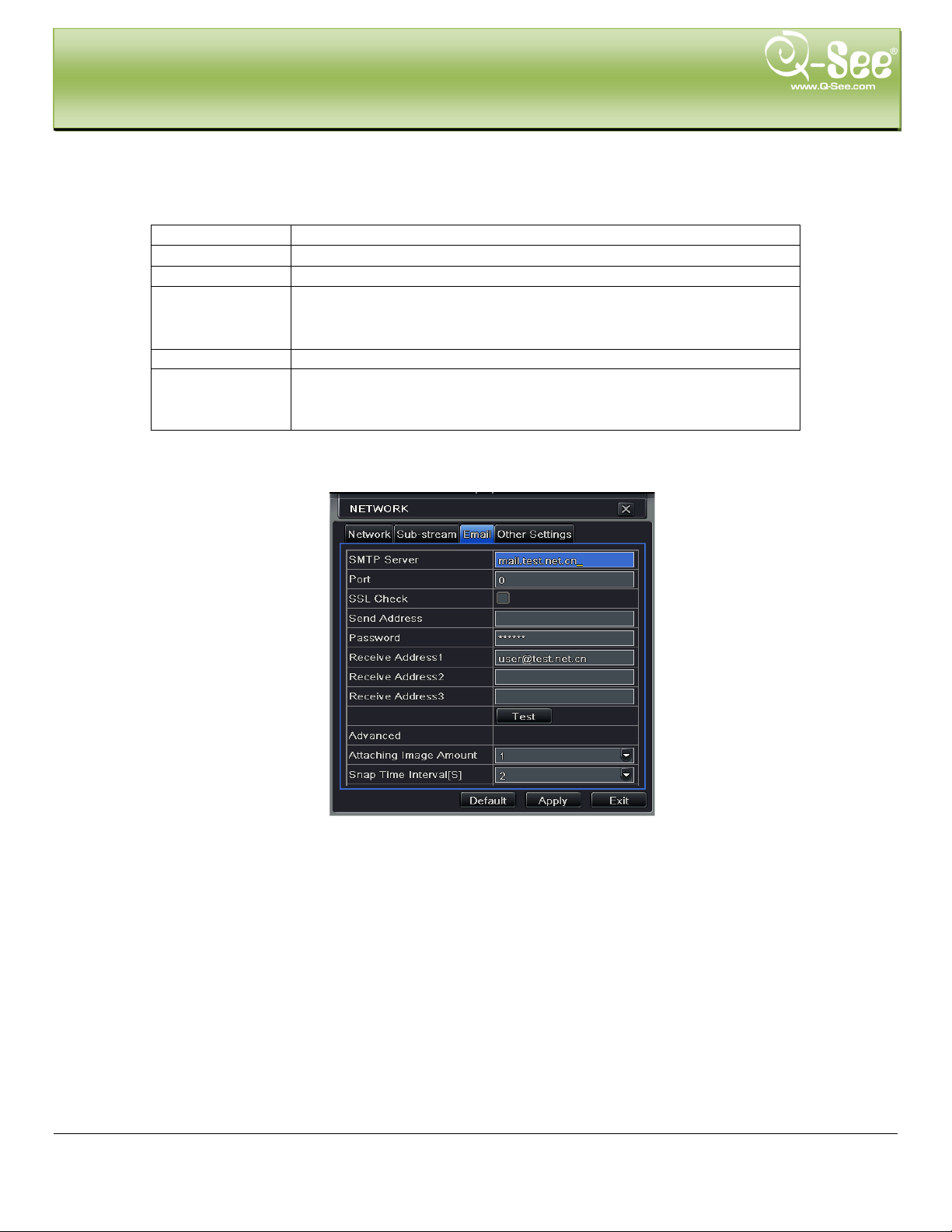
4.6.3 Email
Step1: enter into system configurationnetwork configurationemail; refer to Fig 4-30:
Fig 4-30 network configuration-email
SMTP Server/Port: the name and port number of SMTP server.
Tick off “This ser ver requires a secure c onnection (SSL)”; user can setup mail s ervers (such as Gm ail) according to
actual needs,
Send address/password: sender’s email address/password
Receive address: receiver’s email address. Here user can add at least three mail addresses.
Click TEST button to test the valid of the mailbox.
Attaching image amount: user can attach at least three images by one time.
4.6.4Other settings
Step1: enable DDNS server: user needs to input user nam e, pass word and host domain nam e of the registered
website, click TEST to test the effectively of relevant information.
37 | Page

DDNS server
ebsite provided by dynamic domain name supplier.
The options: myq-see.com and www.dyndns.com
name supplier
the website of domain name
supplier
website.
Update interval
The interval time of checking DVR IP address
MAIN MENU SETUP GUIDE QT428 User Manual
Fig 4-31 network configuration-other settings
STEP2: click “default” button to res ort def ault s etting ; click “apply” button to s ave the s etting ; click “exit” butto n to ex it
current interface.
Note: The domain name server that selected by user is a banding domain name of DVR. User should logon the website
which provided by the serv er supplier to reg i ster a u ser name an d password firstly, and then apply a domain name on line
for the server. After the successful apply, user can access the server from the IE client by inputting that domain name.
This DVR supports myq-see.com and www.dyndns.com DDNS services. We have included instructions for setting up
DDNS access using myq-see.com in Remote Surveillance section.
Definitions and descriptions of network configuration:
DDNS server W
User name User name for log in setup on the website of domain
Password Password for log in to
Host dom ain The domain name user registered at the supplier’s
4.7 User Management Configuration
Step 1: Enter into system configurationuser man agement configuration; refer to Fig 4-34:
Fig 4-34 User Management Configuration
38 | Page

MAIN MENU SETUP GUIDE QT428 User Manual
Step2: Click Add button, a dialog box will pop-up shown as Fig 4-35:
Fig 4-35 Add-General
General: Input user na m e, password; select user ty pe: nor m al or advance.
If you only want the user to be ab le to access the DVR from a specific com puter then put a checkmark in the Bin ding
PC MAC Address option and enter the MA C a ddr ess of the only PC you want the user to be able to access from.
① Authority:
Step 1: Enter into Add userauthority; refer to Fig 4-36:
Fig 4-36 Add User-Authority
Step 2: In the authority interface, assign the def inite operation right for that user.
Step 3: In the user management interface, click Setup button to modify user name, user type and binding PC MAC
address if used.
Step 4: Select the user that you want to delete in the user list box, then click Delete button t o delete this user.
Step 5: Click Change passw or d but t on t o m odify the password; click Exit but ton to exit the current interface.
39 | Page

Parameter
Meaning
Address
The address of the PTZ device
Baud Rate
Baud rate of the PTZ device. Range form: 110, 300,
1 15200, 230400, 460800, 21600.
Protocol
Communication protocol of the PTZ device. Supported
Protocols are: NULL, PELCOP, PELCOD, LILIN,
R, VIDO, DSCP, VISCA,
SAMSUNG, RM110, HY
MAIN MENU SETUP GUIDE QT428 User Manual
4.8 P.T.Z configuration
P.T.Z configuration inclu des two submenus: serial port and advance
Serial Port
Step 1: Enter into system configurationP.T.Z configurationserial port; refer to Fig 4-37:
Fig 4-37 P.T.Z Configuration-Serial Port
Step 2: Checkmark Enable, setup the value of address, baud rate and protocol according to the settings of the PTZ
speed dome.
Step 3: User can setup all channels with same parameters, checkmark “all”, then to do relevant setup.
Step 4: Click “default” button to restore default setting; click “apply” button to save the setting; click “exit” button to
exit current interface.
Definitions and descriptions of PTZ:
600, 1200, 2400, 4800, 9600, 19200, 34800, 57600,
MINKING, NEON, STA
40 | Page

MAIN MENU SETUP GUIDE QT428 User Manual
Advance
Step 1: Enter into system configuration P.T.Z configurationadvance; refer to Fig 4-38:
Fig 4-38 P.T.Z Configuration-Advance
Step 2: In the Advance interface, click preset “Setting” button, a dialog box will pop-up shown as Fig 4-39:
Fig 4-39 Advance-Preset Setting
41 | Page

MAIN MENU SETUP GUIDE QT428 User Manual
a. In the preset set interface, click Setting button, a dialog will pop-up shown as Fig 4-40:
Fig 4-40 Preset Set-Setting
b. User can control the dome rotating up, up l eft, down, right down, l eft , left down, right and up right and
stop rotating; adjust t he r otate speed and the value of zoom, focus and iris of the dome;
c. Select the serial number of the preset point, set the preset name. Click Save button to save the settings,
click
d. In the preset interface, click OK button to save the s et t ing; c l ick Exit button to exit current interf ace.
Step 3: In the Advance interface, click cruise “Setting” button, a dialog box will pop-up shown as Fig 4-41:
icon to hide the tool bar, right-key can display it ; click icon to exit the current interface.
Fig 4-41 Cruise Set
a. Click Add button to add cruise line in the list box (max 8 cruise lines can be added); select a cruise line,
click Setup button, a dialog box will pop-up shown as Fig 4-42:
42 | Page

MAIN MENU SETUP GUIDE QT428 User Manual
Fig 4-42 Cruise Set-Modify Cruise Line
b. Click Add icon to set the speed and time of preset poi nt ; select a pr eset point, click Delete icon
to delete that preset point; clic k M odify icon to modify the setting of a preset point. User can
click icons to adjust the position of preset point. Click Preview button to pr eview the cruise
line, click OK butt on to save the setting, click Exit b ut ton to exit current interface.
c. Select a preset point in the cruise line list box, click Delete button to delete that cruise line; click Clear all
button to clear all cruise li nes from the list box; click OK but t on t o save the setting; click Exit but t on t o exit
current interface.
Step4: In the Advance interface, click track “Set” button, a dialog box will pop-up as Fig 4-43:
Fig 4-43 Track Set
a. User can control the do me rot ating up, up left, down, right down, left, left down, right and up right and stop
rotating; adjust the rotate speed and the value of zoom, focus and iris of the dome; click Start Record
button to record the moving track of PTZ, click this button again to stop recording; click Start track button
to play recorded track, click this button again to stop play.
b. Click
Step 5: In the Advance interface, click “default” button to restore default setting; click “apply” button to save the
setting; click “exit” button to ex it cur r ent interface.
icon to hide the tool bar , right-key can display it; click icon to exit the current interface.
43 | Page

MAIN MENU SETUP GUIDE QT428 User Manual
4.9 Advanced
Advanced configuration includes two submenus: reset and import/export.
4.9.1 Reset
Reset all settings the device will reboot.
4.9.2 Import/Export
User can export the data files into PC as backup function, and then import specified data files from PC to device.
44 | Page

RECORD, SEARCH, PLAYBACK & BACKUP QT428 User Manual
5. RECORD, SEARCH, PL AYBACK AND BACKUP
Search configuration includes three submenus: time search, event search and file man ager.
5.1 Time Search
Step 1: Enter into Search configurationtime search; refer to Fig 5-1:
Fig 5-1 Search Configuration Time Search
Step 2: Select channel, screen display mode, the highlighted dates on the calendar means the days have
recorded data.
Step 3: Select a date, press Search button, cl ick the time gr id to set the play start time or input play time manually .
The selected time will match the blue gri d.
Note: the vertical column represents the C han ne l num ber. The horizontal col umn represents hour s of the
day.
Step 4: Click Play
operations:
Note: when the monitor reso lution is VGA 800*600, the time search interface will show a hide button,
click this button, the whol e i nter f ace will be expanded.
button to playback record; click the relevant buttons on the screen to do various
Playback Buttons
45 | Page
RECORD, SEARCH, PLAYBACK & BACKUP QT428 User Manual
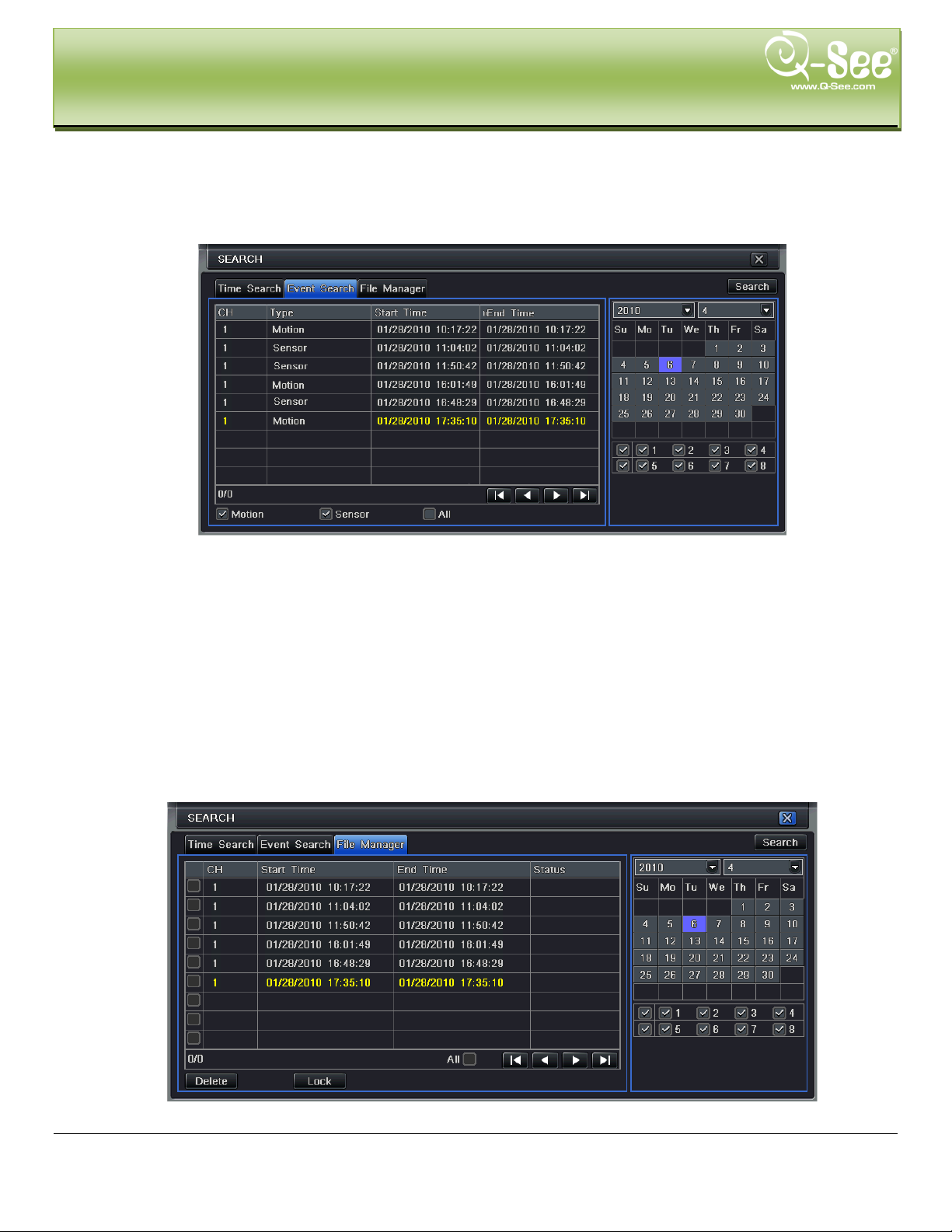
5.2 Event Search
Step 1: Enter into Search configurationevent searc h; r efer t o Fig 5-2:
Fig 5-2 Search Configuration-Event Search
Step 2: Click Search button, the searched event information will be displayed in the event list box. Select date,
channel, checkmark Motion, Sensor or Al l accordingly.
Step 3: Double click the record file you would like to playback.
Note: when the monitor resolution is VGA 800*600, the event search interface will display a hide button,
click this button, the whol e i nter f ace will be expanded.
5.3 File Manager
Step 1: Enter into Search configurationfile manager; r efer t o Fig 5-3:
Fig 5-3 Search Configuration-File Manager
46 | Page
RECORD, SEARCH, PLAYBACK & BACKUP QT428 User Manual
Step 2: Click Search button, the searched files will be display ed in t he file l ist b ox, user can sel ect dat e, c hann els
accordingly.
① Lock: check a file, click Lock button to lock this file, after that, that file will not be deleted or covered
(unless you format the hard dr iv e).
② Unlock: check a locked file, click Loc k b ut t on t o unlock this file
③ Delete: check an unlocked file, clic k Delete button to delete this file.
Step 3: Checkmark “All” button; user can loc k/unlock or delete all files in the file manager column.
Step 4: Double click an unlocked item to playba ck.
Note: when the monitor resolution is VGA 800*600, the file manager interface will display a hide button.
Click this button to expand the interface.
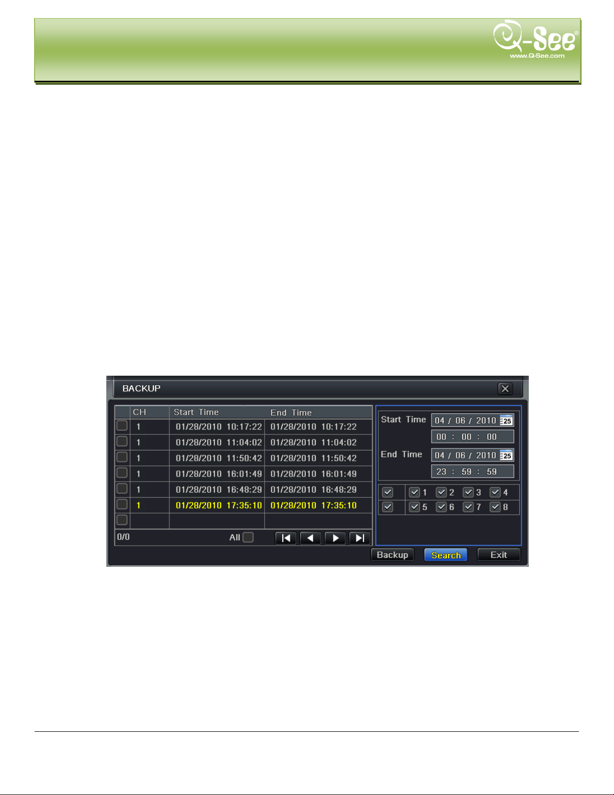
5.4 Backup
This unit supports backup to USB Flash, USB hard dr ive and USB DVD burner through the US B por t on the front
panel. You can also backup via IE browser over the Internet. Refer to 7.6.2 Remote Backup.
Step 1: Enter into backup configuration; refer to Fig 5-4:
Fig 5-4 Backup Configuration
Step 2: Set the start & end time, select channels, click Search button, the searched data will be displayed in the
data backup list box
47 | Page

RECORD, SEARCH, PLAYBACK & BACKUP QT428 User Manual
Step 3: Check a data file or checkmark “All” to select all data files , click Backup button, a dialog box will pop-up
shown as Fig 5-5:
Fig 5-5 Backup Information
Step 4: In the backup information interface, you can check the relev ant information of backup files, storage ty pe,
save file type, etc. Once click Apply button to start backup.
To play back the files plug the USB device to a PC and browse the device, you will see 2 folders, one
VideoPlay, and another containing video files. Open the VideoPlay folder and run Videoplay.exe, click on
open path, and point to folder with video files.
Note: when the monitor resolution is VGA 800*600, the file manager interface will display a hide button,
click this button, the whol e i nter f ace will be expanded.
48 | Page
DVR MANAGEME NT QT428 User Manual
6. DVR MANAGEMENT
6.1 Checking System Information
Check system informat ion incl udes five submenus: system, ev ent , log, net w ork and online users.
6.1.1 System Information
In this interface, user can check the hardware version, MCU version, kernel version, device ID, etc. refer to
Fig 6-1:
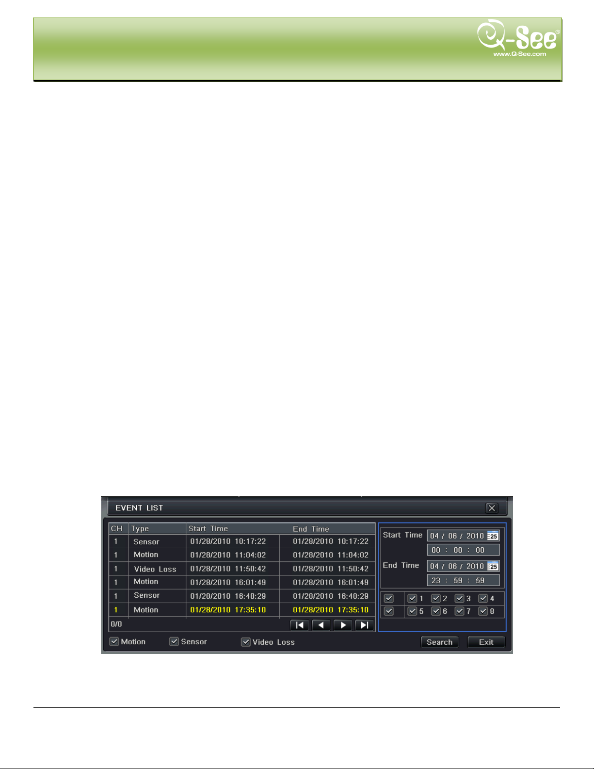
6.1.2 Event Information
In this interface, user can check recorded events according to s elected date; refer to Fig 6-2:
Fig 6-1 System Information
Fig 6-2 Event Information
49 | Page
DVR MANAGEME NT QT428 User Manual
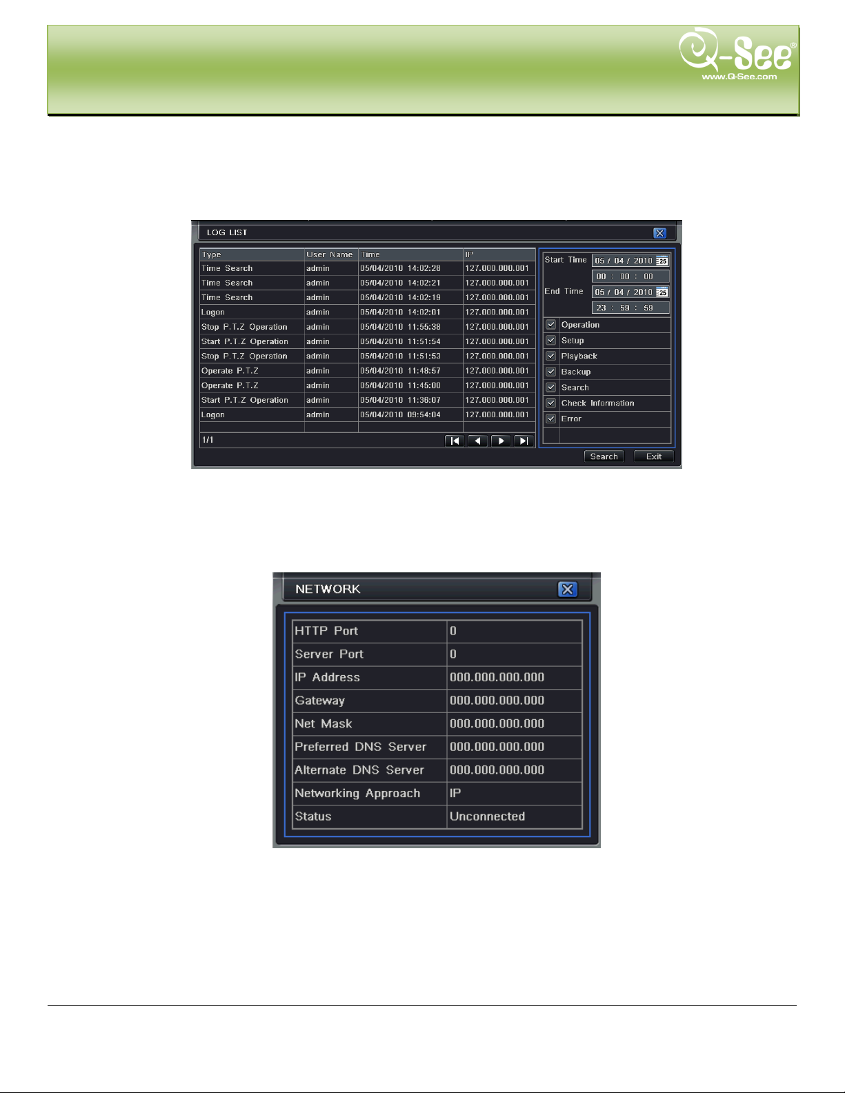
6.1.3 Log Information
In this interface, user can check relevant log information according to selected date; refer to Fig 6-3:
6.1.4 Network information
In this interface, user can check relevant parameter s of netw ork; refer to Fig 6-4:
Fig 6-3 Log Information
Fig 6-4 Network Information
50 | Page
DVR MANAGEME NT QT428 User Manual
6.1.5 Online Information
In this interface, user can check the details of the current connection of online users; refer to Fig 6-5:
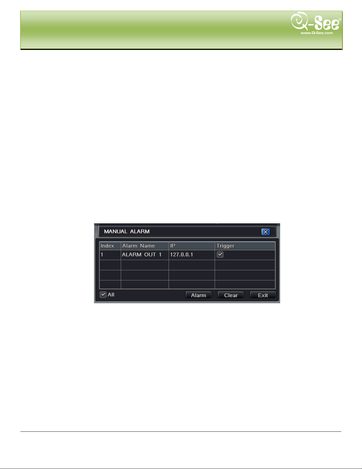
6.1.6 Manual Alarm
In this interface, user can check the relevant parameters of manual alarm; refer to Fig 6-6:
6.1.7 Disk Manager
Step 1: Enter into disk manager interface; refer to Fig 6-7:
Fig 6-5 Online Information
Fig 6-6 Manual Alarm
Fig 6-7 Disk Manager
51 | Page

DVR MANAGEME NT QT428 User Manual
Note: you need to format the hard disk before recording. The screen will show the size of the drive,
amount of free space, and percentage of used space at the bottom of the screen.
Step 2: Click Refresh button to refresh the disk information of the list box; set the property of the disk then
click Apply button to save the setting
Step 3: Select the hard disk, click Format button to start format.
Note: all recorded files in the hard disk will be lost after formatted.
6.1.8 Upgrade
At present, it only supports US B update. Get the firmware from Q-See when there is a new firmw ar e version,
and make sure it is the correct one for the DVR. User can check the USB information in Disk manager.
6.1.9 Logoff
Click Log off icon, a log off dialogue box will po pup, c lick O K button, the d evice will lo g off. If user want s to log
in again, click
icon to enter user name and password to login again.
52 | Page

REMOTE SURVEILLANCE QT428 User Manual
7. REMOTE SURVEILLANCE
7.1 Network Access
Accessing the DVR from a comp uter at t ache d to t he same router: If y ou are only going t o access the D VR fro m a
computer that is attached to the same router as the DVR you only need to setup the information in the
NETWORK settings using either the DHCP option or assigning a static IP following the instructions below. Since
you are just going from one location to another on the same network port forwarding and knowing the public IP
address are not necessary. You would just access the DVR by entering the IP address of the DVR from the
NETWORK setup into the Internet Explorer browser window. After you setup the NETWORK settings using
DHCP or Static IP instr uctions skip down to the section: To access the DVR through Internet Explorer.
7.2 Setting Up Remote Access
There are 4 ways you can setup t he D VR to be accessed remotely; DH C P, Static IP, PPPOE, and DDNS.
DHCP: If your router is setup for DHCP, and most of them are by default, you can have the router assign an IP
address to the DVR. To do this go to the Main Menu and select the System icon (Red box in Fig 7-1), then select
the Network icon (Re d box in Fig 7-2), this will display the NETWORK screen shown in Fig 7-3. Put a checkmark
in the box at the end of the “Obtain an IP address automatically” line (Red box in Fig 7-3) and then click the
TEST button (Green box in Fig 7-3). After you get the OK message in the lower left hand corner of the screen
you click the Apply button to save the IP address. To find out what IP address was assigned you need to go to
the Information icon (Green box in Fig 7-1). After the router has assigned the DVR an IP addr ess it is a go od idea
to write down the address from the information section and then type the address into the IP address line and
then remove the checkmark from the box above the line. This is the IP address you will forward ports 80 and
6036 to on the router so you can access the DVR from remote computers.
Fig 7-1 Main Menu Fig 7-2 System
53 | Page

REMOTE SURVEILLANCE QT428 User Manual
Fig 7-3 DHCP
Static IP: You will need to setup the network settings on the DVR to match the settings of the router that you
attach the DVR to. To get the router settings you would go to the run option on a computer attac hed to the same
router as the DVR and type cmd and hit OK to bring up a command prompt (Fig 7-4), then type ipconfig at the
prompt (RED arrow on Fig 7-4) to access the router settings. Write d own the g ateway and subnet mas k number s
(GREEN arrows on (Fig 7-4) so you can copy them into the network settings on the DVR (GREEN boxes on Fig
7-5). Go to the Main Menu and select the Setup option (Red box in Fig 7-1), then select the Network icon (Red
box in Fig 7-2), to get to the NETWORK screen shown in Fig 7-5.
Fig 7-4 ipconfig
54 | Page

REMOTE SURVEILLANCE QT428 User Manual
Fig 7-5 Static IP
For the DVRs IP a ddress you would enter the same first 3 set s of numbers as the gat eway and select a fourt h
set of numbers that is different then any other device attached to the same router. If the IP address of your
computer in the ipconfig (BLUE arrow in Fig 7-4) was a single or two digit numb er you should be ok with any
three digit number, if the computer IP address ends with a number in the 100s then you should go with a 200
number (Blue arrow in Fig 7-5). After you enter the numbers click the test button (Red box in Fig 7-5), when
you get the OK message in the lower left corner of the screen cl ic k o n t he Apply button to save the setting.
PPPOE: If you are going to attach the DVR directly to a DSL or Cable modem instead of a router you will
need to select the PPPOE option in the NETWORK options. To do this go to the Main Menu and select the
System icon (Red box in Fig 7-1), then select the Network icon (Red box in Fig 7-2), this will display the
NETWORK screen shown in Fig 7-6. Put a checkmark in the PPPOE option box (Red box in Fig 7 -6) and
enter your internet account User Name and Password in the boxes. You will need to contact your internet
service provider to get the User name and Password you need to enter into these boxes. After you enter the
information into the boxes click on the Test button (Green box in Fig 7-6), after you get the OK message in
the lower left of the scre en click on the Apply button to save the information.
55 | Page

REMOTE SURVEILLANCE QT428 User Manual
Fig 7-6 PPPoE
DDNS: You can access the DVR through a static or dynamic IP address; however a dynamic address can
change from time to time. How often depends on your service provider. When it changes you need to go to a
website such as www.myipaddress.com from a computer attached to the same router as the DVR to find out
what the new IP address is. There are two solutions to this problem. One would be to get a static IP address
from your service provider so that you do not have to be concerned with the address changing. Another solution
would to use a dynamic domain name service to get a domain name that can be linked to your dynamic IP
address. We suggest myq-see.com or www.dyndns.com since the DVR is setup to accept account information
from these two domain name s er vices.
NOTE: Before you setup DDNS you must first set up Port Forwarding as directed in Section 7.3 PORT
FORWARDING
56 | Page

REMOTE SURVEILLANCE QT428 User Manual
To setup the DVR for access through a dynamic domain name you go to the Main Menu and select the System
icon (Red box in Fig 7-1), then select the Network icon (Red box in Fig 7-2), this will display the NETWORK
screen shown in Fig 7-7. Put a checkmark in the DDNS option (Red box in Fig 7-7). Select the service you are
using from the drop d ow n menu under the checkmark box and enter the account information you registered with
the domain name service. Click the Test button under the boxes where you entered the account inform at ion and
after you get the OK message in the lower left hand corner of the screen click on the Apply button . You will then
be able to access the D VR r emote ly by ent erin g the do main na me int o a br ow ser w indow on a re mote com puter.
This DVR supports DDNS provided by myq-see.com and www.dyndns.com. Instructions for setting up DDNS
through mwq-see.com is prov ided below.
Fig 7-7 DDNS
57 | Page

REMOTE SURVEILLANCE QT428 User Manual
Setting up MYQ-SEE DDNS:
NOTE: Before you setup DDNS you must first set up Port Forwarding as directed in Section 7.3 PORT
FORWARDING. Once you have enabled Port Forwarding, you can configure your DDNS information by
following these step s:
a. Using a computer that is connected to the same network as your Q-See DVR, use your IE Browser to go to
http://myq-see.com.
b. Click on the New User? Link at the bottom of the page (http://myq-see.com/reg.asp).
c. Complete the registration process by following the on-screen directions and click the [Submit] button at the
bottom of your screen (Fig 7-8).
Fig 7-8 Registration
58 | Page

REMOTE SURVEILLANCE QT428 User Manual
d. The next screen will ask you to create a domain name. Domain names must start with an (a-z) or (0-9) and
cannot contain a hyphen. Once you choose your domain name, click on the [Request Domain] button.
This will generate a confirmation screen which tells you if your Domain name is available and list an IP
address (Fig 7-9). Verify that this is your current IP Address by going to www.myipaddress.com and
checking that it is the same address listed in your confirmation scr een (Fig 7-9).
Fig 7-9 Domain Name
59 | Page

SETUP
REMOTE SURVEILLANCE QT428 User Manual
e. Once you have completed steps a-d, go to the Main Menu and select the Setup icon (Red box in Fig 7-10),
then select the Network icon (Red box in Fig 7-11), this will display the NETWORK screen shown in Fig 7-12.
Setup
f. Put a checkmark in the DDNS option (Red Box in Fig 7-12), then select the MYQ-SEE option from the drop
down box, and enter the account information you setup on the myq-see.com site into the boxes under the
drop down box (see Fig 7-13).
Fig 7-10 Main Menu Fig 7-11 Setup
Fig 7-12 DDNS
60 | Page

REMOTE SURVEILLANCE QT428 User Manual
g. After you enter the information click on the Test button (Green box in Fig 7-13) and wait until you see the OK
message in the bottom left hand corner of the screen.
h. Click the [APPLY] button and then the [EXIT] button at the bottom of the NETWORK screen and your DDNS
setup is complete.
Fig 7-13 myq-see
DDNS Server: Select MYQ-SEE from the drop down menu.
Username: The email address you entered on the m yq-see site.
Password: Enter the password you setup on the myq-see site.
Host Domain: Enter the account name you setup on the myq-see site.
61 | Page

REMOTE SURVEILLANCE QT428 User Manual
7.3 Port Forwarding
To access the DVR from a remote computer you need to forward ports 80 and 6036 from the
router the DVR is attached to, to the IP address of the DVR.
1. Connect your DVR to the Rout er and power on DV R
2. Configure your DVR and Set up port forwarding on your router
a. Go to www.portforward.com/qsee
b. Choose your DVR or Series (QT, QSDT, QR, QS etc) from the list provided
c. Select the make and model of your router from the list
62 | Page

REMOTE SURVEILLANCE QT428 User Manual
d. Click on the ‘Click here to ski p t hi s advertisement…’ link in the upper right corner of the
screen.
Notice: When you go to the www.portforward.com website you will see an ad for a software program that will setup
port forwarding for you. You do not need to buy this software. A b ov e the ad t here is a link to skip the ad, if you click on
the link it will take you to the instructions which are free. You can purchase the software if you want to, but you do not
need to pay to get the port forwarding instructions.
e. Follow the instruction on the website (Th e top set of instructions are done on the DVR. The
bottom set of instructions are done on the router)
f. Verify the ports are op en and traffic is allowed
a. Go to www.canyouseeme.org
b. Type the port number that your DVR requires in the box.(See picture)
The default ports are 80 and 6036.
63 | Page

REMOTE SURVEILLANCE QT428 User Manual
c. Verify that the port(s) is open.
i. If the port is open, you will see the following message:”Success. I can see your
service…”
ii. Go to the section below: To access the DVR through Internet Explorer
iii. Otherwise, if the ports are not open, you will g et t he follow ing messag e: “ Error: I could
not see your service on 64.206.234.34 on port (80) - Reason:
you get this error, call your Internet Ser vice Provider (ISP) and ask them to unblock
those ports for you.
64 | Page
Connection refused”. If
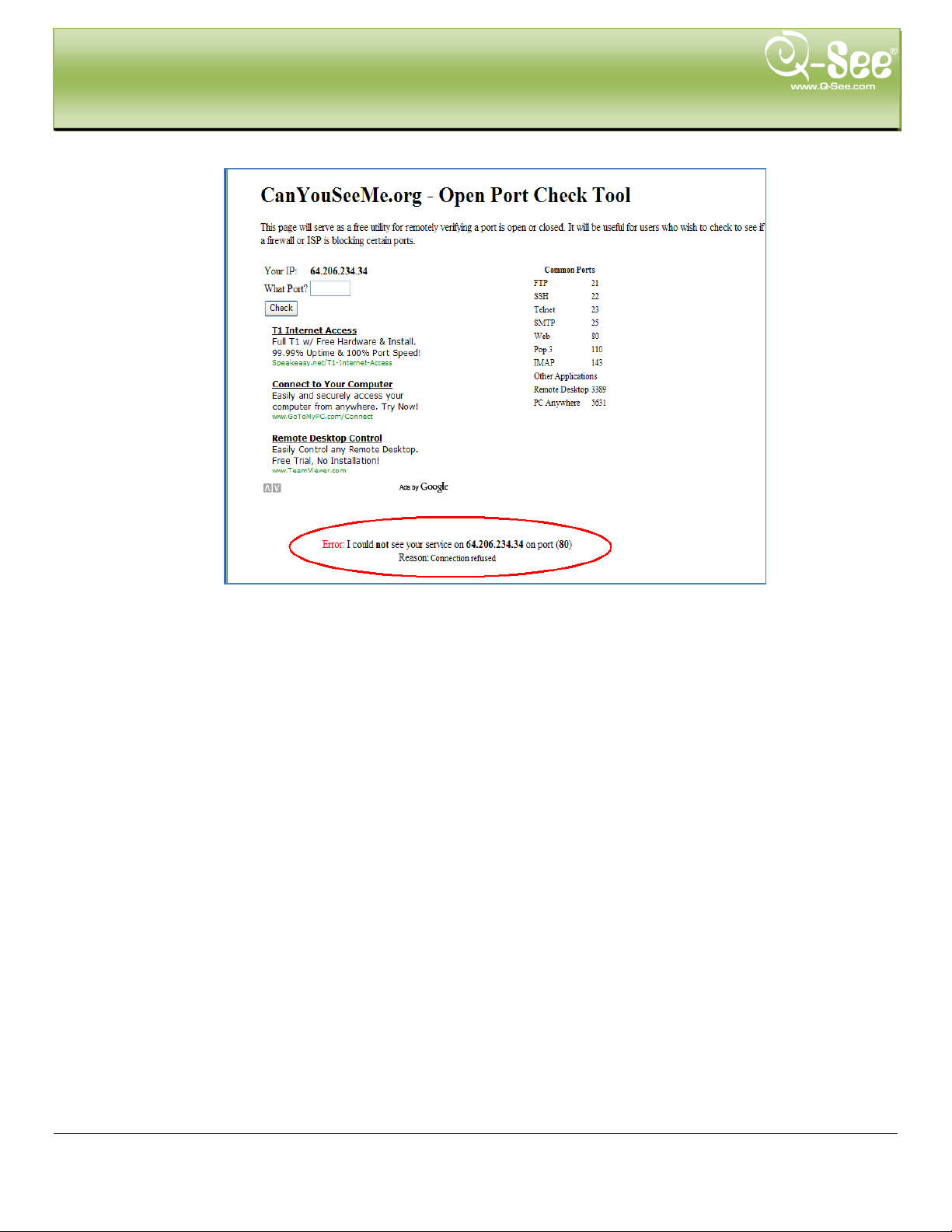
REMOTE SURVEILLANCE QT428 User Manual
iv. After your I SP unblocks those ports for you, repeat steps i and ii.
When you access the DVR from a remote computer you also need to use a different address in the
Internet Explorer browser window. Instead of entering the IP ad dress of the D VR yo u need to enter the
public IP address of the router the DVR is attached to. You can get this address by going
to www.myipaddress.com from a computer that is attache d to the same router as the DVR. This website
will display the box in Pic 8 below that shows the IP address you need to use. It will be in the space where
the below example shows 76.254.183.54.
Pic 8
To access the DVR through Internet Explorer: once you have setup the network settings on the DVR to match the settings of
your router and forwarded the ports needed by the DVR (for remote access over the internet), you need to modify your browser
controls. You need to allow Pop-ups. To do so go to the Internet Explorer tool bar and select the "tools" option (RED box in Pic 9),
then select the "Pop up Blocker" option and select "Turn Off Pop-up Blocker” (BLUE arrows in Pic 9). You will also need to enable
Active X controls. To do so go to the Internet Ex plorer t ool bar and sele ct the "tools" option, then "I nterne t Optio ns"(GR EEN arrow in
Pic 9).
65 | Page
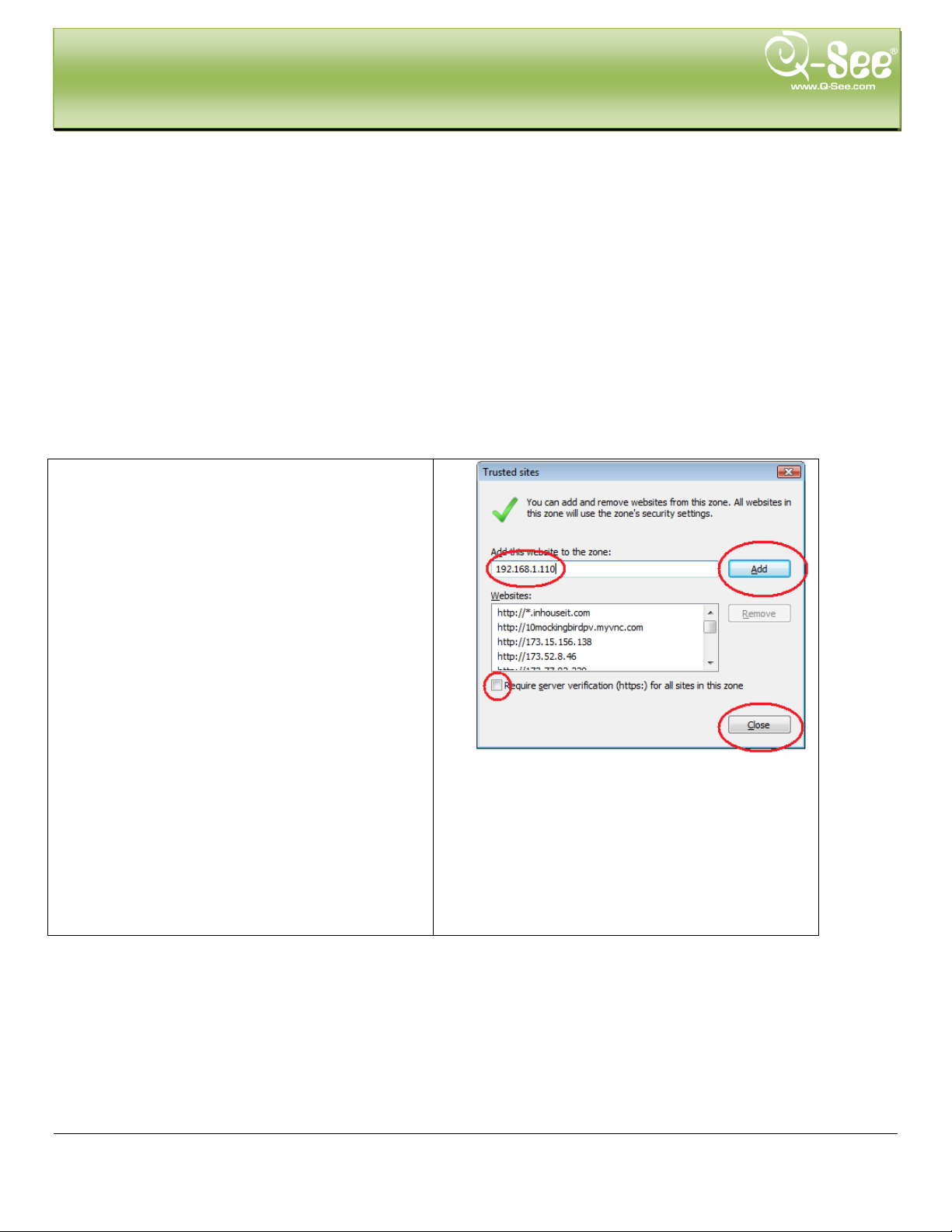
Sites button.
REMOTE SURVEILLANCE QT428 User Manual
Pic 9
Pic 10
Click on Sec urit y Tab. Click on Trusted Sites . Click on
Uncheck the box for Require Server verification. Put
the IP addess of the DVR or WAN IP address in the
Add this websites to the zone box and click on Add
button. Click on Close
66 | Page
Pic 11
.

change the setting for this zone?’ Click OK. Click
Apply. Click OK. Close Internet Explorer.
REMOTE SURVEILLANCE QT428 User Manual
Click on Custom Level
Pic 12
On “Reset to” pull down menu, select “LOW” then
click on “RESET” button.
Click ‘Yes’ when asked: ‘Are you sure you want to
Pic 13
If you get a error mes sage that says the program c annot load because the p ublisher is unknown or th e program is
unsigned, go to internet explorer, tools, internet options (refer to Pic 9), then go to the “Advanced” tab (RED box in Pic
14), this will open the window in Pic 15, scrol l down to “Sec urity”, and s elect the opt ions to “A llow software to r un or
install even if the signature is invalid”, and “Allow Active Content to Run Files on My Computer” (RED box in Pic 15).
Pic 14 Pic 15
67 | Page

REMOTE SURVEILLANCE QT428 User Manual
To connect to the DVR from the remote computer you would then open an Internet Explorer browser window and
enter the internet IP of your router that you got by going to www.myipaddress.com (you have to do this from a PC that
connect to same Router as your DVR).
Notice: If you cannot use HTTP port 80 or 6036 because the port is being used by another program, or it is
being blocked by your s ervice provider, you can use another port in the same range. If you do so then you
need to forward the IP address of the router to the other port, change the port in the DVR NETWORK settings,
and you need to add the port number after the IP address. For example, if you set the HTTP port as 82, you
need to enter the IP address as 192. 168.0.25:82. After yo u have forwarded the po rts you can verify that th e
ports are open by going to canyouseeme.org from a computer that is attached to the sa me router as the DVR.
Once you able to login, you will get the login screen, by default the login and password are admin and
123456 .
Notice: If you still have problems connecting remotely: Anti-virus programs could also block the ActiveX control,
if you still have a problem try clos ing them. Other plug-ins could also block it. Close firewalls in Windows
and in the router if applicable. If you run Windows Vista or Windows 7, you will need to disable User
Account (UAC).Follow this link for inst ructions:
http://www.howtogeek.com/howto/windows-vista/disable-user-account-control-uac-the-easy-way-on-windows-vista/
If you have a router plugged into another router, for example, if you have the DVR attached
to a router wh ich is attached t o DSL or Cable route r, you may need to forwa rd port 80 and 6036
(or whatever ports you are using) on the DSL or Cabl e router to the IP address of the router
that the DVR is attached to, so that router ca n t hen fo rwa r d th e por t t o th e DV R. Pl ea se r ef e r
to the PORT FORWARDING section above on how to get instructions on how to forward the
port on the other router.
68 | Page

REMOTE SURVEILLANCE QT428 User Manual
7.5 Using the Remote Access Software
Once you have setup Internet Explorer you can access the DVR through a browser window. If you are accessing the
DVR over the network you would enter t he IP addres s of the DV R into the address bar. If you are accessing the DVR
from a remote computer you will enter the public IP address of the router. This is the address you get by going
to www.myipaddress from a computer attached to the same router as the DVR. When you connect to the DVR you
will be prompted to download a webcam program to access the cameras. When the download is complete you will
see a login window to access t he D VR. Af t er you put in the password informat i on you will see the following screen:
Symbol and Function Definitions:
1. Channel Indicator 2. Screen Display Mode 3. Volume
4. Snapping Picture 5.
7. Master/Su bs tream Status 8. Color Adjustment 9. PTZ Control
10. Record Manually to PC 11. Two way talk
Fig 7-21 Remote Live Preview Interface
Start Record 6. Playback
69 | Page

REMOTE SURVEILLANCE QT428 User Manual
Note: click button to record man ua lly and the recorded file will be saved on your PC hard drive.
Screen display mode:
Click the
icon beside the screen display mode, channel select dialog will ap pear as shown below:
Fig 7-22 Channel Select Dialog
User can checkmark chan nels form 1-ch to 16-ch at random to display the live pictures. Then click OK button to
confirm the setting.
Snap Pictures
1. Click “Snap” icon, select the number of pictures, refer to Fig 7-23:
Fig 7-23 Single Snap
2. User can take multiple pictures , select the picture number from snap count pull down list box, such as 3,
checkmark “Title” and “T i me”, it w ill show capture title and t ime on t he s nap pi ctur es simultaneously. Refer to
Fig 7-24:
Fig 7-24 Multi-Picture Snap
3. Click “Browse” to set saving path; Click “Save” to save pictures to HDD on the computer; click Exit button to
exit current interface.
70 | Page

Drag the scroll bar to adj ust the br ightness of c hann el
Drag the scroll bar to adjust t he cont r as t of ch annel
Drag the scroll bar to adjust t he sat ur ation of channel
Drag the scroll bar to adjust t he hue of c hannel
Click this button to recover the default value of
brightness, contrast, s at ur at ion and hue.
Save the adjustment
the dome to the left. move the dome to the right. store the dome rotating.
Drag the scroll bar to adjust rotating speed of the dome.
button near 'Iris' button to decrease light of the dome image.
Click button near 'Zoom' button to zoom out on the picture of this camera.
near 'Focus' button to focus closer.
Go to the Preset
Select and do auto cruise
Track
Auto scan
REMOTE SURVEILLANCE QT428 User Manual
Color Adjustment:
Drag the slide bar to adjust Brightness, Contrast, Hue, and Saturation. Click Default to reset them to original
value.
BUTTON DESCRIPTION
PTZ Control
Connect the PTZ speed dome to the device via RS485. Ensure the protocol of the speed dome is supported by
the device and set the relative parameters manually. User can control the dome up, down, right, left or stop
rotating in Contro l Ce nt er, adjust rotation speed, Iris and zoo m, foc us on t he dome, and set the presets , etc.
Buttons definition:
BUTTON DESCRIPTION
move the dome up. m ove the dom e up and left. move the dome up and right move
dome down.
'Iris' button. Click
'Zoom' button. Click
'Focus' button. C lick
move the dom e left and down. move t he dome right and do wn. move
button near 'Iris' button to increase light of the dome image. Click
button near 'Zoom' button to zoom in on the pictur e of this cam era.
button near 'Focus ' button to focus further aw ay. C lick button
71 | Page

REMOTE SURVEILLANCE QT428 User Manual
Right click the mouse on the liv e i nt er f ac e to generate a pull-down menu as shown below:
Fig 7-25 Right Key Sub Menu
Stream: this DVR supports master stream and sub stream. Master stream has higher frame rate, max 25FPS
(PAL)/ 30FPS (NTSC) for every channel. However, to ensure optimal function, an increased network bandwidth
is highly recommended. Sub-Stream bandwidth supports low frame rate: 6FPS (PAL)/7FPS (NTSC) for every
channel.
All to master/sub stream: Sets all channels to master stream or sub stream.
Enable Audio: Enable or disable audio
Full Stream: The live preview picture will display full screen, the tool bar will be hidden; doub le cl i ck l eft m o use
or click right mouse to return
Zoom in: zoom in up to 4 x on liv e view and playback.
7.6 Remote Playback a nd Backup
7.6.1 Remote Playback
Click
Select the record date and channels; double-click the file name in the record file list box, user can play that file
and preview the picture.
button to enter into record playback inter face, refer to Fig 7-26:
Fig 7-26 Play Record File Interface
This DVR supports remote time search, event search and file management.
72 | Page

REMOTE SURVEILLANCE QT428 User Manual
By Time Search:
Step 1: Enter into Searchtime search; refer to Fig 7-27:
Fig 7-27 Time Search Interface
Step 2: Click “Search” button. The record data will be displayed in the data information list box. The highlight
date in the area marked
channels in the area marked
Step 3: User can set the data play ing t i m e and display mode in area
Step 4: Select an item from the data information list box, c lick “play” button to playback
Step 5: Click the relevant buttons in the interface; user can do operations such as: FF, pause, change channel
mode, research, etc. Refer to Fig 7-28:
means there is recorded data for that channel at that time. Select the record
.
as required
73 | Page

REMOTE SURVEILLANCE QT428 User Manual
Fig 7-28 Time Search Playback
By Event Search:
Step 1: Enter into Searchevent search; refer to Fig 7-29:
Fig 7-29 Event Search Interface
Step 2: Click the highlight date and select record channels and then checkmark the event type: motion and
sensor, click “search” button
Step 3: The events will be display in the event list box, double-click an item to playbac k
74 | Page

REMOTE SURVEILLANCE QT428 User Manual
File Management
Step 1: Enter into Searchfile management; refer to Fig 7-30:
Fig 7-30 File Management Interface
Lock: select a file in the file list box, click “Lock” button to lock this file so it can’t be deleted or overwritten (unless
hard drive is formatted).
Unlock: select a locked file, click “unlock” button to unl ock this file
Delete: select an unloc k file, cl ick “delete” button to delete this fi le fro m file list
75 | Page

REMOTE SURVEILLANCE QT428 User Manual
7.6.2 Remote Backup
Click Backup button to enter into backup interface, refer to Fig 7-31:
Fig 7-31 Remote Backup Interface
Step 1: Select channels, set the start and end t i m e, then click “search’ but t on, the file information will be
displayed in the file list box
Step 2: Select backup files, click “browse” but t on to set the save path, and then click “backup” button to st ar t
backup. The backup files will be saved on user’s PC.
76 | Page

REMOTE SURVEILLANCE QT428 User Manual
7.7 Remote System Configuration
User can remotely setup the parameters o f the dev ice. Funct ions of re mote co nfiguration include: basic configuration,
live configuration, record configuration, schedule configuration, alarm configuration, network configuration, PTZ
configuration and user configuration. User should first select an item in the menu list on the left, and then setup the
relative parameters. While one user is setting up parameters of a certain item, others cannot set it up.
Click Config to enter into the below interface refer to Fig 7-32:
Fig 7-32 Remote Menu Setup
The sub menu lists and th e opti ons in ev ery item ar e s imilar to t hose on t he D VR. Ple ase re fer to Chapt er 3 Ma in
Menu Setup Guide for mor e details.
Click “save” button to sav e above settings; click “default” button will recover the original sett in gs .
77 | Page

MOBILE SURVEILLANCE QT428 User Manual
8. MOBILE SURVEILLANCE
This DVR supports mobile surv eillance by Iphone, or smart phones with Windows Mobile Pro and symbian OS on 3G
networks. We tested on Window Mobile Pro 6.1 and 6.5. To access the DVR from a mobile phone you first need to
setup the network configuration on the DVR, refer to Chapter 4.6 Network configuration. Below are instructions for
accessing the DVR from phones running Windows Mobi le Pro, Symbian, iPhones, an d Androids
8.1 Phones with Windows Mobile Pro
Step 1: First you will need to activate network access on the mobile phone and then run “Internet Explorer”. Input
the DVR’s IP address and then setup t he connection as shown below:
Step 2:Click on the software name. A dialog box pops up:
Step 3:Click “Yes” to start downloading and installing:
Step 4:PCam will open automatically once the install process is complete.
78 | Page

MOBILE SURVEILLANCE QT428 User Manual
Step 5:Input the DVR’s address, ID and password respectively in the columns of “Server”, “User” and “Password”,
and click “Go” to log on the DVR. It will show t he picture if accessed successfully.
Step 6:Camera 1 is the default channel af ter login. Change the channe l i n the drop dow n menu of “Channel”:
Notice : User name and password here are the same as that used on the DVR. The default is a dmin and 123456.
79 | Page

MOBILE SURVEILLANCE QT428 User Manual
8.2 Phones with Symbian
Please use the smart pho nes w it h Symbian versions supported by this unit.
Step 1:First enable the network access on the mobile phone. Then r un Web browser.
Step 2:Input the DVR’s IP address in a n ew-built bookmark. Click th is bookmark to connect to the DVR.
Step 3:A welcome window will pop up and require s a package. Click the soft ware name to download
Step 4:A security window will pop up after downloading and ask if you want to install the package. Click YES to
install.
Step 5:A Sca m short cut icon appears on the syste m me nu after finished.
Step 6:Run Scam program. It will display a function interface.
Live view: to do mobile live view
Image view: to check the pictures snapped in live view
System setting: Login setting and Alarm setting.
Help: function indication and help
80 | Page

MOBILE SURVEILLANCE QT428 User Manual
Step 7:Click System setting--->Login Setting to enter login interface.
Step 8:Input the DVR’s address, ID and password respectively. Then save.
Notice : About Access point, there may be different access points in different countries or from service
providers.
Step 9:Enter Live View, it will connect to the ser ver and display pictures.
Notice : User name and password here are the same with that used on the DVR. The default is admin and
123456.
Step 10:In Live View, users can do snap s hot , change channels and control PT Z cameras.
81 | Page

MOBILE SURVEILLANCE QT428 User Manual
8.3 For iPhone Mobile Clients
At present, the software only support s v ersions of iPhone OS 2.2 and above, I f your iPhone fir mwar e is lower, please
upgrade it. Below is the setup method for iPhone mobile clients:
Step 1:Enter into App Stor e fu nc t io n of iPhone
Step 2: Enable “search”
top of search box
Step 3: Click SuperCam Pro to enter into “introduce” interface and cl ick FREE”, it will change into “INS TALL”
function to search for “SuperCam_Pro”, the required program will be displayed on the
82 | Page

MOBILE SURVEILLANCE QT428 User Manual
Step 4: Enter your iTunes Store password, click “OK”will display below interface
Note: the first time you operate please enter your user ID; if you do not have a Store account, you need to
setup one.
Step 5: Download and install. After installed, SuperCam icon wil l dis pl ay. Click this icon, a login interface will appear
Step 6: Enter DVR’s IP address (or domain name), user’s ID and password and click on Login to display the screen
below.
83 | Page

MOBILE SURVEILLANCE QT428 User Manual
Step 7: Click Live, the default Cam1 picture will be displayed. Click to capture picture.
Step 8: On function interface, click Image View to view the captured picture. Click
previous picture. Click
iPhone help
to delete the current picture.
or to switch to next or
Pic1 Pic2 Pic3
Live View
After successfully installing SuperCam software, Click on System Setting (Pic 1), and then input DVR’s IP
address or Domain name, User name and password to log in (Pic 2). If connected successfully, it will go to Live
View of CH1 as default (Pic 3), please choo se ot her desired channels from channel button underneath. Below is
a table of functions:
84 | Page
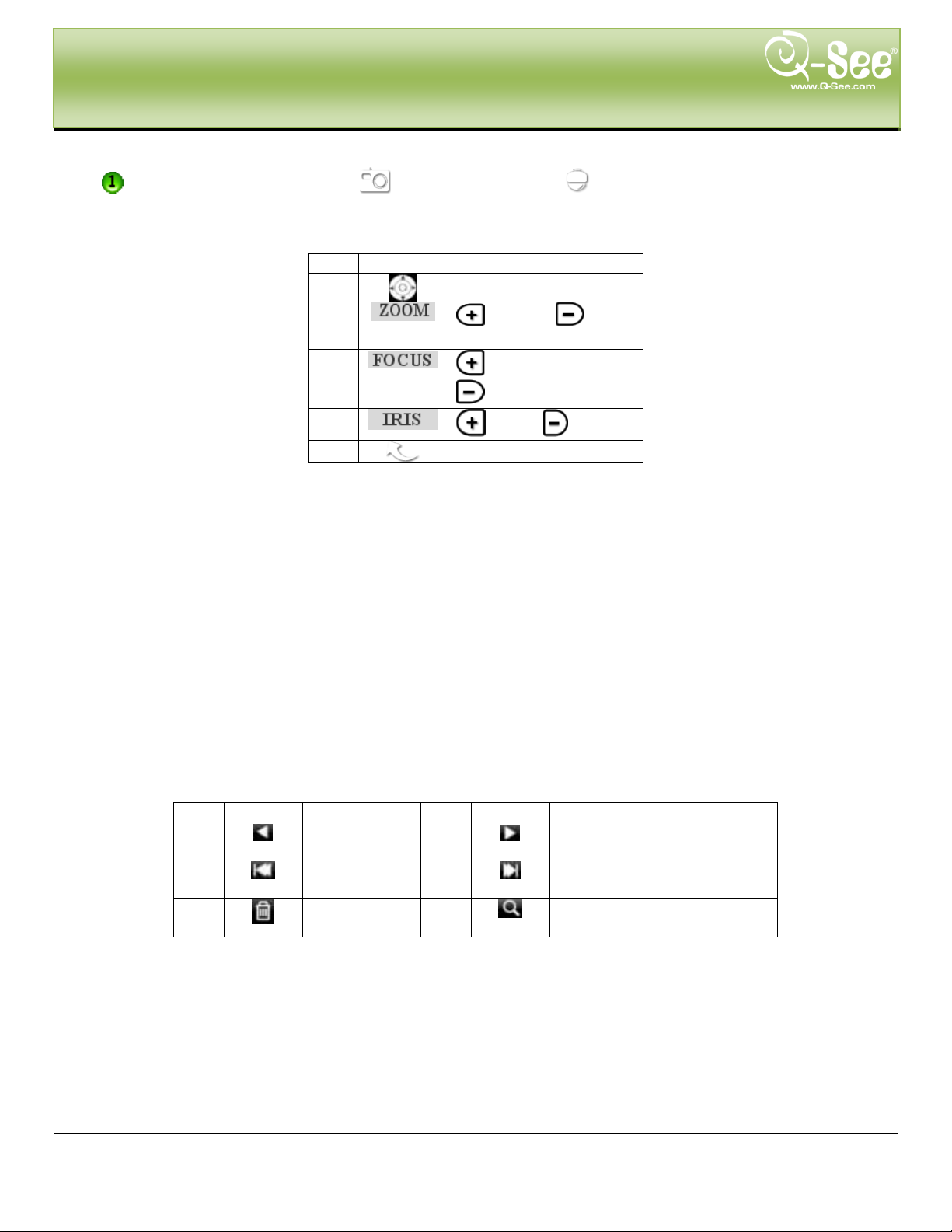
Item
Buttons
Explanations
1 pan
2
out
3
Short Focus
4
Lighter Darker
5 return to live
Item
Button
Function
Item
Button
Function
1 Previous
2 Next Picture
3 The first
Picture
4 The last picture
5 Delete
6 Search Pictures, search
page as Pic 5
MOBILE SURVEILLANCE QT428 User Manual
1. : Switch channels 2. : Picture snap. 3. : PTZ control (if server camera is PTZ
Camera only) (pic4)
PTZ Control butt ons:
Image View
Zoom in Zoom
Long Focus
Pic 4 Pic 5
picture
85 | Page

MOBILE SURVEILLANCE QT428 User Manual
8.4 For Android Mobile Clients
Software Installation
Step 1: run Google Market program Step 2: search”SuperCam”
Step 3: press “Install” button Step 4: click “OK” button
Step 5: user can view the download and install process in notifications; finished download, the software wi ll install
automatically.
86 | Page

【
【
【
【
【
【
【
【
【
MOBILE SURVEILLANCE QT428 User Manual
Login
Enter into server’s IP address (or domain name), user’s ID and password.
Click “Remember s erver” to save the settin g; click
password.
Main menu
button can quick input saved s erver address , user nam e and
Playback】
Log】
Live】
Information】
Logoff】
playback record file
log record
live view
device information view
logoff and return to l ogin interface
Image】
Server List】
Settings】
Help】
image view
device l is t
software setting
software help center
87 | Page

Mark 1
Current viewing channel
Mark 2
Channel status
Group
Set the cruise line
MOBILE SURVEILLANCE QT428 User Manual
Live view
(Fig 1) (Fig 2)
Switch channels
Snap
talk
Full screen
Upward rotates the PTZ
Leftward rot ates the PT Z
Stop rotates the PTZ
Zoom Out/Focus Out/Iris Sub Preset Select the preset p oint
PTZ, click to switch to Fig 2 interfac e
record
Live audio
Return
Downward rotates the PTZ
Rightward rotates the PTZ
Zoom In/Focus In/Iris Add
Image view
Previous
Zoom out
next
delete
Zoom in
Return to main menu
88 | Page

MOBILE SURVEILLANCE QT428 User Manual
Record playback
(Fig 3) (Fig 4)
Click the record file (Fig 3) to playback (Fig 4)
Play/pause
Full screen
Server list
stop
Return to record fil e interface (Fig 3)
Add a server list
Delete a server list
Modify a server list
Return to main menu
89 | Page

can be val id only ins ert SD card.
value, the video will be stopped
files before
MOBILE SURVEILLANCE QT428 User Manual
Config interface
Alarm setting
Storage setting
Tick off Sound Alarm,when Video Loss/Sensor/Motion happen,trigger
sound alarm; Tick off Vibrate Alarm, when Video Loss/Sensor/Motion
happen,trigger vibrate alarm
User can setup the relevant parameters of mobile video. This func tion
Path
Reserved disk space
Video clip size
Remove all recorder
Information view
Save pat h for mobile v ideo file s, the defa ult catalog is /SDCard/ . Click
but t on to chang e path.
reserved SDCard disk spac e, when the disk space is less th an setup
Single video size. When the video size is greater than setup value,
change another video files
delete all current video files
90 | Page

VIDEO
VIDEO IN
VGA RESOLUTION
352*240/704*480 (NTSC)
DISPLAY FRAME RATE
200FPS (PAL)
240FPS(NTSC)
RECORD FRAME RATE
CIF 200FPS/ D1 50FPS (PAL)
CIF 240FPS/D1 60FPS (NTSC)
AUDIO
AUDIO INPUT
ALARM OUTPUT
1CH
SIMPLEX/DUPLEX/TRIPLEX
INTERFACE
NETWORK INTERFACE
RJ45 (LAN, Internet)
COMMUNICATION INTERFACE
Mouse)
OTHER INFO
VOLTAGE
PRODUCT SPECIFICATIONS QT428 User Manual
9. PRODUCT SPECIFICATIONS
ITEM D EV ICE PARAMETER SPECIFICATION
COMPRESSION COMPRESSION FORMAT
VIDEO OUT
RECORD RESOLUTION
AUDIO OUTPUT
ALARM ALARM INPUT
STORAGE RECORD MODE
Standard H.264 Baseline
COMPOSITE 1.0V p-p/75Ω, BNC x 8
COMPOSITE 1.0V p-p/75Ω, BNC x 2, VGA x 1
1280*1024/ 1024*768/ 800*600
352*288/704*576 (PAL)
-8Db~22k, RCA x 4
-8Db~92Db, RCA x 1
NO or NC 8CH
Manual/Sensor/Timer/Motion Detection
CONTROLS PTZ CONTROL
DISK INFO DISK TYPE
Average Power Consumption
REMOTE CONTROL
WORKING TEMPERATURE
Pentaplex
RS485, USB 2.0 x 2 (One for Backup, Another for USB
Yes
Yes
SATA x 1 (up to 2TB)
12V3A
14°F to 131°F (-10°C to 55°C)/ 10% to 90%
<30W (Excluding Hard Drive)
91 | Page

APPENDIX A: F AQ’S QT426 User Manual
APPENDIX A: FAQ’s
1. The DVR does not start after connecting the power, what is wrong ?
a. The power adapter may have been damaged, or is not pr oviding enough power. Please change the adapt er.
b. The DVR may not be getting enough power from the outlet or sur ge protector it is attach ed t o.
c. There could be a problem with the system board on the DVR
2. The i ndicator lights of the DVR are on, but no output. Why?
a. The power adapter may have been damaged, or is not pr oviding enough power. Please change the adapt er
b. The video format of the DVR is different from that of the monitor.
c. Connection problem. Please check the cable and the ports of the monitor and DVR.
3. Why are no images displayed on some or al l of t he ch annels of the DVR?
a. Connection problem. Pl ease check the cables and the ports of c amera and DVR.
b. Camera problem. Plea se check the cameras by attaching them directly to TV or w or king port on DVR.
c. The video format (NTSC/PAL) of the DVR is diffe r ent from that of the cameras. Please change DVR video
format.
4. Ca nnot find HDD
a. The power adapter is not prov iding eno ugh p ower, or the adapter is not getting enough pow er fro m the out let
b. Connection problem. Pl ease check the power and data cab les on the HDD.
c. The HDD is damage d. Try a new one.
5. I c an not record, what could be the problem?
a. HDD is not formatted. Please format it manually first.
b. The record funct ion is not enabled or setup correctly. Please refer to 3.3 Recording.
c. HDD is full and recycle funct io n is not enabled. Please refer to 4.3. 4 Recycle Recording.
d. The HDD is damag ed. Try a new one.
6. I can not use the mouse, what could be the problem?
a. Wait 5 minutes after mouse connected and t hen try.
b. Mouse is not securely conne ct ed. Pl ug/unplug several times.
c. The mouse is incom patible with the system. Please try another mouse.
7 What can I do when the DVR st ar ts and displays “please wait……”all the time?
a. First possible reason: hard drive power cable and/or data cable are n ot securely connected.
Solution: Plea se check the cable connections and make sure they are secure; if sti ll not working, please
unplug them and then plug them in again.
b. Second possible reason: The system is having problems reading t he hard drive.
Solution: Try reformatting the cur r ent drive or re-placing it.
8. Why isn’t the mouse I h a ve plugged into the front USB port working?
The front USB port is only for backup to USB flash drive, and does not support a USB mouse. Please use t he
USB port on the rear panel if using a mouse.
9. How do I input password and digi tal numbers?
To input password and digital nu mb er s click the box behind password or items where you need to input
numbers, and then a small key boar d will appear. Please select number or letter to input (the default passw or d
is 123456), or you can use the digital keys on the front pan el, or t he digital keys on the remote cont r ol.
92 | Page
CPU
Intel Celeron 2.4G
MOTHERBOARD
Intel 845
HDD
80G
RAM
512M
VGA
NVIDIA GeForce MX440/FX5200
ATIRADEON 7500/X300
OS
Windows 2000(SP4 abov e) /Windows XP(SP2 above) / VI STA/Win7
DIRECTX
9.0
CPU
Intel Core(TM)2 Duo CPU E4600
MOTHERBOARD
G41/P41 chip
HDD
80G
RAM
1GB
VGA
GMA3100/NVIDIA GeForce 8400/
ATI RADEON HD3450
OS
Windows 2000(SP4 above) /Windows XP(SP2 above)/ VISTA/Win7
DIRECTX
9.0
APPENDIX A: F AQ’S QT426 User Manual
10. How do I upgrade the fir mware on the DVR?
After you downloa d the ne w firmware from the Q -Se e website at www.q-see.com, copy it onto a USB flash drive.
Then select “upgrade” in the menu.
Notice: Do not turn the system power off during the upgrade process! Doing so may damage the
chipset and prevent the DVR from starting.
11. I can get a live ima ge on the display but I ca n’ t get the menu to displa y. How can I pull up t he menu?
Hold down the ESC key to wait for login dialog box to appear.
12. I hook ed up the DVR to a TV thr ough the BNC video out port and I do not see anything on the scr een.
How do I get the video to display?
By default the DVR is setup to use a VGA monitor , if you w ant to use a TV instead then push the E SC button on
the front panel and hold it until you hear a beep, if you still do not get a display then hold the ESC button down
again until you hear a beep, t he display should come up.
13. What are the minimum conf igurations of PC for clients connecting remotely?
PC MODULE PARAMATERS
14. What are the PC configurations for 8-ch real time access with fully open mainstream channel?
PC MODULE PARAMATERS
93 | Page

FORMAT
QUALITY
(kbps)
(MB/h)
NTSC
CIF
Medium
512k
230
Higher
768k
295
Low
384k
175
APPENDIX B: RECORDING CAPACITY QT426 User Manual
APPENDIX B: CALCULATE RECORDING CAPACITY
Users can calculate the hard drive size needed according to the time saving specification an d DVR recor ding sett ings
listed below. Below is an estimated table outlining hard drive space used when the DVR is configured at various
settings.
VIDEO
RESOLUTION FRAME RATE (FPS)
30 Highest 1M 465
VIDEO
Higher 768k 297
Low 384k 173
Lower 256k 115
Lowest 128k 56
BIT RATE
SPACE USED
PAL CIF
25 Highest 1M 466
Medium 512k 235
Lower 256k 56.4
Lowest 128k 45
The calculation format is:
Total Recordin g capacity =Used space per hour (MB/h) (cover age rate of hard drive) × recording time
(hour) ×chann e l numbers
For instance, one customer uses NTSC cameras, set resolution to CIF, video quality to Lowest, frame rate to 30
fps for enabling total 8 channels. He wants the unit to record continuously for a month. Below is the calculati on:
Total Recoding capacity =56 (mb/h) X 24(hours/day) X30(days) X8(channels)
= 322560(MB)≈315(GB)
Therefore, customers who install only one S ATA H D with 320GB can expect to achieve almost one month of
recording time.
94 | Page

SSK
512MB, 1G, 2GB
NETAC
4GB
KINGSTON
2GB
AIGO
2GB
SMATTER VIDER
1GB
SANDISK
4GB
APPENDIX C: COMPATIBLE USB DRIVES QT426 User Manual
APPENDIX C: COMPATIBLE USB DRIVES
Compatible USB Drives After Testing
BRAND CAPACITY
95 | Page
 Loading...