


www.proform.com
USER8S MANUAL
ACTIVATE YOUR
WARRANTY
To register your product and activate your warranty today, go to www.proformservice.com/ registration.
CUSTOMER CARE
For service at any time, go to
www.proformservice.com.
Or call 1-888-533-1333
Mon.?Fri. 6 a.m.?6 p.m. MT
Sat. 8 a.m.?4 p.m. MT
Please do not contact the store.
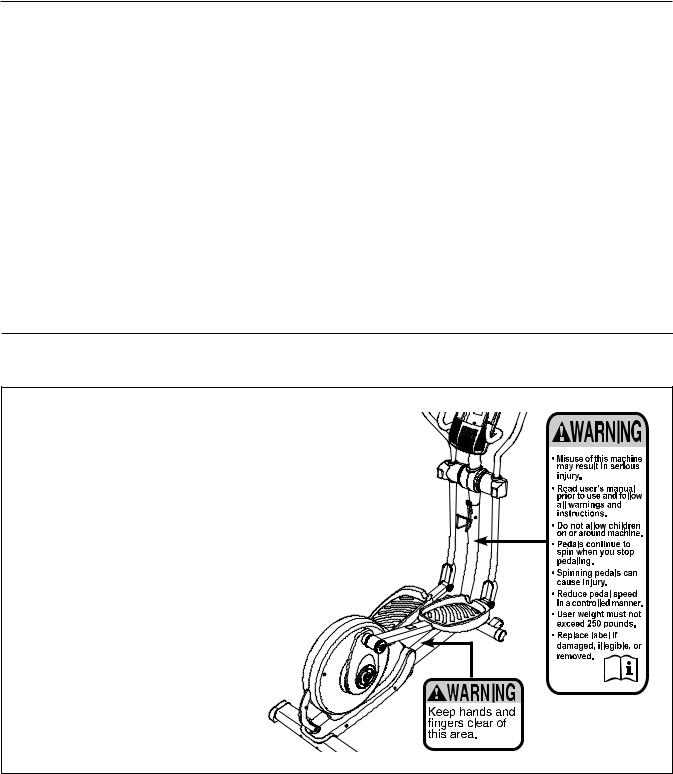
TABLE OF CONTENTS
WARNING DECAL PLACEMENT . . . . . . . . . . . . . . . . . . . . . . . . . . . . . . . . . . . . . . . . . . . . . . . . . . . . . . . . . . . . . . .2 IMPORTANT PRECAUTIONS. . . . . . . . . . . . . . . . . . . . . . . . . . . . . . . . . . . . . . . . . . . . . . . . . . . . . . . . . . . . . . . . . .3 BEFORE YOU BEGIN. . . . . . . . . . . . . . . . . . . . . . . . . . . . . . . . . . . . . . . . . . . . . . . . . . . . . . . . . . . . . . . . . . . . . . . .5 PART IDENTIFICATION CHART. . . . . . . . . . . . . . . . . . . . . . . . . . . . . . . . . . . . . . . . . . . . . . . . . . . . . . . . . . . . . . . .6 ASSEMBLY . . . . . . . . . . . . . . . . . . . . . . . . . . . . . . . . . . . . . . . . . . . . . . . . . . . . . . . . . . . . . . . . . . . . . . . . . . . . . . . .7 HOW TO USE THE ELLIPTICAL . . . . . . . . . . . . . . . . . . . . . . . . . . . . . . . . . . . . . . . . . . . . . . . . . . . . . . . . . . . . . .16 FCC INFORMATION . . . . . . . . . . . . . . . . . . . . . . . . . . . . . . . . . . . . . . . . . . . . . . . . . . . . . . . . . . . . . . . . . . . . . . . .23 MAINTENANCE AND TROUBLESHOOTING . . . . . . . . . . . . . . . . . . . . . . . . . . . . . . . . . . . . . . . . . . . . . . . . . . . .24 EXERCISE GUIDELINES . . . . . . . . . . . . . . . . . . . . . . . . . . . . . . . . . . . . . . . . . . . . . . . . . . . . . . . . . . . . . . . . . . . .25 PART LIST. . . . . . . . . . . . . . . . . . . . . . . . . . . . . . . . . . . . . . . . . . . . . . . . . . . . . . . . . . . . . . . . . . . . . . . . . . . . . . . .28 EXPLODED DRAWING. . . . . . . . . . . . . . . . . . . . . . . . . . . . . . . . . . . . . . . . . . . . . . . . . . . . . . . . . . . . . . . . . . . . . .30 ORDERING REPLACEMENT PARTS . . . . . . . . . . . . . . . . . . . . . . . . . . . . . . . . . . . . . . . . . . . . . . . . . . Back Cover LIMITED WARRANTY. . . . . . . . . . . . . . . . . . . . . . . . . . . . . . . . . . . . . . . . . . . . . . . . . . . . . . . . . . . . . . . Back Cover
WARNING DECAL PLACEMENT
This drawing shows the location(s) of the warning decal(s).
If a decal is missing or illegible, see the front cover of this manual and request a free replacement decal. Apply the decal in the location shown. Note: The decal(s) may not be shown at actual size.
PROFORM is a registered trademark of ICON IP, Inc.
2

IMPORTANT PRECAUTIONS
 WARNING: To reduce the risk of serious injury, read all important precautions and instructions in this manual and all warnings on your elliptical before using your elliptical. ICON assumes no responsibility for personal injury or property damage sustained by or through the use of this product.
1.It is the responsibility of the owner to ensure that all users of the elliptical are adequately informed of all precautions.
2.Before beginning any exercise program, consult your physician. This is especially important for persons over age 35 or persons with pre-existing health problems.
3.Use the elliptical only as described in this manual.
4.The elliptical is intended for home use only. Do not use the elliptical in a commercial, rental, or institutional setting.
5.Keep the elliptical indoors, away from moisture and dust. Do not put the elliptical in a garage or covered patio, or near water.
6.Place the elliptical on a level surface, with at least 3 ft. (0.9 m) of clearance in the front and rear of the elliptical and 2 ft. (0.6 m) on each side. To protect the floor or carpet from damage, place a mat under the elliptical.
7.Inspect and properly tighten all parts regularly. Replace any worn parts immediately.
8.Keep children under age 12 and pets away from the elliptical at all times.
9.The elliptical should not be used by persons weighing more than 250 lbs. (113 kg).
10.Wear appropriate clothes while exercising; do not wear loose clothes that could become caught on the elliptical. Always wear athletic shoes for foot protection while exercising.
11.Hold the handlebars or the upper body arms when mounting, dismounting, or using the elliptical.
12.The heart rate monitor is not a medical device. Various factors may affect the accuracy of heart rate readings. The heart rate monitor is intended only as an exercise aid in determining heart rate trends in general.
13.The elliptical does not have a freewheel; the pedals will continue to move until the flywheel stops. Reduce your pedaling speed in a controlled way.
14.Keep your back straight while using the elliptical; do not arch your back.
15.Over exercising may result in serious injury or death. If you feel faint or if you experience pain while exercising, stop immediately and cool down.
3

STANDARD SERVICE PLANS


 all
all
4

BEFORE YOU BEGIN
Thank you for purchasing the PROFORM® 600 LE elliptical. The 600 LE elliptical provides an array of features designed to make your workouts at home more effective and enjoyable.
For your benefit, read this manual carefully before you use the elliptical. If you have questions after reading this manual, please see the front cover of this
manual. To help us assist you, note the product model number and serial number before contacting us. The model number and the location of the serial number decal are shown on the front cover of this manual.
Before reading further, please familiarize yourself with the parts that are labeled in the drawing below.
Length: 5 ft. 4 in. (163 cm) |
|
Width: 2 ft. 3 in. (69 cm) |
Upper Body Arm |
|
|
Console |
Heart Rate Monitor |
Handlebar |
Fan |
|
|
|
Storage Magnet |
Water Bottle Holder* |
|
|
Wheel |
Crank Arm |
Pedal |
|
|
|
Pedal Arm Latch |
Handle |
Storage Latch |
|
|
Leveling Foot |
*Water bottle is not included |
|
|
|
5 |

PART IDENTIFICATION CHART
Use the drawings below to identify the small parts needed for assembly. The number in parentheses below each drawing is the key number of the part, from the PART LIST near the end of this manual. The number following the key number is the quantity needed for assembly. Note: If a part is not in the hardware kit, check to see if it has been preassembled. Extra parts may be included.
M4 Split |
M4 |
M8 Split |
|
|
|
|
|
Washer |
Washer |
Wave Washer |
M8 Washer |
M8 Jam Nut |
M10 Locknut |
||
Washer |
|||||||
(112)?8 |
(102)?8 |
(90)?3 |
(111)?2 |
(88)?6 |
(79)?7 |
(81)?2 |
|
M4 x 16mm |
M4 x 16mm |
M4 x 32mm |
M4 x 50mm Screw |
||||
Blunt Screw |
Round Head |
Round Head |
(108)?2 |
||||
(104)?8 |
Screw (101)?10 |
Screw (105)?6 |
|
|
|||
M8 x 23mm Shoulder |
M8 x 23mm |
Hub Screw |
M8 x 41mm |
||||
Screw (115)?4 |
Screw (84)?4 |
|
(87)?8 |
Bolt (78)?4 |
|||
|
M8 x 69mm Bolt (80)?1 |
|
M8 x 80mm Bolt (116)?2 |
|
|||
|
|
|
M10 x 80mm Carriage Bolt |
|
|
||
|
|
|
(82)?2 |
|
|
||
|
|
|
M10 x 127mm Screw (83)?2 |
|
|
||
|
|
|
6 |
|
|
|
|
ASSEMBLY
eTo hire an authorized service technician to assemble this product, call 1-800-445-2480.
eAssembly requires two persons.
ePlace all parts in a cleared area and remove the packing materials. Do not dispose of the packing materials until you nish all assembly steps.
eLeft parts are marked fLg or fLeftg and right parts are marked fRg or fRight.g
eTo identify small parts, see page 6.
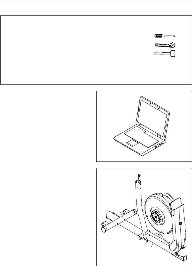
eIn addition to the included tool(s), assembly requires the following tools:
one Phillips screwdriver
one adjustable wrench
one rubber mallet
Assembly may be easier if you have a set of wrenches. To avoid damaging parts, do not use power tools.
1. Go to www.proformservice.com/registration |
|
|
|
|
1 |
|
|
on your computer and register your product. |
|
|
|
|
|
|
eactivates your warranty
esaves you time if you ever need to contact Customer Care
eallows us to notify you of upgrades and offers
Note: If you do not have Internet access, call Customer Care (see the front cover of this manual) and register your product.
2. While a second person lifts the Base (1), attach |
2 |
|
the Front Stabilizer (6) to the Base with two |
|
|
|
|
|
M10 x 80mm Carriage Bolts (82) and two M10 |
|
|
Locknuts (81). |
|
|
|
82 |
6 |
|
|
|
|
|
81 |
|
|
81 |
|
|
1 |
|
7 |
|

3.Remove the indicated screw and the shipping bracket from the Base (1). Discard the screw and the shipping bracket.
Next, tighten the Base Foot (26) into the Base (1).
4.Attach the Rear Stabilizer (7) to the Frame (2) with two M10 x 127mm Screws (83).
Next, hold the handle on the Frame (2), press the Latch (68), and lower the Frame until the Rear Stabilizer (7) rests on the floor.
3
|
1 |
|
Shipping |
|
Bracket |
|
26 |
|
Screw |
4 |
83 |
|
|
|
7 |
|
Handle |
|
2 |
|
68 |
8
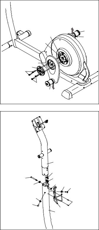
5.Hold a Hub Cover (75) and a Crank Arm (36) against the Crank (45).
Align the holes in the Hub Cover (75) and the Crank Arm (36) with the unused holes in the left side of the Crank (45).
Insert four Hub Screws (87) into the Hub Cover (75) and the Crank Arm (36), and finger tighten the Hub Screws into the Crank (45). Tighten one Hub Screw, and then tighten the Hub Screw across from the first Hub Screw. Then, tighten the remaining two Hub Screws.
Repeat this step on the right side of the elliptical.
Make sure that the Crank Arms (36) are oriented with the Crank Bushing Sleeves (43) in the positions shown. Note: There are no Pulley Screws (98) on the right side.
6.While a second person holds the Upright (3) near the Base (1), connect the Upper Wire Harness (48) to the Lower Wire Harness (49).
Tip: Avoid pinching the wires. Insert the Upright (3) into the Base (1).
Attach the Upright (3) with an M8 x 69mm Bolt (80), an M8 Split Washer (90), and an M8 Jam Nut (79). Do not tighten the Bolt yet; make sure that the Jam Nut is in the hexagonal hole in the Base.
Next, finger tighten two M8 x 23mm Screws (84) and two M8 Split Washers (90) into the Base (1).
Do not tighten the Screws yet.
Attach the Water Bottle Holder (22) to the Base
(1) with two M4 x 16mm Blunt Screws (104).
5 |
|
|
98 |
43 |
|
36 |
||
45 |
||
|
||
36 |
|
|
75 |
|
|
87 |
|
|
87 |
|
|
43 |
|
|
6 |
|
Avoid pinching the wires
|
3 |
|
|
|
48 |
|
|
80 |
49 |
|
|
90 |
79 |
90 |
84 |
|
|
|
90
104
84
22
1
9

7.Identify the Left Upright Cover (17) and hold it against the left side of the Upright (3).
Attach the Left Upright Cover (17) with two M4 x 16mm Round Head Screws (101).
Attach the Right Upright Cover (39) in the same way.
8.Identify the Left and Right Handlebars (119, 120) and orient them as shown.
Tip: Avoid pinching the Pulse Wires (118).
Attach the Left and Right Handlebars (119, 120) to the Upright (3) with two M8 x 80mm Bolts (116) and two M8 Jam Nuts (79).
7
3 39
101
17
101
8
116
3
120
119
116
118
79 
118 |
Avoid pinching the wires
10
 Loading...