


750 CardioCrossTrainer
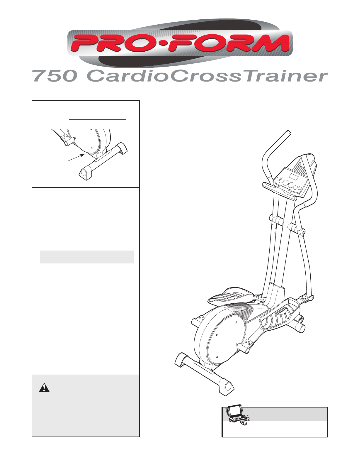
CAUTION
Read all precautions and instruc-
tions in this manual before using
this equipment. Keep this manu
-
al for future reference.
Model No. PFCCEL3805.0
Serial No.
Serial
Number
Decal
QUESTIONS?
As a manufacturer, we are com-
mitted to providing complete
customer satisfaction. If you have
questions, or if there are missing
parts, please call:
1-888-936-4266
Monday through Friday from 8:00
to 17:00 EST (excluding holidays).
www.proform.com
Visit our website at
USER’S MANUAL

TABLE OF CONTENTS
IMPORTANT PRECAUTIONS . . . . . . . . . . . . . . . . . . . . . . . . . . . . . . . . . . . . . . . . . . . . . . . . . . . . . . . . . . . . . . . .3
BEFORE YOU BEGIN . . . . . . . . . . . . . . . . . . . . . . . . . . . . . . . . . . . . . . . . . . . . . . . . . . . . . . . . . . . . . . . . . . . . . .4
ASSEMBLY . . . . . . . . . . . . . . . . . . . . . . . . . . . . . . . . . . . . . . . . . . . . . . . . . . . . . . . . . . . . . . . . . . . . . . . . . . . . . . .5
HOW TO USE THE ELLIPTICAL EXERCISER . . . . . . . . . . . . . . . . . . . . . . . . . . . . . . . . . . . . . . . . . . . . . . . . . . .9
MAINTENANCE
AND TROUBLESHOOTING . . . . . . . . . . . . . . . . . . . . . . . . . . . . . . . . . . . . . . . . . . . . . . . . . . .20
CONDITIONING GUIDELINES
. . . . . . . . . . . . . . . . . . . . . . . . . . . . . . . . . . . . . . . . . . . . . . . . . . . . . . . . . . . . . . .21
PART LIST . . . . . . . . . . . . . . . . . . . . . . . . . . . . . . . . . . . . . . . . . . . . . . . . . . . . . . . . . . . . . . . . . . . . . . . . . . . . . .22
EXPLODED DRAWING . . . . . . . . . . . . . . . . . . . . . . . . . . . . . . . . . . . . . . . . . . . . . . . . . . . . . . . . . . . . . . . . . . . .23
HOW TO ORDER REPLACEMENT PARTS . . . . . . . . . . . . . . . . . . . . . . . . . . . . . . . . . . . . . . . . . . . . .Back Cover
LIMITED WARRANTY . . . . . . . . . . . . . . . . . . . . . . . . . . . . . . . . . . . . . . . . . . . . . . . . . . . . . . . . . . . . . .Back Cover
2
PROFORM is a registered trademark of ICON IP, Inc.

3
IMPORTANT PRECAUTIONS
WARNING: To reduce the risk of serious injury, read the following important precau-
tions before using the elliptical exerciser.
1
. Read all instructions in this manual and all
warnings on the elliptical exerciser before
using the elliptical exerciser.
2. It is the responsibility of the owner to
ensure that all users of the elliptical exercis-
er are adequately informed of all precau-
tions.
3. Keep the elliptical exerciser indoors, away
from moisture and dust. Place the elliptical
exerciser on a level surface, with a mat
beneath it to protect the floor or carpet.
Make sure that there is enough clearance
around the elliptical exerciser to mount, dis-
mount, and use it.
4. Inspect and properly tighten all parts regu-
larly. Replace any worn parts immediately.
5. Keep children under 12 and pets away from
the elliptical exerciser at all times.
6. The elliptical exerciser should not be used
by persons weighing more than 115 kg (250
lbs.).
7
. Wear appropriate exercise clothes when
using the elliptical exerciser. Always wear
athletic shoes for foot protection.
8. Always hold the handgrip pulse sensor or
the handlebars when mounting, dismount-
ing, or using the elliptical exerciser.
9. The pulse sensor is not a medical device.
Various factors may affect the accuracy of
heart rate readings. The pulse sensor is
intended only as an exercise aid in deter-
mining heart rate trends in general.
10. Keep your back straight when using the
elliptical exerciser; do not arch your back.
11. If you feel pain or dizziness while exercis-
ing, stop immediately and cool down.
12. When you stop exercising, allow the pedals
to slowly come to a stop.
13. The elliptical exerciser is intended for home
use only. Do not use the elliptical exerciser
in a commercial, rental, or institutional set-
ting.
WARNING: Before beginning this or any exercise program, consult your physician.
This is especially important for persons over the age of 35 or persons with pre-existing health prob-
lems. Read all instructions before using. ICON assumes no responsibility for personal injury or
property damage sustained by or through the use of this product.
4
BEFORE YOU BEGIN
Congratulations for selecting the new PROFORM
®
7
50 CARDIO CROSSTRAINER. The PROFORM 750
is an incredibly smooth exerciser that moves your feet
in a natural elliptical path, minimizing the impact on
your knees and ankles. And the unique PROFORM
750 features adjustable resistance and a state-of-the-
art console to help you get the most from your
exercise.
For your benefit, read this manual carefully before
you use the elliptical exerciser. If you have ques-
tions after reading this manual, please call the toll-free
t
elephone number on the front cover of this manual.
To help us assist you, please note the product model
number and serial number before calling. The model
number is PFCCEL3805.0. The serial number can be
found on a decal attached to the elliptical exerciser
(see the front cover of this manual for the location of
the decal).
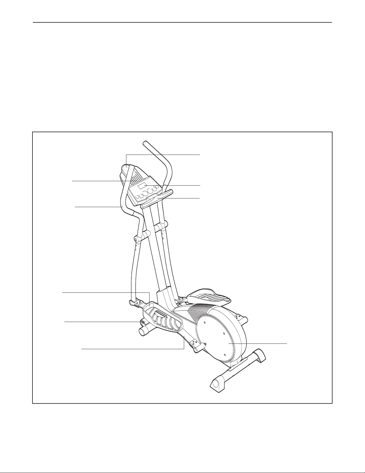
Before reading further, please familiarize yourself with
the parts that are labeled in the drawing below.
Handgrip Pulse Sensor
Handlebar
FRONT
BACK
LEFT SIDE
Pedal Spring
Pedal Disk
*No water bottle is included
Wheel
Pedal
Console
Bookrack
Water Bottle Holder*
5
ASSEMBLY
A
ssembly requires two persons.
P
lace all parts of the elliptical exerciser in a cleared area and remove the
packing materials. Do not dispose of the packing materials until assembly is completed. In addition to the
i
ncluded allen wrenches, assembly requires a phillips screwdriver , an adjustable
wrench , and a rubber mallet .
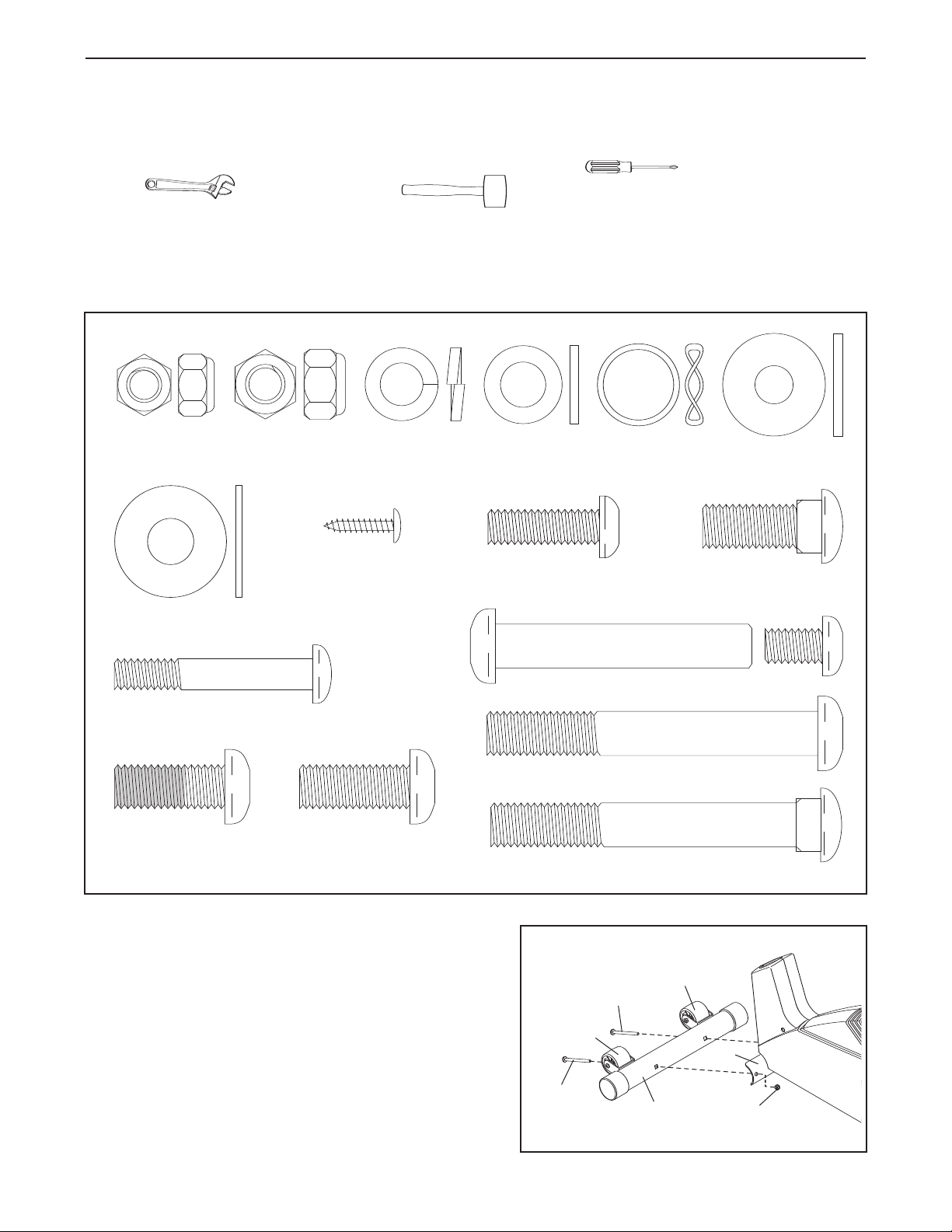
As you assemble the elliptical exerciser, use the drawings below to identify the small parts used in assembly.
The number in parenthesis below each drawing refers to the key number of the part, from the PART LIST on
page 22. The second number refers to the quantity used in assembly.
Note: Some small parts may have been
pre-assembled for shipping. If a part is not in the parts bag, check to see if it has been pre-assembled.
M4 x 16mm
Screw (52)–2
M10 x 27mm
Button Screw (67)–3
M10 Split
Washer (59)–7
M10 Nylon
Locknut (33)–6
M10 x 29mm
Carriage Bolt (28)–2
M10 Bolt Set (74)–2
Spring Bracket
Washer (35)–2
M8 Nylon
Locknut (38)–4
M8 x 45mm Button Bolt (50)–4
M10 x 27mm
Patch Screw (40)–2
M10 x 75mm Carriage
Bolt (34)–4
M10 x 76mm Button
Bolt (7)–2
M8 x 25mm Button
Screw (56)–2
Wave Washer
(79)–2
M10
Washer (65)–2
Handlebar
Washer (55)–2
1.
Identify the Front Stabilizer (10). While another person
lifts the front of the Frame (1), attach the Front
Stabilizer to the Frame with two M10 x 75mm Carriage
Bolts (34) and two M10 Nylon Locknuts (33). Make
sure that the Front Stabilizer is turned so the
Wheels (22) are not touching the floor
.
10
33
22
22
34
34
1
1
6
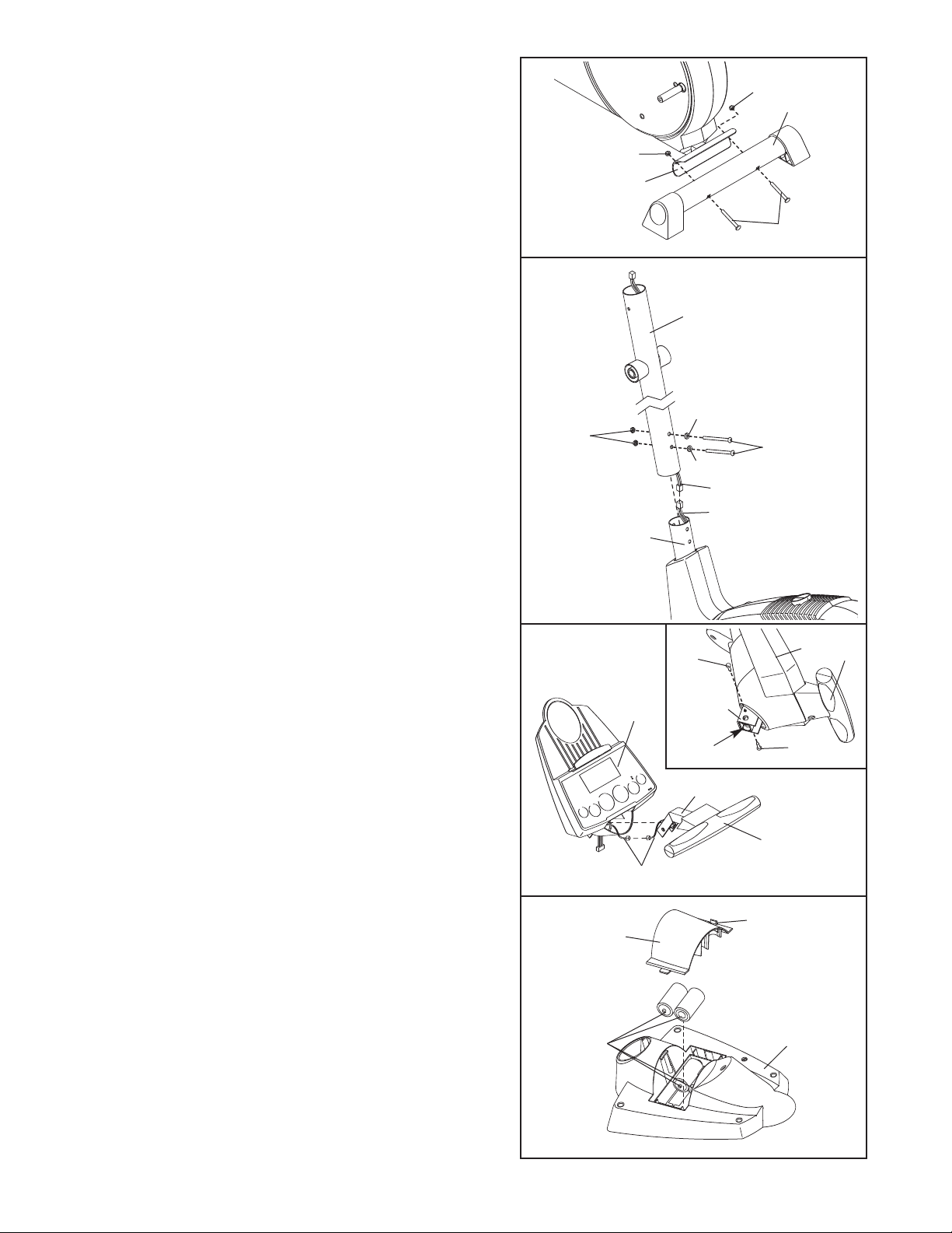
2. While another person lifts the back of the Frame (1),
attach the Rear Stabilizer (9) to the Frame with two
M
10 x 75mm Carriage Bolts (34) and two M10 Nylon
Locknuts (33).
3
4
9
1
3
2
44
1
7
43
59
59
Make sure the
Wire Harnesses
(44, 43) do not
get pinched and
damaged during
this step.
33
3. While another person holds the Upright (2) in the posi-
tion shown, connect the Extension Wire Harness (44)
to the Wire Harness (43). Carefully pull the upper
end of the Extension Wire Harness to remove any
slack. While holding the upper end of the
Extension Wire Harness,
slide the Upright onto the
Frame (1). Do not pinch the Wire Harnesses.
Attach the Upright (2) to the Frame (1) with two M10 x
76mm Button Bolts (7), two M10 Split Washers (59),
and two M10 Nylon Locknuts (33).
Do not tighten the
Nylon Locknuts yet.
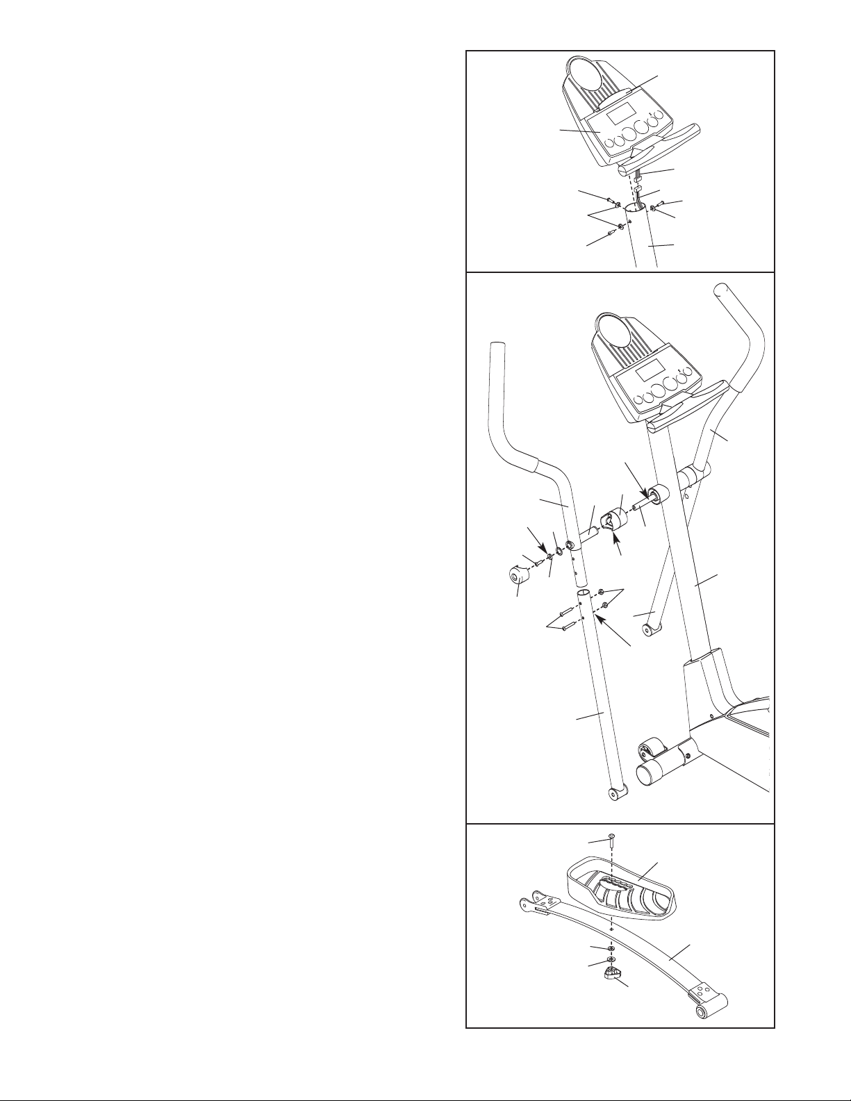
4. Connect the wire harness on the Handgrip Pulse
Sensor (29) to the indicated wire harness on the
Console (23). Insert both wire harnesses into the open-
ing in the bottom of the Console. Next, insert the metal
tube on the Handgrip Pulse Sensor into the opening in
the bottom of the Console. Be careful not to pinch
the wire harnesses.
See the inset drawing. Align the holes in the bracket on
the Console (23) with the holes in the metal tube on
the Handgrip Pulse Sensor (29). Tighten two M4 x
16mm Screws (52) through the bracket into the tube as
shown.
29
23
Wire Harnesses
4
2
33
3
3
Tube
52
23
Bracket
29
52
Tube
5.
The Console (23) requires four “D” batteries (not
included); alkaline batteries are recommended. Press
the tab on the battery cover, and lift off the battery
cover. Insert four batteries into the battery compart-
ment. Make sure that the batteries are oriented as
shown by the diagram inside the battery compart-
ment.
Reattach the battery cover.
23
Ta b
Batteries
Battery
Cover
5
50
8
38
7
6. While another person holds the Console (23) in the
position shown, connect the wire harness on the
C
onsole to the Extension Wire Harness (44). Insert the
excess wire harness into the Upright (2).
Attach the Console (23) to the Upright (2) with three
M10 x 27mm Button Screws (67) and three M10 Split
Washers (59).
Be careful to avoid pinching the wire
harnesses.
Snap the bookrack onto the Console (23) in the indicat-
ed location.
6
2
3
6
7
2
59
59
7. Identify the Left Handlebar (6), which is marked with a
sticker. Insert the Left Handlebar into one of the
Handlebar Legs (5); make sure that the Handlebar
Leg is turned so the hexagonal holes are on the
indicated side. Attach the Left Handlebar to the
Handlebar Leg with two M8 x 45mm Button Bolts (50)
and two M8 Nylon Locknuts (38).
Make sure that the
Nylon Locknuts are inside of the hexagonal holes.
Do not fully tighten the Button Bolts yet.
Attach the Right Handlebar (8) to the other Handlebar
Leg (5) in the same way.
Apply a generous amount of the included grease to the
Pivot Axle (77) and to the two Handlebar Washers (55).
Next, insert the Pivot Axle into the Upright (2) and centre
it. Reapply grease to both ends of the Pivot Axle.
Slide a Handlebar Spacer (47) onto the short tube on
each Handlebar (6, 8), and rotate the Handlebar
Spacers so the small arrows are pointing toward the
floor. Next, slide the Handlebars onto the Pivot Axle (77).
Make sure that the Handlebars are on the correct
sides.
Tighten an M8 x 25mm Button Screw (56) with a
Handlebar Washer (55) and a Wave Washer (79) into
each end of the Pivot
Axle (77). Make sure the W
ave
W
ashers are on the Pivot Axle.
Next, orient the two
Handlebar Caps (46) as shown, and press the small
tabs on the Handlebar Caps into the two Handlebar
Spacers (47).
Grease
Tube
Arrow
Grease
7
44
Wire Harness
67
Bookrack
67
47
5
2
5
56
79
55
46
6
77
8
28
27
65
1
1
13
59
8. Identify the left Pedal Spring (11), which is marked with
a sticker. Attach the Left Pedal (13) to the left Pedal
Spring with an M10 x 29mm Carriage Bolt (28), an M10
Split Washer (59), an M10 Washer (65), and a Pedal
Knob (27) as shown. Note: The Left Pedal can be
attached in any of five positions (see HOW TO
ADJUST
THE PEDALS on page 9).
Attach the Right Pedal (not shown) in the same way.
Make sure that both Pedals are in the same position.
Hexagonal
Holes
8
10. Make sure that all parts of the elliptical exerciser are properly tightened. Note: Some hardware may be
left over after assembly is completed. To protect the floor or carpet from damage, place a mat under the ellip-
tical exerciser.
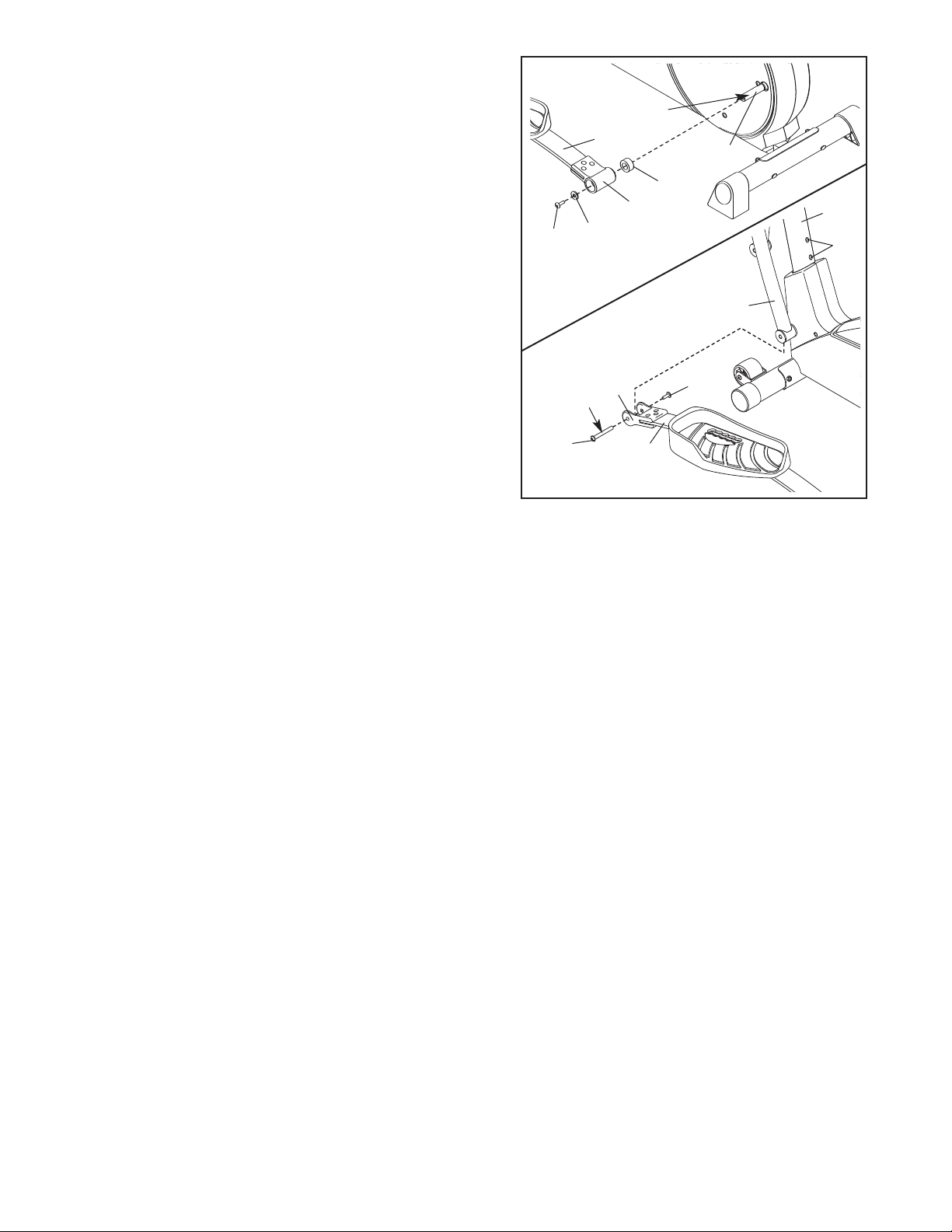
9. Apply a small amount of grease to the axle on the left
Disc Crossbar (16). Slide a Spring Spacer (63) onto the
a
xle; m
ake sure that the Spring Spacer is turned so
the flat side is facing the elliptical exerciser. Next,
s
lide the Left Rear Spring Bracket (12) on the left Pedal
Spring (11) onto the axle. Slide a Spring Bracket
Washer (35) onto an M10 x 27mm Patch Screw (40),
and tighten the Patch Screw into the axle.
Next, hold the lower end of the left Handlebar Leg (5)
inside of the Front Spring Bracket (73) on the left Pedal
Spring (11). Apply grease to an M10 Bolt Set (74).
Attach the Handlebar Leg to the Front Spring Bracket
with the Bolt Set.
Do not overtighten the Bolt Set;
the Handlebar Leg must pivot freely.
Attach the right Pedal Spring (not shown) to the right
side of the elliptical exerciser in the same way.
Tighten the two M10 x 76mm Button Bolts (7).
See step 7. Tighten the M8 x 45mm Button Bolts (50)
in the Handlebar Legs (5).
G
rease
Grease
16
74
11
11
9
40
35
63
12
74
5
2
7
73
 Loading...