


www.proform.com
Model No. PFEX64011.0
Serial No.
Write the serial number in the space above for reference.
Serial Number
Decal
QUESTIONS?
If you have questions, or if parts are damaged or missing, DO NOT
CONTACT THE STORE; please contact Customer Care.
IMPORTANT: Please register this product (see the limited warranty on the back cover of this manual) before contacting Customer Care.
CALL TOLL-FREE:
1-888-533-1333
Mon.–Fri., 6 a.m.–6 p.m. MT Sat. 8 a.m.–4 p.m. MT
ON THE WEB:
www.proformservice.com
 CAUTION
Read all precautions and instructions in this manual before using this equipment. Keep this manual for future reference.
USER’S MANUAL
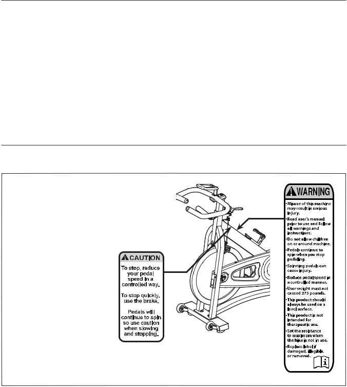
TABLE OF CONTENTS
WARNING DECAL PLACEMENT . . . . . . . . . . . . . . . . . . . . . . . . . . . . . . . . . . . . . . . . . . . . . . . . . . . . . . . . . . . . . . .2 IMPORTANT PRECAUTIONS. . . . . . . . . . . . . . . . . . . . . . . . . . . . . . . . . . . . . . . . . . . . . . . . . . . . . . . . . . . . . . . . . .3 BEFORE YOU BEGIN. . . . . . . . . . . . . . . . . . . . . . . . . . . . . . . . . . . . . . . . . . . . . . . . . . . . . . . . . . . . . . . . . . . . . . . .4 ASSEMBLY . . . . . . . . . . . . . . . . . . . . . . . . . . . . . . . . . . . . . . . . . . . . . . . . . . . . . . . . . . . . . . . . . . . . . . . . . . . . . . . .5 HOW TO USE THE EXERCISE BIKE. . . . . . . . . . . . . . . . . . . . . . . . . . . . . . . . . . . . . . . . . . . . . . . . . . . . . . . . . . .12 EXERCISE GUIDELINES . . . . . . . . . . . . . . . . . . . . . . . . . . . . . . . . . . . . . . . . . . . . . . . . . . . . . . . . . . . . . . . . . . . .19 PART LIST. . . . . . . . . . . . . . . . . . . . . . . . . . . . . . . . . . . . . . . . . . . . . . . . . . . . . . . . . . . . . . . . . . . . . . . . . . . . . . . .22 EXPLODED DRAWING. . . . . . . . . . . . . . . . . . . . . . . . . . . . . . . . . . . . . . . . . . . . . . . . . . . . . . . . . . . . . . . . . . . . . .23 ORDERING REPLACEMENT PARTS . . . . . . . . . . . . . . . . . . . . . . . . . . . . . . . . . . . . . . . . . . . . . . . . . . Back Cover LIMITED WARRANTY. . . . . . . . . . . . . . . . . . . . . . . . . . . . . . . . . . . . . . . . . . . . . . . . . . . . . . . . . . . . . . . Back Cover
WARNING DECAL PLACEMENT
This drawing shows the location(s) of the warning decal(s). If a decal is missing or illegible, see the front cover of this manual and request a free replacement decal. Apply the decal in the location shown. Note: The decal(s) may not be shown at actual size.
PROFORM is a registered trademark of ICON IP, Inc.
2

IMPORTANT PRECAUTIONS
 WARNING: To reduce the risk of serious injury, read all important precautions and instructions in this manual and all warnings on your exercise bike before using your exercise bike. ICON assumes no responsibility for personal injury or property damage sustained by or through the use of this product.
1.Before beginning any exercise program, consult your physician. This is especially important for persons over age 35 or persons with pre-existing health problems.
2.Use the exercise bike only as described in this manual.
3.It is the responsibility of the owner to ensure that all users of the exercise bike are adequately informed of all precautions.
4.The exercise bike is intended for home use only. Do not use the exercise bike in a commercial, rental, or institutional setting.
5.Keep the exercise bike indoors, away from moisture and dust. Do not put the exercise bike in a garage or covered patio, or near water.
6.Place the exercise bike on a level surface with at least 2 ft. (0.6 m) of clearance around the exercise bike. To protect the floor or carpet from damage, place a mat under the exercise bike.
7.Inspect and properly tighten all parts regularly. Replace any worn parts immediately.
8.Keep children under age 12 and pets away from the exercise bike at all times.
9.Wear appropriate clothes while exercising; do not wear loose clothes that could become caught on the exercise bike. Always wear athletic shoes for foot protection.
10.The exercise bike should not be used by persons weighing more than 275 lbs. (125 kg).
11.Always keep your back straight while using the exercise bike; do not arch your back.
12.The exercise bike does not have a freewheel; the pedals will continue to move until the flywheel stops. Reduce your pedaling speed in a controlled way.
13.To stop the flywheel quickly, press the brake lever downward.
14.When the exercise bike is not in use, tighten the resistance knob completely to prevent the flywheel from moving.
15.To avoid damaging the brake pads, do not lubricate the brake pads.
16.Over exercising may result in serious injury or death. If you feel faint or if you experience pain while exercising, stop immediately and cool down.
3
BEFORE YOU BEGIN
Thank you for selecting the new PROFORM® 315 IC exercise bike. Cycling is an effective exercise for
increasing cardiovascular fitness, building endurance, and toning the body. The 315 IC exercise bike provides a selection of features designed to make your workouts at home more effective and enjoyable.
For your benefit, read this manual carefully before you use the exercise bike. If you have questions after
reading this manual, please see the front cover of this manual. To help us assist you, note the product model number and serial number before contacting us. The model number and the location of the serial number decal are shown on the front cover of this manual.
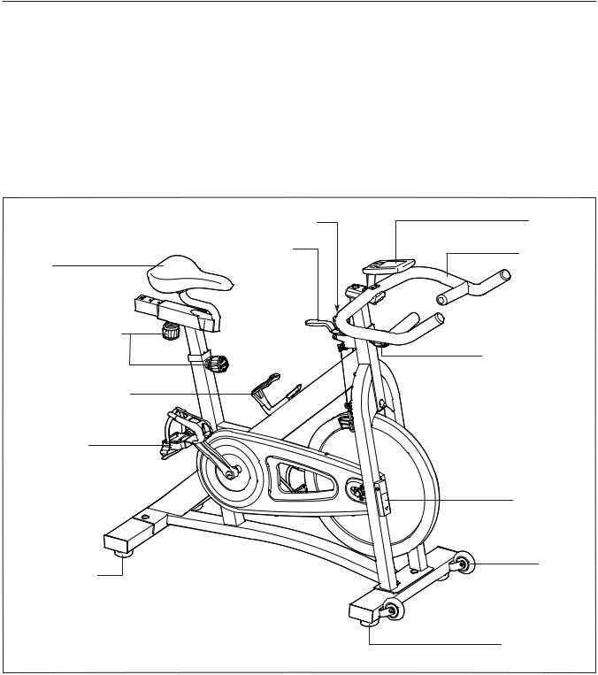
Before reading further, please familiarize yourself with the parts that are labeled in the drawing below.
Resistance Knob |
Console |
|
Brake Lever |
Handlebar |
|
Seat |
||
|
||
Adjustment Knobs |
|
|
|
Adjustment Knob |
|
Water Bottle Holder |
|
|
Pedal/Strap |
|
|
|
Transmitter |
|
Leveling Foot |
Wheel |
|
|
||
|
Leveling Foot |
4
ASSEMBLY
•Assembly requires two persons.
•Place all parts in a cleared area and remove the packing materials. Do not dispose of the packing materials until you complete all assembly steps.
•Assembly may be easier if you have your own set of wrenches. To avoid damaging parts, do not use power tools.
•In addition to the included tool(s), assembly requires the following tools:
one Phillips screwdriver
one adjustable wrench
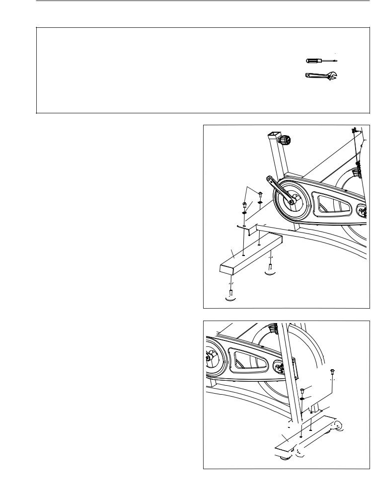
1.Remove the two screws, the two washers, and the shipping bracket (not shown) from the rear of the Frame (1) if necessary. Discard the screws, washers, and shipping bracket.
Identify the Rear Stabilizer (7), which does not have wheels.
Tighten two Leveling Feet (16) and two M10 Hex Nuts (49) into the underside of the Rear Stabilizer (7).
Attach the Rear Stabilizer (7) to the Frame (1) with two M8 x 16mm Screws (25) and two M8 Washers (24).
2.Remove the two screws, the two washers, and the shipping bracket (not shown) from the front of the Frame (1). Discard the screws, washers, and shipping bracket.
Orient the Front Stabilizer (8) so that the Wheels (21) are in the position shown.
Attach the Front Stabilizer (8) to the Frame (1) with two M8 x 16mm Screws (25) and two M8 Washers (24).
1
25
24 
1


7


 49
49


 16
16


 49
49


 16
16
2
 25
25
 24
24
25
 24
24
1


 21
21
8


 21
21
5
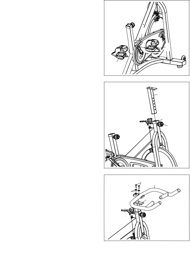
3.Identify the Right Pedal (35), which is marked with an “R.”
Using an adjustable wrench, firmly tighten the Right Pedal (35) clockwise into the Right Crank Arm (31).
Tighten the Left Pedal (38) counterclockwise into the Left Crank Arm (not shown).
4. Orient the Handlebar Post (4) as shown.
Locate the Adjustment Knob (23) on the front of the Frame (1). Loosen the Adjustment Knob and pull it outward. Then, insert the Handlebar Post
(4) into the Frame.
Move the Handlebar Post (4) upward or downward to the desired position, release the Adjustment Knob (23) into an adjustment hole in the Handlebar Post, and then tighten the Adjustment Knob. Make sure that the
Adjustment Knob is firmly engaged in an adjustment hole.
3 |
31 |
35 |
38 |
4 |
4 |
1 |
23 |
5. Attach the Handlebar (5) to the Handlebar Post |
5 |
|
|
(4) with two M10 x 25mm Screws (34) and two |
|
||
34 |
5 |
||
M10 Washers (33). |
|||
|
|||
|
33 |
|
|
|
|
4 |
6
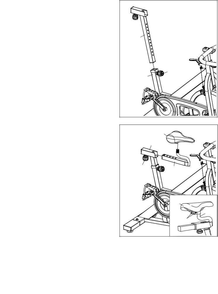
6. Orient the Seat Post (2) as shown. |
6 |
|
|
|
|
||
Locate the Adjustment Knob (23) on the rear of |
|
|
|
the Frame (1). Loosen the Adjustment Knob and |
|
|
|
pull it outward. Then, insert the Seat Post (2) into |
|
|
|
the Frame. |
|
|
|
Move the Seat Post (2) upward or downward |
2 |
|
|
to the desired position, release the Adjustment |
|
||
|
|
||
Knob (23) into an adjustment hole in the Seat |
|
|
|
Post, and then tighten the Adjustment Knob. |
|
|
|
Make sure that the Adjustment Knob is firmly |
|
|
|
engaged in an adjustment hole. |
|
|
|
|
|
23 |
|
|
|
1 |
|
7. Orient the Seat (22) and the Seat Carriage (3) as |
7 |
|
|
shown. |
22 |
||
|
|||
|
|
||
See the inset drawing. Attach the Seat (22) to |
|
2 |
|
the Seat Carriage (3) with two M8 Hex Nuts (55). |
|
||
|
|
||
Make sure that the nose of the Seat is point- |
|
|
|
ing straight ahead before you tighten the Hex |
|
|
|
Nuts. |
|
|
|
Locate the Adjustment Knob (23) on the Seat |
23 |
3 |
|
|
|||
Post (2). Loosen the Adjustment Knob and pull it |
|
|
|
outward. Then, insert the Seat Carriage (3) into |
|
|
|
the Seat Post. |
|
|
|
Slide the Seat Carriage (3) to the desired posi- |
|
|
|
tion and then release the Adjustment Knob (23) |
|
|
|
into one of the adjustment holes in the Seat |
|
22 |
|
Carriage. Make sure that the Adjustment Knob |
|
||
|
|
||
is firmly engaged in an adjustment hole. |
|
3 |
|
|
|
||
|
|
55 |
|
|
7 |
|
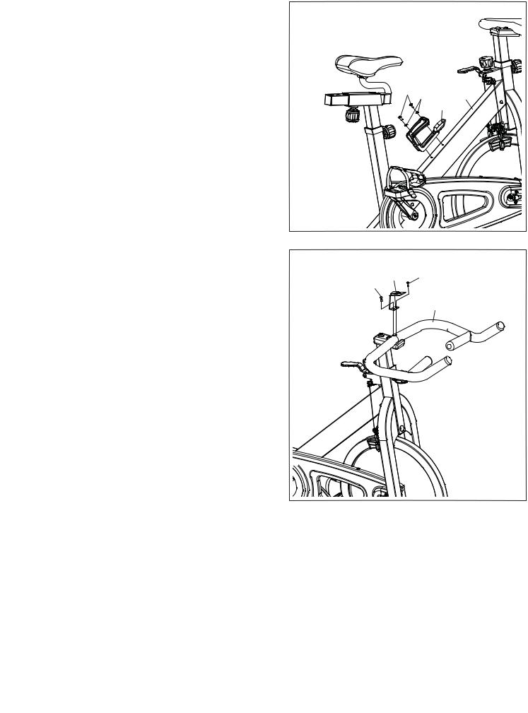
8.Attach the Water Bottle Holder (60) to the Frame
(1) with two M5 x 12mm Screws (39) and two M5 Washers (52).
9.Attach the Console Bracket (64) to the Handlebar (5) with two M5 x 12mm Screws (39).
8
39 52 |
1 |
|
60 |
9
64 39
39
5
8
 Loading...