


700
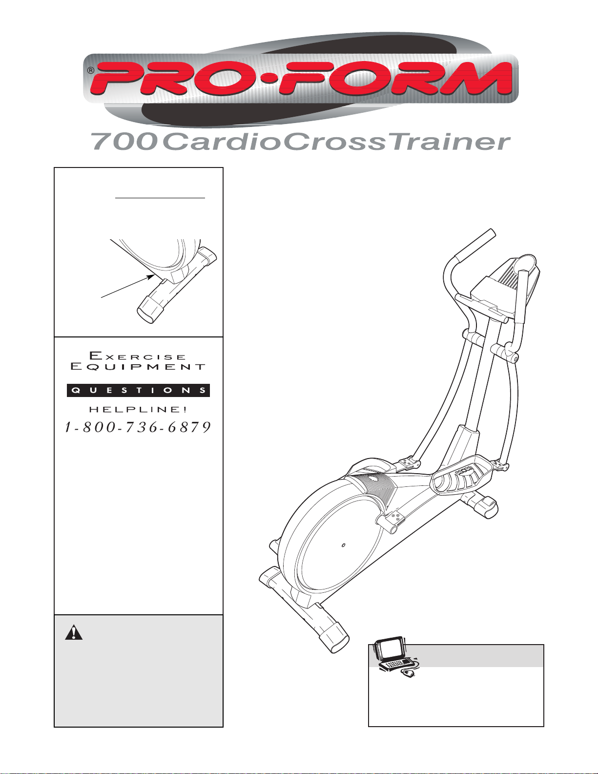
Serial
Number
Decal
USER’S MANUAL
CAUTION
Read all precautions and
instructions in this manual
before using this equipment.
Keep this manual for future
reference.
Model No. 831.285281
Serial No.
Patent Pending
SEARS, ROEBUCK AND CO.,
HOFFMAN ESTATES, IL 60179
Write the serial number in the
space above for future reference.
Visit our website at
www.proform.com
new products, prizes,
fitness tips, and much more!

TABLE OF CONTENTS
IMPORTANT PRECAUTIONS . . . . . . . . . . . . . . . . . . . . . . . . . . . . . . . . . . . . . . . . . . . . . . . . . . . . . . . . . . . . .3
BEFORE YOU BEGIN . . . . . . . . . . . . . . . . . . . . . . . . . . . . . . . . . . . . . . . . . . . . . . . . . . . . . . . . . . . . . . . . . . .4
ASSEMBLY . . . . . . . . . . . . . . . . . . . . . . . . . . . . . . . . . . . . . . . . . . . . . . . . . . . . . . . . . . . . . . . . . . . . . . . . . . .5
HOW TO USE THE ELLIPTICAL CROSSTRAINER . . . . . . . . . . . . . . . . . . . . . . . . . . . . . . . . . . . . . . . . . . . . .9
MAINTENANCE AND TROUBLESHOOTING . . . . . . . . . . . . . . . . . . . . . . . . . . . . . . . . . . . . . . . . . . . . . . . . .20
CONDITIONING GUIDELINES . . . . . . . . . . . . . . . . . . . . . . . . . . . . . . . . . . . . . . . . . . . . . . . . . . . . . . . . . . . .21
PART LIST . . . . . . . . . . . . . . . . . . . . . . . . . . . . . . . . . . . . . . . . . . . . . . . . . . . . . . . . . . . . . . . . . . . . . . . . . . .22
EXPLODED DRAWING . . . . . . . . . . . . . . . . . . . . . . . . . . . . . . . . . . . . . . . . . . . . . . . . . . . . . . . . . . . . . . . . .23
HOW TO ORDER REPLACEMENT PARTS . . . . . . . . . . . . . . . . . . . . . . . . . . . . . . . . . . . . . . . . . . .Back Cover
FULL 90 DAY WARRANTY . . . . . . . . . . . . . . . . . . . . . . . . . . . . . . . . . . . . . . . . . . . . . . . . . . . . . . .Back Cover
2
PROFORM is a registered trademark of ICON Health & Fitness, Inc.

3
IMPORTANT PRECAUTIONS
WARNING:To reduce the risk of serious injury, read the following important precau-
tions before using the elliptical crosstrainer.
1. Read all instructions in this manual before
using the elliptical crosstrainer.
2. It is the responsibility of the owner to ensure
that all users of the elliptical crosstrainer
are adequately informed of all precautions.
3. Place the elliptical crosstrainer on a level
surface, with a mat beneath it to protect the
floor or carpet. Keep the elliptical crosstrainer indoors, away from moisture and dust.
4. Inspect and properly tighten all parts regularly. Replace any worn parts immediately.
5. Keep children under 12 and pets away from
the elliptical crosstrainer at all times.
6. The elliptical crosstrainer should not be used
by persons weighing more than 250 pounds.
7. Wear appropriate exercise clothing when
using the elliptical crosstrainer. Always wear
athletic shoes for foot protection.
8. Always hold the handgrip pulse sensor or the
handlebars when mounting, dismounting, or
using the elliptical crosstrainer.
9. The pulse sensor is not a medical device.
Various factors may affect the accuracy of
heart rate readings. The pulse sensor is
intended only as an exercise aid in determining heart rate trends in general.
10. Keep your back straight when using the elliptical crosstrainer; do not arch your back.
11. If you feel pain or dizziness at any time
while exercising, stop immediately and
begin cooling down.
12. When you stop exercising, allow the pedals
to slowly come to a stop.
13. The elliptical crosstrainer is intended for
home use only. Do not use the elliptical
crosstrainer in a commercial, rental, or institutional setting.
WARNING:Before beginning this or any exercise program, consult your physician.
This is especially important for persons over the age of 35 or persons with pre-existing health problems. Read all instructions before using. SEARS assumes no responsibility for personal injury or
property damage sustained by or through the use of this product.
4
BEFORE YOU BEGIN
Congratulations for selecting the new PROFORM
®
700 CARDIO CROSSTRAINER. The PROFORM®700
is an incredibly smooth exerciser that moves your feet
in a natural elliptical path, minimizing the impact on
your knees and ankles. And the unique PROFORM
®
700 features adjustable resistance and a state-of-theart console to help you get the most from your exercise. Welcome to a whole new world of natural, elliptical-motion exercise from PROFORM.
For your benefit, read this manual carefully before
you use the elliptical crosstrainer. If you have addi-
tional questions, please call our toll-free HELPLINE at
1-800-736-6879, Monday through Saturday, 7 a.m.
until 7 p.m. Central Time (excluding holidays). To help
us assist you, please note the product model number
and serial number before calling. The model number
is 831.285281. The serial number can be found on a
decal attached to the elliptical crosstrainer (see the
front cover of this manual for the location of the decal).
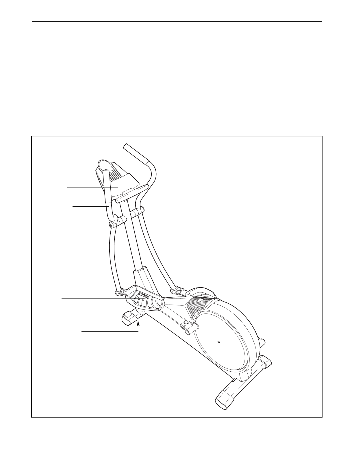
Before reading further, please look at the drawing
below and familiarize yourself with the parts that are
labeled.
Handgrip Pulse Sensor
Handlebar
FRONT
BACK
LEFT SIDE
Flex Bar
Pedal Disk
*No water bottle
is included
Wheel
Pedal
Console
Book Rack
Water Bottle Holder*
Leveling Foot
5
ASSEMBLY
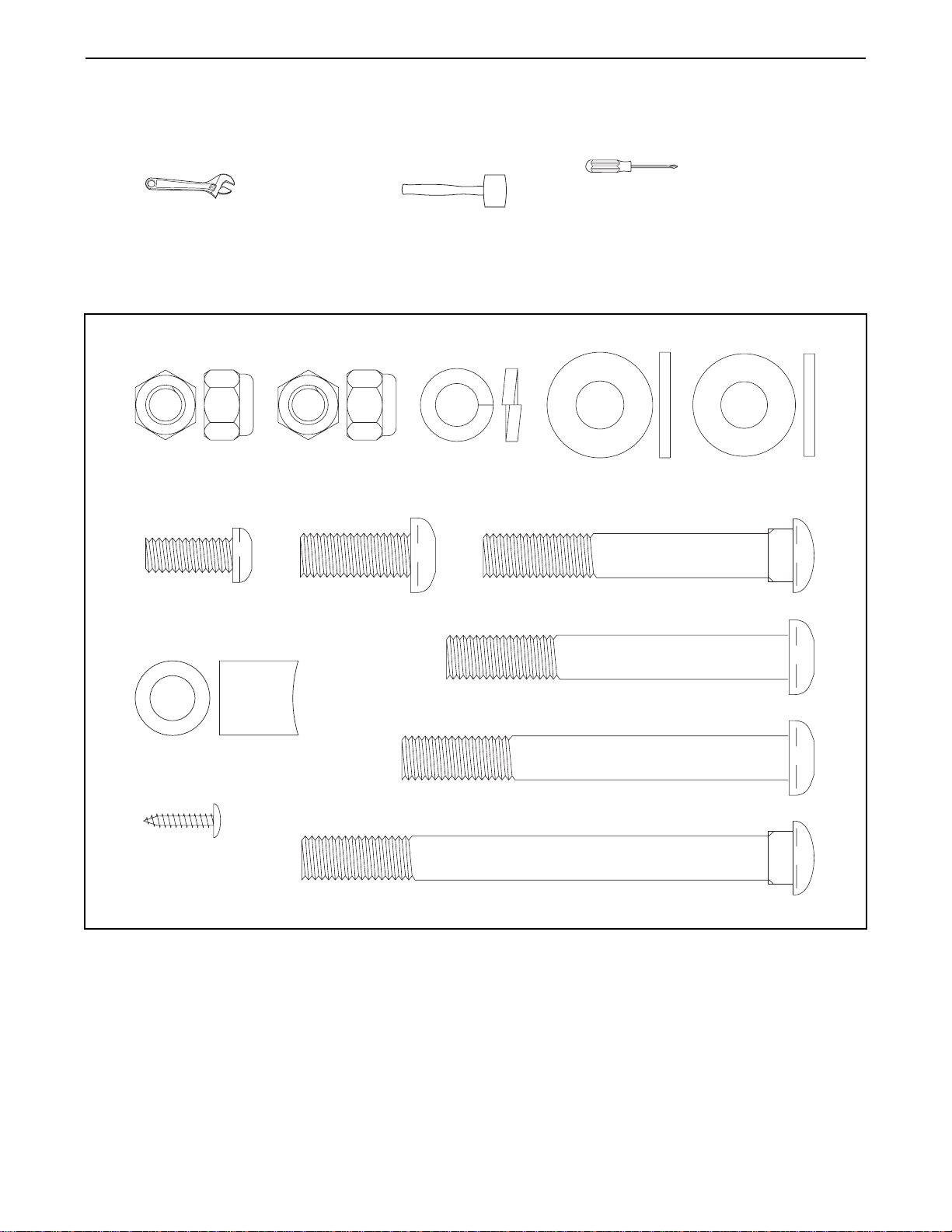
Assembly requires two persons. Place all parts of the elliptical crosstrainer in a cleared area and remove the
packing materials. Do not dispose of the packing materials until assembly is completed. In addition to the
included allen wrenches, assembly requires a phillips screwdriver , an adjustable
wrench , and a rubber mallet .
As you assemble the elliptical crosstrainer, use the drawings below to identify the small parts used in assembly.
The number in parenthesis below each drawing refers to the key number of the part, from the PART LIST on
page 22. The second number refers to the quantity used in assembly. Note: Some small parts may have been
pre-assembled for shipping. If a part is not in the parts bag, check to see if it has been pre-assembled.
M10 Nylon
Locknut (29)–4
M8 x 19mm Button
Screw (22)–2
Frame Spacer (83)–1
M4 x 16mm
Screw (66)–2
M10 Zinc Nylon
Locknut (88)–2
M10 x 27mm
Screw (71)–3
M10 Split
Washer (70)–4
M10 x 112mm Carriage Bolt (34)–4
M10.3 Black
Washer (53)–2
Adjustment Bolt (20)–2
M10 x 78mm Button Bolt (27)–2
M10 x 88mm Button Bolt (63)–1
M10 Zinc
Washer (38)–6
6
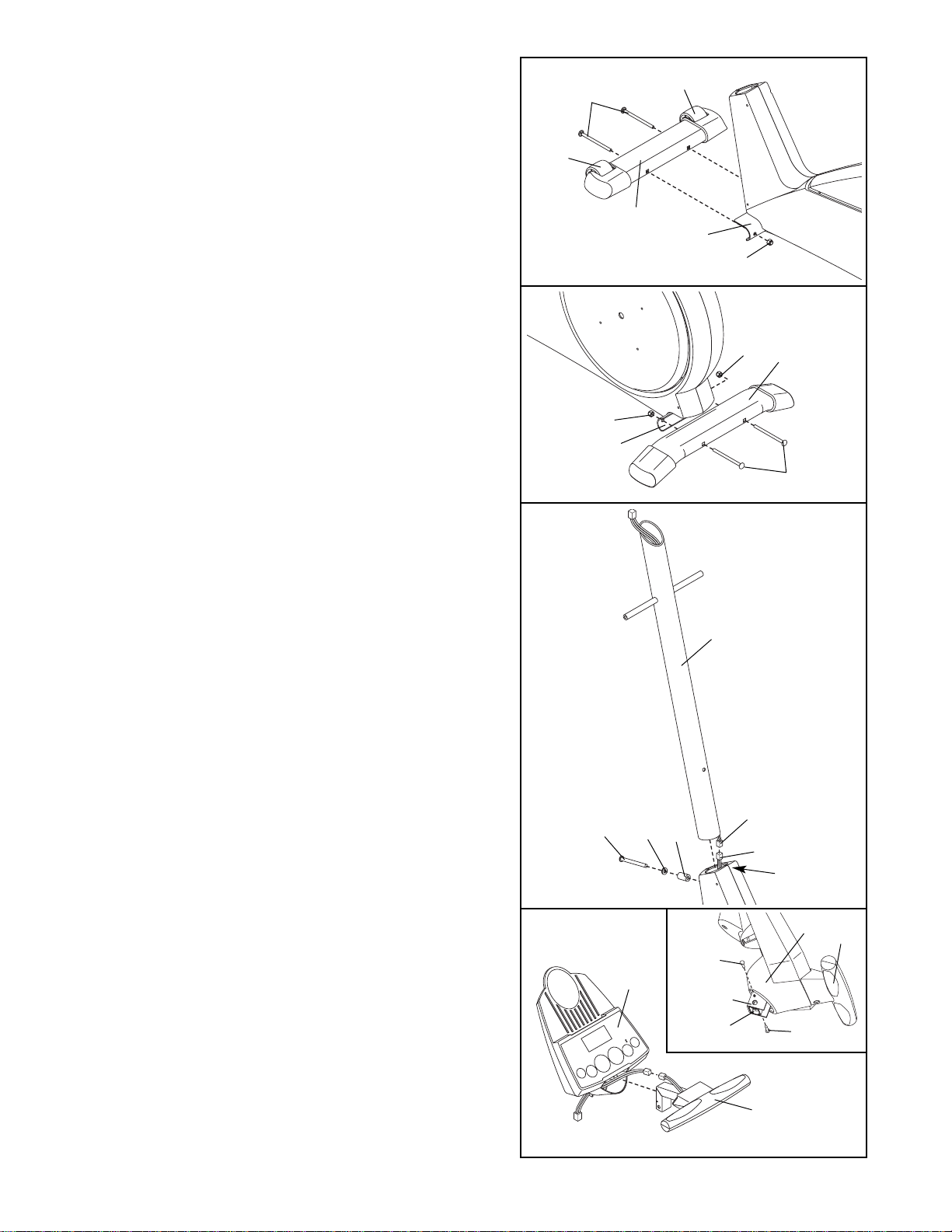
1. Identify the Front Stabilizer (3), which has Wheels (32)
attached to it. While another person lifts the front of the
Frame (1), attach the Front Stabilizer to the Frame
with two M10 x 112mm Carriage Bolts (34) and two
M10 Nylon Locknuts (29). Make sure that the Front
Stabilizer is turned so the Wheels are not touching
the floor.
3
29
32
32
34
1
1
2. While another person lifts the back of the Frame (1),
attach the Rear Stabilizer (4) to the Frame with two
M10 x 112mm Carriage Bolts (34) and two M10 Nylon
Locknuts (29).
34
4
1
3
2
86
87
1
63
83
70
3. While another person holds the Upright (2) in the posi-
tion shown, connect the Upper Wire Harness (86) to
the Lower Wire Harness (87). Carefully pull the
upper end of the Upper Wire Harness to remove
any slack from the Wire Harnesses.
Insert the Upright (2) into the front of the Frame (1) as
shown. Be careful to avoid pinching the Wire
Harnesses (86, 87). Slide an M10 Split Washer (70)
and a Frame Spacer (83) onto the M10 x 88mm Button
Bolt (63), and insert the Button Bolt into the Frame and
the Upright. Make sure that the concave end of the
Frame Spacer is turned toward the Frame. Tighten
the Button Bolt into the welded nut on the Frame.
4. Connect the wire harness on the Handgrip Pulse
Sensor (81) to the indicated wire harness on the
Console (5). Insert both wire harnesses into the opening in the bottom of the Console.
Refer to the inset drawing. Insert the metal tube on the
Handgrip Pulse Sensor (81) into the metal bracket
inside the Console (5) as shown. Be careful to avoid
pinching the wire harnesses. Align the holes in the
metal tube with the holes in the metal bracket, and
tighten two M4 x 16mm Screws (66) into the indicated
holes.
81
5
66
5
Bracket
66
81
4
2
29
29
Tube
8. Hold the lower end of the Left Handlebar (9) inside of
the Front Flex Bracket (17) on the left Flex Bar (14).
Apply grease to an M10 x 78mm Button Bolt (27).
Attach the Left Handlebar (9) to the Front Flex Bracket
(17) with the Button Bolt, two M10 Zinc Washers (38),
and an M10 Zinc Nylon Locknut (88). Do not over-
tighten the Nylon Locknut; the Left Handlebar must
be able to pivot freely.
Attach the Right Handlebar (10) to the right Front Flex
Bracket (17) in the same way.
17
17
14
27
38
38
88
Grease
7
6. While another person holds the Console (5) in the
position shown, connect the wire harness on the
Console to the Upper Wire Harness (86). Insert the
excess wire harness into the Upright (2).
Attach the Console (5) to the Upright (2) with three
M10 x 27mm Screws (71) and three M10 Split
Washers (70). Be careful to avoid pinching the wire
harnesses.
6
5
86
71
71
7. Apply a small amount of the included grease to the left
and right axles on the Upright (2).
Identify the Left Handlebar (9) (refer to the drawing on
page 4, if necessary). Carefully slide an Upright Spacer
(26), a Handlebar Spacer (25), the Left Handlebar, and a
Handlebar Cap (23) onto the left axle on the Upright (2)
as shown. Slide an M10.3 Black Washer (53) onto an M8
x 19mm Button Screw (22), and tighten the Button Screw
into the axle.
Attach the Right Handlebar (10) in the same way.
Grease
7
8
2
Wire Harness
70
70
71
26
25
9
2
10
23
53
22
9
10
5. The Console (5) requires four “D” batteries (not includ-
ed); alkaline batteries are recommended. Press the tab
on the battery cover, and lift off the battery cover.
Insert four batteries into the battery compartment.
Make sure that the batteries are oriented as shown
by the diagram inside the battery compartment.
Reattach the battery cover.
5
5
Tab
Batteries
Battery
Cover
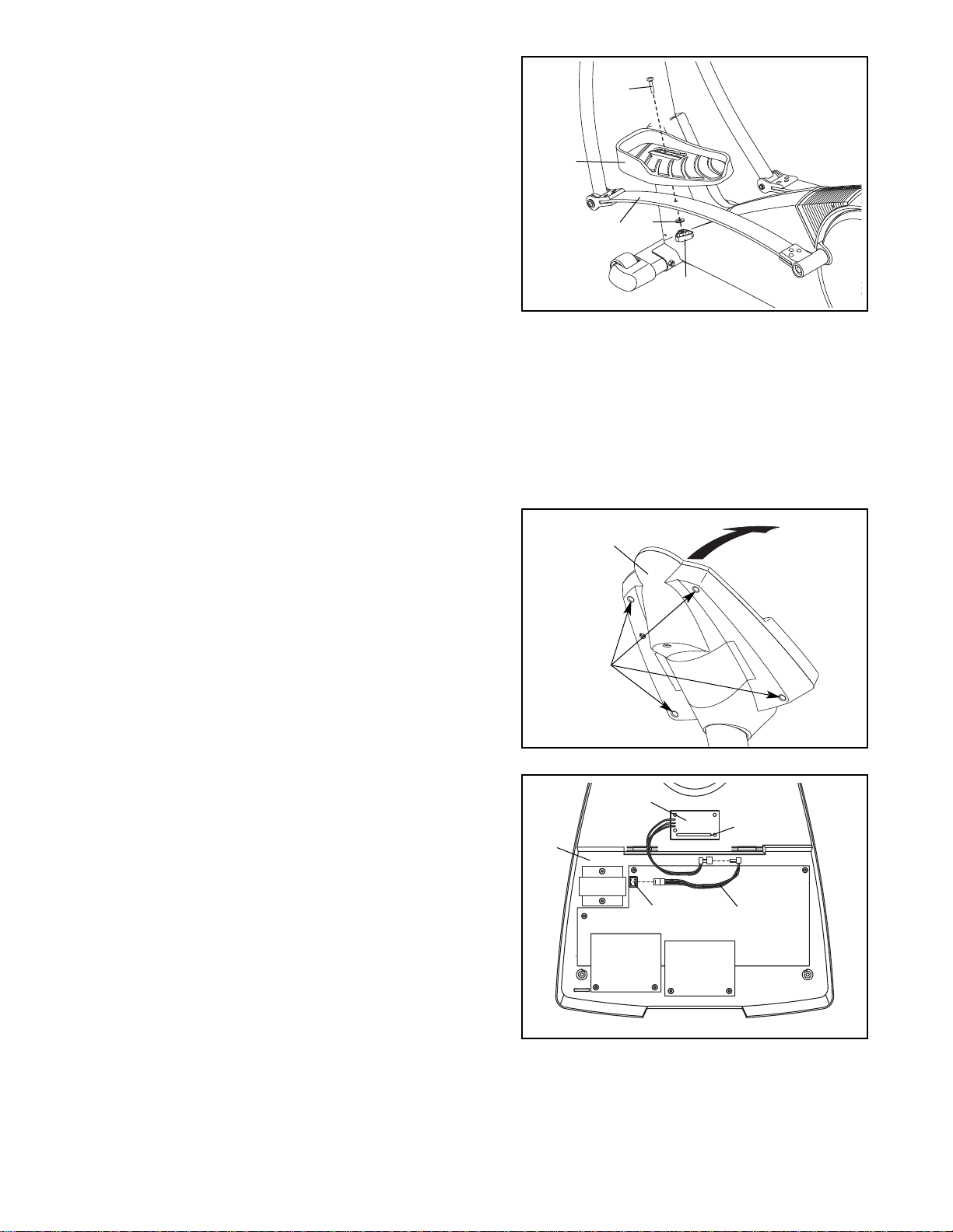
INSTALLING THE RECEIVER FOR THE OPTIONAL CHEST PULSE SENSOR
If you purchase the optional chest pulse sensor (refer to page 20), follow the steps below to install the receiver
and the jumper wire included with the chest pulse sensor.
1. Remove the four indicated screws from the back of the
Console (5). Lift off the front of the Console.
2. Plug the jumper wire (A) into the indicated jack on the
Console (5). Connect the other end of the jumper wire
to the wire on the receiver (B).
Next, peel the paper off the adhesive pad on the back
of the receiver (B). Orient the receiver as shown, and
press it onto the Console (5) in the indicated location.
Refer to step 1 above. Reattach the front of the
Console (5) with the four screws. Make sure that no
wires are pinched.
8
10.Make sure that all parts of the elliptical crosstrainer are properly tightened. Note: Some hardware may
be left over after assembly is completed. To protect the floor or carpet from damage, place a mat under the
elliptical crosstrainer.
9
20
15
14
38
13
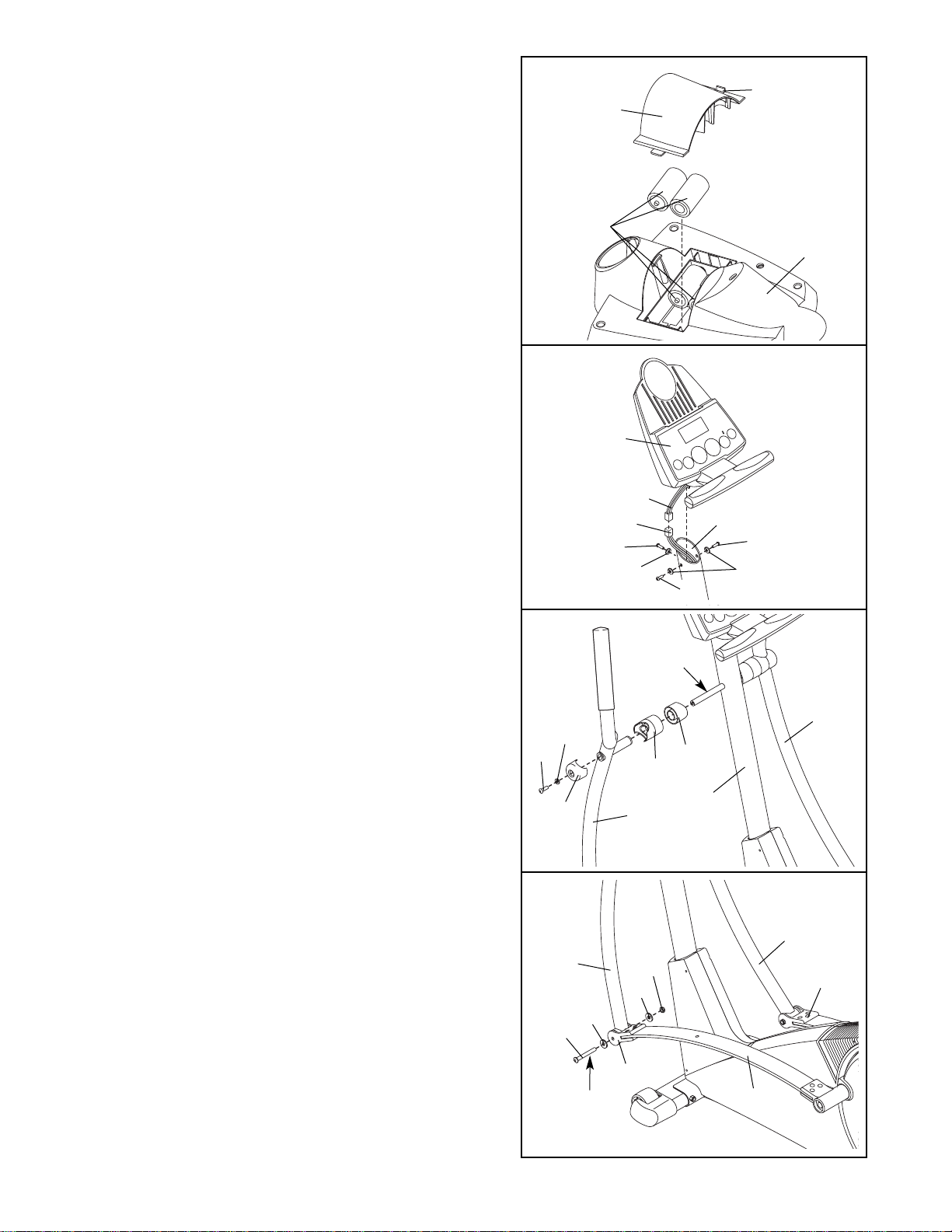
9. Identify the Left Pedal (13). Attach the Left Pedal to the
left Flex Bar (14) with an Adjustment Bolt (20), an M10
Zinc Washer (38), and an Adjustment Knob (15) as
shown. Note: The Left Pedal can be attached in any of
five positions (see HOW TO ADJUST THE PEDALS on
page 9).
Attach the Right Pedal (not shown) in the same way.
Make sure that both Pedals are in the same position.
B
5
Jack
5
Screws
Lift
Here
1
A
Cylinder
2
 Loading...