


Model No. PETL79810.0 Serial No.
Write the serial number in the space above for reference.
Serial Number
Decal
QUESTIONS?
If you have questions, or if there are missing parts, please contact us:
UK
Call: 08457 089 009
From Ireland: 053 92 36102
Website: www.iconsupport.eu
E-mail: csuk@iconeurope.com
Write:
ICON Health & Fitness, Ltd. c/o HI Group PLC
Express Way
Whitwood, West Yorkshire
WF10 5QJ
UK
AUSTRALIA
Call: 1-800-237-173
E-mail:
australiacc@iconfitness.com
CAUTION
Read all precautions and instructions in this manual before using this equipment. Save this manual for future reference.
USERʼS MANUAL
www.iconeurope.com

TABLE OF CONTENTS
WARNING DECAL PLACEMENT . . . . . . . . . . . . . . . . . . . . . . . . . . . . . . . . . . . . . . . . . . . . . . . . . . . . . . . . . . . . . .2 IMPORTANT PRECAUTIONS . . . . . . . . . . . . . . . . . . . . . . . . . . . . . . . . . . . . . . . . . . . . . . . . . . . . . . . . . . . . . . . .3 BEFORE YOU BEGIN . . . . . . . . . . . . . . . . . . . . . . . . . . . . . . . . . . . . . . . . . . . . . . . . . . . . . . . . . . . . . . . . . . . . . .5 ASSEMBLY . . . . . . . . . . . . . . . . . . . . . . . . . . . . . . . . . . . . . . . . . . . . . . . . . . . . . . . . . . . . . . . . . . . . . . . . . . . . . . .6 HOW TO USE THE CHEST PULSE SENSOR . . . . . . . . . . . . . . . . . . . . . . . . . . . . . . . . . . . . . . . . . . . . . . . . . . .15 OPERATION AND ADJUSTMENT . . . . . . . . . . . . . . . . . . . . . . . . . . . . . . . . . . . . . . . . . . . . . . . . . . . . . . . . . . . .16 HOW TO FOLD AND MOVE THE TREADMILL . . . . . . . . . . . . . . . . . . . . . . . . . . . . . . . . . . . . . . . . . . . . . . . . . .24 TROUBLESHOOTING . . . . . . . . . . . . . . . . . . . . . . . . . . . . . . . . . . . . . . . . . . . . . . . . . . . . . . . . . . . . . . . . . . . . .25 EXERCISE GUIDELINES . . . . . . . . . . . . . . . . . . . . . . . . . . . . . . . . . . . . . . . . . . . . . . . . . . . . . . . . . . . . . . . . . . .28 PART LIST . . . . . . . . . . . . . . . . . . . . . . . . . . . . . . . . . . . . . . . . . . . . . . . . . . . . . . . . . . . . . . . . . . . . . . . . . . . . . .30 EXPLODED DRAWING . . . . . . . . . . . . . . . . . . . . . . . . . . . . . . . . . . . . . . . . . . . . . . . . . . . . . . . . . . . . . . . . . . . .32 ORDERING REPLACEMENT PARTS . . . . . . . . . . . . . . . . . . . . . . . . . . . . . . . . . . . . . . . . . . . . . . . . . .Back Cover RECYCLING INFORMATION . . . . . . . . . . . . . . . . . . . . . . . . . . . . . . . . . . . . . . . . . . . . . . . . . . . . . . . . .Back Cover
WARNING DECAL PLACEMENT
This drawing shows the locations of the warning decals. If a decal is missing or illegible, call the telephone number on the front cover of this manual and request a free replacement decal. Apply the decal in the location shown. Note: The decals may not be shown at actual size.
PROFORM is a registered2trademark of ICON IP, Inc.

IMPORTANT PRECAUTIONS
WARNING: To reduce the risk of serious injury, read all important precautions and inctions in this manual and all warnings on your treadmill before using your treadmill. ICON assumes no responsibility for personal injury or property damage sustained by or through the use of
this product.
1. Before beginning any exercise program, consult your physician. This is especially important for persons over age 35 or persons with pre-existing health problems.
2. It is the responsibility of the owner to ensure that all users of this treadmill are adequately informed of all warnings and precautions.
3. Use the treadmill only as described.
4. Keep the treadmill indoors, away from moisture and dust. Do not put the treadmill in a garage or covered patio, or near water.
5. Place the treadmill on a level surface, with at least 8 ft. (2.4 m) of clearance behind it and 2 ft. (0.6 m) on each side. Do not place the treadmill on any surface that blocks air openings. To protect the floor or carpet from damage, place a mat under the treadmill.
6. Do not operate the treadmill where aerosol products are used or where oxygen is being administered.
7. Keep children under age 12 and pets away from the treadmill at all times.
8. The treadmill should be used only by persons weighing 300 lbs. (135 kg) or less.
9. Never allow more than one person on the treadmill at a time.
10. Wear appropriate exercise clothes when using the treadmill. Do not wear loose clothes that could become caught in the treadmill. Athletic support clothes are recommended for both men and women. Always wear athletic shoes. Never use the treadmill with bare feet, wearing only stockings, or in sandals.
3

19.Never leave the treadmill unattended while it is running. Always remove the key, unplug the power cord, and press the power switch into the off position when the treadmill is not in use. (See the drawing on page 5 for the location of the power switch.)
20.Do not attempt to raise, lower, or move the treadmill until it is properly assembled. (See ASSEMBLY on page 6, and HOW TO FOLD AND MOVE THE TREADMILL on page 24.) You must be able to safely lift 45 lbs. (20 kg) to raise, lower, or move the treadmill.
21.When folding or moving the treadmill, make sure that the storage latch is holding the frame securely in the storage position.
22.Never insert any object into any opening on the treadmill.
SAVE THESE
23. Inspect and properly tighten all parts of the treadmillDANGER:regularly.
24. Always unplug the power cord immediately after use, before cleaning the treadmill, and before performing the mainte- nance and adjustment procedures described in this manual. Never remove the motor hood unless instructed to do so by an authorized service representative. Servicing other than the procedures in this manual should be performed by an authorized service representative only.
25. This treadmill is intended for in-home use only. Do not use this treadmill in a commercial, rental, or institutional setting.
26. Over exercising may result in serious injury or death. If you feel faint or if you experience pain while exercising, stop immediately and cool down.
INSTRUCTIONS
4
BEFORE YOU BEGIN
Thank you for selecting the revolutionary PROFORM® 705 ZLT treadmill. The 705 ZLT treadmill offers an impressive selection of features designed to make your workouts at home more enjoyable and effective. And when youʼre not exercising, the unique treadmill can be folded up, requiring less than half the floor space of other treadmills.
For your benefit, read this manual carefully before using the treadmill. If you have questions after read-
ing this manual, please see the front cover of this man- ual. To help us assist you, please note the product model number and serial number before contacting us. The model number and the location of the serial number decal are shown on the front cover of this manual.
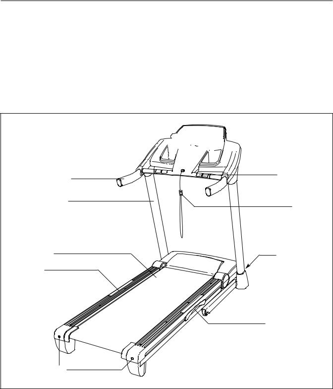
Before reading further, please review the drawing below and familiarize yourself with the labeled parts.
Tray 


 Console
Handrail |
Pulse Sensor |
|
|
Upright |
Key/Clip |
|
Walking Belt |
Power Switch |
Foot Rail |
|
Platform Cushion
Idler Roller
Adjustment Bolts
5

ASSEMBLY
Assembly requires two persons. Set the treadmill in a cleared area and remove all packing materials. Do not dispose of the packing materials until assembly is completed. Note: The underside of the treadmill walking belt is coated with high-performance lubricant. During shipping, some lubricant may be transferred to the top of the walking belt or the shipping carton. This is normal and does not affect treadmill performance. If there is lubricant on top of the walking belt, simply wipe off the lubricant with a soft cloth and a mild, non-abrasive cleaner.
Assembly requires the included hex keys and your own Phillips screwdriver , adjustable wrench 
 , needlenose pliers
 , and scissors
  .
.
Use the drawings below to identify the assembly hardware. The number in parentheses below each drawing is the key number of the part, from the PART LIST near the end of this manual. The number after the parentheses is the quantity needed for assembly. Note: Some small parts may have been preassembled. To avoid damaging parts, do not use power tools for assembly. Extra hardware may be included.
#10 Star |
5/16" Star |
|
3/8" Star |
3/8" Nut (10)–3 |
Washer (12)–4 |
Washer (13)–2 |
|
||
|
|
|
Washer (11)–6 |
|
#8 x 3/4" Screw |
#8 x 1" Tek Screw |
#8 x 1" Screw |
#10 x 3/4" Screw |
|
(1)–10 |
(5)–4 |
|
(53)–4 |
(2)–4 |
1/4" x 1" Patch |
5/16" x 1" Flat Head |
|
5/16" x 1" |
3/8" x 2" Bolt (8)–3 |
Bolt (9)–4 |
Patch Bolt (14)–4 |
Patch Bolt (4)–2 |
|
|
3/8" x 1 1/2" |
|
|
3/8" x 4" Patch Bolt (7)–4 |
|
Patch Bolt (3)–2 |
|
|
|
|
6
1. Make sure that the power cord is unplugged. |
1 |
|
|
|
|
|
|
|
|
|
|
Remove the 3/8" Nut (10), the 3/8" x 2" Bolt (8), |
|
|
|
|
|
and the shipping bracket (A) from the Base (95). |
|
|
|
|
|
Repeat this step on the other side of the |
|
|
|
|
|
treadmill. |
|
|
|
|
|
The 3/8" Nuts (10) and the 3/8" x 2" Bolts (8) will |
|
|
|
|
|
be used in assembly steps 3 and 6. Discard the |
|
|
|
|
|
shipping brackets. |
|
|
|
|
|
|
|
|
|
95 |
|
|
10 |
|
8 A |
|
|
|
|
|
|
|
|
2. With the help of a second person, carefully tip |
2 |
|
C |
|
|
the treadmill onto its left side. Partially fold the |
|
|
|
||
|
|
B |
|
||
Frame (55) so that the treadmill is more stable; |
|
|
|
|
|
do not fully fold the Frame yet. |
|
|
Hole |
|
|
Remove and discard the two indicated bolts (B) |
|
|
|
|
|
|
|
87 |
90 |
|
|
and the shipping bracket (C). |
|
|
|
||
|
|
|
|
||
Cut the shipping tie securing the Upright Wire |
|
|
|
5 |
|
(87) to the Base (95). Locate a plastic tie in the |
|
|
|
|
|
indicated hole in the Base, and use the tie to pull |
|
|
|
95 |
|
the Upright Wire out of the hole. |
|
|
|
|
|
Attach two Base Feet (90) to the Base (95) in the |
55 |
9490 |
5 |
|
|
locations shown with two #8 x 1" Tek Screws (5) |
|
|
|||
and two Base Foot Spacers (94). |
|
|
|
|
|
Then, attach the other two Base Feet (90) with |
|
|
|
90 |
|
two #8 x 1" Tek Screws (5). |
|
|
|
5 |
|
|
|
|
|
|
|
|
|
94 |
905 |
|
|
|
|
|
|
|
|
|
7 |
|
|
|
|

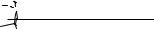
3. See the inset drawing. Cut the plastic tie near |
3 |
|
|
|
|
the Upright Wire (87). |
|
|
|
|
|
|
|
|
|
|
|
Attach a Wheel (96) to the Base (95) with the |
|
|
Plastic Tie |
|
|
3/8" x 2" Bolt (8) and the 3/8" Nut (10) that you |
|
|
|
|
89 |
removed in step 1. Do not overtighten the Nut; |
|
|
|
|
|
the Wheel must turn freely. |
|
|
8 |
|
|
Press a Base Cap (89) into the Base (95). |
|
|
|
|
|
|
|
|
|
|
|
|
|
|
96 |
95 |
Cut |
|
|
|
10 |
|
|
|
|
|
|
87 |
|
|
|
|
|
|
|
4. Identify the Right Upright (85), which is marked |
4 |
|
|
|
|
with a “Right” sticker. Hold the Right Upright |
|
|
|
85 |
|
near the Base (95) as shown. |
|
|
|
|
|
|
|
|
|
|
|
See the inset drawing. Tie the wire tie in the |
|
87 |
|
|
|
Right Upright (85) securely around the end of |
|
Wire Tie |
|
87 |
|
|
|
|
|||
the Upright Wire (87). Then, pull the other end |
|
|
|
|
|
of the wire tie until the Upright Wire is routed |
|
|
|
|
95 |
completely through the Right Upright. |
|
|
|
|
|
|
|
85 |
|
|
|
|
|
|
|
|
|
|
|
|
Wire |
|
|
|
87 |
|
Tie |
|
|
|
|
|
|
|
|
5. Hold the Right Upright (85) against the Base |
5 |
|
|
|
|
(95). Be careful not to pinch the Upright Wire |
|
|
|
7 |
|
|
|
|
|
||
(87). Insert two 3/8" x 4" Patch Bolts (7) and a |
|
|
85 |
3 |
|
3/8" x 1 1/2" Patch Bolt (3) with three 3/8" Star |
|
|
|
||
Washers (11) into the Right Upright. |
|
|
|
11 |
|
Tighten the 3/8" x 4" Patch Bolts (7) and the |
|
|
|
|
11 |
|
|
|
|
87 |
|
3/8" x 1 1/2" Patch Bolt (3) until the heads of the |
|
|
|
|
|
Patch Bolts touch the Right Upright (85); do not |
|
|
|
|
|
fully tighten the Patch Bolts yet. |
|
|
|
|
|
|
|
|
|
|
95 |
|
8 |
|
|
|
|

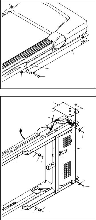
6. With the help of a second person, carefully tip |
6 |
|
|
|
|
the treadmill onto its right side. Partially fold the |
|
|
|
|
|
|
|
|
|
|
|
Frame (55) so that the treadmill is more stable; |
|
C |
|
|
|
do not fully fold the Frame yet. |
|
|
|
|
|
|
|
|
|
|
|
Remove and discard the two indicated bolts (B) |
B |
|
|
|
|
and the shipping bracket (C). |
|
|
|
|
|
Attach a Wheel (96) to the Base (95) with the |
89 |
|
|
|
|
3/8" x 2" Bolt (8) and the 3/8" Nut (10) that you |
|
|
|
|
|
|
|
|
8 |
|
|
removed in step 1. Do not overtighten the Nut; |
|
|
|
55 |
|
the Wheel must turn freely. |
|
|
|
|
|
Press a Base Cap (89) into the Base (95). |
|
|
|
|
|
|
|
95 |
|
|
|
|
|
|
96 |
10 |
|
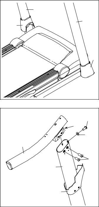
7. Hold the Left Upright (84) against the Base (95). |
7 |
|
|
|
|
Insert two 3/8" x 4" Patch Bolts (7) and a 3/8" x |
|
|
|
|
|
|
|
|
|
|
|
1 1/2" Patch Bolt (3) with three 3/8" Star |
|
|
|
|
|
Washers (11) into the Left Upright. |
|
3 |
|
|
|
Tighten the 3/8" x 4" Patch Bolts (7) and the |
7 |
|
84 |
|
|
11 |
|
|
|
||
3/8" x 1 1/2" Patch Bolt (3) until the heads of the |
|
|
|
|
|
Patch Bolts touch the Left Upright (84); do not |
11 |
|
|
|
|
fully tighten the Patch Bolts yet. |
|
|
|
|
|
With the help of a second person, tip the tread- |
|
|
|
|
|
mill so that the Base (95) is flat on the floor. |
|
|
|
|
|
|
95 |
|
|
|
|
9
8.Identify the Left Base Cover (88) and the Right Base Cover (91). Slide the Left Base Cover onto the Left Upright (84) and the Right Base Cover onto the Right Upright (85).
9.Identify the Left Upright Cover (80). Slide the Left Upright Cover onto the Left Upright (84). Identify the Left Handrail (82). Remove the tie from the bracket on the Left Handrail. If necessary, press the 5/16" Cage Nut (38) back into place.
Attach the Left Handrail (82) to the Left Upright (84) with two 5/16" x 1" Flat Head Patch Bolts (14), a 5/16" x 1" Patch Bolt (4), and a 5/16" Star Washer (13) as shown. Do not tighten the
Patch Bolts yet.
8 |
|
84 |
|
|
|
|
88 |
85 |
|
|
|
|
|
91 |
9 |
|
|
|
|
4 |
|
38 |
|
|
|
13 |
|
82 |
|
|
|
14 |
|
84 |
|
|
80 |
|
10
10.Slide the Right Upright Cover (86) onto the Right Upright (85). Remove the tie from the bracket on the Right Handrail (83). If necessary, press the 5/16" Cage Nut (38) back into place. Hold the Right Handrail (83) near the Right Upright (85). Insert the Upright Wire (87) through the bracket on the bottom of the Right Handrail. Pull the Upright Wire out of the end of the Right Handrail.
Attach the Right Handrail (83) to the Right Upright (85) with two 5/16" x 1" Flat Head Patch Bolts (14), a 5/16" x 1" Patch Bolt (4), and a 5/16" Star Washer (13) as shown. Do not tighten the Patch Bolts yet.
11.Set the console assembly face down on a soft surface to avoid scratching the console assembly. Remove the two #8 x 3/4" Screws (1). Lift off the Crossbar (107).
10 |
|
|
|
|
87 |
|
|
|
Bracket |
|
|
14 |
|
38 |
|
|
|
4 |
|
|
|
|
|
83 |
|
13 |
|
|
|
|
|
|
|
86 |
|
|
|
85 |
|
11 |
|
|
|
|
1 |
107 |
|
Console |
|
|
|
Assembly |
|
|
|
11
 Loading...