


Model No. PATL40906.0
Serial No.
Serial Number
Decal
QUESTIONS?
If you have questions, or if any parts are missing or damaged, PLEASE CONTACT OUR CUSTOMER SERVICE DEPARTMENT DIRECTLY.
Call toll-free:
800-830-7240
E-mail: service@goodfamily.cc
Goodfamily’s Web site:
www.goodfamily.cc
ICON’s Web site:
www.iconfitness.com
 CAUTION
Read all precautions and instructions in this manual before using this equipment. Save this manual for future reference.
USER'S MANUAL
Goodfamily is an authorized dealer of this treadmill in the territory of mainland China. This treadmill is designed and manufactured by ICON Health & Fitness, Inc.

TABLE OF CONTENTS
IMPORTANT PRECAUTIONS . . . . . . . . . . . . . . . . . . . . . . . . . . . . . . . . . . . . . . . . . . . . . . . . . . . . . . . . . . . . . . . .3 BEFORE YOU BEGIN . . . . . . . . . . . . . . . . . . . . . . . . . . . . . . . . . . . . . . . . . . . . . . . . . . . . . . . . . . . . . . . . . . . . . .5 ASSEMBLY . . . . . . . . . . . . . . . . . . . . . . . . . . . . . . . . . . . . . . . . . . . . . . . . . . . . . . . . . . . . . . . . . . . . . . . . . . . . . . .6 OPERATION AND ADJUSTMENT . . . . . . . . . . . . . . . . . . . . . . . . . . . . . . . . . . . . . . . . . . . . . . . . . . . . . . . . . . . .11 HOW TO FOLD AND MOVE THE TREADMILL . . . . . . . . . . . . . . . . . . . . . . . . . . . . . . . . . . . . . . . . . . . . . . . . . .24 TROUBLESHOOTING . . . . . . . . . . . . . . . . . . . . . . . . . . . . . . . . . . . . . . . . . . . . . . . . . . . . . . . . . . . . . . . . . . . . .26 CONDITIONING GUIDELINES . . . . . . . . . . . . . . . . . . . . . . . . . . . . . . . . . . . . . . . . . . . . . . . . . . . . . . . . . . . . . . .28 PART LIST . . . . . . . . . . . . . . . . . . . . . . . . . . . . . . . . . . . . . . . . . . . . . . . . . . . . . . . . . . . . . . . . . . . . . . . . . . . . . .31 EXPLODED DRAWING . . . . . . . . . . . . . . . . . . . . . . . . . . . . . . . . . . . . . . . . . . . . . . . . . . . . . . . . . . . . . . . . . . . .32 ORDERING REPLACEMENT PARTS . . . . . . . . . . . . . . . . . . . . . . . . . . . . . . . . . . . . . . . . . . . . . . . . . .Back Cover
PROFORM is a registered trademark of ICON IP, Inc.
2

IMPORTANT PRECAUTIONS
 WARNING: To reduce the risk of burns, fire, electric shock, or injury to persons, read the following important precautions and information before operating the treadmill.
1.It is the responsibility of the owner to ensure that all users of this treadmill are adequately informed of all warnings and precautions.
2.Use the treadmill only as described.
3.Place the treadmill on a level surface, with at least 2.5 m (8 ft.) of clearance behind it and 0.5 m (2 ft.) on each side. Do not place the treadmill on a surface that blocks any air openings. To protect the floor or carpet from damage, place a mat under the treadmill.
4.Keep the treadmill indoors, away from moisture and dust. Do not put the treadmill in a garage or covered patio, or near water.
5.Do not operate the treadmill where aerosol products are used or where oxygen is being administered.
6.Keep children under the age of 12 and pets away from the treadmill at all times.
7.The treadmill should be used only by persons weighing 136 kg (300 lbs.) or less.
8.Never allow more than one person on the treadmill at a time.
9.Wear appropriate exercise clothes when using the treadmill. Do not wear loose clothes that could become caught in the treadmill. Athletic support clothes are recommended for both men and women. Always wear athletic shoes; never use the treadmill with bare feet, wearing only stockings, or in sandals.
10.When connecting the power cord (see page 11), plug the power cord into an earthed circuit. No other appliance should be on the same circuit. When replacing the fuse, an ASTA approved BS1362 type should be fitted to the fuse carrier. A 13 amp fuse should be used.
11.Keep the power cord away from heated surfaces.
12.Never move the walking belt while the power is turned off. Do not operate the treadmill if the power cord or plug is damaged, or if the treadmill is not working properly. (See TROUBLESHOOTING on page 26 if the treadmill is not working properly.)
13.Read, understand, and test the emergency stop procedure before using the treadmill (see HOW TO TURN ON THE POWER on page 13).
14.Never start the treadmill while you are standing on the walking belt. Always hold the handrails while using the treadmill.
15.The treadmill is capable of high speeds. Adjust the speed in small increments to avoid sudden jumps in speed.
16.The pulse sensor is not a medical device. Various factors, including your movement, may affect the accuracy of heart rate readings. The sensor is intended only as an exercise aid in determining heart rate trends in general.
17.Never leave the treadmill unattended while it is running. Always remove the key and unplug the power cord when the treadmill is not in use.
18.Do not attempt to raise, lower, or move the treadmill until it is properly assembled. (See ASSEMBLY on page 6, and HOW TO FOLD AND MOVE THE TREADMILL on page 24.) You must be able to safely lift 20 kg (45 lbs.) to raise, lower, or move the treadmill.
19.When folding or moving the treadmill, make sure that the storage latch is fully engaged.
20.When using iFIT.com programs, an electronic “chirping” sound will alert you when the speed and/or incline of the treadmill is about to change. Always listen for the “chirp” and be prepared for speed and/or incline changes. In some instances, the speed and/or incline may change before the personal trainer describes the change.
3

21.When using iFIT.com programs, you can manually override the speed and incline settings by pressing the speed and incline buttons. However, when the next “chirp” is heard, the speed and/or incline will change to the next settings of the CD or video program.
22.Always remove iFIT.com CDs and videos from your CD player or VCR and disconnect your MP3 player when you are not using them.
23.Inspect and properly tighten all parts of the treadmill regularly.
24.Never insert any object into any opening.
25.DANGER: Always unplug the power cord immediately after use, before cleaning the treadmill, and before performing the maintenance and adjustment procedures described in this manual. Never remove the motor hood unless instructed to do so by an authorized service representative. Servicing other than the procedures in this manual should be performed by an authorized service representative only.
26.This treadmill is intended for in-home use only. Do not use this treadmill in a commercial, rental, or institutional setting.
 WARNING: Before beginning this or any exercise program, consult your physician. This is especially important for persons over the age of 35 or persons with pre-existing health problems. Read all instructions before using. ICON assumes no responsibility for personal injury or property damage sustained by or through the use of this product.
SAVE THESE INSTRUCTIONS
The decals shown at the right have been placed on the treadmill. If a decal is missing, or if it is illegible, call the telephone number on the front cover of this manual and order a free replacement decal. Apply the decal in the location shown. Note:
The decals are not shown at actual size.
4
BEFORE YOU BEGIN
Thank you for selecting the new PROFORM® 480 CX treadmill. The 480 CX treadmill combines advanced technology with innovative design to help you get the most from your exercise in the convenience of your home. And when you’re not exercising, the 480 CX treadmill can be folded up, requiring less than half the floor space of other treadmills.
For your benefit, read this manual carefully before using the treadmill. If you have questions after read-
ing this manual, please see the front cover of this manual. To help us assist you, please note the product model number and serial number before contacting us. The model number of the treadmill is PATL40906.0 The serial number can be found on a decal attached to the treadmill (see the front cover of this manual for the location).
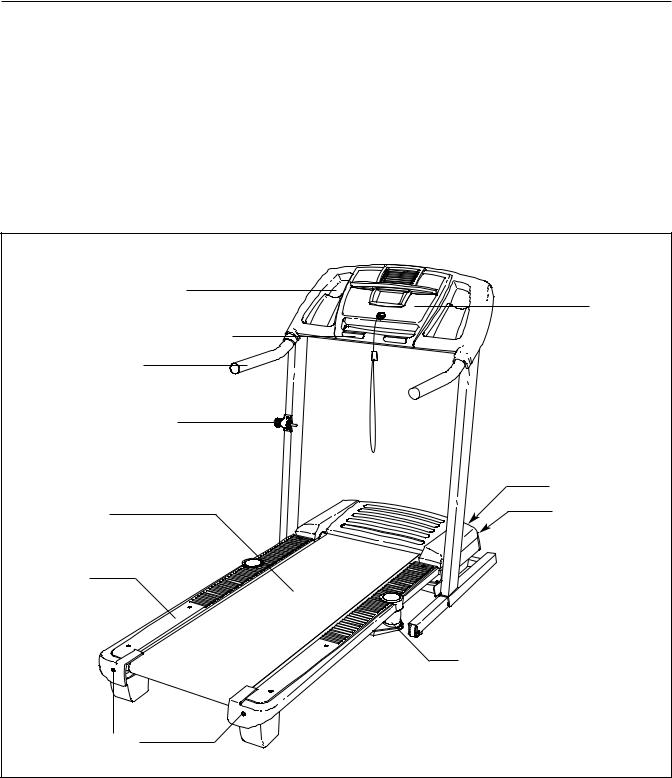
Before reading further, please familiarize yourself with the parts that are labeled in the drawing below.
Accessory Tray
Console
Handgrip Pulse Sensor


 Key/Clip
Handrail
Storage Latch
|
Circuit Breaker |
Walking Belt |
On/Off Switch |
Foot Rail |
|
Cushioned Walking Platform
for maximum exercise comfort
BACK
RIGHT SIDE
Rear Roller
Adjustment Bolts
5
ASSEMBLY
Assembly requires two persons. Set the treadmill in a cleared area and remove all packing materials; do not dispose of the packing materials until assembly is completed. Note: The underside of the walking belt is coated with high-performance lubricant. During shipping, a small amount of lubricant may be transferred to the top of the walking belt or the shipping carton. This is a normal condition and does not affect treadmill performance. If there is lubricant on top of the walking belt, wipe off the lubricant with a soft cloth and a mild, non-abrasive cleaner.
Assembly requires the included hex keys, |
your own phillips screwdriver |
, and your |
|
own rubber mallet |
. |
|
|
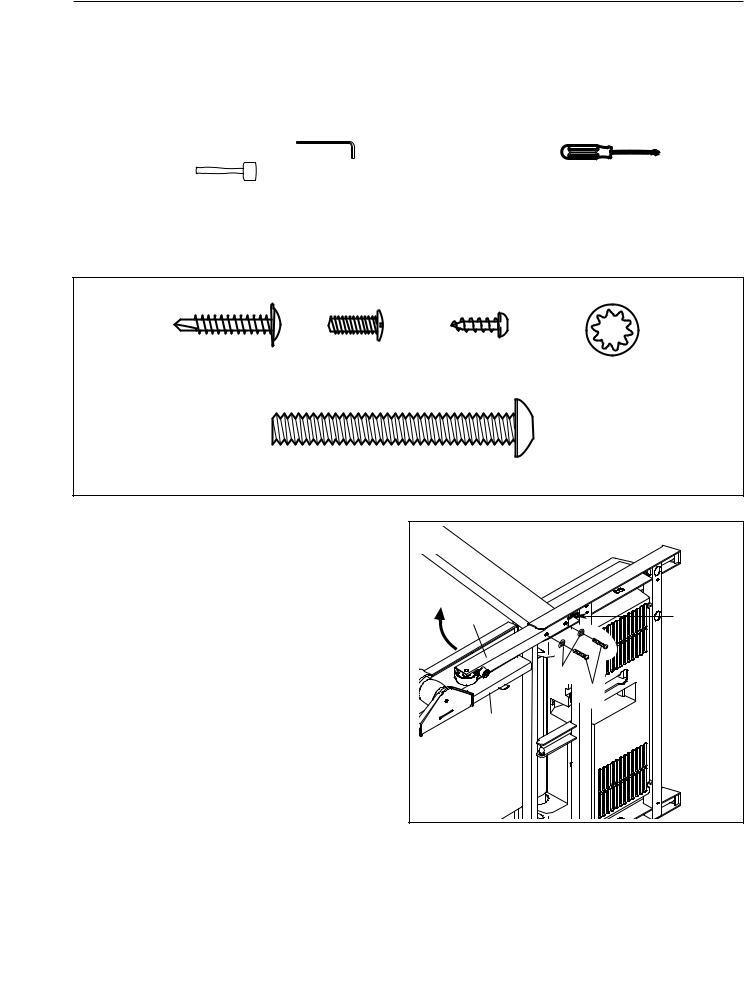
For help identifying the assembly hardware, see the drawings below. The number in parentheses below each drawing is the key number of the part, from the PART LIST on pages 30 and 31. The number following the parentheses is the quantity needed for assembly. Note: If a part is not in the parts bag, check to see if it has been pre-assembled. To avoid damaging plastic parts, do not use power tools for assembly.
1” Tek Screw |
Silver Ground |
Screw (3)–11 |
(22)–4 |
Screw (33)–1 |
Star Washer (8)–8 |
Handrail Bolt/Extension Leg Bolt (64)–8
1. Make sure that the power cord is unplugged. |
1 |
|
|
|
|
||
With the help of a second person, carefully tip |
|
|
|
the treadmill onto its left side as shown. Partially |
|
|
|
fold the Frame (58) so the treadmill is more sta- |
|
|
|
ble. Do not fully fold the treadmill until it is |
89 |
77 |
|
completely assembled. |
|||
|
|
||
Insert an Extension Leg (89) into the base of the |
|
|
|
Upright (84) as shown. Note: Be careful not to |
|
8 |
|
pinch the Upright Wire Harness (77) in the |
|
64 |
|
base of the Upright. To fully insert the |
|
|
|
Extension Leg, it may be necessary to tap on it |
|
58 |
|
with a mallet. Next, insert two Extension Leg |
|
|
|
Bolts (64) with Star Washers (8) into the bottom |
|
|
|
of the Extension Leg, and firmly tighten the |
|
|
|
Extension Leg Bolts. |
|
|
6

2. With the help of a second person, carefully tip |
2 |
|
|
|
the treadmill onto its right. Partially fold the |
|
|
|
|
|
|
|
|
|
Frame (58) so the treadmill is more stable. Do |
|
|
|
|
not fully fold the treadmill until it is com- |
|
|
|
|
pletely assembled. |
|
|
|
|
Insert the other Extension Leg (89) into the base |
|
|
|
89 |
|
|
|
|
|
of the Uprights (84) as shown. Next, insert two |
64 |
8 |
|
|
Extension Leg Bolts (64) into the bottom of the |
|
|
||
Extension Leg, and firmly tighten the Extension |
|
|
|
|
Leg Bolts. |
|
|
|
58 |
. |
|
|
|
|
|
|
|
|
|
3. Attach four Base Pads (82) to the base of the |
3 |
|
|
|
Uprights (84) with four 1” Tek Screws (22). |
|
|
|
|
|
|
|
|
|
With the help of a second person, carefully raise |
82 |
|
|
|
|
|
|
84 |
|
the treadmill so that all four Base Pads (82) are |
|
82 |
|
|
on the floor and the Upright (84) is in a vertical |
22 |
|
|
|
|
|
|
||
position. |
|
|
22 |
|
|
|
|
|
|
|
84 |
|
|
|
|
22 |
|
|
|
|
82 |
82 |
|
|
|
|
|
|
|
4. Have a second person hold the Handrail (20) |
4 |
|
|
|
near the Uprights (84). Insert the Upright Wire |
|
|
|
|
64 |
|
|
|
|
Harness (77) into the hole in the bottom of the |
|
|
|
|
Handrail and out of the top as shown. |
|
|
|
|
Next, set the Handrail (20) on the Uprights (84). |
8 |
|
|
|
|
20 |
|
|
|
Do not let the Upright Wire Harness (77) fall |
|
|
|
|
into the right Upright. |
|
|
64 |
8 |
|
|
|
|
|
Attach the Handrail (20) with four Handrail Bolts |
|
|
|
77 |
(64) and four Star Washers (8); start all four |
|
|
|
|
Handrail Bolts and then firmly tighten them. |
|
|
|
|
|
|
84 |
|
|
|
|
|
|
84 |
|
7 |
|
|
|

5.While a second person holds the console assembly near the Handrail (20), attach the ground wire to the indicated hole in the Handrail with a Ground Screw (33).
6.While the second person continues to hold the console assembly, locate the wire harness underneath the console assembly.
Connect the wire harness from the console assembly to the Upright Wire Harness (77). Make sure to connect the connectors properly (see the inset drawing). The connectors should slide together easily and snap into place. If the connectors do not slide together easily and snap into place, turn one connector and then try again. IF THE CONNECTORS ARE NOT CON-
NECTED PROPERLY, THE CONSOLE MAY BE DAMAGED WHEN THE POWER IS TURNED ON. Then, insert the connectors downward into the Handrail (20).
7.Set the console assembly on the Handrail (20).
Be careful to avoid pinching any of the wires. Make sure that the ground wire (see step 5) and the wire harness from the console assembly (see step 6) are in the indicated channel.
Hand tighten five Screws (3) into the Handrail (20) and the console assembly. Start all five
Screws, but do not tighten them yet. Do not put Screws into the two indicated holes.
5 |
|
|
|
Ground |
|
|
Wire |
|
|
33 |
|
|
Hole |
|
|
20 |
|
|
|
Console |
|
|
Assembly |
6 |
|
|
|
Wire |
77 |
Console |
77 |
|
Assembly |
|
|
|
20 |
|
7 |
|
|
Console Assembly
Channel
|
20 |
|
3 |
3 |
3 |
|
No Screws
8

8. Hand tighten four additional Screws (3) into the |
8 |
|
Console Assembly |
|
||
Handrail (20) and the console assembly. Then, |
|
|
||||
|
|
|
|
|
|
|
tighten all nine Screws used in step 7 and |
|
|
|
|
|
|
this step; do not overtighten the Screws. |
|
|
|
|
|
|
Plug in the power cord as described on page 11, |
|
|
|
|
|
|
and turn on the power as described on page 13. |
|
|
|
|
|
|
Note: The treadmill may automatically rise to the |
|
|
|
|
|
|
maximum incline level and then return to the |
|
|
|
|
|
|
minimum level. |
|
|
|
|
|
|
|
|
|
|
20 |
3 |
|
|
|
|
3 |
|
|
|
|
|
|
|
|
|
|
9. Attach the Latch Housing (73) to the left Upright |
9 |
|
|
|
|
|
(84) with two Screws (3). Make sure that the |
|
|
|
|
|
|
|
|
|
|
|
|
|
large hole in the Latch Housing is on the |
|
|
|
|
|
|
side shown. Do not overtighten the Screws. |
|
|
|
|
|
|
If the pin is not preassembled in the Latch |
|
|
|
|
84 |
|
Housing (73), remove the knob from the pin. |
|
|
73 |
|
|
|
Make sure that the collar and the spring are on |
|
|
|
|
|
|
|
|
|
|
|
|
|
the pin as shown. Insert the pin into the Latch |
|
|
|
|
|
|
Housing, and tighten the knob back onto the pin. |
Knob |
|
|
|
Spring |
|
|
|
|
|
|
|
|
|
|
3 |
Large |
|
|
|
|
|
|
|
|
|
|
|
|
|
Hole |
|
|
|
|
|
|
|
|
Collar |
|
|
|
|
|
|
Pin |
|
10.Place the treadmill in the storage position (see |
10 |
|
|
|
58 |
|
HOW TO FOLD AND MOVE THE TREADMILL |
|
|
|
|
||
|
|
|
|
|
|
|
on page 24). |
|
|
|
|
|
|
Next, place the cylinder end of the Shock (92) |
|
|
|
|
|
25 |
|
|
|
|
|
|
|
near the bracket on the base of the Uprights |
|
|
84 |
|
|
|
(84). |
|
|
|
|
|
|
|
|
|
25 |
|
|
|
|
|
|
|
|
|
|
See the two small inset drawings. Using your fin- |
|
|
92 |
|
Bracket |
|
gernail or the end of a screwdriver, press on the |
|
|
|
|
25 |
|
|
|
|
|
|
||
end of the Shock Pin (25) to loosen it from the |
|
|
|
|
Cylinder |
|
Shock (92). Next, rotate the Shock Pin and pull it |
|
|
|
|
|
|
|
|
|
|
|
|
|
out of the Shock. Be careful to avoid losing |
|
|
|
|
|
|
the Shock Pin. |
10a |
|
|
|
|
|
|
|
|
|
|
|
|
See drawing 10a. Press the cylinder end of the |
|
|
|
|
|
|
Shock (92) onto the ball on the bracket. Next, in- |
|
|
|
|
|
|
sert the end of the Shock Pin (25) through two of |
|
|
25 |
|
|
|
the small holes in the end of the Shock. Then, |
|
|
|
|
|
|
rotate the Shock Pin until it clips onto the Shock. |
|
|
92 |
|
Bracket |
|
|
|
|
|
|
||
|
|
|
|
|
|
|
|
9 |
|
|
|
|
|
11.Raise the Shock (92) to a vertical position. |
11 |
|
Remove the Shock Pin (25) from the raised end |
58 |
|
of the Shock as described in step 6. If neces- |
Bracket |
|
sary, rotate the Shock to align the end of the |
|
|
|
|
|
Shock with the ball on the bracket on the Frame |
|
|
(58). |
|
|
|
25 |
|
Next, press the Incline increase and decrease |
|
92 |
buttons until the ball on the bracket is aligned |
|
|
with end of the Shock (92). Then, press the end |
|
|
of the Shock onto the ball. Note: It may be nec- |
|
|
essary to press the end of the Shock onto the |
|
|
ball while the Frame is moving. |
11a |
|
|
|
|
See drawing 11a. Insert the Shock Pin (25) into |
|
|
the two indicated small holes in the end of the |
|
|
Shock (92). Then, rotate the Shock Pin until it |
Holes |
|
clips onto the Shock. Note: Extra Shock Pins are |
|
|
|
|
|
included. |
|
|
Press the Incline decrease button until the |
25 |
92 |
|
||
|
|
|
treadmill is at the lowest incline level. Then, |
|
|
unplug the power cord and lower the treadmill |
|
|
Frame (58) to the floor. |
|
|
12.Make sure that all parts are properly tightened before you use the treadmill. Note: Extra hardware may be included. Keep the included hex keys in a secure place; the large hex key is used to adjust the walking belt (see page 27). To protect the floor or carpet, place a mat under the treadmill.
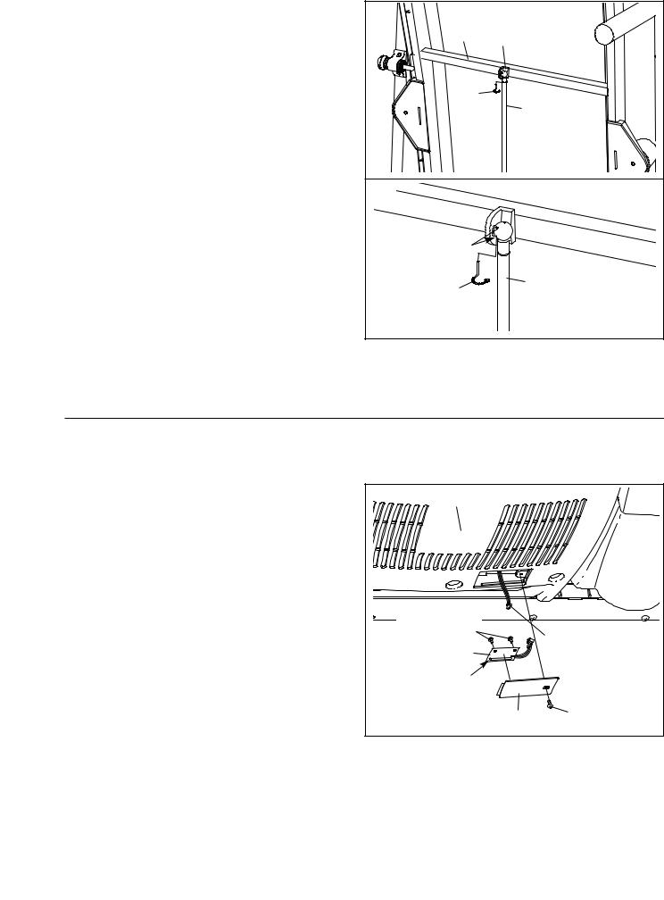
If you purchase the optional chest pulse sensor (see page 23), follow the steps below to install the receiver included with the chest pulse sensor.
1.Remove the key from the console and unplug the power cord.
Remove the Screw (3) and the Access Door (76) from the back of the Console Base (85).
2.Connect the wire on the receiver (A) to the indicated wire extending from the Console Base (85). Hold the receiver so the small cylinder is oriented as shown and is facing the Console Base. Attach the receiver to the plastic posts on the Access Door (76) with the two included small screws.
3.Make sure that no wires are pinched. Reattach the Access Door (76) with the Screw (3). Discard the other wires included with the receiver.
85 |
|
Small Screws |
|
A |
Wire |
|
|
Small |
|
Cylinder |
|
76 |
3 |
10
OPERATION AND ADJUSTMENT
THE PRE-LUBRICATED WALKING BELT
Your treadmill features a walking belt coated with high-performance lubricant. IMPORTANT: Never apply silicone spray or other substances to the walking belt or the walking platform. Such substances will deteriorate the walking belt and cause excessive wear.
HOW TO PLUG IN THE POWER CORD
This product must be earthed. If it should malfunction or break down, earthing provides a path of least resistance for electric current to reduce the risk of electric shock. This product is equipped with a power cord having an equipment-earthing conductor and an earthing plug. Important: If the power cord is damaged, it must be replaced with a manufacturer-recommended power cord.
See drawing 1. Plug the indicated end of the power cord into the socket on the treadmill.
See drawing 2. Plug the power cord into an appropriate outlet that is properly installed and earthed in accordance with all local codes and ordinances. Important: The treadmill is not compatible with
GFCI-equipped outlets.
1
Socket on Treadmill
Power
Cord
2
Outlet
 DANGER: Improper connection of the equipment-earthing conductor can result in an increased risk of electric shock. Check with a qualified electrician or serviceman if you are in doubt as to whether the product is properly earthed. Do not modify the plug provided with the product—if it will not fit the outlet, have a proper outlet installed by a qualified electrician.
11
 Loading...