


 Loading...
M O N I T O R / D E F I B R I L L A T O R
H E A R TS TA R T M R x
S e r v i c e M a n u a l
M 3 5 3 5 A
M 3 5 3 6 A

About This Edition
Edition 4
Printed in the USA
Publication number M3535-90900
The information in this document applies to the HeartStart MRx product version indicated below. This information is subject to change without notice.
Philips shall not be liable for errors contained herein or for incidental or consequential damages in connection with the furnishing, performance, or use of this material.
Edition History
Edition |
Product Version |
Print Date |
|
|
|
1 |
A.00/A.01 |
December, 2003 |
|
|
|
2 |
A.02 and earlier |
June, 2004 |
|
|
|
3 |
B.03 and earlier |
November, 2004 |
|
|
|
4 |
B.xx and earlier |
January, 2005 |
|
|
|
Copyright
Copyright © 2005
Koninklijke Philips Electronics N.V.
All rights are reserved. Permission is granted to copy and distribute this document for your organization’s internal educational use. Reproduction and/or distribution outside your organization in whole or in part is prohibited without the prior written consent of the copyright holder.
SMART Biphasic is a registered trademark of Philips.
FilterLine is a registered trademark of Oridion Medical Ltd.
Use of supplies or accessories other than those recommended by Philips may compromise product performance.
THIS PRODUCT IS NOT INTENDED FOR HOME USE.
IN THE U.S., FEDERAL LAW RESTRICTS THIS DEVICE TO SALE ON OR BY THE ORDER OF A PHYSICIAN.
Notice
Medical Device Directive
The HeartStart MRx complies with the requirements of the Medical Device Directive 93/42/EEC and carries the 
 0123 mark accordingly.
Manufacturer
Philips Medical Systems
3000 Minuteman Road
Andover, MA USA 01810-1099
(978) 687-1501
Authorized EU-representative:
Philips Medizin Systeme Böblingen GmbH
Hewlett Packard Str. 2
71034 Böblingen
Germany
Canada EMC:ICES-001
Warning
Radio frequency (RF) interference from nearby transmitting devices may degrade the performance of the HeartStart MRx. Electromagnetic compatibility with surrounding devices should be assessed prior to using the monitor/defibrillator.
i

Conventions Used in This Manual
This Service Manual contains the following conventions:
WARNING Warning statements describe conditions or actions that can result in personal injury or loss of life.
CAUTION Caution statements describe conditions or actions that can result in damage to the equipment or loss of data.
NOTE Notes contain additional information on usage.
TIP Tips provide hands-on insight into servicing this product.
TEXT |
represents messages that appear on the screen |
[Softkey] |
represents softkey labels that appear on the screen above or below the |
|
button to which they correspond. |
On-line viewing only
Hypertext |
represents hypertext links, which will display as blue; click on |
|
the blue link to go to that destination, then click on |
|
the blue destination to return. |
Abbreviations
Name |
Abbreviation |
HeartStart MRx Monitor/Defibrillator |
monitor/defibrillator |
|
device |
Noninvasive Blood Pressure |
NBP |
End-tidal carbon dioxide |
EtCO2 |
Carbon dioxide |
CO2 |
Pulse Oximetry |
SpO2 |
ii

Table of Contents
1 Introduction |
1 |
Who Should Use This Manual |
1 |
Overview |
1 |
Features and Capabilities |
2 |
Tour of the Device |
3 |
Right Side |
4 |
Left Side |
5 |
Rear |
6 |
Top |
7 |
General Service Information |
8 |
Installation |
8 |
Display Menus |
8 |
Passwords |
8 |
Upgrades |
8 |
Preventive Maintenance |
8 |
Repair Philosophy |
9 |
Accessing Service Mode |
10 |
Navigating in Service Mode |
11 |
Service Mode Functions |
12 |
Other Resources |
16 |
2 Maintenance |
17 |
|
|
Overview |
17 |
Maintenance Tools and Equipment |
18 |
Checking the NBP Module |
19 |
NBP |
19 |
Checking the CO2 Module |
23 |
CO2 |
23 |
3 Troubleshooting |
33 |
|
|
Overview |
33 |
Troubleshooting Tools and Equipment |
34 |
Obtaining Replacement Parts |
34 |
Ready For Use Indicator |
35 |
Automated Tests |
36 |
Automated Test Summary |
36 |
iii

Operational Check |
39 |
Operational Check Report |
43 |
Operational Check Summary |
44 |
Service Mode Tests |
44 |
Troubleshooting Methodology |
45 |
Troubleshooting Flowcharts |
47 |
Troubleshooting Tables |
53 |
Audio Tones |
54 |
Status Log Errors |
55 |
Startup Errors |
62 |
General Problems |
63 |
ECG Monitoring Problems |
64 |
NBP Monitoring Problems |
66 |
SpO2 Monitoring Problems |
67 |
CO2 Monitoring Problems |
68 |
Defibrillation Problems |
70 |
Pacing Problems |
73 |
Printing Problems |
74 |
Display Problems |
75 |
Audio Problems |
75 |
Controls Problems |
76 |
Internal Memory Problems |
77 |
External Data Card Problems |
77 |
4 Repair |
79 |
|
|
Overview |
79 |
Who Should Perform Repairs |
80 |
Repair Philosophy |
80 |
Calling for Service |
81 |
Repair Notes |
82 |
Safety Precautions |
82 |
Flex Circuit Connections |
82 |
Flex Circuit Handling |
83 |
Internal Connections |
83 |
Cable and Assembly Placement |
83 |
Device Reassembly |
83 |
Disposal |
84 |
Disposing of Empty Calibration Gas Cylinders |
84 |
Repair Tools and Equipment |
85 |
Key Components |
85 |
iv

External Assemblies |
86 |
Accessory Pouches |
87 |
Bedrail Hook Mount |
89 |
Therapy Knob |
90 |
Labels |
91 |
Printer Assembly |
93 |
Paddle Tray |
95 |
Paddle Tray 50 ohm Load Resistor |
98 |
Handle and Cap Plate |
100 |
Opening the case |
102 |
Discharge the Power Supply Capacitors |
102 |
Separate the Case |
102 |
Discharge the Therapy Capacitor |
105 |
Disconnect the Case Halves |
106 |
Internal Assemblies - Front Case |
107 |
Overview of Front Case |
108 |
PCMCIA Hole Plug |
109 |
Speaker and Microphone Assembly |
111 |
Internal Memory Card |
113 |
SpO2 PCA |
115 |
Measurement Module Panel |
117 |
Therapy Switch |
119 |
Fan Assembly |
121 |
Processor PCA |
123 |
Clock Battery |
132 |
Printer Connector PCA |
133 |
Display Assembly |
135 |
Ready For Use Indicator |
138 |
Front Panel Buttons |
140 |
Front Case Assembly |
141 |
Internal Assemblies - Rear Case |
144 |
Overview of Rear Case |
145 |
Therapy Capacitor |
146 |
Power PCA |
148 |
NBP and CO2 Module Tray |
152 |
Therapy PCA |
154 |
Therapy Port |
158 |
NBP Module |
160 |
CO2 Module |
162 |
CO2 Compartment Door |
167 |
Battery Connector PCA |
169 |
Rear Case Assembly |
174 |
Closing the case |
176 |
v

5 Performance Verification |
179 |
Overview |
179 |
Required Testing Levels |
180 |
External Repairs/Replacements |
180 |
Printer Replacement |
181 |
Internal Repairs |
181 |
Verification Test Equipment |
182 |
Test and Inspection Matrix |
184 |
Performance Verification Procedures |
190 |
Visual Inspection |
191 |
Service Mode Tests |
192 |
Functional Checks |
200 |
Safety Tests |
208 |
6 Parts and Accessories |
211 |
|
|
Overview |
211 |
Parts and Accessories Notes |
212 |
Ordering Replacement Parts |
212 |
Ordering Supplies and Accessories |
212 |
Key Component Tracking |
212 |
Replacement Parts |
213 |
Electrical Assemblies |
214 |
Processor PCA |
214 |
Other Replacement PCAs |
215 |
Other Electrical Assemblies |
216 |
Individual Electrical Parts |
216 |
External Electrical Components |
217 |
Internal Cables |
218 |
Paddles |
219 |
Mechanical Assemblies |
220 |
Replacement Mechanical Assemblies |
220 |
Individual Mechanical Parts |
221 |
Labels |
222 |
Instruction Label Sets |
222 |
Hazardous Shock Warning Label Set |
223 |
Branding Label Set |
223 |
Speaker Label Set |
223 |
Connector Label Set |
223 |
Supplies and Accessories |
224 |
Key Components |
229 |
vi

7 Theory of Operation |
233 |
Overview |
233 |
Schematic Diagrams |
235 |
System Level Interconnections |
236 |
Signal and Data Flow |
237 |
ECG Signal Flow |
238 |
Functional Descriptions |
239 |
Processor PCA |
239 |
Therapy PCA |
240 |
Power PCA |
240 |
Battery Connector PCA |
240 |
Power/Batteries |
240 |
Display Assembly |
241 |
Indicators |
242 |
RFU Indicator |
242 |
Front Panel Buttons |
242 |
Therapy Knob |
242 |
Paddle Indicators and Controls |
242 |
Printer Assembly and Printer Connector PCA |
243 |
ECG Monitoring Functions |
243 |
Defibrillation |
244 |
Transcutaneous Pacing |
246 |
Audio |
246 |
Data Storage |
247 |
Clock Backup Battery |
247 |
NBP Module |
247 |
SpO2 PCA |
247 |
CO2 Module |
248 |
vii
8 Specifications and Safety |
249 |
Specifications |
249 |
General |
249 |
Defibrillator |
249 |
ECG and Arrhythmia Monitoring |
252 |
Display |
254 |
Battery |
254 |
Thermal Array Printer |
255 |
Noninvasive Pacing |
255 |
SpO2 Pulse Oximetry |
256 |
NBP |
256 |
EtCO2 |
257 |
AwRR |
258 |
Calibration Gas for CO2 Measurement System |
259 |
12-Lead ECG |
259 |
Patient Data Storage |
259 |
Environmental (M3535A) |
259 |
Environmental (M3536A) |
261 |
Symbol Definitions |
263 |
Safety Considerations |
266 |
General |
266 |
Defibrillation |
268 |
Battery |
268 |
Electromagnetic Compatibility |
270 |
Reducing Electromagnetic Interference |
270 |
Restrictions for Use |
270 |
Emissions and Immunity |
270 |
Guidance and Manufacturer’s Declaration |
271 |
Waveforms |
278 |
1 Index |
283 |
|
|
1
Introduction
This Service Manual provides the information needed to successfully service the M3535A/M3536A HeartStart MRx monitor/defibrillator. This manual provides you with information on troubleshooting, repairing, and performance verification and safety testing of the monitor/defibrillator. There is also information on the theory of operation, maintenance procedures, and ordering parts and supplies.
Who Should Use This Manual
The intended users of this manual are technical personnel who have been trained in the safe and proper servicing of the HeartStart MRx. To assist in training, the Service Training video
(M3535-89300 NTSC, M3535-89310 PAL) is available.
Overview
In this chapter, you’ll find general information that you should know before servicing the HeartStart MRx. Detailed information regarding controls, operation, and capabilities of the device can be found in the Instructions for Use that was shipped with the product. The Instructions for Use also provides information on setting up the device and regular maintenance procedures, such as performing operational checks and battery maintenance. We recommend you review the Instructions for Use before servicing this device. This Service Manual assumes you are familiar with the controls and with basic operations.
This chapter is organized into the following sections:
Topic |
Page |
Features and Capabilities |
2 |
Tour of the Device |
3 |
General Service Information |
8 |
Accessing Service Mode |
10 |
Other Resources |
16 |
1

1 Introduction |
Features and Capabilities |
Features and Capabilities
The HeartStart MRx is a lightweight, portable, monitor/defibrillator. It provides four modes of operation, Monitor, Manual Defib, AED, and Pacer (optional).
In Monitor Mode you can monitor up to four ECG waveforms, acquired through a 3-, 5-, or 10-lead ECG set or multifunction electrode pads. Optional monitoring of pulse oximetry (SpO2 ), noninvasive blood pressure (NBP), and carbon dioxide (EtCO2) are also available. Measurements from these parameters are presented on the display and alarms are available to alert you to changes in the patient’s condition.
Monitor Mode also provides an optional 12-Lead ECG function, enabling you to preview, acquire, store, and print 12-lead ECG reports, with or without analysis/interpretation.
Manual Defib Mode offers simple, 3-step defibrillation. You analyze the patient’s ECG and, if appropriate: 1) select an energy setting, 2) charge, and 3) deliver the shock. Defibrillation may be performed using paddles or multifunction electrode pads. Manual Defib Mode also allows you to perform synchronized cardioversion and internal defibrillation.
In AED Mode, the HeartStart MRx analyzes the patient’s ECG and determines whether a shock is advised. Voice prompts guide you through the 3-step defibrillation process, providing easy-to-follow instructions and patient information. Voice prompts are reinforced by messages that appear on the display.
Both Manual Defib and AED Mode incorporate the Philips’ low energy SMART Biphasic waveform for defibrillation.
Optional Pacer Mode offers noninvasive transcutaneous pacing therapy. Pace pulses are delivered through multifunction electrode pads, using a monophasic waveform.
The HeartStart MRx is powered by rechargeable lithium ion batteries. Available battery power is easily determined by viewing the convenient battery power indicators located on the device display or by checking the indicators on the battery itself. Additionally, an external AC or DC power supply may be applied as a secondary power source and for continual battery charging.
The HeartStart MRx performs Automated Tests on a regular basis. The status of the device’s critical functions are reported to the Ready For Use (RFU) indicator. Prominently displayed, the RFU indicator communicates the status of your device, letting you know if it is operating correctly, needs attention, or is unable to deliver therapy. In addition, performing the specified Operational Check ensures that the HeartStart MRx is functioning properly.
The HeartStart MRx automatically stores critical event data in its internal memory, such as Event Summaries and 12-Lead Reports. The HeartStart MRx also enables you to copy data and event information on an optional external data card for downloading to Philips’ data management solution, HeartStart Event Review Pro.
The HeartStart MRx is highly configurable to better meet the needs of diverse users. Be sure to familiarize yourself with the device’s configuration before using the HeartStart MRx.
2

Tour of the Device |
1 Introduction |
Tour of the Device
This section gives an overview of the outside of the device.
Figure 1 Front view
External Power Indicator |
Synchronized Cardioversion |
|
(Sync) button |
Ready For Use (RFU)
 Indicator
Mark Event |
Therapy Knob |
|
button |
||
|
Lead Select button 
|
|
c |
|
n |
|
y |
|
|
S |
|
|
|
|
|
|
ib |
|
|
|
|
f |
|
|
|
D |
e |
|
a |
l |
50 |
|
u |
|
|||
|
|
|||
n |
|
|
|
|
a |
|
|
30 |
|
M |
|
|
||
|
|
|
|
|
|
|
|
20 |
|
|
|
Adult |
|
120 |
Dose |
100 |
150 |
|
70 |
|
170 |
200
Select 1 Energy
CHARGE button
SHOCK button
|
15 |
|
Display |
1-10 |
|
Pacer |
On Off On |
|
|
Monitor |
AED |
Alarm Pause button Event Summary Soft keys (4 total) Navigation buttons button
Charge
 2
2
 Printer
Shock
 3
3
Printer door
 Printer door latch
Print button
 Speaker
Menu Select button
3
1 Introduction |
Tour of the Device |
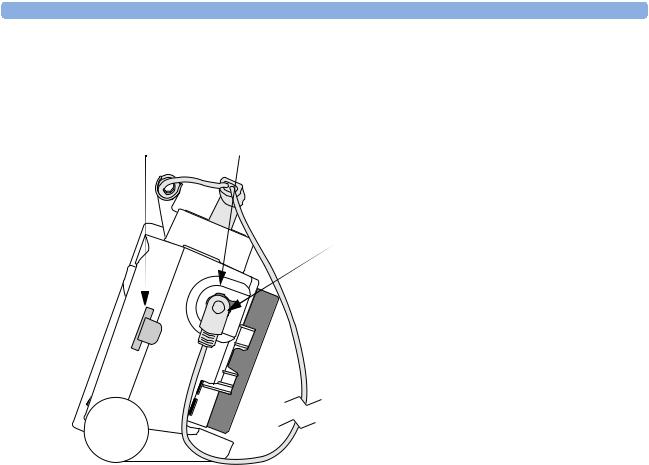
Right Side
Figure 2 Right side view
Data Card |
Therapy port (behind connector) |
Therapy connector
4
Tour of the Device |
1 Introduction |
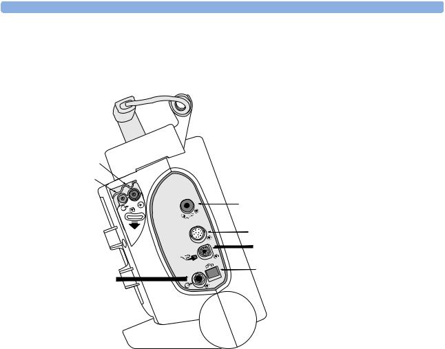
Left Side
Figure 3 Left side view
CO2 Inlet Port
CO2 Outlet Port
|
|
|
|
|
1 |
CO2 |
|
|
|
|
|
|
|
|
|
|
2 |
|
|
|
|
|
™ |
|
|
|
|
|
m |
|
|
|
|
e |
a |
|
|
|
t r |
|
|
|
|
s |
|
|
|
|
ro |
|
|
|
|
ic |
|
|
|
ECG |
|
|
|
|
|
||
M |
|
|
|
|
|
ECG Out (Sync) |
ECG |
Jack |
|
NBP Port
ECG Port
SpO2 Port
RJ11 Telephone
Jack
5
1 Introduction |
Tour of the Device |
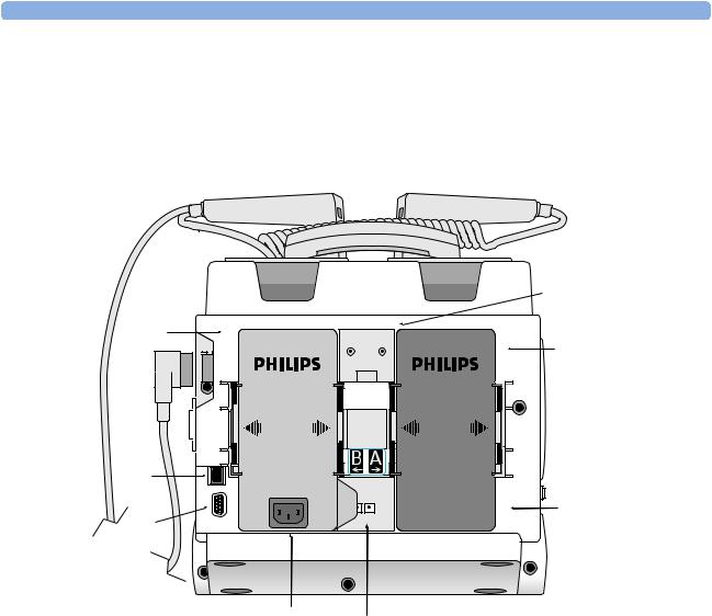
Rear
Figure 4 Rear view
Battery/AC
Compartment B
LAN Connection |
Bed Rail Hook Mount
Battery
Compartment A
Battery
RS 232 Serial Port
AC Power Module
DC Power Input
NOTE The LAN port is for factory use only.
6

Tour of the Device |
1 Introduction |
Top
Figure 5 Top view.
Top access panel
PCMCIA card slots
Internal memory card slot
7

1 Introduction |
General Service Information |
General Service Information
Keep the following points in mind when servicing this product.
Installation
The HeartStart MRx does not require installation. The Instructions for Use describes the setup required before placing the device into service, as well as configuration options. All setup activities are designed to be performed by personnel trained in the proper operation of the product. To obtain a copy of the Instructions for Use and other MRx documentation go to: www.medical.philips.com/goto/productdocumentation.
Display Menus
To display a menu, press the Menu Select  button. Then use the up
  or down
  Navigation buttons to scroll through the available choices until the desired selection is highlighted. To activate the selection, press the Menu Select button. Press Exit to close the menu without activating a selection.
Passwords
In order to access different modes within the monitor/defibrillator, a password is required. The passwords are listed below:
•Service Mode: 27689
•Configuration Mode: 387466
Upgrades
Upgrades are available to add specific functionality to the device after purchase. These upgrades are:
•M3530A SpO2
•M3531A NBP
•M3532A CO2
•M3533A Pacing
•M3534A 12-Lead
Option B02 - 12-lead acquisition Option B03 - 12-lead transmission Option B04 - 75 mm printer
•M4760A Handle and Cap Plate
•M5527A External paddles
•M4765A Hardware Upgrade Option B01 - Version B hardware that supports 12-lead transmission Consult your sales representative, dealer, or distributor for the latest details.
Preventive Maintenance
Preventive maintenance and periodic operational checks are intended to be performed by the user. Both topics are covered in the Maintenance chapter of the Instructions for Use.
The Maintenance chapter of this manual provides procedures for the CO2 and NBP calibration procedures, which are intended to be performed by qualified service personnel.
8

General Service Information |
1 Introduction |
Repair Philosophy
Monitor/Defibrillator
The repair philosophy of the HeartStart MRx is subassembly replacement. Examples of subassemblies are the printer, the Processor Printed Circuit Assembly (PCA), Therapy PCA, and selected connectors and other items. Repairs that involve replacing components on a PCA are not supported.
CAUTION Individual component replacement should not be attempted. Component level repair is inadvisable due to the extensive use of surface mount technology and the high parts-density on the circuit boards. Unauthorized component replacement can impair performance of the HeartStart MRx.
WARNING Remove all power sources (AC, battery, DC) before opening the device. Failure to do so may allow the device to charge without warning and could result in serious injury or death.
Batteries
The M3538A Lithium Ion battery is rechargeable. The battery periodically requires a calibration. At the end of the battery’s useful life, it should be discarded and replaced. Refer to the Instructions for Use for additional information.
For information on ordering replacements, see "Ordering Supplies and Accessories" on page 212.
WARNING Never crush, penetrate or attempt to open lithium ion batteries. Never incinerate lithium ion batteries. High case temperatures resulting from abuse of the battery could cause physical injury. The electrolyte is highly flammable. Rupture of the battery pack may cause venting and flame.
CAUTION Due to their high energy density, lithium ion batteries can deliver significant power. Use care when working with or testing lithium ion batteries. Do not short circuit the terminals.
9

1 Introduction |
Accessing Service Mode |
Accessing Service Mode
CAUTION Be sure that the monitor/defibrillator is not connected to a patient when performing any function in Service Mode.
NOTE Make sure that you insert a battery charged to at least 20% into the device or connect external power when you are performing functions in Service Mode.
To access Service Mode:
1.Turn the Therapy Knob to Monitor.
2.Press the Menu Select button to display the Main menu.
3.Select Other.
4.From the Other menu select Service.
The message “Leaving Normal Operating Mode. Patient Monitoring is Off. To return to Normal Operating Mode, press the Exit Softkey.” appears.
5.Press the Menu Select button to acknowledge the message.
You are prompted to enter a password.
6.Enter the password (27689) by scrolling through the list until the desired number is highlighted.
7.Press the Menu Select button to activate each selection.
8.Select Done when you have entered all of the numbers.
10
Accessing Service Mode |
1 Introduction |
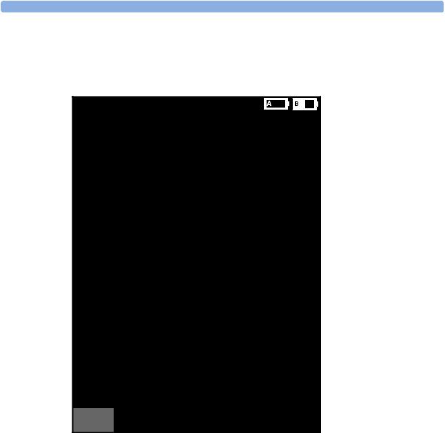
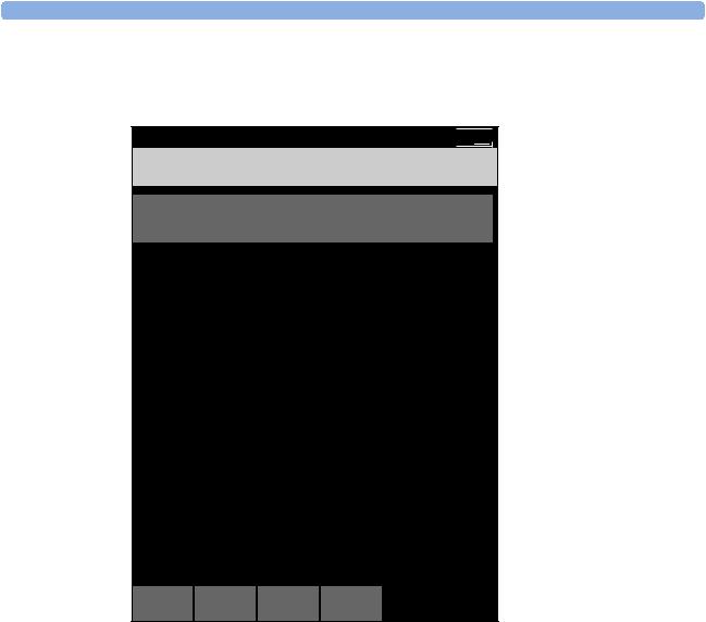
The Service Mode Main menu is displayed, as shown in Figure 6.
Figure 6 Service Mode Main Menu
02 Mar 2003 10:52 

Service . MAIN
|
Service |
|
Operational Check |
|
Status Log |
|
|
|
NBP |
|
|
|
CO2 |
|
Controls |
|
Printer |
|
|
Exit |
Device Info |
Service |
Software Upgrade |
Navigating in Service Mode
Service Mode uses the same navigation controls as normal operating mode:
•To select a menu item, use the Navigation buttons to highlight your choice, then select that choice by pressing the Menu Select button.
•To exit Service Mode and return to clinical mode, press the [Exit Service] soft key.
•To return to the Service Mode Main menu from any service screen press the [Main Service] soft key.
NOTE The device’s default configuration settings are restored when you return to clinical mode after exiting Service Mode.
11

1 Introduction |
Accessing Service Mode |
Service Mode Functions
You can perform a variety of service related activities from Service Mode, as follows:
•Run an Operational Check - See “Operational Check” on page 39.
•View, print and clear the Status log - See “Status Log Errors” on page 55.
•Perform maintenance on the NBP module - See “Checking the NBP Module” on page 19.
•Perform maintenance on the CO2 module - See “Checking the CO2 Module” on page 23.
•Run the Controls test - See “Controls Test” on page 193.
•Run the Printer test - See “Printer Test” on page 194.
•View information about the device, such as model number, serial number, options enabled on the device, and the device’s language - See “Device Info” on page 13. You also use the Device Info menu to enter the serial number and to enable options on the device after a Processor PCA repair. See “Entering the Serial Number and Enabling Options” on page 128 for more information.
NOTE You can print detailed information on board and module levels through the Print Device Info option, available in normal operating mode. See “Printing the Device Information” on page 16.
•Install software and change the device’s language using the Software Support Tool - See “Software Support Tool” on page 13.
12
Accessing Service Mode |
1 Introduction |
Device Info
To view information about the device:
1. From the Service Mode Main menu, select Device Info.
Figure 7 Device Info Screen
|
02 Mar 2003 10:52 |
Service . DEVICE INFO |
|
Model Number: |
M3536A |
Serial Number: |
US00100320 |
Options: |
SpO2, CO2, NBP |
Language: |
American English |
Main |
MENU |
Service |
|
Software Support Tool
To install software onto the device or to change the device’s language:
1.Be sure an AC power module or battery charged to at least 20% is in place.
2.Insert the Software Support Tool into the data card slot.
3.From the Service Mode Main menu, select Software Upgrade.
4.Select the appropriate product version.
5.Press the [Upgrade] soft key.
The software is installed on the device. This process takes a few minutes. While the software is being updated, progress messages are displayed and the [Main Service] soft key is disabled.
13
1 Introduction |
Accessing Service Mode |
NOTE Be careful not to interrupt the software installation process by removing the power source or turning the device off.
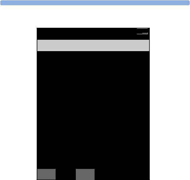
Figure 8 Software Upgrade Screen
02 Mar 2003 10:52 

Service . SOFTWARE UPGRADE
HeartStart MRx Version B.04.00 Upgrade: American English
Main |
Prev |
Next |
Upgrade |
Service |
Item |
Item |
6.When the software or language installation process is complete, turn the device off and on.
7.Run an Operational Check.
8.Review the Operational Check results to ensure all tests have passed.
See “Operational Check” on page 39.
9.Print the Device Info to ensure the product version or language is correct.
See “Printing the Device Information” on page 16.
14
Accessing Service Mode |
1 Introduction |
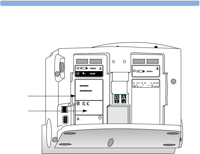
10.Affix the appropriate label found in the Software Support Tool kit to battery compartment B, as show in Figure 9. Additionally, make sure that the customer has the Instructions for Use (found on the User Documentation CD) that matches the product version.
Figure 9 Rear case labels
Primary label |
|
Product Version |
|
label |
B2.04.00 |
|
NOTE The label that you apply to the device is in the format Xx.xx. This is functionally equivalent to the X.xx Product Version that appears on the Device Info and Software Upgrade screens and the printed device information report. For example, product version B2.04 is functionally equivalent to B.04.
15

1 Introduction |
Other Resources |
Printing the Device Information
You can print detailed information on product versions, and board and module levels from the Print Device Info menu option. This option is available from the Other menu in clinical modes.
To print the device information:
1.Be sure a battery charged to at least 20% is in place, or that external power is connected.
2.Turn the Therapy Knob to Monitor.
3.Press the Menu Select button to access the Main menu.
4.From the Main menu, select Other.
5.From the Other menu, select Print Device Info.
Detailed information about the device is printed.
Other Resources
For additional information on the HeartStart MRx, refer to the following Learning Products:
•HeartStart MRx Instructions for Use (M3535-91900)
•HeartStart MRx Service Training Video (M3535-89300 NTSC, M3535-89310 PAL)
•HeartStart MRx Lithium Ion Battery Characteristics and Care Application Note (M3535-91930)
Other documentation can be found on the Philips website at:
www.medical.philips.com/goto/productdocumentation.
16

2
Maintenance
This chapter describes how to perform routine maintenance on the HeartStart MRx monitor/defibrillator.
Overview
Most routine maintenance is performed by the user. This includes:
•Performing operational checks
•Replacing paper
•Charging and maintaining the lithium ion battery
•Cleaning
Refer to the Instructions for Use for detailed information on these maintenance procedures. Service personnel are responsible for the following routine maintenance:
•Yearly calibration (or every 10,000 cycles) of the Noninvasive Blood Pressure (NBP) module
•Yearly calibration (or every 4000 hours) of the End-tidal Carbon Dioxide (EtCO2) module This chapter provides the following information:
Topic |
Page |
Maintenance Tools and Equipment |
18 |
Checking the NBP Module |
19 |
Checking the CO2 Module |
23 |
17

2 Maintenance |
Maintenance Tools and Equipment |
Maintenance Tools and Equipment
You will need the following equipment to perform the yearly calibration procedures:
•Password to access Service Mode (27689)
•NBP
–manometer
–expansion chamber (volume 250 ml +/- 10%) or an NBP cuff can be used
NOTE If you are using an NBP cuff, make sure it is wrapped around a solid object.
•CO2
–calibration gases and regulator cal 1 gas 15210-64010 (5% CO2)
cal 2 gas 15210-64020 (10% CO2) cal gas flow regulator M2267A
–electronic flowmeter, M1026-60144
–Gas calibration equipment cal tube 13907A FilterLine set, M1920A
–local barometric pressure rating or reading received from a reliable local source (airport, regional weather station, or hospital weather station) which is located at the same altitude as the hospital or EMS service.
–calculator
NOTE In addition to the items listed above, the calibration procedures require tubing and connectors typically found in a biomedical engineering shop.
18

Checking the NBP Module |
2 Maintenance |
Checking the NBP Module
NBP
These instructions describe how to test the NBP measurement function. A complete test consists of the following activities, which are described in detail in this chapter.
NBP Check |
Page |
Setup |
19 |
Check the status displays |
20 |
Test the accuracy |
21 |
Test for leaks |
21 |
Test the linearity |
22 |
Calibrate the NBP Measurement |
22 |
Run an Operational Check |
22 |
Each of the procedures assumes the monitor/defibrillator, the manometer, and the expansion chamber are still set up as they were at the end of the previous test.
If all results are as described, the device passes that portion of the test. Return to the Service Mode Main menu by pressing the [Main Service] soft key.
If there is any failure, begin troubleshooting and repairing the device as needed. See “Troubleshooting” on page 33.
Setup
1Access the Service Mode Main menu as described in “Accessing Service Mode” on page 10.
2From the Service Mode Main menu, select NBP. The NBP Service screen is displayed.
19
2 Maintenance |
Checking the NBP Module |
NOTE You will hear a high-pitch tone when you access the NBP Service screen - this is normal operation.
Figure 10 NBP Service Screen
02 May 2003 10:52 

Service . NBP
Cycle Counter: |
50,010 |
Last Calibration: |
2 May 2004 |
Replacement recommended Calibration recommended
Pressure In Cuff: 23 mmHg
Main
Service Calibrate
Check the status displays
1.Check the cycle counter.
Check the number of measurement cycles shown on the screen. If the NBP module has executed more then 50,000 cycles, replacement is recommended. See “NBP Module” on page 160 for instructions on replacing the NBP module.
Following replacement, run the required Performance Verification and Safety Tests (see “Required Testing Levels” on page 180).
2.Check the calibration status.
If the screen indicates that calibration is recommended, perform all of the actions described in this chapter, beginning with "Test the accuracy".
The calibration status is automatically reset at the successful completion of a calibration.
20
Loading...