


Operating Instructions Bedienungsanleitung Instructions d’utilisation Istruzioni per l’uso Gebruiksaanwijzing Manual de instrucciones Brugsvejledning Driftsföreskrifter Bruksanvisning Käyttöohjeet
Cordless Impact Driver/Cordles Impact Wrench Akku-Schlagschrauber/Akku-Schlagschrauber
Perceuse à impact sans fil/Perceuse à impact sans fil Avvitatore ad impulsi senza fili/Avvitatore ad impulsi senza fili
Snoerloze slagschroevendraaier/Snoerloze slagschroevendraaier Destornillador de impacto inalámbrico/Destornillador de impacto inalámbrico Akku-slagboremaskine/Akku-slagboremaskine Sladdlös slagskruvdragare/Sladdlös slagskruvdragare Trådløs slagbormaskin/Trådløs slagbormaskin Langaton iskuruuviavain/Langaton iskuruuviavain
Model No: EY7546/EY7547 EY7550/EY7551
Before operating this unit, please read these instructions completely and save this manual for future use.
Vor Inbetriebnahme des Gerätes die Betriebsanleitung bitte gründlich durchlesen und diese Broschüre zum späteren Nachschlagen sorgfältig aufbewahren. Lire entièrement les instructions suivantes avant de faire fonctionner l’appareil et conserver ce mode d’emploi à des fins de consultation ultérieure. Prima di usare questa unità, leggere completamente queste istruzioni e conservare il manuale per usi futuri.
Lees deze gebruiksaanwijzing aandachtig door voor u het apparaat in gebruik neemt en bewaar de gebruiksaanwijzing voor eventuele naslag. Antes de usar este aparato por primera vez, lea todas las instrucciones de este manual y guarde el manual para poderlo consultar en el futuro. Gennemlæs denne betjeningsvejledning før brugen og gem den til fremtidig brug.
Läs igenom hela bruksanvisningen innan produkten tas i bruk. Spara bruksanvisningen för senare användning. Før enheten tas i bruk, vennligst les disse alle anvisningene og oppbevar bruksanvisningen for senere bruk. Lue ohjeet huolella ennen laitteen käyttöönottoa ja säilytä tämä käyttöohje tallessa tulevaa tarvetta varten.
|
|
|
|
EY7546_EY7547_EY7550_EY7551_EU.indb 1 |
2011-2-25 14:40:06 |
||
|
|
|
|

Index/Index/Index/Indice/Index/Indice/Indeks/Index/Indeks/Hakemisto/ |
||||||
Индекс/Індекс |
|
|
|
|
|
|
English: |
Page |
|
5 |
Español: |
Página |
57 |
Deutsch: |
Seite |
|
16 |
Dansk: |
Side |
68 |
Français: |
Page |
|
26 |
Svenska: |
Sid |
78 |
Italiano: |
Pagina |
|
37 |
Norsk: |
Side |
88 |
Nederlands: |
Bladzijde |
47 |
Suomi: |
Sivu |
98 |
|
FUNCTIONAL DESCRIPTION |
|
|
||||
FUNKTIONSBESCHREIBUNG |
|
|
||||
DESCRIPTION DES FONCTIONS |
|
|
||||
DESCRIZIONE DELLE FUNZIONI |
|
|
||||
FUNCTIEBESCHRIJVING |
|
|
||||
DESCRIPCIÓN FUNCIONAL |
|
|
||||
FUNKTIONSBESKRIVELSE |
|
|
||||
FUNKTIONSBESKRIVNING |
|
|
||||
FUNKSJONSBESKRIVELSE |
|
|
||||
TOIMINTOJEN KUVAUS |
|
|
||||
|
|
|
|
|
(A)′ |
|
|
|
|
(A) |
(B) |
|
|
|
|
(P) |
|
(C) |
|
|
(M) |
(N) (O) |
|
|
|
||
|
|
|
(J) |
(D) |
(Q) |
|
|
|
|
|
|
||
|
|
|
|
(E) |
|
|
|
|
|
(I) |
|
|
|
|
|
|
|
|
|
|
|
|
|
(H) |
|
|
|
(L) |
(K) |
|
(G) |
|
|
|
|
|
|
10.8 V ─ 28.8 V |
|
||
|
|
|
|
(F) |
|
|
|
|
|
|
|
|
(R) |
|
|
|
|
- 2 - |
|
|
EY7546_EY7547_EY7550_EY7551_EU.indb 2 |
|
|
|
|
2011-2-25 14:40:06 |
|
|
6.35 mm (1/4”) hex quick connect chuck |
|
Square drive (ball detent) |
|
6,35 mm (1/4”) Sechskant-Schnellaufspannfutter |
|
Vierkant-Werkzeugaufnahme (Kugelraste) |
|
Mandrin de connexion rapide hexagonal de 6,35 mm (1/4”) |
|
Mandrin |
|
Mandrino esagonale di collegamento rapido da 6,35 mm (1/4”) |
|
Mandrino |
(A) |
6,35 mm zeskantboorkop met snelkoppeling |
(A)’ |
Boorkop |
Mandril hexagonal de conexión rápida de 6,35 mm (1/4”) |
Portabroca |
||
|
6,35 mm (1/4”) hexagonal borepatron til hurtig tilslutning |
|
Borepatron |
|
Snabbchuck med 6,35 mm sexkantshylsa |
|
Fyrkantig drivbult (med kulspärr) |
|
6,35 mm (1/4”) hex hurtigtilkoplingschuck |
|
Chuck |
|
|
Kiinnityslaite |
|
|
6,35 mm (1/4”) kuusiopikaistukka |
|
|
|
|
|
|
|
|
|
|
|
Nose protector |
|
Forward/Reverse lever |
|
Frontabdeckung |
|
Vorwärts-/Rückwärtshebel |
|
Protection du bec |
|
Levier d’inversion marche avant/marche arrière |
|
Protezione frontale |
|
Leva di avanzamento/inversione |
(B) |
Neusbeschermer |
(C) |
Links/rechtsschakelaar |
Protector del morro |
Palanca de avance/marcha atrás |
||
|
Næsebeskytter |
|
Greb til forlæns/baglæns retning |
|
Nosskydd |
|
Riktningsomkopplare |
|
Nesebeskytter |
|
Forover-/bakoverbryter |
|
Kärjen suojus |
|
Eteenpäin/taaksepäin vipu |
|
Belt hook lock lever |
|
Belt hook |
|
Riemenhaken-Verriegelungshebel |
|
Riemenhaken |
|
Levier de verrouillage du crochet de ceinture |
|
Crochet de ceinture |
|
Leva di blocco gancio da cintura |
|
Gancio da cintura |
(D) |
Borghendel voor riemclip |
(E) |
Riemclip |
Palanca de bloqueo del gancho de cinturón |
Gancho del cinturón |
||
|
Låsehåndtag til bæltekrog |
|
Bæltekrog |
|
Låsknapp för bälteskrok |
|
Bälteskrok |
|
Låsespak for beltekrok |
|
Beltekrok |
|
Vyölenkin lukitusvipu |
|
Vyölenkki |
|
Alignment marks |
|
Battery pack release button |
|
Ausrichtmarkierungen |
|
Akku-Entriegelungsknopf |
|
Marques d’alignement |
|
Bouton de libération de batterie autonome |
|
Marcature allineamento |
|
Tasto di rilascio pacco batteria |
(F) |
Uitlijntekens |
(G) |
Accu-ontgrendeltoets |
Marcas de alineación |
Botón de liberación de batería |
||
|
Flugtemærker |
|
Udløserknap til batteripakning |
|
Anpassningsmärken |
|
Frigöringsknapp för batteri |
|
Opprettingsmerke |
|
Utløserknapp for batteripakke |
|
Sovitusmerkit |
|
Akkupaketin irrotuspainike |
|
Battery pack |
|
LED light |
|
Akku |
|
LED-Leuchte |
|
Batterie autonome |
|
Lumière DEL |
|
Pacco batteria |
|
Luce LED |
(H) |
Accu |
(I) |
LED-lampje |
Batería |
Luz indicadora |
||
|
Batteripakning |
|
LED-lys |
|
Batteri |
|
LED-ljus |
|
Batteripakke |
|
LED-lys |
|
Akku |
|
LED-valo |
|
Control panel |
|
LED light ON/OFF button |
|
Bedienfeld |
|
LED-Leuchten-EIN/AUS-Taste |
|
Panneau de commande |
|
Bouton Marche/Arrêt de la lumière DEL |
|
Pannello di controllo |
|
Tasto di accensione e spegnimento della luce LED |
(J) |
Bedieningspaneel |
(K) |
Aan/uit-toets (ON/OFF) voor LED-lampje |
Panel de control |
Botón ON/OFF de luz LED |
||
|
Kontrolpanel |
|
TÆND/SLUK-knap til LED-lys |
|
Kontrollpanel |
|
Strömbrytare för LED-ljus |
|
Kontrollpanel |
|
PÅ/AV-knapp for LED-lys |
|
Säätöpaneeli |
|
LED-valon kytkin/katkaisupainike |
- 3 -
|
|
|
|
EY7546_EY7547_EY7550_EY7551_EU.indb 3 |
2011-2-25 14:40:06 |
||
|
|
|
|
|
Impact power mode button |
|
Impact power mode display |
|
Schlagkraftmodus-Wahltaste |
|
Schlagkraftmodusanzeige |
|
Bouton du mode de puissance de percussion |
|
Affichage du mode de puissance de percussion |
|
Tasto modalità potenza impatto |
|
Display modalità potenza impatto |
(L) |
Slagkrachtfunctietoets |
(M) |
Slagkrachtfunctiedisplay |
Botón de modo de potencia de impacto |
Indicación de modo de potencia de impacto |
||
|
Slagkraftfunktionsknap |
|
Slagkraftfunktionsdisplay |
|
Slagkraftsväljare |
|
Slagkraftsindikering |
|
Knapp for slagstyrketype |
|
Fremviser av slagstyrketype |
|
Iskutehomuodon painike |
|
Iskutehomuodon merkkivalo |
|
|
|
|
|
Battery low warning lamp |
|
Overheat warning lamp (motor/battery) |
|
Akkuladungs-Warnlampe |
|
Überhitzungs-Warnlampe (Motor/Akku) |
|
Témoin d’avertissement de batterie basse |
|
Témoin d’avertissement de surchauffe (moteur/batterie) |
|
Spia avvertenza batteria scarica |
|
Spia avvertenza surriscaldamento (motore/batteria) |
(N) |
Waarschuwingslampje voor lage accuspanning |
(O) |
Oververhitting-waarschuwingslampje (motor/accu) |
Luz de aviso de baja carga de batería |
Luz de advertencia de sobrecalentamiento (motor/batería) |
||
|
Advarselslampes batterieffekt lav |
|
Advarselslamp til overophedning (motor/batteri) |
|
Varningslampa för svagt batteri |
|
Varningslampa för överhettning (motor/batteri) |
|
Varsellampe for at batteriet er for lavt |
|
Varsellampe for overoppheting (motor/batteri) |
|
Alhaisen akkujännitteen varoituslamppu |
|
Ylikuumenemisen varoituslamppu (moottori/akku) |
|
|
|
|
|
Variable speed control trigger |
|
Battery charger |
|
Variabler Geschwindigkeitskontrollschalter |
|
Ladegerät |
|
Gâchette de commande de vitesse |
|
Chargeur de batterie |
|
Grilletto di controllo velocità variabile |
|
Caricabatterie |
(P) |
Startschakelaar met variabele toerentalregeling |
(Q) |
Acculader |
Disparador del control de velocidad variable |
Cargador de batería |
||
|
Kontroludløser for variabel hastighed |
|
Batterioplader |
|
Avtryckare med variabel varvtalsreglering |
|
Batteriladdare |
|
Trinnløs hovedbryter |
|
Batterilader |
|
Nopeudensäätökytkin |
|
Akkulaturi |
|
Pack cover |
|
|
|
Akkuabdeckung |
|
|
|
Couvercle de la batterie autonome |
|
|
|
Coperchio pacco |
|
|
(R)Accudeksel Cubierta de batería Pakningsdæksel Batteriskydd Pakkedeksel Akkukotelon kansi
- 4 -
|
|
|
|
EY7546_EY7547_EY7550_EY7551_EU.indb 4 |
2011-2-25 14:40:06 |
||
|
|
|
|
Original instructions: English Translation of the original instructions: Other languages
This tool, as a complete unit with a battery pack, satisfies appropriate IP Degrees of Protection based on the IEC regulations.
Definition of IP code
IP5X: Ingress of dust is not totally prevented, but dust shall not penetrate in a quantity to interfere with satisfactory operation of the tool or to impair safety (In case that the talcum powder under 75 μm intrudes inside the tool) IPX6: Water projected in powerful jets against the tool from any direction shall have no harmful effects (In case that, with a nozzle of 12.5 mm inner diameter, approximately 100 L/min of normal temperature water is injected to the tool for 3 minutes from 3 meter distance)
LIMITED WARRANTY
The rating of IP56 qualifies this tool for the minimum impact of water or dust, but not for the assurance of performance in such conditions. See Safety and Operating Instructions for further details for proper operation.
Read “the Safety Instructions” booklet and the following before using.
I.ADDITIONALSAFETY RULES
1)Wear ear protectors when using the tool for extended periods.
2)Be aware that this tool is always in an operating condition, since it does not have to be plugged into an electrical outlet.
3)When screwing or driving into walls, floors, etc., “live” electrical wires may be encountered. DO NOT TOUCH THE HEX QUICK CHUCK OR ANY FRONT METAL PARTS OF THE TOOL! Hold the tool only by the plastic handle to prevent electric shock in case you screw or drive into a “live” wire.
4)Do NOT operate the Forward/Reverse lever when the main switch is on. The battery will discharge rapidly and damage to the unit may occur.
5)During charging, the charger may become slightly warm. This is normal.
Do NOT charge the battery for a long period.
6)When storing or carrying the tool, set the Forward/Reverse lever to the center position (switch lock).
7)Do not strain the tool by holding the speed control trigger halfway (speed control mode) so that the motor stops.
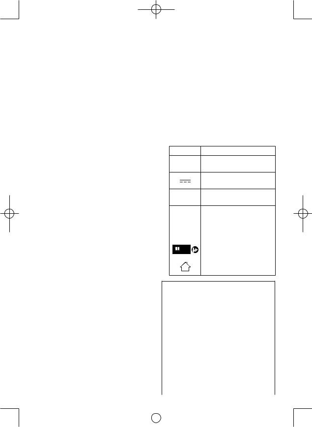
Symbol |
Meaning |
||||||
|
|
V |
Volts |
||||
|
|
|
|
|
|
|
|
|
|
|
|
|
|
|
Direct current |
|
|
|
|
|
|
|
|
|
|
|
|
|
|
|
|
|
|
n0 |
No load speed |
||||
|
|
|
|
|
|
|
|
… min-1 |
Revolutions or reciprocations |
||||||
|
|
|
|
|
|
|
per minutes |
|
|
Ah |
Electrical capacity of battery |
||||
|
|
pack |
|||||
|
|
|
|
|
|
|
|
|
|
|
|
|
|
|
|
|
|
|
|
|
|
|
Read the operating |
|
|
|
|
|
|
|
|
|
|
|
|
|
|
|
instructions before use. |
|
|
|
|
|
|
|
|
|
|
|
|
|
|
|
For indoor use only. |
|
|
|
|
|
|
|
|
 WARNING:
•Do not use other than the Panasonic battery packs that are designed for use with this rechargeable tool.
•Panasonic is not responsible for any damage or accident caused by the use of recycled or counterfeit battery pack.
•Do not dispose of the battery pack in a fire, or expose it to excessive heat.
•Do not drive the likes of nails into the battery pack, subject it to shocks, dismantle it, or attempt to modify it.
•Do not allow metal objects to touch the battery pack terminals.
•Do not carry or store the battery pack in the same container as nails or similar metal objects.
•Do not charge the battery pack in a high-temperature location, such as next to a fire or in direct sunlight. Otherwise, the battery may overheat, catch fire, or explode.
•Never use other than the dedicated charger to charge the battery pack. Otherwise, the battery may leak, overheat, or explode.
- 5 -
|
|
|
|
EY7546_EY7547_EY7550_EY7551_EU.indb 5 |
2011-2-25 14:40:07 |
||
|
|
|
|
•After removing the battery pack from the tool or the charger, always reattach the pack cover. Otherwise, the battery contacts could be shorted, leading to a risk of fire.
•When the Battery Pack Has Deteriorated,
Replace It with a New One. Continued use of a damaged battery pack may result in heat generation, ignition or battery rupture.
II. ASSEMBLY
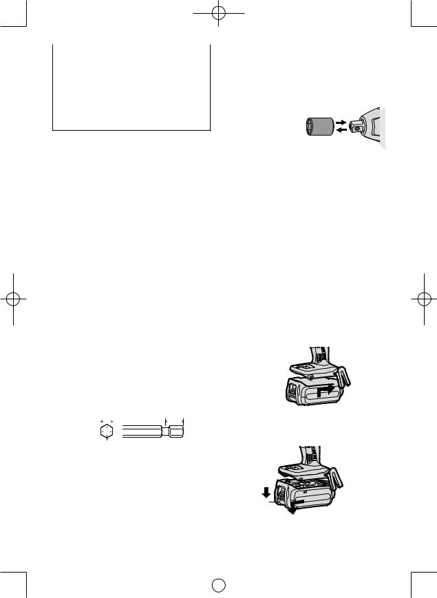
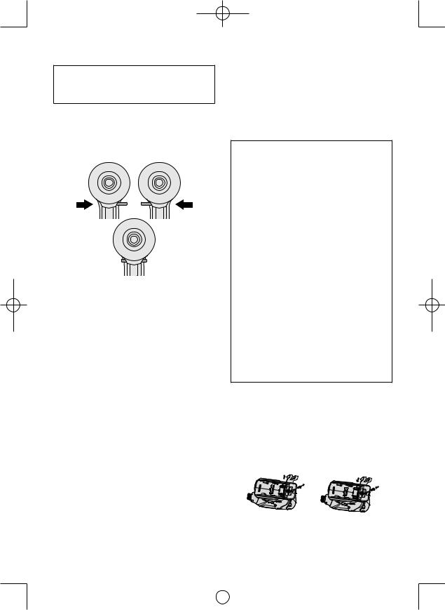
Attaching or Removing Bit
NOTE:
•When attaching or removing a bit, disconnect battery pack from tool or place the switch in the center position (switch lock).
1.Hold the collar of quick connect chuck and pull it out from the driver.
2.Insert the bit into the chuck. Release the collar.
3.The collar will return to its original position when it is released.
4.Pull the bit to make sure it does not come out.
5.To remove the bit, pull out the collar in the same way.
CAUTION:
•If the collar does not return to its original position or the bit comes out when pulled on, the bit has not been properly attached. Make sure the bit is properly attached before use.
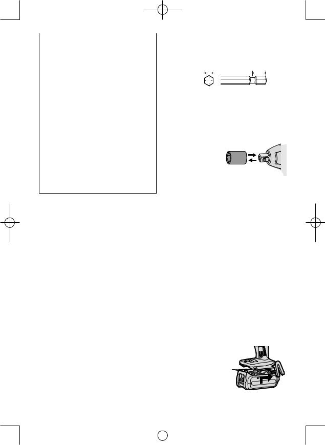
Use 6.35 mm (1/4”) hexagonal bits.
To ensure proper securement of the bit, use only hexagonal bits with 9.5 mm (3/8”) detent.
6.35 mm (1/4") |
9.5 mm (3/8") |
|||||||||
|
|
|
|
|
|
|
|
|
|
|
|
|
|
|
|
|
|
|
|
|
|
|
|
|
|
|
|
|
|
|
|
|
|
|
|
|
|
|
|
|
|
|
|
|
|
|
|
|
|
|
|
|
|
|
|
|
|
|
|
|
|
|
|
|
|
Attaching or Removing Socket
1.Attaching Socket
Attach the socket by sliding the female detent on the bottom of the socket to the square drive on the body.
Make sure the socket is firmly connected to the body.
2.Removing Socket Pull out the socket.
NOTE:
Attaching or Removing Original Options and Sockets
Keep the body above freezing point (0°C 32°F) when attach or detach original options and sockets to the square drive on the body. The cushion rubber in the square drive to push up the ball may get hard under freezing point. This requires extra force in detaching and attaching sockets.
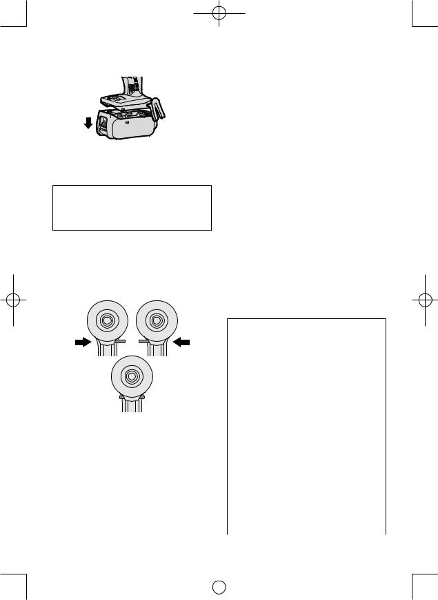
AttachingorRemovingBat tery Pack
1.To connect the battery pack:
Line up the alignment marks and attach the battery pack.
•Slide the battery pack until it locks into position.
Alignment 
 marks
marks 

2.To remove the battery pack:
Pull the button from the front to release the battery pack.
Button
- 6 -
|
|
|
|
EY7546_EY7547_EY7550_EY7551_EU.indb 6 |
2011-2-25 14:40:07 |
||
|
|
|
|
III. OPERATION
3.After use, set the lever to its center position (switch lock).
 WARNING!
•Do not inhale any smoke emitted from the tool or battery pack as it may be harmful.
[Main Body]
Switch and Forward/Reverse
Lever Operation
Forward |
Reverse |
Switch lock
CAUTION:
To prevent damage, do not operate Forward/Reverse lever until the bit comes to a complete stop.
Forward Rotation Switch Operation
1.Push the lever for forward rotation.
2.Depress the trigger switch slightly to start the tool slowly.
3.The speed increases with the amount of depression of the trigger for efficient tightening of screws. The brake operates and the bit stops immediately when the trigger is released.
4.After use, set the lever to its center position (switch lock).
Reverse Rotation Switch
Operation
1.Push the lever for reverse rotation. Check the direction of rotation before use.
2.Depress the trigger switch slightly to start the tool slowly.
CAUTION:
•To eliminate excessive temperature increase of the tool surface, do not operate the tool continuously using two or more battery packs. Tool needs cool off time before switching to another pack.
How to Use the Belt Hook
 WARNING!
•Be sure to attach the belt hook securely to the main unit with the screw firmly fastened. When the belt hook is not firmly attached to the main unit, the hook may disconnect and the main unit may fall.
This may result in an accident or injury.
•Periodically check screw for tightness. If found to be loose, tighten firmly.
•Be sure to attach the belt hook firmly and securely onto a waist belt or other belt. Pay attention that the unit does not slip off the belt. This may result in an accident or injury.
•When the main unit is held by the belt hook, avoid jumping or running with it. Doing so may cause the hook to slip and the main unit may fall.
This may result in an accident or injury.
•When the belt hook is not used, be sure to return it to the storing position. The belt hook may catch on something.
This may result in an accident or injury.
•When the unit is hooked onto the waist belt by the belt hook, do not attach driver bits to the unit. A sharp edge object, such as a drill bit, may cause injury or an accident.
To Change the Belt Hook Location Side
The belt hook can be attached to either side of the unit.
1.Removing the hook
(1)Remove the nut.
(2)Draw out the hook.
2.Attaching the hook to the other side
(1)Insert the hook in the other side.
(2)Tighten the nut fully so that it securely fastened.
- 7 -
|
|
|
|
EY7546_EY7547_EY7550_EY7551_EU.indb 7 |
2011-2-25 14:40:08 |
||
|
|
|
|
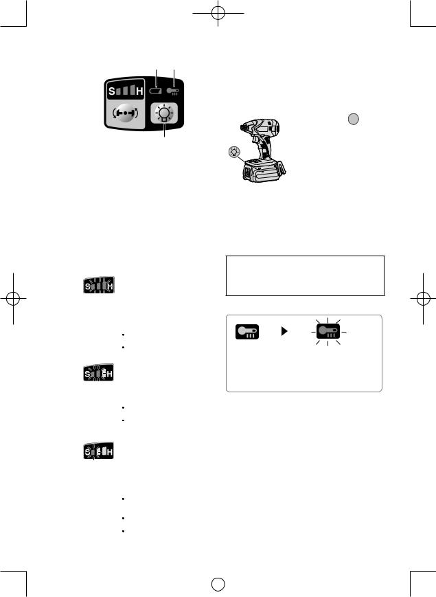
Control Panel
(4) (3)
(1)
(2)
(1) Impact Power Mode Select
 Selecting the impact power among 3 modes (Soft, Medium, Hard).
Press the impact power mode button to set it. The mode changes to hard, medium, or soft each time the button is pressed.
The driver is preset to “hard” impact mode setting when shipped from the manufacturer.
Recommended work guideline table
Impact |
Recommended Application |
|
Power mode |
||
Display |
|
|
H |
Jobs requiring a high level |
|
of torque where there is |
||
no possibility of the bolts |
||
|
or screw breaking, its top |
|
0 – 2300 r.p.m./ |
shearing off, or the bit coming |
|
0 – 2500 r.p.m. |
loose. (This setting provides |
|
maximum torque.) Suitable |
||
and |
||
applications include: |
||
0 – 3000 i.p.m./ |
||
Tightening M8 and larger |
||
0 – 3300 i.p.m./ |
||
bolts |
||
0 – 3500 i.p.m. |
Tightening long screws |
|
|
during interior finishing work |
|
M |
Jobs requiring limited torque |
|
where there is a possibility of |
||
the screw breaking or its top |
||
|
shearing off. (This setting limits |
|
|
torque.) Suitable applications |
|
0 – 1400 r.p.m. |
include: |
|
and |
Tightening bolts with |
|
smaller diameters (M6) |
||
0 – 2800 i.p.m. |
||
Tightening metalwork |
||
|
screws when installing |
|
|
fixtures |
|
S |
Jobs requiring limited torque |
|
where there is a possibility |
||
of the screw breaking, its |
||
|
top shearing off, or the bit |
|
|
coming loose and damaging |
|
|
a finished exterior surface. |
|
0 – 1000 r.p.m. |
(This setting limits torque.) |
|
Suitable applications include: |
||
and |
Tightening bolts smaller |
|
0 – 2000 i.p.m. |
than M6 that may shear |
|
|
easily |
|
|
Tightening screws into |
|
|
molded plastic |
|
|
Installing gypsum wallboard |
Avoid repeatedly depressing the switch when the bolts and screws are securely fastened.
Not doing so may cause a delay in rotation starting, or the Impact Power mode display to flash and prevent rotation from starting for circuit protection.
(2) LED light
Pressing the  button
toggles the LED light on
and off.
The light illuminates with very low current, and it does not adversely affect the performance of the driver during use
or its battery capacity.
CAUTION:
•The built-in LED light is designed to illuminate the small work area temporarily.
•Do not use it as a substitute for a regular flashlight, since it does not have enough brightness.
Caution : DO NOT STARE INTO BEAM.
Use of controls or adjustments or performance of procedures other than those specified herein may result in hazardous radiation exposure.
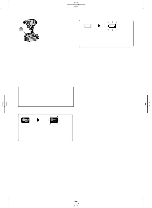
(3) Overheat warning lamp
Off (normal |
Flashing: Overheat |
operation) |
Indicates operation has |
|
been halted due to motor |
|
or battery overheating. |
The overheating protection feature halts driver operation to protect the motor and battery pack in the event of overheating. The overheat warning lamp on the control panel flashes when this feature is active.
•If the overheating protection feature activates, allow the driver to cool thoroughly (at least 30 minutes). The driver is ready for use when the overheat warning lamp goes out.
•Avoid using the driver in a way that causes the overheating protection feature to activate repeatedly.
* i.p.m. = Impact per minute.
- 8 -
|
|
|
|
EY7546_EY7547_EY7550_EY7551_EU.indb 8 |
2011-2-25 14:40:08 |
||
|
|
|
|

(4) Battery low warning lamp
Off (normal |
Flashing (No charge) |
operation) |
Battery protection |
|
feature active |
Excessive (complete) discharging of Liion batteries shortens their service life dramatically. The driver includes a battery protection feature designed to prevent excessive discharging of the battery pack.
•The battery protection feature activates immediately before the battery loses its charge, causing the battery low warning lamp to flash.
•If you notice the battery low warning lamp flashing, charge the battery pack immediately.
Recommended Grip
Use the grip to hold and operate the
driver with one hand. If the job requires
additional force, you can push against
the rear end of the driver with your other
hand.
[Battery Pack]
For Appropriate Use of
Battery Pack
Li-ion Battery Pack
•For optimum battery life, store the Li-ion battery pack following use without charging it.
•When charging the battery pack, confirm that the terminals on the battery charger are free of foreign substances such as dust and water etc. Clean the terminals before charging the battery pack if any foreign substances are found on the terminals.
The life of the battery pack terminals may be affected by foreign substances such as dust and water etc. during operation.
•When battery pack is not in use, keep it away from other metal objects like: paper clips, coins, keys, nails, screws, or other small metal objects that can make a connection from one terminal to another.
Shorting the battery terminals together may cause sparks, burns or a fire.
•When operating the battery pack, make sure the work place is well ventilated.
•When the battery pack is removed from the main body of the tool, replace the battery pack cover immediately in order to prevent dust or dirt from contaminating the battery terminals and causing a short circuit.
Battery Pack Life
The rechargeable batteries have a limited life. If the operation time becomes extremely short after recharging, replace the battery pack with a new one.
[Battery Charger] Charging
CAUTION:
•If the temperature of the battery pack falls approximately below −10°C (14°F), charging will automatically stop to prevent degradation of the battery.
•The ambient temperature range is between 0°C (32°F) and 40°C (104°F).
If the battery pack is used when the bat tery temperature is below 0°C (32°F), the tool may fail to function properly.
•When charging a cool battery pack (below
0°C (32°F)) in a warm place, leave the battery pack at the place and wait for more than one hour to warm up the battery to the level of the ambient temperature.
•Cool down the charger when charging more than two battery packs consecutively.
•Do not insert your fingers into contact hole, when holding charger or any other occasions.
To prevent the risk of fire or damage to the battery charger.
•Do not use power source from an engine generator.
•Do not cover vent holes on the charger and the battery pack.
•Unplug the charger when not in use.
- 9 -
|
|
|
|
EY7546_EY7547_EY7550_EY7551_EU.indb 9 |
2011-2-25 14:40:09 |
||
|
|
|
|
NOTE:
Your battery pack is not fully charged at the time of purchase. Be sure to charge the battery before use.
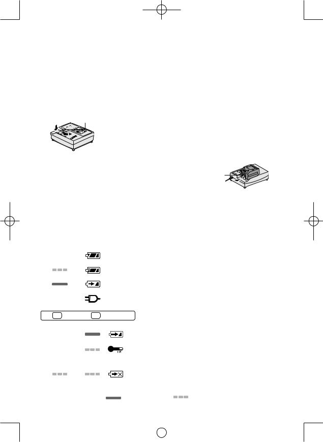
Battery charger
1.Plug the charger into the AC outlet.
2.Insert the battery pack firmly into the charger.
1Line up the alignment marks and place the battery onto the dock on the charger.
2Slide forward in the direction of the arrow.
 Alignment marks
3.During charging, the charging lamp will be lit. When charging is completed, an internal electronic switch will automatically be triggered to prevent overcharging.
•Charging will not start if the battery pack is warm (for example, immediately after heavy-duty operation).
The orange standby lamp will be flashing until the battery cools down. Charging will then begin automatically.
4.The charge lamp (green) will flash slowly once the battery is approximately 80% charged.
5.When charging is completed, the charging lamp in green color will turn off.
6.If the temperature of the batter pack is 0°C or less, charging takes longer to fully charge the battery pack than the standard charging time.
Even when the battery is fully charged, it will have approximately 50% of the power of a fully charged battery at normal operating temperature.
7.Consult an authorized dealer if the charging lamp (green) does not turn off.
8.If a fully charged battery pack is inserted into the charger again, the charging lamp lights up. After several minutes, the charging lamp in green color will turn off.
9.Remove the battery pack while the battery pack release button is held up.
Battery pack release button
LAMP INDICATIONS
|
|
|
|
|
|
|
|
|
|
|
Charging is completed. (Full charge.) |
|
|
|
|
|
|
|
|
|
|
|
|
Battery is approximately 80% charged. |
|
|
|
|
|
|
|
|
|
|
|
|
||
|
|
|
|
|
|
|
|
|
|
|
Now charging. |
|
|
|
|
|
|
|
|
|
|
|
|
|
|
|
|
|
|
|
|
|
|
|
|
|
Charger is plugged into the AC outlet. Ready to charge. |
|
|
|
|
|
|
|
|
|
|
|
|
||
|
|
|
|
|
|
|
(Green) |
(Orange) |
Charging Status Lamp. |
|||
|
|
|
|
|
|
|
||||||
|
|
|
|
|
|
|
Left: green |
Right: orange will be displayed. |
||||
|
|
|
|
|
|
|
|
|
|
|
||
|
|
|
|
|
|
|
|
|
|
|
Battery pack is cool. |
|
|
|
|
|
|
|
|
|
|
|
|
||
|
|
|
|
|
|
|
|
|
|
|
The battery pack is being charged slowly to reduce the load on the battery. |
|
|
|
|
|
|
|
|
|
|
|
|
Battery pack is warm. |
|
|
|
|
|
|
|
|
|
|
|
|
||
|
|
|
|
|
|
|
|
|
|
|
Charging will begin when temperature of battery pack drops. If the temperature of the |
|
|
|
|
|
|
|
|
|
|
|
|
||
|
|
|
|
|
|
|
|
|
|
|
battery pack is -10° or less, the charging status lamp (orange) will also start flashing . |
|
|
|
|
|
|
|
|
|
|
|
|
Charging will begin when the temperature of the battery pack goes up" |
|
|
|
|
|
|
|
|
|
|
|
|
Charging is not possible. Clogged with dust or malfunction of the bat- |
|
|
|
|
|
|
|
|
|
|
|
|
tery pack. |
|
|
|
|
|
|
|
|
|
|
|
|
|
|
|
|
|
|
|
|
|
Turn off |
|
Lit |
Flashing |
||
- 10 -
|
|
|
|
EY7546_EY7547_EY7550_EY7551_EU.indb 10 |
2011-2-25 14:40:10 |
||
|
|
|
|
Information for Users on Collection and Disposal of Old Equip ment and used Batteries
These symbols on the products, packaging, and/or accompanying documents mean
that used electrical and electronic products and batteries should not be mixed with general household waste.
For proper treatment, recovery and recycling of old products and used batteries, please take them to applicable collection points, in accordance with your national legislation
and the Directives 2002/96/EC and 2006/66/EC.
By disposing of these products and batteries correctly, you will help to save valuable resources and prevent any potential negative effects on human health and the
environment which could otherwise arise from inappropriate waste handling.
For more information about collection and recycling of old products and batteries, please contact your local municipality, your waste disposal service or the point of sale where you purchased the items.
Penalties may be applicable for incorrect disposal of this waste, in accordance with national legislation.
For business users in the European Union
If you wish to discard electrical and electronic equipment, please contact your dealer or supplier for further information.
[Information on Disposal in other Countries outside the European Union]
These symbols are only valid in the European Union. If you wish to discard these items, please contact your local authorities or dealer and ask for the correct method of disposal.
Note for the battery symbol (bottom two symbol examples):
This symbol might be used in combination with a chemical symbol. In this case it complies with the requirement set by the Directive for the chemical involved.
IV. MAINTENANCE |
|
After tightening, always check the torque |
|||||
|
|
variety of factors including the followings. |
|||||
• Use only a dry, soft cloth for wiping the unit. |
|
with a torque wrench. |
|||||
|
|
|
|
|
|
|
|
Do not use a damp cloth, thinner, benzine, |
1) Voltage |
|
|
|
|||
or other volatile solvents for cleaning. |
|
When the battery pack becomes near- |
|||||
• In the event that the inside of the tool or |
|
||||||
|
ly discharged, the voltage decreases and |
||||||
battery pack is exposed to water, drain |
|
the tightening torque drops. |
|||||
and allow to dry as soon as possible. |
|
|
|
|
|
|
|
Carefully remove any dust or iron filings |
|
|
Bolt Tightening Conditions |
|
|
||
that collect inside the tool. If you experi- |
|
|
|
|
|
|
|
ence any problems operating the tool, |
EY7546 |
|
|
|
|||
consult with a repair shop. |
|
|
|
M10 x 35 mm M12, M14, M16 x 45 mm |
|||
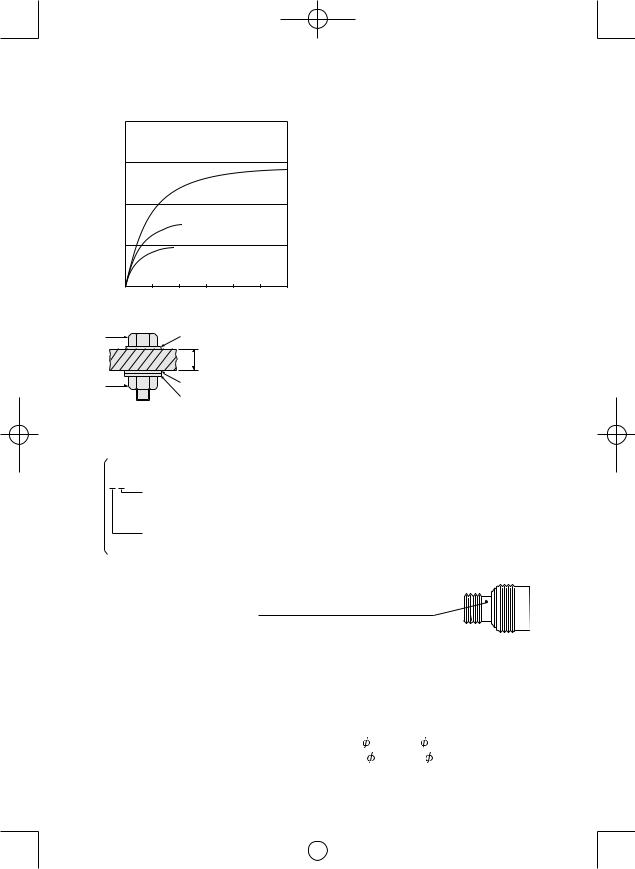
V. TIGHTENING |
|
|
N σ m |
Standard bolt |
|||
|
196.0 |
|
|
|
|
||
|
|
(kgf-cm) |
|
|
|
||
TORQUE |
|
|
|
|
|
|
|
|
2000 |
|
M16 |
|
|||
|
|
|
|
||||
|
|
|
|
|
|
||
The power required for tightening a bolt will |
torque |
147.0 |
|
|
|
|
|
|
M14 |
|
|||||
vary, according to bolt material and size, as |
1500 |
|
|
||||
|
|
|
|
|
|
||
well as the material being bolted. Choose |
Tightening |
|
|
|
|
|
|
the length of tightening time accordingly. |
98.0 |
|
|
|
|
||
Reference values are provided below. |
|
1000 |
|
M12 |
|
||
(They may vary according to tightening conditions.) |
|
|
|
|
|
||
|
|
|
|
|
|
|
|
Factors Affecting Tighten |
|
49.0 |
|
|
|
|
|
|
|
500 |
|
M10 |
|
||
ing Torque |
|
|
|
|
|
|
|
The tightening torque is affected by a wide |
|
|
|
|
|
||
|
0.0 |
0.5 1.0 1.5 2.0 2.5 3.0 |
|||||
- 11 - |
|
|
|
Tightening time (Sec.) |
|||
|
|
|
|
EY7546_EY7547_EY7550_EY7551_EU.indb 11 |
2011-2-25 14:40:10 |
||
|
|
|
|

EY7546
M8, M10 x 35 mm. M12 x 45 mm
N σ m High tensile bolt
(kgf-cm)
196.02000
torque |
147.0 |
|
|
|
|
|
|
|
|
|
|
|
|
|
|
|
|
||
1500 |
|
|
|
|
|
|
|
||
Tightening |
|
|
|
|
|
M10 |
|
M12 |
|
98.0 |
|
|
|
|
|
|
|
||
|
1000 |
|
|
|
|
|
|
|
|
|
49.0 |
|
|
|
|
|
|
|
|
|
|
|
|
|
|
|
|
|
|
|
500 |
|
M8 |
|
|
|
|
|
|
|
|
|
|
|
|
|
|
|
|
|
|
|
|
|
|
|
|
|
|
|
0.0 |
0.5 |
1.0 |
1.5 |
2.0 |
2.5 |
3.0 |
||
|
|
|
Tightening time (Sec.) |
|
|
||||
EY7547 M10 x 35 mm M12, M14, M16 x 45 mm
|
N σ m |
|
|
|
|
Standard bolt |
|||
|
(kgf-cm) |
|
|
|
|
|
|
|
|
|
196.0 |
|
|
|
|
|
|
|
|
|
2000 |
|
|
|
|
|
|
|
|
|
|
|
|
|
|
|
|
M16 |
|
|
147.0 |
|
|
|
|
|
|
|
|
|
|
|
|
|
|
|
|
|
|
|
1500 |
|
|
|
|
|
|
|
|
torque |
98.0 |
|
|
|
|
|
|
|
|
|
|
|
|
|
|
|
|
||
Tightening |
1000 |
|
|
M14 |
|
|
|
|
|
|
|
|
|
|
|
|
|
||
|
49.0 |
|
|
|
|
|
|
|
|
|
500 |
|
M12 |
|
|
|
|
|
|
|
|
|
M10 |
|
|
|
|
|
|
|
|
|
|
|
|
|
|
|
|
|
0.0 |
0.5 |
1.0 |
1.5 |
2.0 |
2.5 |
3.0 |
||
Tightening time (Sec.)
EY7547
M8, M10 x 35 mm. M12 x 45 mm
N σ m High tensile bolt
(kgf-cm)
196.02000
torque |
147.0 |
|
|
|
|
|
|
|
|
|
|
|
|
|
|
|
|
|
|
|
1500 |
|
|
|
|
|
M12 |
||
Tightening |
|
|
|
|
|
|
|
||
98.0 |
|
|
M10 |
|
|
|
|
|
|
|
1000 |
|
|
|
|
|
|
|
|
|
49.0 |
|
|
|
|
|
|
|
|
|
500 |
M8 |
|
|
|
|
|
||
|
|
|
|
|
|
|
|
||
|
|
|
|
|
|
|
|
|
|
|
0.0 |
0.5 |
1.0 |
1.5 |
2.0 |
2.5 |
3.0 |
||
EY7550
M10 x 35 mm M12, M14, M16 x 45 mm
N σ m Standard bolt
(kgf-cm)
|
196.0 |
|
|
|
|
|
|
|
|
|
2000 |
|
|
|
|
|
|
M16 |
|
torque |
|
|
|
|
|
|
|
|
|
147.0 |
|
|
|
|
|
|
M14 |
|
|
|
|
|
|
|
|
|
|
|
|
Tightening |
1500 |
|
|
|
|
|
|
|
|
98.0 |
|
|
|
|
|
|
|
|
|
|
1000 |
|
|
|
M12 |
|
|
|
|
|
|
|
|
|
|
|
|
|
|
|
49.0 |
|
|
|
|
|
|
|
|
|
500 |
|
|
M10 |
|
|
|
|
|
|
|
|
|
|
|
|
|
|
|
|
|
|
|
|
|
|
|
|
|
|
0.0 |
0.5 |
1.0 |
1.5 |
2.0 |
2.5 |
3.0 |
||
Tightening time (Sec.)
EY7550
M8, M10 x 35 mm. M12 x 45 mm
N σ m High tensile bolt
(kgf-cm)
196.02000
torque |
147.0 |
|
|
|
|
|
|
|
|
|
|
|
|
|
|
|
|
||
1500 |
|
|
|
|
|
|
|
||
Tightening |
|
|
|
|
|
M10 |
|
M12 |
|
98.0 |
|
|
|
|
|
|
|
||
|
1000 |
|
|
|
|
|
|
|
|
|
49.0 |
|
|
|
|
|
|
|
|
|
500 |
|
M8 |
|
|
|
|
|
|
|
|
|
|
|
|
|
|
|
|
|
|
|
|
|
|
|
|
|
|
|
0.0 |
0.5 |
1.0 |
1.5 |
2.0 |
2.5 |
3.0 |
||
Tightening time (Sec.)
EY7551
M10 x 35 mm M12, M14, M16 x 45 mm
N σ m Standard bolt
(kgf-cm)
196.02000
|
|
|
|
|
|
|
|
M16 |
|
|
147.0 |
|
|
|
|
|
|
|
|
|
|
|
|
|
|
|
|
|
|
|
1500 |
|
|
|
|
|
|
|
|
torque |
98.0 |
|
|
|
|
|
|
|
|
|
|
|
|
|
|
|
|
||
Tightening |
1000 |
|
M14 |
|
|
|
|
|
|
|
|
|
|
|
|
|
|
||
|
|
|
|
|
|
|
|
|
|
|
49.0 |
|
|
|
|
|
|
|
|
|
500 |
M12 |
|
|
|
|
|
|
|
|
|
|
M10 |
|
|
|
|
|
|
|
|
|
|
|
|
|
|
|
|
|
0.0 |
0.5 |
1.0 |
1.5 |
2.0 |
2.5 |
3.0 |
||
Tightening time (Sec.) |
- 12 - |
Tightening time (Sec.) |
|
|
|
|
|
|
EY7546_EY7547_EY7550_EY7551_EU.indb 12 |
2011-2-25 14:40:11 |
||
|
|
|
|
EY7551
M8, M10 x 35 mm. M12 x 45 mm
N σ m High tensile bolt
(kgf-cm)
196.02000
torque |
147.0 |
|
|
|
|
|
|
|
1500 |
|
|
|
|
|
M12 |
Tightening |
|
|
|
|
|
|
|
98.0 |
|
M10 |
|
|
|
|
|
|
1000 |
|
|
|
|
|
|
|
49.0 |
|
|
|
|
|
|
|
500 |
M8 |
|
|
|
|
|
|
|
|
|
|
|
||
|
0.0 |
0.5 |
1.0 |
1.5 |
2.0 |
2.5 |
3.0 |
|
|
Tightening time (Sec.) |
|
||||
Bolt |
|
Washer |
|
|
|
||
|
|
|
|
|
|
||
|
|
|
|
Steel plate |
|
|
|
|
|
|
|
thickness 10 mm (3/8") |
|||
|
Nut |
|
Washer |
|
|
|
|
Spring washer
Tightening conditions
•The following bolts are used.
Standard bolts: Strength type 4.8 High tensile type 12.9
Explanation of the strength type
4.8
 Bolt yield point
(80% of tensile strength) 32 kgf/mm2 (45000 psi)
 Bolt tensile strength 40 kgf/mm2 (56000 psi)
2)Tightening time
Longer tightening time results in increased tightening torque. Excessive tightening, however, adds no value and reduces the life of the tool.
3)Different bolt diameters
The size of the bolt diameter affects the tightening torque.
Generally, as the bolt diameter increases, tightening torque rises.
4)Tightening conditions
 Tightening torque will vary, even with the same bolt, according to grade, length, and torque coefficient (the fixed coefficient indi cated by the manufacturer upon produc tion).
 Tightening torque will vary, even with the same bolting material (e.g. steel), according to the surface finish.
 Torque is greatly reduced when the bolt and nut start turning together.
5)Socket play
Torque is lowered as the six-sided configu ration of the socket of the wrong size is used to tighten a bolt.
6)Switch (Variable speed control trigger)
Torque is lowered if the unit is used with the switch not fully depressed.
7)Effect of Connecting Adaptor
The tightening torque will be lowered through the use of a universal joint or a connecting adaptor.
VI. ACCESSORIES
Use only suitable size of bit.
Panasonic original Optional Quick change chuck (EY9HX110E).
Chuck Size: 6.35 mm (1/4”) hex
VII.APPENDIX
MAXIMUM RECOMMENDED CAPACITIES
Model |
|
EY7546 |
EY7547 |
|
EY7550 |
EY7551 |
Screw driving |
Wood screw |
|
3.5 mm - |
9.5 mm |
|
|
Self-drilling screw |
|
3.5 mm - |
6 mm |
|
||
Bolt fastening |
|
|
Standard bolt:M6-M16 |
|
||
|
|
High tensile bolt : M6 - M12 |
|
|||
|
|
|
|
|||
- 13 -
|
|
|
|
EY7546_EY7547_EY7550_EY7551_EU.indb 13 |
2011-2-25 14:40:11 |
||
|
|
|
|

VIII. SPECIFICATIONS
MAIN UNIT
Model |
|
EY7546 |
EY7547 |
EY7550 |
EY7551 |
|
Motor voltage |
|
14.4 V |
|
18 V |
||
|
soft mode |
|
0 - 1000 |
min-1 |
(rpm) |
|
No load speed |
medium mode |
|
0 - 1400 min-1 |
(rpm) |
|
|
|
hard mode |
0 - 2500 min-1 (rpm) |
0 - 2300 min-1 (rpm) |
0 - 2500 min-1 (rpm) |
0 - 2300 min-1 (rpm) |
|
Maximum torque |
|
150 N·m (1330 in.Ibs) |
200 N·m (1770 in.Ibs) |
155 N·m (1370 in.Ibs) |
205 N·m (1815 in.Ibs) |
|
|
soft mode |
|
0 - 2000 |
min-1 |
(rpm) |
|
Impact per minute |
medium mode |
|
0 - 2800 min-1 |
(rpm) |
|
|
|
hard mode |
0 - 3000 min-1 (rpm) |
0 - 3500 min-1 (rpm) |
0 - 3300 min-1 (rpm) |
0 - 3500 min-1 (rpm) |
|
Overall length |
|
143 mm (5-5/8˝) |
155 mm (6-1/8˝) |
143 mm (5-5/8˝) |
155 mm (6-1/8˝) |
|
Weight (with battery pack EY9L44) |
1.5 kg (3.3Ibs) |
1.55 kg (3.4Ibs) |
|
— |
— |
|
Weight (with battery pack EY9L50) |
— |
— |
1.6 kg (3.5Ibs) |
1.65 kg (3.6Ibs) |
||
BATTERY PACK
Model |
EY9L41 |
EY9L42 |
EY9L44 |
EY9L50 |
|
Storage battery |
|
|
Li-ion |
|
|
Battery voltage |
14.4 V DC |
14.4 V DC |
18 V DC |
||
(3.6 V x 4 cells) |
(3.6 V x 8 cells) |
(3.6 V x 10 cells) |
|||
|
|||||
BATTERY CHARGER
Model |
|
EY0L81 |
|
|
|
Electrical rating |
See the rating plate on the bottom of the charger. |
|
|||
|
EY9L41 |
EY9L42 |
EY9L44 |
|
EY9L50 |
Charging time |
Usable: 45 min. |
Usable: 30 min. |
Usable: 50 min. |
||
|
Full: 60 min. |
Full: 35 min. |
Full: 65 min. |
||
NOTE: This chart may include models that are not available in your area. Please refer to the latest general catalogue.
For the dealer name and address, please see the included warranty card.
- 14 -
|
|
|
|
EY7546_EY7547_EY7550_EY7551_EU.indb 14 |
2011-2-25 14:40:12 |
||
|
|
|
|
ONLY FOR U. K.
IX. ELECTRICALPLUG
INFORMATION
FOR YOUR SAFETY PLEASE READ THE FOLLOWING TEXT CAREFULLY
This appliance is supplied with a moulded three pin mains plug for your safety and convenience.
A 5 amp fuse is fitted in this plug.
Should the fuse need to be replaced please ensure that the replacement fuse has a rating of 5 amp and that it is approved by ASTA or BSI to BS1362.
Check for the ASTA mark  or the BSI mark
  on the body of the fuse.
If the plug contains a removable fuse cover you must ensure that it is refitted when the fuse is replaced.
If you lose the fuse cover the plug must not be used until a replacement cover is obtained.
A replacement fuse cover can be purchased from your local Panasonic Dealer.
IF THE FITTED MOULDED PLUG IS UNSUITABLE FOR THE SOCKET OUTLET IN YOUR HOME THEN THE FUSE SHOULD BE REMOVED AND THE PLUG CUT OFF AND DISPOSED OF SAFELY.
THERE IS A DANGER OF SEVERE ELECTRICAL SHOCK IF THE CUT OFF PLUG IS INSERTED INTO ANY 13 AMP SOCKET.
If a new plug is to be fitted please observe the wiring code as shown below.
If in any doubt please consult a qualified electrician.
IMPORTANT:
The wires in this mains lead are coloured in accordance with the following code:
Blue: Neutral
Brown: Live
As the colours of the wire in the mains lead of this appliance may not correspond with the coloured markings identifying the terminals in your plug, proceed as follows.
The wire which is coloured BLUE must be connected to the terminal in the plug which is marked with the letter N or coloured BLACK.
The wire which is coloured BROWN must be connected to the terminal in the plug which is marked with the letter L or coloured RED.
Under no circumstances should either of these wires be connected to the earth terminal of the three pin plug, marked with the letter E or the Earth Symbol .
.
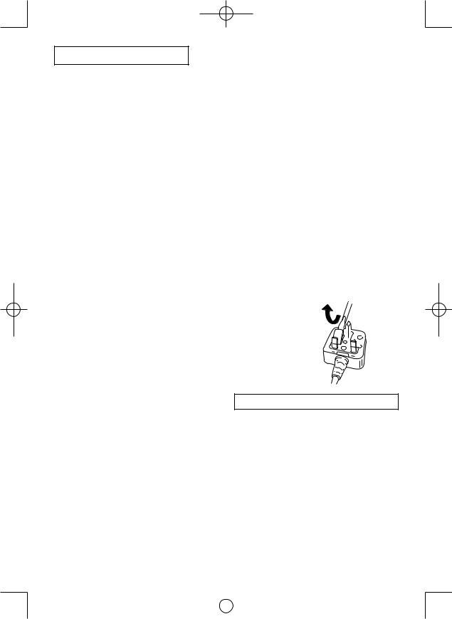
How to replace the fuse: Open the fuse compartment with a screwdriver and replace the fuse and fuse cover if it is removable.
Fuse Cover 


This apparatus was produced to BS800.
- 15 -
|
|
|
|
EY7546_EY7547_EY7550_EY7551_EU.indb 15 |
2011-2-25 14:40:12 |
||
|
|
|
|
Original-Anleitung: Englisch Übersetzung der Original-Anleitung: Andere Sprachen
Dieses Werkzeug, als komplette Einheit mit einem Akku, erfüllt die entsprechenden IPSchutzgrade auf der Basis der IEC-Vorschriften.
Definition des IP-Codes
IP5X: Staubeintritt wird nicht vollständig verhütet, aber Staub darf nicht in einer Menge eindringen, die den zufrieden stellenden Betrieb des Werkzeugs beeinträchtigt oder die Sicherheit gefährdet (Für den Fall, dass Talkumpuder unter 75 μm in das Werkzeug eindringt).
IPX6: Wasser, das durch kräftige Düsen aus allen Richtungen gegen das Werkzeug gespritzt wird, darf keine schädlichen Auswirkungen haben (Für den Fall, dass eine Wassermenge von ca. 100 L/min mit normaler Temperatur aus 3 m Entfernung 3 Minuten lang durch eine Düse von 12,5 mm Innendurchmesser in das Werkzeug injiziert wird).
EINGESCHRÄNKTE GARANTIE
Die Schutzart IP56 qualifiziert diese Maschine für minimale Auswirkung von Wasser oder Staub, aber nicht für die Zusicherung der Leistung unter solchen Bedingungen. Weitere Einzelheiten zur Funktionstüchtigkeit finden Sie in den Sicherheitsund Gebrauchsanweisungen.
Lesen Sie bitte vor der ersten Inbetriebnahme dieses Gerätes das separate Handbuch „Sicherheitsmaßregeln“ sorgfältig durch.
I. WEITERE WICHTIGE SICHERHEITSREGELN
1)Geeigneten Gehörschutz tragen, wenn das Werkzeug längere Zeit im Betrieb ist!
2)Denken Sie daran, dass das Werkzeug ständig betriebsbereit ist, da es nicht an die Steckdose angeschlossen werden muss.
3)Beim Schrauben in Wände, Fußböden usw. können stromführende Kabel berührt werden. DAHER NIE DAS VIER KANTSCHNELLSPANNFUTTER ODER ANDERE VORDERE METALLTEILE BERÜHREN! Das Werkzeug beim Schrauben nur am Kunststoffgriff halten, um in solchen Fällen vor elektrischen Schlägen geschützt zu sein.
4)Betätigen Sie den Rechts-/Linkslauf- Umschalthebel NICHT, wenn der Haupts chalter eingeschaltet ist. Der Akku entlädt sich sonst schnell, und das Gerät kann beschädigt werden.
5)Beim Aufladen kann sich das Ladegerät etwas erhitzen. Dies ist normal.
Den Akku daher NICHT über lange Zeit aufladen.
6)Stellen Sie den Rechts-/Linkslauf- Umschalthebel zum Lagern oder Tragen des Werkzeugs auf die Mittenstellung (Schaltersperre).
7)Belasten Sie das Werkzeug nicht, indem Sie den Elektronikschalter halb gedrückt halten (Drehzahlregelmodus), sodass der Motor stehen bleibt.
Symbol Bedeutung
V |
Volt |
Gleichstrom
n0 Leerlaufdrehzahl
… min-1 |
Drehzahl oder Hubzahl pro |
|
|
|
Minute |
|
Ah |
Akkukapazitat in Ampere |
|
Stunden |
|
|
|
|
|
|
|
|
|
Lesen Sie die |
|
|
Bedienungsanleitung vor |
|
|
Gebrauch. |
|
|
Nur für Inneneinsatz. |
 WARNUNG:
•Verwenden Sie nur die Panasonic-Akkus, die für den Einsatz mit dieser Akku-Maschine ausgelegt sind.
•Panasonic übernimmt keine Verantwortung für etwaige Schäden oder Unfälle, die durch den Gebrauch von recycelten oder gefälschten Akkus verursacht werden.
•Werfen Sie den Akku nicht ins Feuer, und setzen Sie ihn auch keiner übermäßigen Wärme aus.
•Unterlassen Sie das Einschlagen von Nägeln in den Akku sowie Erschüttern, Zerlegen oder Abändern des Akkus.
•Achten Sie darauf, dass keine Metallgegenstände mit den Kontakten des Akkus in Berührung kommen.
- 16 -
|
|
|
|
EY7546_EY7547_EY7550_EY7551_EU.indb 16 |
2011-2-25 14:40:13 |
||
|
|
|
|
•Unterlassen Sie das Tragen oder Aufbewahren des Akkus zusammen mit Nägeln oder ähnlichen Metallgegenständen im selben Behälter.
•Laden Sie den Akku nicht an einem heißen Ort, wie z. B. in der Nähe eines Feuers oder in direktem Sonnenlicht. Anderenfalls kann der Akku überhitzen, Feuer fangen oder explodieren.
•Verwenden Sie nur das zugehörige Lade gerät zum Laden des Akkus. Anderenfalls kann der Akku auslaufen, überhitzen oder explodieren.
•Nachdem Sie den Akku von der Maschine oder dem Ladegerät abgenommen haben, bringen Sie stets die Akkuabdeckung wieder an. Anderenfalls könnten die Akkukontakte kurzgeschlossen werden, was zu einem Brand führen kann.
•Wenn der Akku schwach geworden ist, ersetzen Sie ihn durch einen neuen. Fortgesetzter Gebrauch eines beschädigten Akkus kann zu Wärmeerzeugung, Entzündung oder Bruch führen.
II. BAUGRUPPE
AnbringenoderAbnehmen des Bits
HINWEIS:
•TrennenSievordemAnbringenoderAbneh men eines Bits den Akku vom Werkzeug ab, oder stellen Sie den Elektronikschalter auf die Mittelstellung (Schaltersperre).
1.Die Hülse des Schnellspannfutters halten und vom Schrauber herausziehen.
2.Den Bit in das Bohrfutter einsetzen. Die Hülse loslassen.
3.Der Ring springt in seine Ausgangsposition zurück, wenn er losgelassen wird.
4.An dem Bit ziehen, um sicherzustellen, das er nicht abgezogen werden kann.
5.Zum Entfernen des Bits die Hülse auf die gleiche Weise herausziehen.
VORSICHT:
•Wenn der Ring nicht in seine Ausgangs position zurückkehrt oder wenn sich der Bit löst, wenn an ihm gezogen wird, wurde der Bit nicht ordnungsgemäß eingesetzt. Vor der Inbetriebnahme sicher stellen, dass der Bit ordnungsgemäß befestigt ist.
Verwenden Sie 6,35-mm-(1/4”)-Sechskant bits.
Um einwandfreie Sicherung des Bits zu gewährleisten, verwenden Sie nur Sechs kantbits mit 9,5 mm (3/8”) Arretierung.
6.35 mm (1/4") |
9.5 mm (3/8") |
|||||||||
|
|
|
|
|
|
|
|
|
|
|
|
|
|
|
|
|
|
|
|
|
|
|
|
|
|
|
|
|
|
|
|
|
|
|
|
|
|
|
|
|
|
|
|
|
|
|
|
|
|
|
|
|
|
|
|
|
|
|
|
|
|
|
|
|
|
Anbringen oder Abnehmen einer Stecknuss
1.Anbringen einer Stecknuss
Bringen Sie die Stecknuss an, indem Sie die Fassung an der Unterseite der Stecknuss auf den Vierkant am Werkzeug schieben.
Vergewissern Sie sich, dass die Stecknuss fest mit dem Werkzeug ver bunden ist.
2.Abnehmen einer Stecknuss Ziehen Sie die Stecknuss ab.
HINWEIS:
Anbringen oder Abnehmen von Originalzubehör und Stecknüssen Halten Sie das Werkzeug über dem Gefrierpunkt (0°C), wenn Sie Originalzubehör und Stecknüsse am Vierkant des Werkzeugs anbringen oder davon abnehmen. Das Gummikissen im Vierkant, das die Kugel hochdrückt, kann unterhalb des Gefrierpunkts hart werden. Dies erfordert zusätzliche Kraft beim Abnehmen und Anbringen von Stecknüssen.
Anbringen oder Abnehmen des Akkus
1.Zum Anschließen des Akkus:
Die Ausrichtmarkierungen aufeinander ausrichten, und den Akku anbringen.
• Den Akku einschieben, bis er einrastet.
Ausrichtmarkierungen
- 17 -
|
|
|
|
EY7546_EY7547_EY7550_EY7551_EU.indb 17 |
2011-2-25 14:40:13 |
||
|
|
|
|
2.Zum Entfernen des Akkus:
Zum Abnehmen des Akkus am Knopf an der Vorderseite ziehen.
Knopf

III. BETRIEB
 WARNUNG!
•Atmen Sie nicht den vom Werkzeug oder vom Akkupack ausströmenden Rauch ein, da er gesundheitsschädlich sein kann.
[Hauptteil]
Umschalten und Betätigung des Rechts-/Linkslauf- Umschalthebels
Rechts |
Links |
Schaltersperre
VORSICHT:
N i c h t d e n R e c h t s - / L i n k s l a u f - Umschalthebel betätigen, bevor der Bit vollständig zur Ruhe gekommen ist, um Schäden zu verhindern.
Rechtslauf-Schalterbetäti- gung
1.Für Rechtslauf den Hebel drücken.
2.Drücken Sie den Schalter leicht, um das Werkzeug langsam zu starten.
3.Die Drehzahl nimmt zu, je stärker der Auslöser gedrückt wird, um effizientes Anziehen von Schrauben zu ermöglichen. Beim Loslassen des Auslösers wird die Bremse betätigt und der Bit sofort angehalten.
4.Nach der Verwendung den Hebel auf die Mittelposition zurückstellen (Schalter sperre).
Linkslauf - Schalterbetäti gung
1.Für Linkslauf den Hebel drücken. Die Drehrichtung vor dem Betrieb prüfen.
2.Drücken Sie den Schalter leicht, um das Werkzeug langsam zu starten.
3.Nach der Verwendung den Hebel auf die Mittelposition zurückstellen (Schalter sperre).
VORSICHT:
•Um übermäßigen Temperaturanstieg der
Werkzeugoberfläche zu vermeiden, sollte das Werkzeug nicht kontinuierlich mit zwei oder mehr Akkus betrieben werden. Das Werkzeug muss vor dem Anschluss eines anderen Akkus abkühlen.
Verwenden des Riemen hakens
 WARNUNG!
•Unbedingt den Riemenhaken am Haupt gerät sicher befestigen, indem die Schraube fest angezogen wird. Wenn der Riemenhaken am Hauptgerät nicht gut befestigt ist, kann sich der Haken lösen und das Hauptgerät herunterfallen.
Dies kann einen Unfall oder Verletzungen zur Folge haben.
•Überprüfen Sie die Festigkeit der Schraube regelmäßig. Ist sie locker, muss sie fest angezogen werden.
•Den Riemenhaken unbedingt sicher und gut am Gürtelriemen oder einem anderen Riemen befestigen. Darauf achten, dass das Gerät nicht vom Riemen abrutscht. Dies kann einen Unfall oder Verletzungen zur Folge haben.
•Wenn das Hauptgerät vom Riemenhaken gehalten wird, nicht damit springen oder laufen. Anderenfalls kann der Haken abrutschen und herunterfallen.
Dies kann einen Unfall oder Verletzungen zur Folge haben.
- 18 -
|
|
|
|
EY7546_EY7547_EY7550_EY7551_EU.indb 18 |
2011-2-25 14:40:13 |
||
|
|
|
|

•Wenn der Riemenhaken nicht verwendet wird, unbedingt in seine Lagerposition bringen. Der Riemenhaken könnte sich irgendwo verfangen.
Dies kann einen Unfall oder Verletzungen zur Folge haben.
•Wenn Sie das Werkzeug mit dem Gürtel haken an den Hüftgürtel hängen, bringen Sie außer Schrauberbits keine anderen Bits am Werkzeug an.
Ändern der Befestigungs seite des Riemenhakens
Der Riemenhaken kann auf beiden Seiten des Gerätes befestigt werden.
1.Entfernen des Hakens
(1)Entfernen Sie die Schraube.
(2)Ziehen Sie den Haken heraus.
2.Befestigen des Hakens auf der anderen Seite
(1)Führen Sie den Haken auf der anderen Seite ein.
(2)Ziehen Sie die Schraube gut fest.
Bedienfeld
(4) (3)
(1)
(2)
(1) Wahl des Schlagkraftmodus
 Wählen Sie einen von 3 Schlagkraftmodi (Schwach, Mittel, Stark).
Drücken Sie die SchlagkraftmodusWahltaste. Der Modus wechselt mit jedem Drücken der Taste auf „Stark“, „Mittel“ oder „Schwach“.
Der Schrauber wurde werksseitig vom Hersteller auf den Schlagkraftmodus „Stark“ eingestellt.
Tabelle für empfohlene Arbeitsricht linien
Schlagkraftmodus |
Empfohlene Anwendung |
|
anzeige |
||
|
||
H |
Arbeiten, die ein starkes |
|
Drehmoment erfordern, wenn |
||
keine Gefahr besteht, dass |
||
|
die Schraube bricht, ihr Kopf |
|
0 – 2300 U/min/ |
abschert, oder das Bit sich |
|
löst. (Diese Einstellung liefert |
||
0 – 2500 U/min |
||
das maximale Drehmoment.) |
||
und |
Geeignete Anwendungen: |
|
0 – 3000 S/min/ |
Anziehen von M8und |
|
0 – 3300 S/min/ |
größeren Schrauben |
|
0 – 3500 S/min |
Anziehen von langen |
|
Schrauben bei |
||
|
||
|
Innenverschalungsarbeiten |
|
M |
Arbeiten, die ein begrenztes |
|
Drehmoment erfordern, wenn |
||
die Gefahr besteht, dass die |
||
|
Schraube bricht oder ihr Kopf |
|
|
abschert. (Diese Einstellung |
|
0 – 1400 U/min |
begrenzt das Drehmoment.) |
|
Geeignete Anwendungen: |
||
und |
||
Anziehen von Schrauben |
||
0 – 2800 S/min |
mit kleinerem Durchmesser |
|
|
(M6) |
|
|
Anziehen von Metallschrau |
|
|
ben beim Installieren von |
|
|
Beschlägen |
|
S |
Arbeiten, die ein begrenztes |
|
Drehmoment erfordern, |
||
wenn die Gefahr besteht, |
||
|
dass die Schraube bricht, |
|
|
ihr Kopf abschert, oder der |
|
|
Bit sich löst und eine fertige |
|
|
Außenfläche beschädigt. |
|
0 – 1000 U/min |
(Diese Einstellung begrenzt |
|
das Drehmoment.) |
||
und |
||
Geeignete Anwendungen: |
||
0 – 2000 S/min |
Anziehen von Schrauben, |
|
|
die kleiner als M6 sind und |
|
|
leicht abscheren |
|
|
Anziehen von Schrauben in |
|
|
Formpressmaterial |
|
|
Installieren von Gipsbau |
|
|
platten |
* S/min = Schläge pro Minute
Vermeiden Sie das wiederholte Niederdrücken des Schalters, wenn die Bolzen und Schrauben richtig festgezogen sind.
Anderenfalls kann der Start der Drehbewegung verzögert wurden oder die Schlagkraftmodusanzeige blinken, so dass der Start der Drehbewegung verhindert wird, um die Schaltkreise zu schützen.
- 19 -
|
|
|
|
EY7546_EY7547_EY7550_EY7551_EU.indb 19 |
2011-2-25 14:40:14 |
||
|
|
|
|
(2) LED-Leuchte
Betätigen Sie vor der
Benutzung der LED-
Leuchte einmal den Ein-
Aus-Schalter.
Drücken Sie die LED-
Leuchten-Einschalttaste
 .
.
Die Leuchte benötigt nur sehr wenig Strom und beeinträchtigt nicht die Leistung der Maschine oder die Akkukapazität während der Benutzung.
VORSICHT:
•Die eingebaute LED dient zur vorübergehenden Beleuchtung des kleinen Arbeitsbereichs.
•Benutzen Sie sie nicht als Ersatz für eine reguläre Taschenlampe, weil sie nicht hell genug ist.
•Die LED-Leuchte schaltet sich aus, wenn die Maschine 5 Minuten lang nicht benutzt wird.
Vorsicht: SEHEN SIE NICHT IN DEN STRAHL.
Die Benutzung von Bedienelementen oder Einstellungen, oder die Durchführung von Vorgängen, die hier nicht beschrieben sind, kann zu gefährlicher Strahlungsfreisetzung führen.
(3) Überhitzungs-Warnlampe
(4) Akkuladungs-Warnlampe
Aus |
Blinken |
(normaler |
(Keine Ladung) |
Betrieb) |
Akkuschutzfunktion |
|
aktiv |
Übermäßiges (vollständiges) Entladen von Li-Ion-Akkus führt zu einer erheblichen Verkürzung ihrer Lebensdauer. Der Schrauber ist mit einer Akkuschutzfunktion ausgestattet, die übermäßiges Entladen des Akkus verhindert.
•Die Akkuschutzfunktion wird unmittelbar vor der Erschöpfung des Akkus aktiviert und bewirkt Blinken der AkkuladungsWarnlampe.
•Wenn Sie bemerken, dass die Akku ladungs-Warnlampe blinkt, laden Sie den Akku unverzüglich auf.
[Akku]
Für richtigen Gebrauch des Akkus
Li-Ion-Akku (EY9L40/EY9L41)
Aus |
Blinken: Überhitzung |
|
(normaler |
Zeigt an, dass der Betrieb |
|
Betrieb) |
||
wegen Akku-Überhitzung |
||
|
angehalten wurde. |
Die Überhitzungs-Schutzfunktion hält den Schrauberbetrieb an, um den Akku im Falle einer Überhitzung zu schützen. Wenn diese Funktion aktiv ist, blinkt die Überhitzungs-Warnlampe am Bedienfeld.
•Falls die Überhitzungs-Schutzfunktion aktiviert wird, lassen Sie den Schrauber gründlich abkühlen (mindestens 30 Minuten). Der Schrauber ist wieder einsatzbereit, wenn die ÜberhitzungsWarnlampe erlischt.
•Vermeiden Sie einen Betrieb des Schraubers, bei dem die ÜberhitzungsSchutzfunktion wiederholt aktiviert wird.
-20 -
•Um eine möglichst lange Lebensdauer des Li-Ion-Akkus zu erzielen, lagern Sie ihn nach dem Gebrauch, ohne ihn aufzuladen.
•Achten Sie beim Laden des Akkus darauf, dass die Kontakte am Ladegerät frei von Fremdstoffen, wie z. B. Staub und Wasser usw., sind. Reinigen Sie die Kontakte vor dem Laden des Akkus, falls Fremdstoffe auf den Kontakten vorhanden sind.
Die Lebensdauer der Akkukontakte kann durch Anhaften von Fremdstoffen, wie z. B. Staub und Wasser usw., während des Betriebs beeinträchtigt werden.
•Wenn Sie den Akku nicht benutzen, halten Sie ihn von Metallgegenständen fern: Büroklammern, Münzen, Schlüssel, Nägel, Schrauben oder andere kleine Metallgegenstände können die Kontakte kurzschließen.
Das Kurzschließen der Akkukontakte kann Funken, Verbrennungen oder einen Brand verursachen.
•Sorgen Sie bei Benutzung des Akkus für ausreichende Belüftung des Arbeits platzes.
|
|
|
|
EY7546_EY7547_EY7550_EY7551_EU.indb 20 |
2011-2-25 14:40:14 |
||
|
|
|
|
•Wenn der Akku vom Werkzeug-Hauptteil abgenommen wird, ist die Akkuabdeckung sofort anzubringen, um zu verhüten, dass die Akkukontakte durch Staub oder Schmutz verunreinigt werden und ein Kurzschluss verursacht wird.
Lebensdauer des Akkus
Der Akku hat nur eine begrenzte Lebens dauer. Wenn auch nach einer ordnungsgemäßen Ladung die Betriebszeit extrem kurz ist, muss der Akku erneuert werden.
Batterie-Recycling
ACHTUNG:
Um Umweltschutz und Material-Recyc ling zu gewährleisten, müssen Sie die Batterie zur örtlichen Entsorgungsstelle bringen, falls eine solche in Ihrem Land vorhanden ist.
[Ladegerät] Laden
Vorsichtsmaßnahmen für Li-Ion- Akkus
•Falls die Temperatur des Akkus unter etwa –10°C abfällt, wird der Ladevorgang automatisch abgebrochen, um eine Verschlechterung des Akkus zu verhüten.
Allgemeine Vorsichtsmaßnahmen für Li-Ion/Ni-MH/Ni-Cd-Akkus
•Der Umgebungstemperaturbereich liegt zwischen 0°C und 40°C.
Wenn der Akku bei einer Akkutemperatur unter 0°C benutzt wird, funktioniert die Maschine möglicherweise nicht einwandfrei.
•Wenn ein kalter Akku (von etwa 0°C oder weniger) in einem warmen Raum aufgeladen werden soll, lassen Sie den Akku für mindestens eine Stunde in dem Raum und laden Sie ihn auf, wenn er sich auf Raum temperatur erwärmt hat.
•Den Akku abkühlen lassen, wenn er mehr als 2× hintereinander aufgeladen wurde.
•Stecken Sie Ihre Finger nicht in die Kon taktöffnung, um das Ladegerät festzu halten oder bei anderen Gelegenheiten.
VORSICHT:
Um die Gefahr eines Brandes oder Schadens am Ladegerät zu verhindern.
•Keinen Motorgenerator als Spannungs quelle benutzen.
•Decken Sie die Entlüftungsöffnungen des Ladegerätes und den Akku nicht ab.
•Trennen Sie das Ladegerät vom
Stromnetz, wenn es nicht benutzt wird.
Li-Ion-Akku
HINWEIS:
Beim Kauf ist Ihr Akku nicht voll auf geladen. Laden Sie daher den Akku vor Gebrauch auf.
Ladegerät (EY0L80)
1.Ladegerät an Wandsteckdose anschlie ßen.
HINWEIS:
Beim Einführen des Steckers in eine Netzsteckdose können Funken erzeugt werden, was jedoch in Bezug auf die Sicherheit kein Problem darstellt.
2.Akku fest in das Ladegerät schieben.
1Die Ausrichtmarkierungen ausrichten, und den Akku in den Schacht des Ladegerätes einsetzen.
2In Pfeilrichtung nach vorn schieben.
 Ausrichtmarkierungen
3.Während des Ladens leuchtet die Lade kontrolllampe.
Mit Erreichen der vollen Ladung spricht automatisch eine interne, elektronische Schaltung an, die ein Überladen verhindert.
•Das Laden beginnt nicht, solange der
Akku noch heiß ist (wie z.B. unmittelbar nach intensivem Gebrauch).
Die Bereitschaftslampe blinkt in Orange, bis der Akku abgekühlt ist.
Das Laden beginnt dann automatisch.
4.Die Ladekontrolllampe (grün) blinkt lang sam, wenn der Akku zu etwa 80% aufge laden ist.
5.Wenn der Ladevorgang beendet ist, beginnt die Ladekontrolllampe schnell in Grün zu blinken.
- 21 -
|
|
|
|
EY7546_EY7547_EY7550_EY7551_EU.indb 21 |
2011-2-25 14:40:14 |
||
|
|
|
|
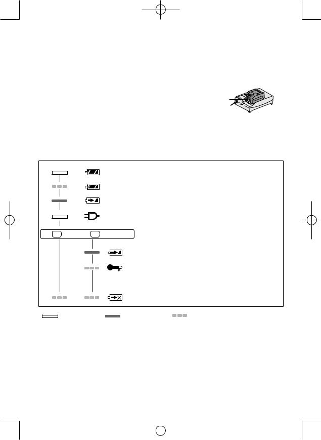
6.Falls die Akkutemperatur 0°C oder weniger beträgt, dauert der Ladevorgang bis zur vollen Aufladung des Akkus länger als die normale Ladezeit.
Selbst wenn der Akku voll aufgeladen ist, hat er nur etwa 50% der Leistung eines voll aufgeladenen Akkus bei normaler Betriebstemperatur.
7.Falls die Betriebslampe nicht unmittelbar nach dem Anschluss des Ladegeräts auf leuchtet oder die Ladekontrolllampe nach Ablauf der normalen Ladezeit nicht schnell in Grün blinkt, konsultieren Sie einen Vertragshändler.
8.Wird ein voll aufgeladener Akku erneut in das Ladegerät eingesetzt, leuchtet die Ladekontrolllampe auf. Nach einigen Minuten beginnt die Ladekontrolllampe rascher zu blinken und zeigt an, dass der Ladevorgang abgeschlossen ist.
9.Nehmen Sie den Akku bei angehobenem Akku-Entriegelungsknopfab.
Akku-
Entriegelungsknopf
ANZEIGELAMPEN
Ladevorgang ist abgeschlossen. (Volle Ladung)
Der Akku ist zu etwa 80 % aufgeladen.
Ladevorgang läuft.
Das Ladegerät ist an eine Netzsteckdose angeschlossen.
Ladebereitschaft hergestellt.
(Grün) |
(Orange) |
Ladezustandslampe. |
|
Links: Grün Rechts: Orange wird angezeigt. |
|||
|
|
Akku ist kalt.
Der Akku wird langsam geladen, um seine Belastung zu reduzieren.
Der Akku ist warm geworden.
Der Ladevorgang beginnt wieder, wenn dieTemperatur des Akku gefallen ist. Beträgt die Temperatur des Akkus –10°C oder weniger, beginnt die Ladekontrolllampe (orange) ebenfalls zu blinken. Der Ladevorgang beginnt, wenn die Temperatur des Akkus steigt.
Keine Ladung möglich. Verstaubt oder Defekt des Akkus.
Turn off |
Lit |
Flashing |
- 22 -
|
|
|
|
EY7546_EY7547_EY7550_EY7551_EU.indb 22 |
2011-2-25 14:40:15 |
||
|
|
|
|
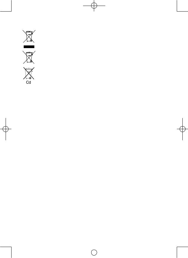
Benutzerinformation zur Sammlung und Entsorgung von veralteten Geräten und benutzten Batterien
Diese Symbole auf den Produkten, Verpackungen und/oder Begleitdokumenten bedeuten, dass benutzte elektrische und elektronische Produkte und Batterien nicht
in den allgemeinen Hausmüll gegeben werden sollen.
Bitte bringen Sie diese alten Produkte und Batterien zur Behandlung, Aufarbeitung bzw. zum Recycling gemäß Ihrer Landesgesetzgebung und den Richtlinien 2002/96/
EG und 2006/66/EG zu Ihren zuständigen Sammelpunkten.
Indem Sie diese Produkte und Batterien ordnungsgemäß entsorgen, helfen Sie dabei, wertvolle Ressourcen zu schützen und eventuelle negative Auswirkungen auf die menschliche Gesundheit und die Umwelt zu vermeiden, die anderenfalls durch eine
unsachgemäße Abfallbehandlung auftreten können.
Wenn Sie ausführlichere Informationen zur Sammlung und zum Recycling alter Produkte und Batterien wünschen, wenden Sie sich bitte an Ihre örtlichen Verwaltungsbehörden, Ihren Abfallentsorgungsdienstleister oder an die
Verkaufseinrichtung, in der Sie die Gegenstände gekauft haben.
Gemäß Landesvorschriften können wegen nicht ordnungsgemäßer Entsorgung dieses Abfalls Strafgelder verhängt werden.
Für geschäftliche Nutzer in der Europäischen Union
Wenn Sie elektrische oder elektronische Geräte entsorgen möchten, wenden Sie sich wegen genauerer Informationen bitte an Ihren Händler oder Lieferanten.
[Informationen zur Entsorgung in Ländern außerhalb der Euro päischen Union]
Diese Symbole gelten nur innerhalb der Europäischen Union. Wenn Sie solche Gegenstände entsorgen möchten, erfragen Sie bitte bei den örtlichen Behörden oder Ihrem Händler, welches die ordnungsgemäße Entsorgungsmethode ist.
Hinweis zum Batteriesymbol (unten zwei Symbolbeispiele):
Dieses Symbol kann in Kombination mit einem chemischen Symbol verwendet werden. In diesem Fall erfüllt es die Anforderungen derjenigen Richtlinie, die für die betreffende Chemikalie erlassen wurde.
IV. WARTUNG
Das Gerät nur mit einem trockenen, weichen Lappen abwischen. Verwenden Sie zum Reinigen keine feuchten Lappen oder flüchtige Lösungsmittel wie Farbverdünner oder Benzin.
V. ANZIEHDREHMOMENT
Die Kraft, die zum Anziehen eines Bolzens erforderlich ist, variiert je nach Bolzenmaterial und –größe sowie Material, auf dem verschraubt wird. Wählen Sie die Länge der Anziehzeit entsprechend aus.
Referenzwerte sind unten angegeben.
(Sie können je nach Anziehbedingungen variieren.)
Faktoren, die das Anziehdrehmoment beeinflussen
Das Anziehdrehmoment wird von einer Reihe Faktoren beeinflusst, einschließlich den folgenden. Nach dem Anziehen immer das Drehmoment mit einem Drehmomentschlüssel überprüfen.
1)Spannung
Wenn der Akku fast entladen ist, verringert sich die Spannung und das Anziehdrehmoment fällt ab.
-23 -
|
|
|
|
EY7546_EY7547_EY7550_EY7551_EU.indb 23 |
2011-2-25 14:40:15 |
||
|
|
|
|
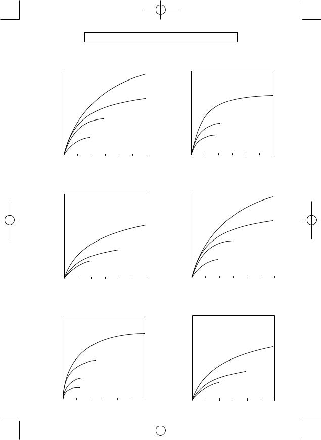
Bedingungen beim Festziehen von Bolzen
EY7546 |
M10 x 35 mm M12, M14, M16 x 45 mm |
|||||||||
|
N σ m |
|||||||||
|
(kgf-cm) |
|
|
|
|
Standardbolzen |
||||
|
196.0 |
|
|
|
|
|
|
|
|
|
|
2000 |
|
|
|
|
|
|
|
M16 |
|
|
|
|
|
|
|
|
|
|
|
|
Anziehdrehmoment |
147.0 |
|
|
|
|
|
|
|
|
|
1500 |
|
|
|
|
|
|
|
|
|
|
|
|
|
|
|
|
|
|
|
M14 |
|
|
98.0 |
|
|
|
|
|
|
|
|
|
|
1000 |
|
|
|
|
M12 |
|
|
|
|
|
|
|
|
|
|
|
|
|
|
|
|
49.0 |
|
|
|
|
|
|
|
|
|
|
500 |
|
|
|
M10 |
|
|
|
|
|
|
|
|
|
|
|
|
|
|
|
|
|
|
|
|
|
|
|
|
|
|
|
|
0.0 |
0.5 |
1.0 |
1.5 |
2.0 |
2.5 |
3.0 |
|||
EY7547
M8, M10 x 35 mm. M12 x 45 mm
N σ m HV-Schraube
(kgf-cm)
196.02000
Anziehdrehmoment |
147.0 |
|
|
|
|
|
|
|
|
|
|
|
|
|
|
|
|
||
500 |
|
|
|
|
|
|
|
||
|
1500 |
|
|
|
|
|
M12 |
||
|
98.0 |
|
|
|
|
|
|
|
|
|
1000 |
|
|
|
|
|
|
|
|
|
|
|
|
M10 |
|
|
|
|
|
|
49.0 |
|
|
|
|
|
|
|
|
|
|
M8 |
|
|
|
|
|
||
|
|
|
|
|
|
|
|
||
|
|
|
|
|
|
|
|
|
|
|
0.0 |
0.5 |
1.0 |
1.5 |
2.0 |
2.5 |
3.0 |
||
Anziehzeit (Sek.)
EY7546
M8, M10 x 35 mm. M12 x 45 mm
N σ m HV-Schraube
(kgf-cm)
196.02000
Anziehdrehmoment |
147.0 |
|
|
|
|
|
|
|
|
|
|
|
|
|
|
|
|
||
1500 |
|
|
|
|
|
|
|
||
|
|
|
|
|
|
|
|
M12 |
|
|
98.0 |
|
|
|
|
|
|
|
|
|
|
|
|
|
|
|
|
|
|
|
1000 |
|
|
|
|
|
|
|
|
|
49.0 |
|
|
|
|
M10 |
|
|
|
|
500 |
|
M8 |
|
|
|
|
|
|
|
|
|
|
|
|
|
|
|
|
|
|
|
|
|
|
|
|
|
|
|
0.0 |
0.5 |
1.0 |
1.5 |
2.0 |
2.5 |
3.0 |
||
Anziehzeit (Sek.)
EY7547
M10 x 35 mm M12, M14, M16 x 45 mm
N σ m Standardbolzen
(kgf-cm)
196.02000
|
|
|
|
|
|
|
|
M16 |
|
Anziehdrehmoment |
147.0 |
|
|
|
|
|
|
|
|
|
|
|
|
|
|
|
|
||
1500 |
|
|
|
|
|
|
|
||
|
|
|
|
|
|
|
|
||
|
98.0 |
|
|
|
|
|
|
|
|
|
1000 |
|
M14 |
|
|
|
|
|
|
|
|
|
|
|
|
|
|
|
|
|
49.0 |
|
|
|
|
|
|
|
|
|
500 |
M12 |
|
|
|
|
|
|
|
|
|
|
M10 |
|
|
|
|
|
|
|
|
|
|
|
|
|
|
|
|
|
0.0 |
0.5 |
1.0 |
1.5 |
2.0 |
2.5 |
3.0 |
||
|
|
|
|
|
Anziehzeit (Sek.) |
|
|
|
||
EY7550 |
M10 x 35 mm M12, M14, M16 x 45 mm |
|||||||||
|
N σ m |
|
|
|
|
Standardbolzen |
||||
|
(kgf-cm) |
|
|
|
|
|||||
|
196.0 |
|
|
|
|
|
|
|
|
|
|
2000 |
|
|
|
|
|
|
|
M16 |
|
|
|
|
|
|
|
|
|
|
|
|
Anziehdrehmoment |
147.0 |
|
|
|
|
|
|
|
|
|
|
|
|
|
|
|
|
|
|
||
1500 |
|
|
|
|
|
|
|
|
|
|
|
|
|
|
|
|
|
|
|
M14 |
|
|
98.0 |
|
|
|
|
|
|
|
|
|
|
1000 |
|
|
|
|
M12 |
|
|
|
|
|
|
|
|
|
|
|
|
|
|
|
|
49.0 |
|
|
|
|
|
|
|
|
|
|
|
|
|
|
|
|
|
|
|
|
|
500 |
|
|
|
M10 |
|
|
|
|
|
|
|
|
|
|
|
|
|
|
|
|
|
|
|
|
|
|
|
|
|
|
|
|
0.0 |
0.5 |
1.0 |
1.5 |
2.0 |
2.5 |
3.0 |
|||
Anziehzeit (Sek.)
EY7550
M8, M10 x 35 mm. M12 x 45 mm
N σ m HV-Schraube
(kgf-cm)
196.02000
Anziehdrehmoment |
147.0 |
|
|
|
|
|
|
|
|
|
|
|
|
|
|
|
|
||
1500 |
|
|
|
|
|
|
|
||
|
|
|
|
|
|
|
|
M12 |
|
|
98.0 |
|
|
|
|
|
|
|
|
|
|
|
|
|
|
|
|
|
|
|
1000 |
|
|
|
|
|
|
|
|
|
49.0 |
|
|
|
|
M10 |
|
|
|
|
|
|
|
|
|
|
|
|
|
|
500 |
|
M8 |
|
|
|
|
|
|
|
|
|
|
|
|
|
|
|
|
|
|
|
|
|
|
|
|
|
|
|
0.0 |
0.5 |
1.0 |
1.5 |
2.0 |
2.5 |
3.0 |
||
Anziehzeit (Sek.) |
- 24 - |
Anziehzeit (Sek.) |
|
|
|
|
|
|
EY7546_EY7547_EY7550_EY7551_EU.indb 24 |
2011-2-25 14:40:16 |
||
|
|
|
|
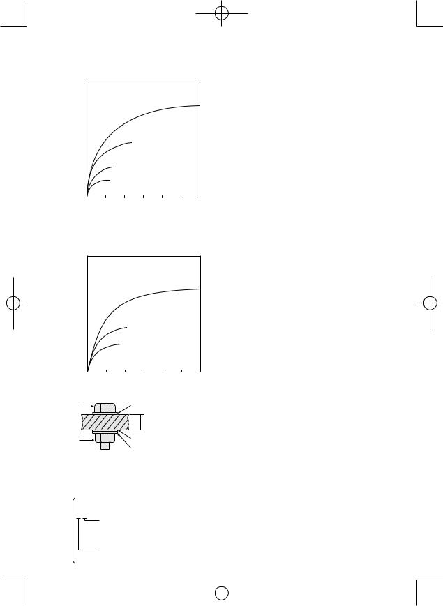
EY7551
M10 x 35 mm M12, M14, M16 x 45 mm
N σ m Standardbolzen
(kgf-cm)
196.02000
|
|
|
|
|
|
|
|
M16 |
|
Anziehdrehmoment |
147.0 |
|
|
|
|
|
|
|
|
|
|
|
|
|
|
|
|
||
1500 |
|
|
|
|
|
|
|
||
|
|
|
|
|
|
|
|
||
|
98.0 |
|
|
|
|
|
|
|
|
|
1000 |
|
M14 |
|
|
|
|
|
|
|
|
|
|
|
|
|
|
|
|
|
49.0 |
|
|
|
|
|
|
|
|
|
500 |
M12 |
|
|
|
|
|
|
|
|
|
|
M10 |
|
|
|
|
|
|
|
|
|
|
|
|
|
|
|
|
|
0.0 |
0.5 |
1.0 |
1.5 |
2.0 |
2.5 |
3.0 |
||
Anziehzeit (Sek.)
EY7551
M8, M10 x 35 mm. M12 x 45 mm
N σ m HV-Schraube
(kgf-cm)
196.02000
Anziehdrehmoment |
147.0 |
|
|
|
|
|
|
|
|
|
|
|
|
|
|
|
|
||
500 |
|
|
|
|
|
|
|
||
|
1500 |
|
|
|
|
|
M12 |
||
|
98.0 |
|
|
|
|
|
|
|
|
|
1000 |
|
|
|
|
|
|
|
|
|
|
|
|
M10 |
|
|
|
|
|
|
49.0 |
|
|
|
|
|
|
|
|
|
|
M8 |
|
|
|
|
|
||
|
|
|
|
|
|
|
|
||
|
|
|
|
|
|
|
|
|
|
|
0.0 |
0.5 |
1.0 |
1.5 |
2.0 |
2.5 |
3.0 |
||
2)Anziehzeit
Längere Anziehzeiten resultieren in einem erhöhten Anziehdrehmoment. Übermäßiges Anziehen ist nicht dienlich und reduziert die Lebensdauer des Werkzeugs.
3)Verschiedene Bolzendurchmesser
Die Maß des Bolzendurchmessers beeinflusst das Anziehdrehmoment.
Das Anziehdrehmoment steigt an, wenn der Bolzendurchmesser größer wird.
4)Anziehbedingungen
 Das Anziehdrehmoment variiert je nach Grad, Länge und Anziehkoeffizient sogar bei gleichen Bolzen (fester Koeffizient wird vom Hersteller bei der Produktion angegeben).
 Das Anziehdrehmoment variiert je nach Oberflächenbeschaffenheit auch bei gleichen Verschraubmaterialien (z. B. Stahl).
 Das Drehmoment wird drastisch redu ziert, wenn der Bolzen und die Mutter anfangen, sich zusammen zu drehen.
5)Buchsenspiel
Das Drehmoment wird gesenkt, sobald zum Anziehen eines Bolzens eine Sechskant-Konfiguration der Buchse mit falscher Größe verwendet wird.
6)Schalter (Betriebsschalter)
Das Drehmoment wird gesenkt, wenn nuverstäuolich Schalter der nicht gänzlich hineingedrückt wurde.
7)Wirkung des Anschlussadapters
Das Drehmoment wird gesenkt, wenn das Gerät mit unvollständig gedrücktem Schalter benutzt wird.
Anziehzeit (Sek.)
Bolzen |
Unterlegscheibe |
|
 Stahlblechdicke
 10 mm (3/8”)
Mutter |
Unterlegscheibe |
Federscheibe
Anziehbedingungen
•Die folgenden Bolzen werden verwendet.
Standardbolzen: Stärketyp 4,8 HV-Typ 12,9
Erläuterung des Stärketyps
4.8
 Bolzenstreckgrenze (80% der Zugfestigkeit) 32 kgf/mm2 (45000 psi)
 Bolzenzugfestigkeit 40 kgf/mm2 (56000 psi)
- 25 -
|
|
|
|
EY7546_EY7547_EY7550_EY7551_EU.indb 25 |
2011-2-25 14:40:16 |
||
|
|
|
|

VI. ZUBEHÖR
Verwenden Sie nur Bits der geeigneten Größe.
Optionales Original-Schnellwechselfutter von Panasonic (EY9HX110E). Spannfuttergröße: 6,35 mm hexadezimal
VII. ANHANG
MAXIMAL ZULÄSSIGE KAPAZITÄTEN
Modell |
|
EY7546 |
|
EY7547 |
EY7550 |
|
EY7551 |
Schrauben |
Holzschraube |
|
|
3,5 – |
9,5 mm |
|
|
Selbstbohrende |
|
|
|
|
|
|
|
eindrehen |
|
|
3,5 – |
6 mm |
|
||
Schraube |
|
|
|
||||
|
|
|
|
|
|
|
|
Schrauben anziehen |
|
Standardschraube: M6 – M16 |
|
||||
|
|
HV-Schraube: M6 – M12 |
|
||||
|
|
|
|
|
|||
VIII.TECHNISCHE DATEN
HAUPTGERÄT
Modell |
|
EY7546 |
EY7547 |
|
EY7550 |
EY7551 |
|
Motor |
|
14,4 V |
|
18 V |
|||
|
Modus „Schwach“ |
|
0 - 1000 min-1 |
(U/min) |
|
||
Drehzahl ohne Last |
Modus „Mittel“ |
|
0 - 1400 min-1 |
(U/min) |
|
||
|
Modus „Stark“ |
0 - 2500 min-1 (U/min) |
0 - 2300 min-1 (U/min) |
0 - 2500 min-1 (U/min) |
0 - 2300 min-1 (U/min) |
||
Maximales Drehmoment |
150 N·m (1330 kgf-cm) |
200 N·m (1770 kgf-cm) |
155 N·m (1370 kgf-cm) |
205 N·m (1815 kgf-cm) |
|||
Schlagzahl pro |
Modus „Schwach“ |
|
0 - 2000 min-1 |
(S/min) |
|
||
Modus „Mittel“ |
|
0 - 2800 min-1 |
(S/min) |
|
|||
Minute |
|
|
|
|
|
|
|
Modus „Stark“ |
0 - 3000 min-1 (S/min) |
0 - 3500 min-1 (S/min) |
0 - 3300 min-1 (S/min) |
0 - 3500 min-1 (S/min) |
|||
|
|||||||
Gesamtlänge |
|
143 mm (5-5/8˝) |
155 mm (6-1/8˝) |
143 mm (5-5/8˝) |
155 mm (6-1/8˝) |
||
Gewicht (mit Akku: EY9L44) |
1,5 kg (3,3Ibs) |
1,55 kg (3,4Ibs) |
|
— |
— |
||
Gewicht (mit Akku: EY9L50) |
— |
— |
1,6 kg (3.5Ibs) |
1,65 kg (3.6Ibs) |
|||
AKKU
Modell |
EY9L41 |
EY9L42 |
EY9L44 |
EY9L50 |
Akku |
|
|
Li-Ion-Akku |
|
Akkuspannung |
14,4 V DC (3,6 V × 4 Zellen) |
14,4 V DC (3,6 V × 8 Zellen) |
14,4 V DC (3,6 V × 10 Zellen) |
|
AKKU-LADEGERÄT
Modell |
|
EY0L81 |
|
|
Nennleistung |
Siehe Leistungsschild auf der Unterseite des Ladegerätes. |
|||
|
EY9L41 |
EY9L42 |
EY9L44 |
EY9L50 |
Ladezeit |
Nutzbar: 45 Min. |
Nutzbar: 30 Min. |
Nutzbar: 50 Min. |
|
|
Voll: 60 Min. |
Voll: 35 Min. |
Voll: 65 Min. |
|
HINWEIS: Diese Tabelle kann Modelle enthalten, die möglicherweise in Ihrem Wohngebiet nicht angeboten werden.
Bitte nehmen Sie auf den neusten Generalkatalog Bezug.
Name und Adresse des Händlers entnehmen Sie bitte der beiliegenden Garantiekarte.
|
|
|
|
EY7546_EY7547_EY7550_EY7551_EU.indb 26 |
2011-2-25 14:40:17 |
||
|
|
|
|
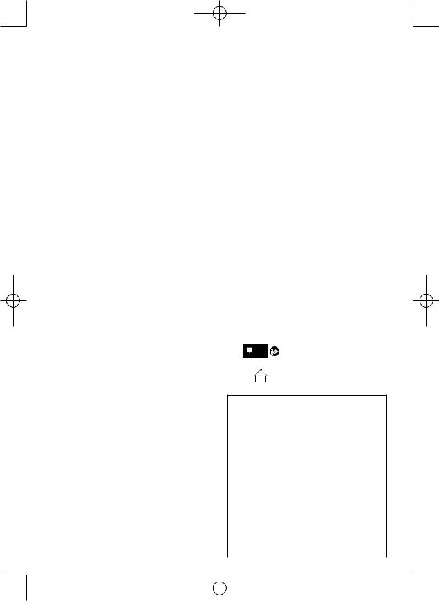
Instructions originales: anglais Traduction des instructions originales: Autres langues
Cet outil, en tant qu'unité complète avec sa batterie autonome, répond aux Degrés de Protection IP appropriés selon les normes IEC.
Définitions des codes IP
IP5X: L’entrée de poussière n’est pas complètement empêchée mais la poussière ne doit pas pénétrer au point de perturber le fonctionnement satisfaisant de l’outil ou d’en affecter la sécurité (Au cas où de la poudre de talc de moins de 75 μm s’introduirait à l’intérieur de l’outil).
IPX6: L’eau projetée en jets puissants contre l’outil de n’importe quelle direction ne doit pas avoir d’effets nuisibles (Au cas où approximativement 100 L/min d’eau à température normale est projetée sur l’outil a 3 mètre de distance pendant 3 minutes avec une lance de 12,5 mm de diamètre intérieur).
GARANTIE LIMITÉE
Le code IP56 rend possible un impact minimum d’eau et de poussière sur cet outil mais il n’en garantit pas les performances dans de telles conditions. Veuillez lire la notice d’utilisation et de sécurité pour plus de détails quant à un fonctionnement approprié.
Veuillez lire la brochure “Instructions de sécurité” et ce qui suit avant d’utiliser l’appareil.
I. REGLESDESECURITE COMPLEMENTAIRES
1)Portez des lunettes lorsque vous utilisez l’outil pendant de longues périodes.
2)N’oubliez pas que cet outil est toujours en état de fonctionner puisqu’il est alimenté par batterie.
3)Lors du perçage ou du vissage dans des murs, des planchers, etc., des câbles électriques sous tension peuvent être rencontrés. NE TOUCHEZ NI AU MANDRIN HEXAGONAL RAPIDE NI AUX PARTIES METALLIQUES DE L’OUTIL! Tenez l’outil au moyen de la poignée en matière plastique afin d’éviter toute secousse électrique si la mèche venait en contact avec un fil électrique.
4)NE manipulez PAS le levier d’inversion marche avant-marche arrière lorsque le commutateur de la gâchette est sur la position de marche. La batterie se déchargerait rapidement et l’appareil serait endommagé.
5)La température du chargeur peut s’élever en cours d’utilisation. Ce n’est pas là le signe d’une anomalie de fonctionnement. NE chargez PAS la batterie pendant une longue période.
6)Lorsque vous rangez ou transportez l’outil, mettez le levier d’inversion marche avantmarche arrière sur la position centrale (verrouillage du commutateur).
7)Ne forcez pas l’outil en maintenant la gâchette du contrôle de vitesse à micourse (commande de vitesse) pour arrêter le moteur.
Symbole |
Signification |
|||||||
|
|
V |
Volts |
|||||
|
|
|
|
|
|
|
|
|
|
|
|
|
|
|
|
Courant continu |
|
|
|
|
|
|
|
|
||
|
|
|
|
|
|
|
|
|
|
|
n0 |
Vitesse sans charge |
|||||
|
|
|
|
|
|
|
|
|
… min-1 |
Révolutions ou alternances par |
|||||||
minute |
||||||||
|
|
|
|
|
|
|
||
|
|
|
|
|
|
|
|
|
|
|
Ah |
Capacité électrique de la bat- |
|||||
|
|
terie autonome |
||||||
|
|
|
|
|
|
|
||
|
|
|
|
|
|
|
Lisez les instructions de |
|
|
|
|
|
|
|
|
fonctionnement avant |
|
|
|
|
|
|
|
|
l’utilisation. |
|
|
|
|
|
|
|
|
Pour l’utilisation à l’intérieur |
|
|
|
|
|
|
|
|
seulement. |
|
|
|
|
|
|
|
|
|
|
 AVERTISSEMENT:
•N’utilisez que la batterie autonome
Panasonic conçue pour l’utilisation avec cet outil rechargeable.
•Panasonic décline toute responsabilité en cas de dommage ou d’accident causé par l’utilisation d’une batterie autonome recyclée ou de contrefaçon.
•Ne mettez pas la batterie autonome au rebut dans un feu ou ne l’exposez pas à une chaleur excessive.
•N’enfoncez pas de clous ou autres dans la batterie autonome, ne la soumettez pas à des chocs, ne la démontez pas ou n’essayez pas de la modifier.
•Ne laissez pas d’objets métalliques entrer en contact avec les bornes de la batterie autonome.
- 27 -
|
|
|
|
EY7546_EY7547_EY7550_EY7551_EU.indb 27 |
2011-2-25 14:40:17 |
||
|
|
|
|
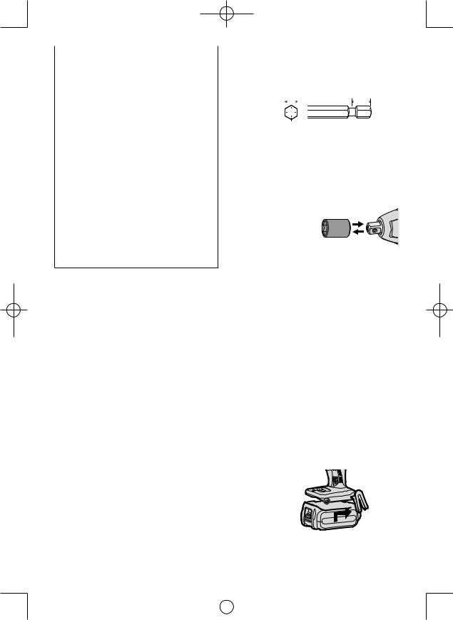
•Ne transportez pas ou ne rangez pas la batterie autonome dans un récipient contenant des clous ou tout autre objet métallique.
•Ne chargez pas la batterie autonome dans un endroit où la température est élevée comme à proximité d’un feu ou à la lumière directe du soleil. Sinon la batterie peut surchauffer, prendre feu ou exploser.
•N’utilisez que le chargeur dédié pour charger la batterie autonome. Sinon, la batterie peut fuir, surchauffer ou exploser.
•Après avoir retiré la batterie autonome de l’outil ou du chargeur, remettez toujours le couverclede la batterie autonome en place. Sinon, les contacts de la batterie peuvent se mettre en court-circuit, entraînant le risque d’un incendie.
•Si la batterie autonome s’est détériorée, la remplacer par une batterie neuve. L’utilisation prolongée d’une batterie autonome endommagée peut provoquer des dégagements de chaleur, un départ de feu ou l’explosion de la batterie.
II. MONTAGE
Fixation ou retrait d’une mèche
REMARQUE:
•Lors de l’installation ou de l’enlèvement d’une mèche, débranchez la batterie autonome de l’outil ou placez le commutateur sur la position centrale (verrouillage du commutateur).
1.Maintenez le collier du mandrin de connexion rapide et retirez-le de la perceuse.
2.Insérez la mèche dans le mandrin. Relâchez le collier.
3.Le collier reviendra dans sa position d’origine lorsqu’il sera relâché.
4.Tirez sur la mèche pour vérifier qu’elle ne ressort pas.
5.Pour retirer la mèche, tirez le collier vers l’extérieur de la même manière.
MISE EN GARDE:
•Si le collier ne revient pas dans sa position d’origine ou si la mèche ressort lorsque vous tirez dessus, cela signifie que la mèche n’a pas été fixée correctement. Assurez-vous que la mèche est bien fixée avant toute utilisation.
Utilisez des mèches hexagonales de 6,35 mm (1/4”).
Pour assurez une fixation correcte des mèches, n’utilisez que des mèches hexa gonales avec une détente de 9,5 mm (3/8”).
6.35 mm (1/4") |
9.5 mm (3/8") |
|||||||||
|
|
|
|
|
|
|
|
|
|
|
|
|
|
|
|
|
|
|
|
|
|
|
|
|
|
|
|
|
|
|
|
|
|
|
|
|
|
|
|
|
|
|
|
|
|
|
|
|
|
|
|
|
|
|
|
|
|
|
|
|
|
|
|
|
|
Fixation ou retrait de la douille
1.Fixation de la douille
Fixez la douille en faisant coulisser la détente femelle du fond de la douille sur l’entraînement carré du corps.
Assurez-vous que que la douille est bien raccordée au corps.
2.Pour retirer la douille
Tirez la douille vers l’extérieur.
REMARQUE:
Fixation et retrait des options et douilles originales
Maintenez le corps au-dessus du point de congélation (0ºC, 32ºF) lors de la fixation ou du retrait des options et des douilles originales à/de l’entraînement carré du corps. Le coussinet en caout chouc de l’entraînement carré destiné à repousser la boule peut se durcir au point de congélation. Cela exige plus de force pour retirer et fixer les douilles.
Fixation ou retrait de la bat terie autonome
1.Pour raccorder la batterie autonome: Alignez les marques d’alignement et fixez la batterie autonome.
•Faites glisser la batterie autonome jus qu’à ce qu’elle se verrouille en position.
Marques 
 d’alignement

2.Pour retirer la batterie autonome:
Tirez sur le bouton depuis l’avant pour libérer la batterie autonome.
- 28 -
|
|
|
|
EY7546_EY7547_EY7550_EY7551_EU.indb 28 |
2011-2-25 14:40:18 |
||
|
|
|
|
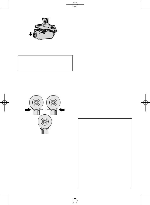
Bouton 

III. FONCTIONNEMENT
 AVERTISSEMENT!
•Ne respirez pas la fumée dégagée par l’outil ou la batterie, car elle pourrait être nocive.
[Corps principal]
Utilisation du commutateur et du levier d’inversion marche avant-marche arrière
Rotation en |
Rotation en |
sens normal |
sens inverse |
Verrouillage du commutateur
MISE EN GARDE:
Pour prévenir tout dégât, n’actionnez pas le levier d’inversion marche avantmarche arrière tant que la mèche n’a pas complètement terminé de tourner.
Utilisation du commutateur pour une rotation en sens normal
1.Poussez le levier pour obtenir une rotation en sens normal.
2.Appuyez légèrement sur la gâchette pour que l’outil commence à tourner lentement.
3.La vitesse augmente à mesure où la gâchette est enfoncée pour un vissage efficace des vis. Le frein fonctionne et la mèche s’arrête immédiatement dès que la gâchette est relâchée.
4.Ramenez le levier en position centrale lorsque vous n’utilisez plus l’outil (verrouil lage du commutateur).
Utilisation du commutateur de rotation en sens inverse
1.Poussez le levier pour obtenir une rotation en sens inverse. Avant d’utiliser l’outil, vérifiez le sens de rotation.
2.Appuyez légèrement sur la gâchette pour que l’outil commence à tourner lentement.
3.Ramenez le levier en position centrale lorsque vous n’utilisez plus l’outil (ver rouillage du commutateur).
MISE EN GARDE:
•Pour empêcher toute élévation exces sive de la température de la surface de l'outil, n'utilisez pas l'outil de façon continue en utilisant deux batteries autonomes ou plus. L'outil a besoin de se refroidir pendant un certain temps avant d'être connecté à une autre batterie autonome.
Comment utiliser le crochet de ceinture
 AVERTISSEMENT!
•Assurez-vous de bien accrocher le crochet de ceinture à l’unité principale en serrant bien la vis. Si le crochet de ceinture n’est pas bien fixé à l’unité principale, le crochet peut se décrocher et l’unité peut tomber.
Cela pourrait entraîner un accident ou des blessures.
•Vérifiez régulièrement le serrage de la vis.
Si elle est desserrée, resserrez-la bien.
•Assurez-vous d’accrocher fermement et de manière sûre le crochet de ceinture sur une ceinture de taille ou une autre ceinture. Faites attention que l’appareil ne glisse pas de la ceinture. Cela pourrait entraîner un accident ou des blessures..
•Lorsque l’unité principale est tenue par le crochet de ceinture, évitez de sauter ou de courir. Le crochet pourrait glisser et l’unité principale pourrait tomber.
Cela pourrait entraîner un accident ou des blessures.
- 29 -
|
|
|
|
EY7546_EY7547_EY7550_EY7551_EU.indb 29 |
2011-2-25 14:40:18 |
||
|
|
|
|
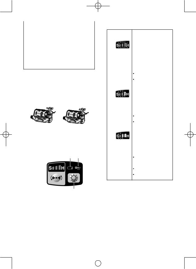
•Lorsque le crochet de ceinture n’est pas utilisé, assurez-vous de le remettre dans sa position de stockage. Le crochet pourrait se prendre dans quelque chose.
Cela pourrait entraîner un accident ou des blessures.
•Lorsque l’appareil est accroché à la taille par le crochet de ceinture, ne fixez pas de mèche autre qu’une mèche de serrage sur l’appareil. Un objet pointu tel qu’une mèche de perçage pourrait entraîner un accident ou des blessures.
Pour changer le côté d’instal lation du crochet de ceinture
Le crochet de ceinture peut être fixé sur les deux côtés de l’appareil.
1.Retrait du crochet
(1)Retirez la vis.
(2)Sortez le crochet.
2.Fixation du crochet sur l’autre côté
(1)Insérez le crochet de l’autre côté.
(2)Serrez complètement la vis pour qu’elle reste fermement en place.
Panneau de commande
(4) (3)
(1)
(2)
(1)Sélection du mode de puissance de percussion
 Sélection de la puissance de percussion entre 3 modes (Doux, Moyen, Dur).
Appuyez sur le bouton du mode de puissance de percussion. Le mode change à dur, moyen ou doux à chaque pression sur le bouton.
La perceuse est préréglée sur le réglage de mode de percussion “dur” à l’expédition de chez la fabricant.
Tableau de référence des travaux recommandés
Affichage du mode
de puissance de Application recommandée percussion
H |
Travaux nécessitant un |
|
couple de serrage élevé où |
||
il n’ y a pas de possibilité |
||
|
que les boulons ou la vis |
|
|
se cassent, que la tête soit |
|
0 - 2300 t/mn/ |
cisaillée ou que la mèche se |
|
desserre. (Ce réglage offre le |
||
0 - 2500 t/mn |
||
couple de serrage maximum.) |
||
et |
Les applications convenant |
|
0 - 3000 p/mn/ |
comprennent: |
|
0 - 3300 p/mn/ |
Serrage de boulons M8 et |
|
0 - 3500 p/mn |
plus gros |
|
Serrage de vis longues |
||
|
||
|
pendant des travaux de |
|
|
finition intérieure |
|
M |
Travaux nécessitant un |
|
couple de serrage limité où |
||
il est possible que la vis se |
||
|
casse ou que la tête soit |
|
|
cisaillé . (Ce réglage limite |
|
|
le couple de serrage.) Les |
|
0 - 1400 t/mn |
applications convenant |
|
et |
comprennent: |
|
Serrage de boulons d’un |
||
0 - 2800 p/mn |
||
diamètre inférieur (M6) |
||
|
||
|
Serrage de vis à métal |
|
|
lors de l’installation |
|
|
d’accessoires |
|
S |
Travaux nécessitant un |
|
couple de serrage limité où |
||
il est possible que la vis se |
||
|
casse, que la tête soit cisaillé |
|
|
ou que la mèche se desserre. |
|
|
(Ce réglage limite le couple |
|
|
de serrage.) Les applications |
|
0 - 1000 t/mn |
convenant comprennent: |
|
Serrage de boulons d’un |
||
et |
diamètre inférieur à M6 |
|
0 - 2000 p/mn |
pouvant être facilement |
|
|
cisaillés |
|
|
Serrage de vis dans du |
|
|
plastique moulé |
|
|
Installation de panneaux |
|
|
muraux en plâtre |
* p/mn.: percussions par minute
Évitez d’enfoncer à plusieurs reprises le commutateur lorsque les boulons et les vis sont solidement attachés.
Vous risqueriez autrement de retarder le démarrage de la rotation ou de provoquer le clignotement de l’affichage du mode de puissance de percussion et d’empêcher par là le démarrage de la rotation par mesure de protection du circuit.
- 30 -
|
|
|
|
EY7546_EY7547_EY7550_EY7551_EU.indb 30 |
2011-2-25 14:40:18 |
||
|
|
|
|
 Loading...