


EYFR04 User Manual
v4.0
21 July 2017

Table of Contents |
|
|
Quick Start ...................................................................................................................................... |
|
4 |
Chapter 1: Overview ....................................................................................................................... |
|
8 |
Warnings ..................................................................................................................................... |
|
9 |
Cautions ...................................................................................................................................... |
|
9 |
Unit Overview........................................................................................................................... |
|
10 |
Compatible Tools...................................................................................................................... |
|
10 |
Chapter 2: Using the unit .............................................................................................................. |
|
11 |
Concepts.................................................................................................................................... |
|
12 |
Run Screen ................................................................................................................................ |
|
13 |
History....................................................................................................................................... |
|
14 |
Unit Status................................................................................................................................. |
|
15 |
Network Status.......................................................................................................................... |
|
15 |
Tool Status ................................................................................................................................ |
|
16 |
Chapter 3: Configuring the unit .................................................................................................... |
|
17 |
Introduction............................................................................................................................... |
|
18 |
Saving Configuration Changes ................................................................................................. |
|
18 |
Entering letters .......................................................................................................................... |
|
18 |
Main Menu................................................................................................................................ |
|
19 |
Tools ......................................................................................................................................... |
|
20 |
Parameters................................................................................................................................. |
|
23 |
Jobs ........................................................................................................................................... |
|
25 |
Network Settings....................................................................................................................... |
|
28 |
Qualifier Settings ...................................................................................................................... |
|
29 |
Channel Change ........................................................................................................................ |
|
36 |
Events........................................................................................................................................ |
|
36 |
Network Log ............................................................................................................................. |
|
37 |
Chapter 4: Serial Communications ............................................................................................... |
|
38 |
Introduction............................................................................................................................... |
|
39 |
Barcode ..................................................................................................................................... |
|
39 |
Serial Printer ............................................................................................................................. |
|
42 |
EYFR04 User Manual |
2 of 76 |
v4.0 |
|
|
21 July 2017 |
Chapter 5: Discrete I/O ................................................................................................................. |
43 |
Introduction............................................................................................................................... |
44 |
Discrete I/O Specifications ....................................................................................................... |
44 |
Assigning I/O Functions ........................................................................................................... |
47 |
I/O Status .................................................................................................................................. |
47 |
Inputs......................................................................................................................................... |
47 |
Outputs...................................................................................................................................... |
51 |
Chapter 6: Atlas Copco Open Protocol......................................................................................... |
54 |
Introduction............................................................................................................................... |
55 |
Using Groups with Atlas Copco Open Protocol ....................................................................... |
55 |
Configuration Options .............................................................................................................. |
55 |
Supported Commands............................................................................................................... |
58 |
Unsupported Commands........................................................................................................... |
59 |
Chapter 7: EtherNet/IPTM.............................................................................................................. |
61 |
Chapter 8: ToolsNet ...................................................................................................................... |
66 |
Introduction............................................................................................................................... |
67 |
Configuration Options .............................................................................................................. |
67 |
Chapter 9: Data Management ....................................................................................................... |
70 |
Download data to USB ............................................................................................................. |
71 |
Upload USB file to device ........................................................................................................ |
72 |
Chapter 10: Firmware Updates ..................................................................................................... |
73 |
Chapter 11: Product Specifications............................................................................................... |
75 |
Dimensions ............................................................................................................................... |
76 |
Radio Information ..................................................................................................................... |
76 |
EYFR04 User Manual |
3 of 76 |
v4.0 |
|
|
21 July 2017 |

Quick Start
EYFR04 User Manual |
4 of 76 |
v4.0 |
Quick Start |
|
21 July 2017 |
This quick start will guide you through the process of configuring the unit for first time use.
Plug the provided power cable into the unit and 100-240 VAC power and turn on the power switch. The beeper will sound a series of quick beeps and the display will show the loading progress.
Once loading is completed, the unit should go to the Run screen. If the unit stays on the loading screen with an error, please contact support.
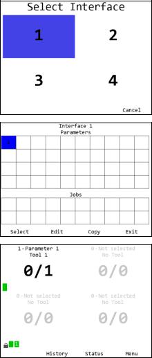
To use a tool with the qualifier, you must first “learn” the tool to the qualifier. To do so, press the button below
Menu.
Enter the password (1011 by default) using the numeric keypad and press ENT when completed.
In the menu, press the right arrow to select Tools and press
ENT.
EYFR04 User Manual |
5 of 76 |
v4.0 |
Quick Start |
|
21 July 2017 |
In the tools menu, press ENT to go to the main tools page.
If the tool you are going to learn to the qualifier has previously been used with another unit, make sure that unit is off before continuing. Press the button beneath Learn to begin the learn process.
Follow the directions on screen to learn the tool.
The unit will return to the Tools screen with the just learned tool now with a tool name of “Tool 1” instead of “No Tool”.
Return to the menu by pressing ESC or the button below Exit. Then press ENT to go to the Parameters screen.
EYFR04 User Manual |
6 of 76 |
v4.0 |
Quick Start |
|
21 July 2017 |
To run a tool, you must activate a parameter that uses the tool. When learned, a tool is automatically associated with the parameter of the same number. If you are following this guide with a new unit, you should have just learned Tool 1, which can be run by Parameter 1.
Press the button below Select to select Parameter 1.
You will be returned to the Run screen, now with Parameter 1 selected. You can now perform tightenings with Tool 1 that will be monitored, stored, and reported by the qualifier.
EYFR04 User Manual |
7 of 76 |
v4.0 |
Quick Start |
|
21 July 2017 |

Chapter 1: Overview
EYFR04 User Manual |
8 of 76 |
v4.0 |
Chapter 1: Overview |
|
21 July 2017 |

Warnings
Do not disassemble the unit for repair or modifications. There is a high electrical voltage inside the unit that could cause electric shock.
Do not allow any type of liquid to come into contact with any part of the unit.
Insert all fittings fully into their mating receptacles. Failure to do so could result in injury.
Do not fold, bend, or apply excessive force to any cable or fitting.
Cautions
Please use caution when handling this or any other electrical appliance.
This unit accepts an AC input voltage from 100-240 VAC. Trying to operate this unit with a voltage outside that range may cause damage to the unit.
Avoid placing or storing this unit in a location where it may become wet or dust covered.
Do not place or mount this unit in an unstable area.
Dropping this unit may result in personal injury or damage to the unit.
Before performing any maintenance on the unit, make sure to turn it off and remove the power cable.
There are no user serviceable parts inside the main enclosure of the unit.
EYFR04 User Manual |
9 of 76 |
v4.0 |
Chapter 1: Overview |
|
21 July 2017 |

Unit Overview
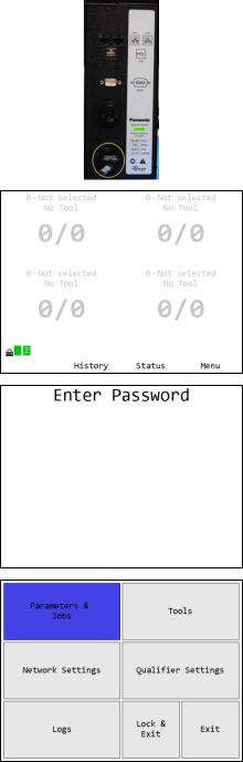
The EYFR04 is equipped with a color LCD display, four soft keys immediately below the LCD, a numeric keypad with decimal point, navigation keys, and enter and escape buttons. The current function of the soft keys is indicated at the bottom of the LCD above the button.
The left side of the EYFR04 has two RJ-45 Ethernet ports to allow it to be used in a chain network configuration.
The USB-A connector is used to provide firmware updates via a standard USB drive.
The RS232 DSUB9 connector can be used with a serial bar code reader.
The beeper provides an audio indication for any combination of accepts, rejects, and batch completions. The beeper volume can be adjusted through the user interface. (See the Qualifier Settings section in the next chapter.)
The power plug accepts 100-240 VAC at 50-60 Hz.
The right side of the EYFR04-A has a 24-pin discrete I/O connector. This connector is not available on the EYFR04-B model.
Both models have a 5-pin remote connector that connects to other devices that provide additional I/O capabilities.
Compatible Tools
The EYFR04 works with the following models of tools: |
|
|
||||
|
EYFGA1NR |
|
EYFLA5AR |
|
EYFLA6PR |
|
|
EYFLA5PR |
|
EYFMA1JR |
|||
|
EYFGA2NR |
|||||
|
EYFLA5QR |
|
EYFMA1PR |
|||
|
EYFGA3NR |
|||||
|
EYFLA6JR |
|
|
|||
|
EYFLA4AR |
|
|
|||
|
|
|
|
|||
EYFR04 User Manual |
10 of 76 |
v4.0 |
Chapter 1: Overview |
|
21 July 2017 |
Chapter 2: Using the unit
EYFR04 User Manual |
11 of 76 |
v4.0 |
Chapter 1: Overview |
|
21 July 2017 |
Concepts
Interfaces
The EYFR04 has 4 interfaces. Interfaces within the EYFR04 work almost like having 4 logical qualifiers inside the single physical qualifier. Some settings, such as IP Address and beeper settings, are shared between the interfaces. Each interface has its own parameters and jobs as well as its own tightening log and can be controlled separately by a plant control system.
Tools
The EYFR04 works with up to 16 Panasonic battery tools at a time. To use a tool with the qualifier, you must first “learn” the tool to the qualifier. The process to do this is described in the Quick Start.
Tools are not activated directly by the unit. Instead, they are activated when a parameter that uses the tool is running. Tools are automatically used by the parameter of the same number (Parameter 1 always uses Tool 1, Parameter 2 always uses Tool 2, etc.). A tool may additionally be used by any number of Parameters 17-100 but may not be assigned to any Parameter 1-16 other than the matching parameter to which it is automatically assigned.
The EYFR04 can store some information about when calibration or preventative maintenance should occur. These are set up in the Tool Configuration screen, which is described in the next chapter.
For tools with the appropriate firmware and setup, the unit will use the enable/disable or antitheft feature to only allow the tool to run when a parameter that uses it is active.
Parameters
Parameters are the basic unit of operation for the EYFR04. A parameter contains a tool to run and some settings to use with it, such as the batch size. The EYFR04 supports 40 parameters per interface. Each parameter must be associated with one of the tools learned to the unit before it can be run. Parameters 1-16 in each interface will always be associated with the tool of the same number, and the other parameters may be used to operate a tool with different settings. Because a tool is only assigned to a single interface at a time, this means that only one interface at a time, the one to which the tool is assigned, can select a parameter that is locked to a given tool.
Jobs
Jobs are the top level of operation in the EYFR04, made up of multiple parameters that must all run together in a sequence. The EYFR04 supports 20 jobs per interface with up to 30 steps each. A job will only use parameters belonging to the same interface as the job. A job may have multiple parameters that use the same tool or even the same parameter multiple times. When defining a job, you may override the batch count for parameter steps in the job.
EYFR04 User Manual |
12 of 76 |
v4.0 |
Chapter 1: Overview |
|
21 July 2017 |

Run Screen
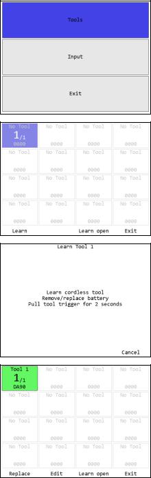
The Run screen shows which parameters the unit is currently running.
Figure 1: Run Screen
Tightening Notifications
Every time a tightening is received from a running tool, the background of the area of the screen showing the current parameter and batch count for the tool will be shaded with a color indicating the status of the tightening.
Red – A rejected tightening occurred.
Green – An accepted tightening occurred that did not complete a batch.
Blue – An accepted tightening occurred that completed a batch. If the qualifier NOKs setting is set to Count, this further indicates that no rejected tightenings were counted towards this batch.
Yellow – An accepted or rejected tightening occurred that completed a batch. This color will only occur when the qualifier NOKs setting is set to Count and one or more rejected tightenings were counted towards the current batch.
Tool Status Codes
The tool status indicator for each active parameter shows the status of the tool for the parameter. When the tool is ready to run, the indicator should be green with no number. If the tool is not ready to run or a warning or error condition occurs, the indicator will change to yellow for a warning or red for an error and display a code to indicate the tool condition. The possible codes are:
Code |
Color |
Meaning |
1 |
Red |
Tool has not communicated with the unit since power-up |
2 |
Yellow |
Enabling or disabling tool |
2 |
Red |
Tool enable or disable failed |
3 |
Yellow |
Tool is disabled |
5 |
Yellow |
Radio signal strength is below recommended level for best performance |
5 |
Red |
Radio signal strength is below recommended minimum level for use |
6 |
Yellow |
Tool requires calibration |
7 |
Yellow |
Tool requires preventative maintenance |
EYFR04 User Manual |
13 of 76 |
v4.0 |
Chapter 1: Overview |
|
21 July 2017 |
Unit Radio Status Indicator
The unit radio status indicator shows the status of the radio in the unit. In normal use, the indicator should be green with no number. If the radio is not working correctly, the indicator will be red with an error code.
Network Status Indicator
The network status indicator shows the status of the Ethernet ports on the unit. When the Ethernet is used, the indicator will be green and show the number of currently active network connections. If no Ethernet cable is plugged into either port, the indicator will be yellow. If the network initialization fails, the indicator will be red and show an error code. The Network Status screen shows more detailed information.
History
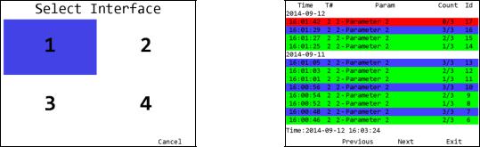
Figure 2: Select Interface screen |
Figure 3: History screen |
Soft keys
1.No function
2.Previous – Go to the previous page of more recent tightenings. When on the first page, this key will be blank.
3.Next [ENT] – Go to the next page of older tightenings. When on the last page, this key will be blank.
4.Exit [ESC] – Returns to the Run screen.
The History screen shows some information about the tightenings stored in unit memory. More information about the tightenings is not shown but is available via the network protocols. This screen shows:
Time – The time the tightening occurred. The date is indicated at the top of the table and each time it changes in a white row. The current time is shown at the bottom of the screen for comparison.
T# – The tool number that produced the tightening
Param – The number and name of the parameter that produced the tightening
Count – The current batch count and batch size for the tightening
Id – The tightening id number. This screen shows only the last 4 digits of the id number; additional digits may be present in the network commands.
EYFR04 User Manual |
14 of 76 |
v4.0 |
Chapter 1: Overview |
|
21 July 2017 |

Unit Status
Figure 4: Unit Status screen
Soft keys
1.I/O – Go to the I/O Status screen (see Chapter 5: Discrete I/O).
2.Network – Go to the Network Status screen.
3.Tool – Go to the Tool Status screen.
4.Exit [ESC] – Returns to the Run screen.
The Unit Status screen shows some basic information about the current unit configuration that may be useful for diagnostics purposes.
The average signal strength is for all tools learned to the unit and should be from 0 to -70 dBm. If the signal strength is weaker, the unit may have frequent slow or failed communication. To improve the signal strength, try bringing the unit and tools closer together, changing the XBEE channel, or reducing sources of interference from the environment.
Last barcode shows the command number of the last bar code scanned (see Chapter 4: ) or an error if the last attempt bar code could not be processed. Interface 1-4 VIN show what will be included with tightenings for each interface.
Network Status
Figure 5: Network Status screen
The network status screen shows the current Ethernet status of the unit. The MAC address is assigned by the factory and cannot be changed. The IP address, subnet mask, and gateway may be edited from the Network Settings - General screen or assigned via DHCP.
The Ethernet 1 and 2 lines indicate if a physical cable connection is detected on the corresponding Ethernet ports of the unit. If no connection on a port is detected, the unit will show “Not connected”. If a connection is detected, the baud rate and duplex of the connection will be listed.
The rest of the screen shows some basic information about the active Ethernet connections. For each connection, this page shows the source address, time of the last packet on the connection, which interface the connection is to, and some protocol specific information, such as last MID received or which EtherNet/IPTM connection points are being used.
EYFR04 User Manual |
15 of 76 |
v4.0 |
Chapter 1: Overview |
|
21 July 2017 |
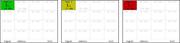
Tool Status
Figure 6: Tool Status - Good Signal |
Figure 7: Tool Status – Low Signal |
Figure 8: Tool Status - Bad Signal |
Soft keys
1.Signal – Show the signal strength of each tool.
2.Address – Show the address of each tool
3.No function
4.Exit [ESC] – Returns to the Unit Status screen.
The Tool Status screen shows the status of the tools learned into the unit. This screen shows the signal strength of the last packet from the tool but can also show the radio address of the tools.
For signal strength, a less negative number indicates a better signal (-50 dBm is better than -60 dBM). The screen shows a color based on the quality of the signal.
Green – The signal from this radio is strong and will work at best performance.
Yellow – The signal from the radio is weaker than recommended for best performance. The radio should work but may have slower or occasionally interrupted communication with the unit.
Red – The signal from the radio is weaker than recommended for any use. The radio may successfully transmit some results but will frequently have slow or failed communication with the unit. If only one tool is red, bring it and unit closer together. If multiple tools are red, consider using a different radio channel (changed from the Qualifier Settings screen).
EYFR04 User Manual |
16 of 76 |
v4.0 |
Chapter 1: Overview |
|
21 July 2017 |

Chapter 3: Configuring the unit
EYFR04 User Manual |
17 of 76 |
v4.0 |
Chapter 3: Configuring the unit |
|
21 July 2017 |
Introduction
All of the features of the EYFR04 can be configured directly on the unit, except the I/O and remote device configuration. The configuration, along with parameter and job selection is available from the unit menu. The menu is available from the Run screen by pressing soft key 4 or ENT.
The navigation keys are used primarily to move from entry to entry on a screen. The numeric keypad is used for any data entry and occasionally to assist in navigation. When describing the soft keys for a screen, [ENT] or [ESC] will be listed next to the a key if the ENT or ESC buttons perform the same operation. The ESC key is generally used to cancel changes or exit a screen without performing an action.
Saving Configuration Changes
Configuration editing screens will always have Save as soft key 3 and Cancel as soft key 4. You may also press ESC for Cancel. If you enter a screen and have not made any changes or do not want to save the changes you have made, press Cancel. To commit changes, press Save. Even if you have not made any changes, saving will update the last modified time for the item.
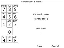
Entering letters
The unit has a special screen that allows using the numeric keypad to enter letters for fields that allow them, such as a parameter name. To get to this screen, press [ENT] when the cursor is on a row with such a field. Lowercase letters cannot be entered from the unit but can be entered through the PC software application.
The left side of this screen shows the letters associated with each number. Pressing a number repeatedly will cycle through the letters associated with the number followed by the number itself. Pressing a different number will commit the character to the new value and add the first letter
associated with the new number pressed. Pressing the left arrow will remove the last entered character. Pressing the up arrow will toggle between entering letters and numbers or just numbers.
Pressing the right arrow will commit the current character and move to the next position. You do not have to use the right arrow for every letter. However, there are two situations when you must use the right arrow. The first is to enter a blank space, which is accomplished by pressing the right arrow twice in a row. The second is to enter a name with two letters in a row associated with the same number. For example, to enter “Tool 1”, you would need to press the following sequence of keys:
|
Key |
|
New name |
|
|
8 |
|
T |
|
|
|
|
|
|
|
6 |
|
TM |
|
|
|
|
|
|
|
6 |
|
TN |
|
|
|
|
|
|
|
6 |
|
TO |
|
|
|
|
|
|
|
right arrow |
TO_ |
|
|
|
|
|
|
|
EYFR04 User Manual |
18 of 76 |
v4.0 |
||
Chapter 3: Configuring the unit |
|
|
21 July 2017 |
|
6 |
TOM |
|
|
6 |
TON |
|
|
6 |
TOO |
|
|
5 |
TOOJ |
|
|
5 |
TOOK |
|
|
5 |
TOOL |
|
|
right arrow |
TOOL_ |
|
|
right arrow |
TOOL _ |
|
|
1 |
TOOL 1 |
|
|
(Since neither 1 nor 0 have associated letters, pressing them will only enter the number.)
Once you have entered the desired name, press Save or ENT. This does not permanently save the value just entered. You must also save from the screen that sent you to the letter screen. If you no longer want to change the value, press Cancel or ESC. At this point, the unit will return to the previous screen without changing the value.
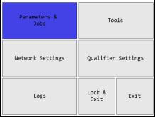
Main Menu
Figure 10: Main Menu
The EYFR04 menu provides the entry point to configure and control the unit. You must enter the box password before entering the menu from the Run screen. If you cannot remember the password, you may reset it to the factory default (1011) by entering the sequence “6853.48” on the Run screen. Use the arrow keys to navigate to the desired entry and press ENT to go to the entry’s screen. To exit the menu, press ESC or navigate to Lock & Exit or Exit and press ENT. Pressing ESC or Lock & Exit will “lock” the menu and return to the Run screen, requiring the password to be reentered before the menu can be accessed again. Pressing Exit will return to the Run screen without locking the unit, allowing the menu to be reentered without entering the password.
EYFR04 User Manual |
19 of 76 |
v4.0 |
Chapter 3: Configuring the unit |
|
21 July 2017 |

Tools
Figure 11: Main menu - Tools
Figure 13: Learned tool selected
Figure 12: Tools Menu
Figure 14: Empty slot selected
Soft keys
Tools may be highlighted by using the arrow keys to move the highlight to the desired tool or typing the number of the desired tool.
When a learned tool is highlighted, the soft keys are:
1.Replace – Learn a new tool in place of the current tool in this slot. If you cancel out of the learn sequence, the current tool will remain in the slot.
2.Edit [ENT] – Go to the Tool Configuration screen for the selected tool.
3.Learn open – Starts the learn sequence for the empty tool slot with the lowest number.
4.Exit [ESC] – Returns to the Main Menu screen.
When an empty tool slot is highlighted, the soft keys are:
1.Learn [ENT] – Starts the learn sequence for the highlighted tool slot.
2.No function
3.Learn open – Starts the learn sequence for the empty tool slot with the lowest number.
4.Exit [ESC] – Returns to the Main Menu screen.
EYFR04 User Manual |
20 of 76 |
v4.0 |
Chapter 3: Configuring the unit |
|
21 July 2017 |
Tool Configuration
Figure 15: Tool Configuration screen |
Figure 16: Tool Configuration screen – Input tools |
Soft keys
1.Forget – Removes the tool from the unit.
2.No function
3.Save – Saves changes made to the tool configuration.
4.Cancel [ESC] – Cancels changes made to the tool configuration.
Name
The tool name can be up to 25 numbers, letters, or decimal points.
The tool name is shown on screen when running a parameter that uses the tool but is not reported to the network.
Radio Info
The radio info shows the radio address and the firmware version used by the radio to communicate with the qualifier. The device has additional firmware to run the tool, but no information about this firmware is reported. Some features require a minimum radio version and tool firmware version.
Radio Version |
|
Features new in the version |
3.17 |
|
Enable/Disable (used for anti-theft) |
3.19 |
|
Result buffering |
This field cannot be edited.
Serial Number
The tool serial number can be up to 14 numbers, letters, or decimal points.
The tool serial number is reported to the network with tightenings performed by the tool but is not shown anywhere on screen besides this menu.
Last Calibration
This field is used to store the date when the tool was last calibrated. The display order of this field is:
year-month-day hour:minute:second
EYFR04 User Manual |
21 of 76 |
v4.0 |
Chapter 3: Configuring the unit |
|
21 July 2017 |
This field must be updated manually when the tool is calibrated and is for informational purposes only. The date can be set to the current time in the qualifier by selecting Set Now at the end of the Last Calibration row and pressing the ENT key.
Next Calibration
This field is used to store the date at which the tool should be recalibrated. The display order of this field is:
year-month-day hour:minute:second
This field must be updated manually when the tool is calibrated. The date can be set to the current time in the qualifier by selecting Set Now at the end of the Next Calibration row and pressing the ENT key. This can be helpful when the recalibration period is a full month or year because you will only need to update the year or month.
Cycles
This field tracks the total number of cycles performed by the tool since it was learned to the box. This cycle count is incremented for both accepted and rejected cycles.
This field cannot be edited. If the tool is forgotten and relearned, the cycle count will restart at 0.
Last PM at
This field stores the cycle count at which the tool last received preventative maintenance. This field must be updated manually when the tool is serviced. The count can be set to the current cycle count by selecting Set Now at the end of the row and pressing the ENT key.
Cycles before PM
Range: 0 to 4,294,967,295
This field indicates the number of cycles between preventative maintenance for the tool. If this field is set to 0, no tracking of cycle counts for preventative maintenance is performed.
Interface
Range: 1 to 4
This field indicates which interface will use the tool. A tool can only be used by parameters or jobs that belong to the same interface as the one to which the tool is assigned.
Accept Input/Reject Input
These fields indicate which inputs were defined as the inputs for the tool. An input tool must have an Accept Input to be used but may be used without a Reject Input. See the chapter on Discrete I/O for more information about how these are configured.
These fields are only listed for input tools and cannot be edited.
Forgetting Tools
Each tool can only be associated with a single qualifier at a time, but learning a tool to another qualifier does not automatically remove it from the previous qualifier. If you have moved or are
EYFR04 User Manual |
22 of 76 |
v4.0 |
Chapter 3: Configuring the unit |
|
21 July 2017 |
planning to move a tool from one EYFR04 to another, you should have the qualifier “forget” the tool. To do so, press Forget on the Tool Configuration screen to remove the tool from the qualifier. This will cause the qualifier to no longer respond to the tool and will make any parameters using the tool and any groups or jobs using those parameters invalid.
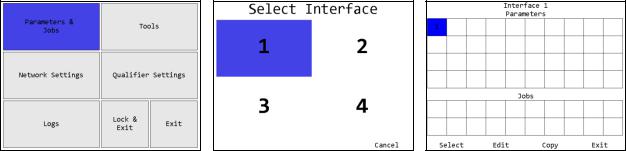
Parameters
Selecting Parameters
Figure 17: Main Menu - Parameters |
Figure 18: Select Interface |
Figure 19: Choose Parameter screen |
Soft keys
1.Select – Select the currently highlighted parameter to run and return to the Run screen. Only available for selectable parameters.
2.Edit – Edit the currently highlighted parameter.
3.Copy – Selects the currently highlighted parameter to be copied to another location.
4.Exit [ESC] – Returns to the Main Menu screen.
The Choose Parameters and Jobs screen shows all the parameters and jobs for an interface. Only the parameters with tools assigned will show their numbers on the grid. A selectable parameter will have a black number. A defined, but not selectable, parameter will be shown in red. A parameter is defined when a tool number is assigned to it.
A defined parameter will become unselectable in a few circumstances:
The assigned tool number is an empty tool slot, because either no tool was ever learned or the previous tool was forgotten
The assigned tool is assigned to another interface
The parameter configuration is invalid
Because parameters 1-16 are locked to tools 1-16 respectively, they will be blank if the associated tool slot is empty and yellow if the tool slot is occupied, but the tool is assigned to another interface.
EYFR04 User Manual |
23 of 76 |
v4.0 |
Chapter 3: Configuring the unit |
|
21 July 2017 |
 Loading...