


Assembly Qualifier
Qualificateur d'Assemblage
Calificador Incorporado
Operating Instructions
Instructions d’utilisation
Manual de instrucciones
Model No: EYFR02
IMPORTANT
This manual contains safety information. Read manual completely before first using this product and save this manual for future use.
IMPORTANT
Ce mode d’emploi contient des informations sur la sécurité. Lisez-le en entier avant d’utiliser le produit et conservez-le pour référence.
IMPORTANTE
Este manual contiene información de seguridad. Lea completamente este manual antes de utilizar por primera vez este producto, y guárdelo para poder consultarlo en el futuro.

Index |
|
|
|
|
|
|
|
|
|
English: |
Page |
3 |
|
Français: |
Page |
15 |
Español: |
Página |
27 |
FUNCTIONAL DESCRIPTION |
|
|
|
|
|||||
DESCRIPTION DES FONCTIONS |
|
|
|
|
|||||
DESCRIPCIÓN FUNCIONAL |
|
|
|
|
|
||||
|
|
|
(D) |
(E) |
(F) |
(G) |
|
|
|
(A) |
|
|
|
|
(J) |
|
|||
|
|
|
|
|
|
|
|||
|
|
|
|
|
|
|
|
(K) |
|
|
|
|
|
|
|
|
|
(L) |
|
(B) |
|
|
|
|
|
|
|
|
|
|
(C) |
|
(I) |
|
(H) |
|
|
(M) |
|
|
|
|
|
|
|
|
|
||
|
|
|
|
|
|
|
(N) |
|
|
|
|
|
|
|
|
|
(O) |
|
|
(A) |
I/O connector |
Connecteur d'entrée/sortie |
Conector de entrada/salida |
|
|
|
|
(B) |
Beeper |
Ronfleur |
Alarma |
|
|
|
|
(C) |
Volume switch |
Interrupteur de volume |
Interruptor de volumen |
|
|
|
|
(D) |
Fastening accept indicator |
Témoin d'acceptation de fixation |
Indicador de aceptación de sujeción |
|
|
|
|
(E) |
Antenna cover |
Cache d'antenne |
Cubierta de antena |
|
|
|
|
(F) |
Fastening reject indicator |
Témoin de rejet de fixation |
Indicador de rechazo de sujeción |
|
|
|
|
(G) |
Mounting holes |
Trous de montage |
Orificios de instalación |
|
|
|
|
(H) |
Signal strength indicator |
Témoin de puissance de signal |
Indicador de fuerza de señal |
|
|
|
|
(I) |
Power indicator |
Témoin d'alimentation |
Indicador de energía |
|
|
|
|
(J) |
Key lock |
Verrou à clé |
Bloqueador de llave |
|
|
|
|
(K) |
D-sub 9-pin female inch thread |
Filet de pouce femelle à |
Roscado hembra D-sub de |
9 broches D-sub |
9 clavijas |
||
(L) |
Power switch |
Interrupteur d'alimentation |
Interruptor de energía |
|
|
|
|
(M) |
Power plug inlet |
Entrée de fiche d'alimentation |
Entrada de corriente eléctrica |
|
|
|
|
(N) |
Soft key |
Clé d'enregistrement |
Tecla suave |
|
|
|
|
(O) |
Power cord |
Cordon d'alimentation |
Cable de energía |
|
|
|
|
- -

I.INTRODUCTION
Thank you for purchasing the Panasonic Assembly Qualifier. The AQ Wireless can monitor battery tools. In its simplest form, the AQ Wireless is configured to monitor a tool while it's running, determine if the fastening process was successful, report the status of the fastening.
How to Use This Manual
•Please read this manual completely before starting to use your AQ Wireless. If this unit is mishandled a fatal accident, bodily injury, or damage to the AQ Wireless may occur.
•This manual is intended to be a general guide to the operations of the AQ Wireless. If any additional questions or concerns arise, please contact a Panasonic Electric Works Power Tools representative.
•Please keep this manual for future reference. It contains important safety information that you must follow to use the AQ Wireless safety.
 WARNING!
•Do not disassemble the unit for repair or modifications. There is a high electrical voltage inside the unit that could cause electric shock.
•Do not allow any type of liquid to come into contact with any part of the unit.
•Immediately discontinue use of the unit if smoke, an abnormal odor, or an unusual sound is detected coming from the unit.
•Insert all fittings fully into their mating receptacles. Failure to do so could result in injury.
•Do not fold, bend or apply excessive force to any cable or fitting.
 CAUTION!
•This unit accepts an AC input voltage from 90VAC to 264VAC. Trying to operate this unit with a voltage outside that range may cause damage to the unit.
•Reception reliability may vary with site conditions. Be sure to verify proper Assembly Qualifier operation, including data reception, before starting work. Panasonic is not responsible for any damage sustained as a result of reception problems.
•Avoid placing or storing this unit in a location where it may become wet or dust covered.
•Do not place or mount this unit in an unstable area.
Dropping this unit may result in personal injury or damage to the unit.
•Before performing any maintenance on the unit, make sure to turn it off and remove the power plugs.
•There are no user serviceable parts inside the main enclosure of the unit.
•Proper operation is not guaranteed in the event that the Assembly Qualifier has been modified in any way.
•Always use this Assembly Qualifier with a Panasonic tool. Proper operation is not guaranteed when used with non-Panasonic tools.
Always turn the Assembly Qualifier’s power off when not in use.
•The socket-outlet shall be installed near the equipment and shall be easily accessible.
--
II. BEFOREUSINGTHEASSEMBLYQUALIFIER
Downloading software
The Assembly Qualifier is configured (relay output time, frequency, etc.) by connecting it to a computer. The Device Programmer application is required in order to do this. If you need to configure the Assembly Qualifier, the software can be downloaded from the following URL: http://denko.panasonic.biz/Ebox/powertool/factory/download/ENG/
Device Programmer system requirements
Read before use
•You may not be able to use the Device Programmer on some computers, even if they satisfy the system requirements.
•Depending on the computer being used, actual operation and screen content may differ from the information presented in this manual.
•The information in this manual is subject to change without notice.
•Unauthorized copying or other reproduction of this manual, in whole or in part, is prohibited.
•This portion of this manual describing Windows operation uses procedures and screens for Windows XP.
The Device Programmer application is not compatible with Macintosh computers. See below for supported operating systems.All illustrations in this manual are provided for reference purposes only.
Device Programmer system requirements
Supported computers |
|
Windows® 7: |
IBM® PC/AT compatible computer with Intel® Pentium® III |
|
1 GHz or faster CPU (including compatible CPUs) |
Windows Vista®: |
IBM® PC/AT compatible computer with Intel® Pentium® III |
|
800 MHz or faster CPU (including compatible CPUs) |
Windows® XP: |
IBM® PC/AT compatible computer with Intel® Pentium® III |
|
500 MHz or faster CPU (including compatible CPUs) |
Supported operating systems |
|
|
Pre-installed Japanese language version |
|
|
Microsoft® Windows® 7 |
(32-bit) |
Starter |
Microsoft® Windows® 7 |
(32-bit/64-bit) |
Home Basic/Home Premium/Professional/ |
|
|
Ultimate |
Microsoft® Windows Vista® (32-bit) |
Home Basic/Home Premium/Business/ |
|
|
|
Ultimate SP1/SP2 |
Microsoft® Windows® XP (32-bit) |
Home Edition/Professional SP2/SP3 |
|
Memory
Windows® 7: At least 1 GB (32-bit) or 2 GB (64-bit)
Windows Vista®/Windows® XP: At least 256 MB
--
Hard disk
Ultra DMA-100 or better
At least 10 MB of space for installing the software
•When recording to disk, space equal to at least twice the size of the data being created is required.
•An error may occur during recording if the compression setting is enabled.
Deselect the “Compress contents to save disk space” checkbox in the hard disk’s “Properties.”
Interface
Serial communications port (COM)
Other
Mouse or equivalent pointing device
Required software
.NET framework 3.5 SP1
•The software is not guaranteed to operate properly on all computers that satisfy the system requirements.
•The software does not support Windows® 3.1, Windows® 95, Windows® 98, Windows® 98SE, Windows® Me, Windows NT®, or Windows® 2000.
•The software is not guaranteed to operate properly on Windows® XP Media Center Edition, Tablet PC Edition, Windows Vista® Enterprise or Windows® 7 Enterprise.
•The software is not guaranteed to operate properly on 64-bit versions of Windows® XP or Windows Vista®.
•The software is not guaranteed to operate properly in Windows® 7 XP mode.
•The software is not guaranteed to operate properly on upgraded operating systems.
•Multi-boot systems are not supported.
•Multi-monitor systems are not supported.
•Only users with system administrator privileges can install or uninstall the software.
•Log in on an administrator account or standard user account before using the software. The software cannot be used by guest account usernames.
•The software is not guaranteed to operate properly on systems where the language has been changed using the Windows Vista®/Windows® 7 Ultimate multi-language user interface (MUI) function.
--

•Microsoft and Windows are registered trademarks or trademarks of Microsoft Corporation in the United States and other countries.
•IBM and PC/AT are registered trademarks of International Business Machines Corporation.
•Apple, the Apple logo, Macintosh, and MacOS are registered trademarks of Apple Inc.
•Intel, Pentium, and Celeron are registered trademarks or trademarks of Intel Corporation in the United States and other countries.
•Screenshots have been used in accordance with Microsoft Corporation guidelines.
•Other model names, company names, and product names are the trademarks or registered trademarks of their respective companies.
--

Installing the software
●Before installing the software, quit all other open applications.
1.Double-click “Panasonic Device Programmer.zip.”
2.Double-click “exe file”, then follow the instructions on the screen to install the software.
●Restart the computer once the installation is complete.
Disclaimer
Be sure to read before use.
Limitations:
The Device Programmer software is designed to be used to configure EYFR02 (Assembly Qualifier) settings.
Caution:
The following precautionary information applies to use of this software: Use of the software signifies your acceptance of the following terms of use.
Terms of Use:
•Panasonic makes no guarantee concerning the operation of this software.
•Panasonic is not liable for any direct, indirect, secondary, consequential, or special damage arising from the use or operation of this software, either by extension or effect.
•It is prohibited to reproduce or distribute this software.
Configuring settings with the software
1.Connect the Assembly Qualifier to the computer.
• Use an RS-232C straight cable.
Using a serial RS-232C port to connect the Assembly Qualifier
Using a USB port to connect the Assembly Qualifier
|
RS-232C |
USB serial conversion |
RS-232C straight cable |
straight cable |
|
|
|
adapter |
2.Turn on the Assembly Qualifier.
3.Launch the Device Programmer application.
4.Click the “Read Settings” button.
•The software will load the Assembly Qualifier’s current settings.
--

5.Configure the settings as desired.
• Enter values and select settings.
|
|
|
Function description |
Initial |
|
|
|
setting |
|
|
|
|
|
|
|
|
(A) |
Time during which to invalidate the next |
0 (0 sec) |
|
|
reception (so that cycles are not counted |
||
(A) |
|
|
twice) |
|
|
(B) |
Fastening accept signal relay output time* |
20 |
|
|
|
|||
(B) |
|
(0.2 sec) |
||
|
|
|
||
(C) |
|
(C) |
Fastening reject signal relay output time* |
20 |
|
(0.2 sec) |
|||
|
(D) |
|||
|
|
Sets the beep mode to any of three options. |
|
|
|
(E) |
(D) |
1Accept and Reject: Fastening accept |
Accept and |
|
(F) |
and fastening reject |
Reject |
|
|
|
2Accept only: Fastening accept only |
||
|
|
|
|
|
(G) |
|
|
3 Reject only: Fastening reject only |
|
|
|
|
Sets the relay output method to either of |
|
|
|
(E) |
two options. |
Momentary |
|
|
1 Latching: Output continuously. |
||
|
|
|
2 Momentary: Output for duration |
|
|
|
|
defined by relay output time. |
|
|
|
(F) |
Sets the frequency to any of 12 channels. |
1 |
|
|
(G) |
Displays the registered tool ID. |
0000 |
*Valid only when (E) has been set to 2 (“Momentary”). Setting a long relay output time slows the reception process.
• File menu
1 Creates a new file.
2 Opens a previously created file.
3 Saves the current settings.
4 Saves the current settings as a new file.
5 Opens recently used files.
6 Exits the Device Programmer application.
• Product menu
1 Selects the Assembly Qualifier.
(This setting does not need to be changed.) 2 Not used
--
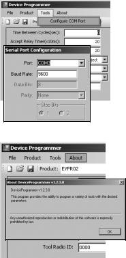
• Tools menu
Configures the port used to connect the Assembly Qualifier to the computer.
1 Selects the port.
2 Sets the baud rate. Initial setting: 9600
• About menu
Allows you to check the software’s version.
Installing the Assembly Qualifier
Installation method
Mount the Assembly Qualifier securely with screws using the four mounting holes.
NOTE
Before mounting the Assembly Qualifier, test it where you plan to install it to ensure that there are no communications issues.
CAUTION
Verify that the Assembly Qualifier is not affected by other wireless equipment before mounting it.
--
III. OPERATION
Registering the tool with the Assembly Qualifier
●Preparing the Assembly Qualifier
1.Connect the power cord to the Assembly Qualifier.
2.Plug the power cord into a wall outlet.
3.Turn on the Assembly Qualifier.
All indicators will turn on and off, leaving only the power indicator on.
4.Insert a soft key into the key lock and turn to the left.
The power indicator will flash, and the Assembly Qualifier will enter tool registration standby mode.
●Preparing the tool to be registered
1.Operate the tool so that all the panel lights are off (if any panel lights are on).
2.Pull the tool’s trigger.
Once the tool has been registered, the Assembly Qualifier’s fastening accept signal will turn on.
3.Turn the Assembly Qualifier’s soft key to the right.
The power indicator will turn on and the Assembly Qualifier will enter receive mode, completing the registration process.
CAUTION
The registration procedure should be performed away from other transmitterequipped tools. When registering multiple tools, do so one pair at a time. Failure to do so may cause an unintended tool to be registered with the Assembly Qualifier.
Indicators
Indicator |
|
State |
Fastening |
Green |
Fastening accept signal received. |
accept indicator |
Off |
No fastening accept signal is being received. |
Fastening |
Red |
Fastening reject signal received. |
reject indicator |
Off |
No fastening reject signal is being received. |
|
Blue |
Power on (receive mode) |
Power indicator |
Off |
Power off |
|
Flashing blue |
Tool registration standby mode |
|
Yellow |
Strong signal |
|
Orange |
Medium-strength signal |
Signal strength |
Red |
Weak signal |
indicator |
Flashing red |
Signal received during double-count prevention |
|
time. |
|
|
|
|
|
Off |
No fastening signal is being received. |
- 10 -
Setting the beep volume
Set the beep volume with the volume switch.
Low volume |
OFF |
High volume |
(Approx. 75 dB) |
|
(Approx. 90 dB) |
NOTE
The beep mode setting is configured while the Assembly Qualifier is connected to a computer. See page 7.
Using the software
1.Turn on the Assembly Qualifier’s power switch.
All indicators will turn on and off, leaving only the power indicator on.
2.Use the registered tool to perform fastening work.
Status of tool’s fastening |
Assembly Qualifier |
confirmation indicator |
indicators |
|
|
Green |
Fastening accept indicator |
|
|
Red |
Fastening reject indicator |
|
|
Finishing work
Turn off the Assembly Qualifier’s power switch.
I/O connector
1 |
2 |
|
Pin no. |
Description |
Rating |
|
|
1 |
Reset input pin (input) |
Input rating: 24 V/60 mA |
|||
|
|
3 |
2 |
Reset input pin (common) |
— |
|
5 |
4 |
3 |
Relay output pin (common) |
— |
||
|
||||||
|
4 |
Relay output pin (fastening accept) |
Output rating: 30 VDC/5 A |
|||
|
|
|
5 |
Relay output pin (fastening reject) |
Output rating: 30 VDC/5 A |
- 11 -

5-pin connector schematic and pin out
1 2
3
5 4
Relay
ACCEPT RELAY
INTERNAL CONTROL
Relay
REJECT RELAY
INTERNAL CONTROL
RESET INPUT |
1 |
|
|
RESET COMMON |
2 |
|
|
RELAY COMMON |
3 |
|
|
ACCEPT RELAY |
4 |
|
|
REJECT RELAY |
5 |
To connect to the 5-pin connector, you will need:
A commercially available round connector (manufacturer: Amphenol ; model no.: T3360 001)
- 12 -
 Loading...