


Operating Instructions/Bedienungsanleitung/ Mode d’emploi/Istruzioni per l’uso/ Instrucciones de funcionamiento/
Camera Adapter/Kameraadapter/ Adaptateur de Camera/Adattatore della telecamera/ Adaptador de videocámara/
Model No. AG-CA300G
SDI |
IN |
|
|
GENLOCK |
|
OUT |
|
RETOUT |
|
 CALL
CALL
RET |
|
|
RET |
IN |
BS |
CTRL |
|
OUT |
REMOTE
Before operating this product, please read the instructions carefully and save this manual for future use.
Bitte lesen Sie vor Inbetriebnahme dieses Produkts die Anleitungen sorgfältig durch und bewahren Sie dieses Handbuch für spätere Verwendung auf.
Avant de vous servir de ce produit, veuillez lire attentivement les instructions et enregistrer ce manuel pour une utilisation ultérieure.
Prima di utilizzare questo prodotto, leggere attentamente le istruzioni di questo manuale e conservarlo per riferimento futuro.
Antes de poner este producto en funcionamiento, lea atentamente las instrucciones y conserve este manual para uso futuro.
“ ”
_
■ 2 5
ESPAÑOL ITALIANO FRANÇAIS DEUTSCH ENGLISH
F0909T0 -F @ |
|
Printed in Japan |
VQT2H44 |

Read this first !
For General
WARNING:
yTo reduce the risk of fire or electric shock, do not expose this equipment to rain or moisture.
yTo reduce the risk of fire or electric shock, keep this equipment away from all liquids. Use and store only in locations which are not exposed to the risk of dripping or splashing liquids, and do not place any liquid containers on top of the equipment.
WARNING:
Always keep accessories (ferrite core) out of the reach of babies and small children.
CAUTION:
In order to maintain adequate ventilation, do not install or place this unit in a bookcase, built-in cabinet or any other confined space. To prevent risk of electric shock or fire hazard due to overheating, ensure that curtains and any other materials do not obstruct the ventilation.
CAUTION:
To reduce the risk of fire or electric shock and annoying interference, use the recommended accessories only.
CAUTION:
Excessive sound pressure from earphones and headphones cause can hearing loss.
CAUTION:
Do not remove panel covers by unscrewing them.
To reduce the risk of electric shock, do not remove the covers. No user serviceable parts inside.
Refer servicing to qualified service personnel.
indicates safety information.
The rating plate is on the underside of the unit.
EEE Yönetmeliğine Uygundur.
EEE Complies with Directive of Turkey.
E-1

Read this first ! (continued)
EMC NOTICE FOR THE PURCHASER/USER OF THE APPARATUS
1. |
Applicable standards and operating environment (For Europe) |
ENGLISH |
|
The apparatus is compliant with: |
|
|
|
|
|
z standards EN55103-1 and EN55103-2 1996.11, and |
|
|
z electromagnetic environments E1, E2, E3, and E4. |
|
2. |
Pre-requisite conditions to achieving compliance with the above standards |
|
|
<1> Peripheral equipment to be connected to the apparatus and special connecting cables
zThe purchaser/user is urged to use only equipment which has been recommended by us as peripheral equipment to be connected to the apparatus.
zThe purchaser/user is urged to use only the connecting cables described below.
<2> For the connecting cables, use shielded cables which suit the intended purpose of the apparatus.
zVideo signal connecting cables
Use double shielded coaxial cables, which are designed for 75-ohm type high-frequency applications, for SDI (Serial Digital Interface).
Coaxial cables, which are designed for 75-ohm type high-frequency applications, are recommended for analog video signals.
zAudio signal connecting cables
If your apparatus supports AES/EBU serial digital audio signals, use cables designed for AES/EBU. Use shielded cables, which provide quality performance for high-frequency transmission applications, for analog audio signals.
zOther connecting cables (IEEE1394, USB)
Use shielded cables, which provide quality performance for high-frequency applications, as connecting cables.
zWhen connecting to the DVI signal terminal, use a cable with a ferrite core.
zIf your apparatus is supplied with ferrite core(s), they must be attached on cable(s) following instructions in this manual.
3.Performance level
The performance level of the apparatus is equivalent to or better than the performance level required by these standards.
However, the apparatus may be adversely affected by interference if it is being used in an EMC environment, such as an area where strong electromagnetic fields are generated (by the presence of signal transmission towers, cellular phones, etc.). In order to minimize the adverse effects of the interference on the apparatus in cases like this, it is recommended that the following steps be taken with the apparatus being affected and with its operating environment:
1.Place the apparatus at a distance from the source of the interference.
2.Change the direction of the apparatus.
3.Change the connection method used for the apparatus.
4.Connect the apparatus to another power outlet where the power is not shared by any other appliances.
E-2

Read this first ! (continued)
For U.S.A. and Canada
IMPORTANT SAFETY INSTRUCTIONS
1)Read these instructions.
2)Keep these instructions.
3)Heed all warnings.
4)Follow all instructions.
5)Do not use this apparatus near water.
6)Clean only with dry cloth.
7)Do not block any ventilation openings. Install in accordance with the manufacturer’s instructions.
8)Do not install near any heat sources such as radiators, heat registers, stoves, or other apparatus (including amplifiers) that produce heat.
9)Do not defeat the safety purpose of the polarized or grounding-type plug. A polarized plug has two blades with one wider than the other. A grounding-type plug has two blades and a third grounding prong. The wide blade or the third prong are provided for your safety. If the provided plug does not fit into your outlet, consult an electrician for replacement of the obsolete outlet.
10)Protect the power cord from being walked on or pinched particularly at plugs, convenience receptacles, and the point where they exit from the apparatus.
11)Only use attachments/accessories specified by the manufacturer.
12)Use only with the cart, stand, tripod, bracket, or the table specified by the manufacturer, or sold with the apparatus. When a cart is used, use caution when moving the cart/apparatus combination to avoid injury from tip-over.
13) Unplug this apparatus during lightning storms or when unused for long periods of
time. |
S3125A |
|
14)Refer all servicing to qualified service personnel. Servicing is required when the apparatus has been damaged in any way, such as power-supply cord or plug is damaged, liquid has been spilled or objects have fallen into the apparatus, the apparatus has been exposed to rain or moisture, does not operate normally, or has been dropped.
E-3

Read this first ! (continued)
For U.S.A. and Canada
FCC Note:
This equipment has been tested and found to comply with the limits for a class B digital device, pursuant to Part 15 of the FCC Rules. These limits are designed to provide reasonable protection against harmful interference in a residential installation. This equipment generates, uses, and can radiate radio frequency energy and, if not installed and used in accordance with the instruction manual, may cause harmful interference to radio communications. However, there is no guarantee that interference will not occur in a particular installation. If this equipment does cause harmful interference to radio or television reception, which can be determined by turning the equipment off and on, the user is encouraged to try to correct the interference by one or more of the following measures:
zReorient or relocate the receiving antenna.
zIncrease the separation between the equipment and receiver.
zConnect the equipment into an outlet on a circuit different from that to which the receiver is connected.
zConsult the dealer or an experienced radio/TV technician for help.
The user may find the booklet “Something About Interference” available from FCC local regional offices helpful.
Warning :
To assure continued FCC emission limit compliance, follow the attached installation instructions and the user must use only shielded interface cables when connecting to peripheral devices. Also any unauthorized changes or modifications to this equipment could void the userís authority to operate this device.
A rechargeable battery that is recyclable powers the product you have purchased.
ENGLISH
E-4

Contents
Read this first ! ............................................................................................. |
E-1 |
Supplied Accessories .................................................................................. |
E-6 |
Features ........................................................................................................ |
E-6 |
System Configuration Diagram................................................................... |
E-7 |
Precautions When Connecting the System ............................................... |
E-8 |
Setting up the camera recorder .................................................................. |
E-9 |
Part Names and Functions .......................................................................... |
E-10 |
About the RET Signal................................................................................... |
E-13 |
Mounting to the Camera Recorder ............................................................. |
E-14 |
Fixing the Connector Cover ........................................................................ |
E-15 |
Fixing the Cables.......................................................................................... |
E-16 |
Mounting of the Battery Plate ..................................................................... |
E-17 |
Mounting and Connection of the BT-LH80W/WU ...................................... |
E-19 |
BT-LH80W/WU GPI Setting .......................................................................... |
E-20 |
Connector Signals........................................................................................ |
E-21 |
About the Power Supply Cable ................................................................... |
E-23 |
About the RET CTRL connector ................................................................. |
E-24 |
Specifications ............................................................................................... |
E-25 |
E-5

Supplied Accessories
VF cable a 1 |
Cable strap a 2 |
Ferrite core a 1 |
ENGLISH
REMOTE cable a 1 |
Battery plate a 1 |
Features
This unit has the following features:
zThis unit is connected with the base station (AG-BS300P/E; optional) with a power supply cable (refer to page 23 for specification) and 2 BNC cables, and it supplies the power to the camera recorder while transferring the video and audio signals being recorded with the camera recorder.
zSince the signal between the unit and the base station is transmitted as an uncompressed digital signal, it is possible to transmit the video and audio signal being recorded on the camera recorder without any degradation.
zIt is possible to extend the distance between the unit and the base station up to 100 m. (When using 5C-FW BNC cable)
zIt is possible to transfer one line of the return video (RET). (2 lines of transfer are possible depending on the mode.)
zIt is possible to transfer one line of the intercom (INCOM).
zIt is possible to operate with DC.
zThe unit is compatible with multi-format.
E-6

System Configuration Diagram
|
|
RET OUT |
|
|
|
|
|
|
|
|
Monitor |
|
|
|
|
|
|
|
|
|
SDI OUT ° 2 |
|
|
|
|
|
|
|
|
|
|
VIDEO OUT |
|
VF/return |
|
|
|
|
|
|
|
(Composite |
|
|
|
|
|
|
|
|
|
signal) |
||
|
video |
VF OUT |
|
|
|
|
|
CA |
|
|
|
|
|
|
|
BS IN |
|
|
Intercom |
||
|
|
|
|
|
|
|
OUT |
|
||
BT-LH80W/WU |
Dedicated cable |
|
|
|
|
|
|
tally |
||
|
|
|
|
|
|
|||||
|
(monitor video, |
|
|
|
BS |
|
|
|
|
|
|
GPI) |
|
|
|
|
OUT |
|
CA IN |
|
Return (SDI) |
|
|
|
|
|
|
|
|
|
||
|
|
|
|
|
|
|
|
|
|
|
|
|
REMOTE |
|
|
|
BNC ° 2 |
|
|
Return |
|
|
|
|
|
|
Use 5C-FW |
|
|
|||
|
|
|
|
|
(Maximum |
|
|
(Composite |
||
|
RC cable (control, |
|
|
|
|
|
||||
|
|
|
|
extension |
|
|
signal) |
|||
|
monitor video) |
|
|
|
|
|
||||
|
|
|
|
length: 100 m) |
|
|
||||
|
|
|
|
|
SDI IN |
|
GENLOCK |
|||
|
|
|
CALL |
|
RETOUT |
|
|
|
|
|
|
|
|
|
|
GENLOCK |
|
|
|
|
|
|
|
|
|
|
OUT |
|
|
|
|
|
|
|
|
RET |
|
|
|
|
|
|
|
|
|
|
RET |
IN |
BS |
DC IN |
DC OUT |
|
|
|
REMOTE |
|
|
CTRL |
|
|
|
||||
|
|
|
|
REMOTE |
|
|
||||
|
|
|
|
|
24 V |
|
24 V |
AG-BS300P/E |
|
|
|
|
|
AG-CA300G |
|
GENLOCK |
|||||
|
|
|
|
|
|
|||||
|
SDI |
SDI |
|
|
|
LOOPOUT |
||||
|
|
|
|
Power supply |
|
|||||
|
OUT2 |
IN |
|
|
|
|
|
|||
|
|
|
|
|
|
cable |
(Refer to |
|
|
|
AG-HPX300/ |
Main line SDI |
|
|
|
page 23) |
|
|
AC IN |
||
video (BNC) |
|
|
|
Resistance: |
|
|
||||
301/302/304 |
|
|
|
|
|
|||||
Use the 3C-FW |
|
|
|
Use 0.5 Ω or |
|
|
||||
GENLOCK IN |
|
|
|
|
|
|||||
|
|
|
|
|
less |
|
|
|
DC IN |
|
|
|
|
|
|
|
(Maximum |
|
|
|
|
|
|
GENLOCK |
|
|
|
extension |
|
|
|
|
|
|
OUT |
|
|
|
length: 100 m) |
|
|
||
|
|
|
|
|
|
|
|
|
|
|
GENLOCK (BNC) |
|
|
|
|
|
|
|
|
||
Recommended to |
|
|
|
|
|
|
|
|
||
use the 3C-FW |
|
|
|
|
|
|
|
|
||
|
|
Anton/Bauer |
|
|
|
|
|
AG-EC4G |
|
|
|
|
Hytron, |
|
|
|
|
|
|
|
|
|
|
Trimpac |
|
|
|
|
|
|
AJ-RC10G |
|
|
|
|
|
IDX A-AB2E |
IDX |
|
|
|||
|
|
|
|
ENDURA7/10 |
|
|||||
|
|
|
|
|
|
|
|
|||
<Notes> |
|
|
|
|
|
|
|
|
|
|
z Be sure to connect cables 1 - 6 shown above. |
|
|
|
|
|
|||||
z Other compatible camera: AJ-HPX3700G, AJ-HPX3000G, AJ-HPX2700G, AJ-HPX2000/2100, |
||||||||||
|
|
AG-HPX500/502, AJ-HDX900P/E |
|
|
|
|||||
E-7

Precautions When Connecting the System
Be aware of the following points when connecting the camera recorder and the base station to the unit.
zMaximum power supply from this unit to the camera recorder is 5 A. Be careful that the total power consumption does not exceed 5 A when the camera recorder and LCD monitor or any other equipment are used simultaneously.
zUse the dedicated power supply cable when connecting with the base station. (Refer to page 23) Make sure the power is switched OFF when connecting or disconnecting the power supply cable.
zUse 5C-FW as the BNC cable connecting this unit with the base station. Maximum extension length of 100 m cannot be achieved if any other cable is used.
zVideo on the viewfinder (LCD monitor) may be interrupted momentarily when the RET signal selection switch of the unit is pressed to confirm the RET signal.
zOnly a dynamic microphone can be used as the microphone for the INCOM.
zMost of the operational functions of the camera recorder will be controlled by the remote control unit (AG-EC4G; optional, or AJ-RC10G; optional) when the remote control unit is connected to this unit, and the remote control unit is enabled by turning the power on. (However, POWER ON/OFF, AWB/ABB, MODE CHECK, REC START/STOP, FF and REW can also be operated from the camera recorder.)
zEven if the remote control unit is connected to the base station, operation by the camera recorder becomes enabled when the remote control unit is turned OFF.
zWhen the SDI output of the camera recorder is set to 720P, 720P 3-value SYNC signal is output from the GENLOCK OUT connector of this unit even if 2-value SYNC signal is input to the REF input of the base station. A/B field of the VBS output from the camera recorder and the A/B field of the REF input into the base station cannot be matched.
However, this is not the case when the SDI output of the camera recorder is SD.
zWhen connecting the unit with the camera recorder, connect the REMOTE connector of the camera recorder with the REMOTE connector of the unit using the included remote control cable.
Power of this unit can be turned on/off simultaneously with the power switch of the camera recorder. This unit will not be powered on unless the remote control cable is connected.
zWhen the video format is changed in the camera recorder, turn the power of this unit and the base station OFF once, and turn it back on.
zThere is only one line of video signal sent from the unit to the base station. The viewfinder video from the camera recorder cannot be viewed from the VIDEO OUT connector and the SDI OUT connector of the base station.
zDo not supply power to the DC IN 24 V connector of this unit except from the base station.
zThis unit cannot be used with camera recorders with an SDI IN option.
Make changes so the GENLOCK IN becomes possible either by removing the SDI IN option, or set the REC SIGNAL in the menu setting to something other than SDI.
zUse coaxial cable of less than 50 cm when connecting the SDI IN connector (BNC) to the SDI output from the camera recorder
ENGLISH
E-8

Precautions When Connecting the System (continued)
zMake sure to connect the GENLOCK OUT connector of this unit and the GENLOCK IN connector of the camera recorder using a BNC cable, and set the GENLOCK menu of the camera recorder to “EXT”.*
(However, this setting will be automatically performed on the AG-HPX300/301/302/304 and the AG-HPX500/502, so it is not required to perform this setting)
Also, if the camera recorder is being used in HD mode, set the "GL PHASE" in the GENLOCK menu to “HD SDI”.*
Connect the cables as shown in 1 - 6 on page 7.
*For the setting method, refer to the operating instructions of the camera recorder.
zDo not perform version update of the camera recorder while this unit and the camera adapter are connected. Perform the version update of the camera recorder with the camera recorder on its own.
zWhen connecting this unit with the camera recorder, match the system format of the camera recorder with the video format of the SDI signal.
zIn systems combining this unit and the AG-HPX500/502, the AG-HPX500/502 should not be used in playback mode or IEEE1394 mode.
zWhen connecting this unit with the AJ-HDX900P/E, set the OUTPUT SEL switch on the camera recorder so the HD SDI signal is output from the VIDEO OUT connector of the camera recorder.
Setting up the camera recorder
Setup the camera recorder to configure a system by connecting this unit with the AG-BS300P/E and the camera recorder.
For the setting of the camera recorder, refer to the operating instructions of the camera recorder.
Setting of the video format
Using camera recorder menu operations or switch operations, set the video signal format of the output from the SDI output connector of the camera recorder and the video signal format for recording to the same format.
Setting of the CRT VF
Set the VF TYPE to be used on the camera recorder using the menu operation of the camera recorder.
If it is set to VF TYPE: SD, only the SD video can be checked for the return video (RET video) from this unit.
Setting of the GENLOCK MODE
Set the GENLOCK MODE of the camera recorder to GENLOCK: EXT using the menu operation of the camera recorder.
(This setting is not necessary for AG-HPX300/ 301/302/304 and AG-HPX500/502.)
Setting of the GENLOCK PHASE
Set the GL PHASE of the camera recorder to GL PHASE: HD SDI using the menu operation of the camera recorder.
If it is used connected to the AG-HPX500/502, set the GL SELECT item to SDI, and the GL PHASE item to OFF.
Setting of the battery
Power is supplied from the base station to the camera recorder from the battery connector of the camera recorder via this unit. When the power is supplied from the base station connecting this unit and the camera recorder, set the battery setting of the camera recorder to "TYPE B", the voltage to display as FULL to "13.0 V", near-end voltage to "12.5 V", and end voltage to "12.0 V" when the power is supplied to the camera recorder. For details, refer to the operating instructions of the camera recorder.
E-9
Part Names and Functions
11
3 |
2 |
1 |
INCOM |
|
|
VF OUT |
|
|
|
|
|
|
|||
|
|
10 |
CALL |
|
|
|
|
|
|
9 |
|
|
|
|
|
|
|
RET |
|
BS |
|
|
|
|
|
8 |
RET |
IN |
OUT |
REMOTE |
|
|
|
|
|
|
|||
|
|
CTRL |
|
|
|
|
|
|
|
|
7 |
6 |
5 |
4 |
12 |
1. DC IN 24 V connector |
|
3. Intercom connector |
|
||||
This is the power supply connector for the unit.
This is a DC 24 V supply connector from the base station to the unit.
2.VF OUT connector
This is the connector to the LCD monitor (BT-LH80W/WU; optional) and AG-YA500G (optional).
The output is switched between the return signal from the base station and the video signal being recorded with the camera recorder.
Connect with the LCD monitor using the included dedicated cable.
Refer to the operating instruction of the AG-YA500G when the AG-YA500G is used. For details of signals for the VF OUT connector, refer to [About the RET Signal] (page 13).
<Note>
When the base station is connected to the remote control unit and the AJ-HDX900P/E, video for the recording is not output when the remote control unit is turned off.
Connect the headset for the intercom. Only a dynamic microphone can be used.
The length of the cable to be used should be 3 meters or shorter.
4.REMOTE connector
This is a connector to transmit/receive the control signal between the base station and the camera recorder.
Connect with the REMOTE connector of the camera recorder using the included REMOTE cable.
Camera recorder is controlled using the remote control unit connected to the base station.
<Note>
Power of the unit will not turn on unless it is connected to the REMOTE connector of the camera recorder with included remote cable.
5.BS OUT connector
This is a connector that supplies the signal to the base station.
Connect with the CA IN connector of the base station using the BNC cable (5C-FW).
ENGLISH
E-10

Part Names and Functions (continued)
6.BS IN connector
This is a connector receiving the signal from the base station.
Connect with the CA OUT connector of the base station using the BNC cable (5C-FW).
7.RET CTRL connector
This is a connector to be used when the video signal output from the 2. VF OUT connector is to be switched with the external RET switch box. For the pin assignment, refer to [About the RET CTRL connector] (page 24).
8.RET signal selection switch
This is a switch that selects the video signal output from the 2. VF OUT connector from either the return signal (RET signal) from the base station or the video signal recording on the camera recorder.
It will switch to the return signal while the switch is pushed.
<Note>
Video may be disrupted when the signal is switched.
9.TALLY lamp
This will light up while the TALLY signal is input to the unit from the base station.
It will also light up while the CALL switch on the front panel of the base station is pressed. However, there is no change when the CALL switch on the base station is pressed while this is lit with the TALLY signal input to the unit.
10.CALL switch
TALLY lamp on the base station is lit while this switch is pressed.
However, while the TALLY signal is input to the base station, there will be no change when the CALL switch is pressed on this unit.
11.BATTERY IN connector
This is a connector used to connect a battery to the unit.
It is possible to operate the unit with a battery by connecting the battery.
However, power supplied from the 1. DC IN 24 V connector will have priority if there is power supplied from the 1. DC IN 24 V connector.
When using a battery, mount the included battery plate to the rear panel of this unit. For the mounting method, refer to [Mounting of the Battery Plate] (page 17).
12.DC IN 24 V connector cover
Mount this cover on the 1. DC IN 24 V connector when the power supply cable is not connected to the 1. DC IN 24 V connector.
E-11

Part Names and Functions (continued)
|
|
MIC |
|
|
ON |
|
|
OFF |
|
SDI IN |
PTT |
13 |
INCOM |
|
|
|
|
14 |
GENLOCK |
LEVEL |
OUT |
17 |
|
|
||
|
RET OUT |
|
15 |
|
|
|
|
16
18
19
ENGLISH
13.SDI IN connector
This inputs the SDI signal output from the camera recorder.
14.GENLOCK OUT connector
This is a reference signal output connector for locking the camera recorder with the base station.
Connect with the GENLOCK IN connector of the camera recorder with the BNC cable.
<Note>
When connecting the unit with the camera recorder, set the GENLOCK item to “EXT” in the GENLOCK menu of the camera recorder. However, it is not necessary to set this with the AG-HPX300/301/302/304 and the AG-HPX500/502.
Set the GL PHASE in the GENLOCK menu of the camera recorder to “HD SDI” when the camera recorder is operated in HD mode.
When connecting the unit with the AG-HPX500/502, set the GL SELECT item to “SDI” and the GL PHASE item to “OFF”. Also, when a camera recorder with SDI IN option is used, set the REC SIGNAL item to something other than “SDI” with the menu setting in the camera recorder, or remove the SDI IN option and make the GENLOCK IN possible.
15.RET OUT connector
This is an output connector of the return video signal from the base station.
The composite signal supplied to the RET IN VIDEO signal input connector of the base station is output when the camera recorder is operating in HD mode.
Return signal selected by the RET select switch of the base station is output when the camera recorder is operating in SD mode. For details about the RET signal, refer to [About the RET Signal] (page 13).
16.Cable clamper
This is a clamper for the power supply cable, VF OUT cable, and BNC cables.
17.DC OUT connector
This is a connector supplying power to the camera recorder itself.
18.MIC switch
This is an ON/OFF switch of the intercom microphone.
There are 3 positions: ON/OFF/PTT. (PTT: MIC is turned ON only while this is pressed.)
19.INCOM volume level potentiometer
This is a potentiometer to adjust the volume level of the intercom.
E-12

About the RET Signal
The RET signal input to the base station can be transferred to this unit.
When the video format of the camera recorder is HD format, both of the video signals supplied to the RET IN SDI connector and the RET IN VIDEO connector of the base station are transferred to this unit. When the video format of the camera recorder is SD format, either of the video signals supplied to the RET IN SDI connector or the RET IN VIDEO connector of the base station can be transferred to this unit. The signal output from the VF OUT connector (D-Sub connector) of this unit can be switched by the RET switching switch at the rear panel of the base station.
|
|
AG-BS300P/E |
|
AG-CA300G |
|
Video format of the |
Input signal |
|
RET signal |
VF OUT connector |
RET OUT |
camera recorder |
Input signal |
selection switch |
connector |
||
|
connector name |
|
at the rear |
(D-sub) |
(BNC) |
|
|
|
|
||
|
|
|
|
|
|
|
RET IN SDI |
HD SDl (signal A) |
|
HD component |
|
|
|
Composite |
SDI |
|
|
|
RET IN VIDEO |
(signal A) |
|
||
|
(signal B) |
|
|
||
|
|
|
|
|
|
|
RET IN SDI |
HD SDl (signal A) |
|
SD component |
|
|
|
Composite |
VIDEO |
|
|
|
RET IN VIDEO |
(signal B) |
|
||
|
(signal B) |
|
Composite |
||
HD |
|
|
|
||
RET IN SDI |
SD SDl (signal C)* |
|
|
(signal B) |
|
|
|
|
|||
|
RET IN VIDEO |
Composite |
SDI |
Signal is not output |
|
|
(signal B) |
|
|
|
|
|
|
|
|
|
|
|
RET IN SDI |
SD SDl (signal C)* |
|
SD component |
|
|
|
Composite |
VIDEO |
|
|
|
RET IN VIDEO |
(signal B) |
|
||
|
(signal B) |
|
|
||
|
|
|
|
|
|
|
RET IN SDI |
SD SDl (signal A) |
|
SD component |
Composite |
|
|
Composite |
SDI |
||
|
RET IN VIDEO |
(signal A) |
(signal A) |
||
|
(signal B) |
|
|||
|
|
|
|
|
|
|
RET IN SDI |
SD SDl (signal A) |
|
SD component |
|
|
|
Composite |
VIDEO |
|
|
|
RET IN VIDEO |
(signal B) |
|
||
|
(signal B) |
|
|
||
SD |
|
|
|
|
|
RET IN SDI |
HD SDl (signal C)* |
|
|
Composite |
|
|
|
|
|||
|
RET IN VIDEO |
Composite |
SDI |
Signal is not output |
|
|
(signal B) |
|
|
(signal B) |
|
|
|
|
|
|
|
|
RET IN SDI |
HD SDl (signal C)* |
|
SD component |
|
|
|
Composite |
VIDEO |
|
|
|
RET IN VIDEO |
(signal B) |
|
||
|
(signal B) |
|
|
||
|
|
|
|
|
|
* (signal C) shows that it is a signal which cannot be transferred.
E-13

Mounting to the Camera Recorder
Mount the unit to a camera recorder using the following procedure:
<Notes> |
|
|
|
z When connecting this unit to the camera recorder, set the GENLOCK in the GENLOCK menu of the |
ENGLISH |
||
camera recorder to "EXT". However, it is not necessary to set this with the AG-HPX300/301/302/304 |
|||
|
|||
and the AG-HPX500/502. |
|
|
|
z It may be required to update the version of the software for the camera recorder depending on the |
|
||
version used by the camera recorder. Consult the dealer. |
|
||
1 Align the guides at the back of the camera |
4 Connect one end of the power cable |
|
|
recorder with the guides of the unit, and push |
connected to the base station to the DC IN |
|
|
it in the direction of the arrow securely. |
24 V connector of the unit. |
|
|
|
5 Connect the REMOTE connector of the unit |
|
|
|
with the REMOTE connector of the camera |
|
|
|
recorder using the included REMOTE cable. |
|
|
3
2 Connect the GENLOCK OUT connector of this unit with the GENLOCK IN connector of the camera recorder using a BNC cable (commercially available) of 50 cm or shorter.
3 Mount the supplied ferrite core on the BNC |
5 |
2 |
cable within 15 cm from the SDI connector of |
|
|
the camera recorder. |
|
|
Connect the SDI IN connector of this unit with |
|
|
the SDI OUT connector of the camera |
|
|
recorder* using a BNC cable (commercially |
|
|
available; 3C-FW) of 50 cm or shorter. There |
|
|
are camera recorders that display VIDEO |
|
|
OUT, but make sure to set it to SDI signal by |
|
4 |
the menu settings or switch settings before |
|
|
connecting. |
|
|
*If the output connector of the camera recorder is set to SDI, any connector can be used.
E-14

Fixing the Connector Cover
Fix the connector cover as explained below when this unit is used with the power cables connected.
1 Fix the included cable strap onto the power supply cables.
2 After connecting the DC IN 24 V connector cover of this unit with the connector cover of the power supply cables, fix it to the connector of the power supply cables using the cable strap.
E-15

Fixing the Cables
Fix the cables connected to this unit as explained 2 below. If not fixed correctly, this unit may fall off
when excessive load is applied to the cable.
1 Run the power supply / VF / BS IN / BS OUT
cables through the cable clamper.
2 Fix the power supply / VF / BS IN / BS OUT cables to the handle of the camera recorder using the included cable strap.
1
ENGLISH
E-16

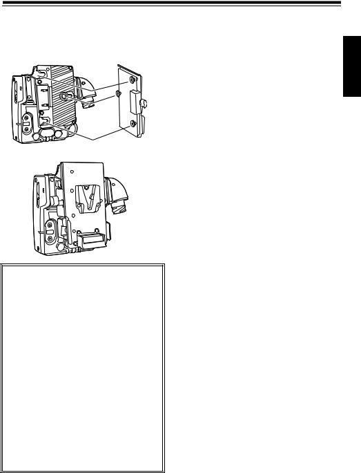
Mounting of the Battery Plate
When using a battery, mount the included battery plate to the rear panel of the unit.
1 Remove the 2 screws and remove the rear panel cover. Also remove the 4 screws from the main body.
<Note>
The battery may fall off if the screws are loose.
4 Cover for the rear panel removed in 1 can be mounted on the front panel so it will not get lost. Mount the cover for the rear panel removed in 1 as shown in the illustration using the 2 screws.
2 Connect the battery connector of the unit to the connector on the included battery plate.
3 Mount the battery plate securely using the 4 screws removed from the main body in 1, making sure there is no slack.
E-17
Mounting of the Battery Plate (continued)
When using a V-mount type battery pack
Mount the V-mount adapter plate (optional).
Fit the plate, sliding it in the manner shown in the illustration.
<Caution>
zDo not use any other screws except the screws removed from main unit in 1 to mount the battery plate.
zUse an adapter plate for the V-mount type battery pack.
zUse the battery with a rating of 12 V - 14.4 V. Use an UL recognized battery in North America.
zRemove the battery from the unit when transporting.
zSupply the power to the Anton light from the battery connected to the battery plate when the total current consumption of the power for the camera recorder, Anton light, etc., connected to this unit exceeds 5 A.
The auto-light function of the Anton Light will not operate when the power is suppled to the Anton Light from the battery plate of the unit.
zFor information about the V-mount adapter plate, please contact the store where you purchased the unit.
ENGLISH
E-18

Mounting and Connection of the BT-LH80W/WU
Mount the unit to a BT-LH80W/WU using the following procedure:
BNC connector
Y (Black)
PR (Red)
PB (Blue)
 GPI
GPI
D-Sub connector
BT-LH80W/WU BNC connector
D-Sub connector
GPI control
Mount * |
VF cable |
(commercially available) |
(included) |
(Connect to the VF OUT connector.)
1 Mount the BT-LH80W/WU on the handle unit of the camera recorder as shown.
2
* Use a mount that can withstand the weight of the BT-LH80W/WU (1.5 kg).
E-19
BT-LH80W/WU GPI Setting
To connect this unit with the BT-LH80W/WU and display the RET signal and the R TALLY signal on the BT-LH80W/WU, it is necessary to set the GPI control signal for the BT-LH80W/WU.
Perform the settings for the following items in the menu of the BT-LH80W/WU. GPI control from this unit is possible only for GPI1 - 4.
For how to set the menu of the BT-LH80W/WU, refer to the operating instructions for the setting of the menu for the BT-LH80W/WU.
GPI CONTROL : |
GPI5 - 8 : |
Set to ENABLE. |
These cannot be controlled from this unit. |
GPI1 : |
|
This controls the ON/OFF of the R TALLY |
|
signal from this unit. To light up the R TALLY |
|
of the BT-LH80W/WU, assign the RED |
|
TALLY to GPI1. |
|
GPI2 : |
|
Set to UNDEF. |
|
GPI3 : |
|
To display the RET signal output from this |
|
unit to the BT-LH80W/WU, assign the YPBPR |
|
to the GPI3. The RET signal will be displayed |
|
on the BT-LH80W/WU only while the RET |
|
signal switching switch on this unit is pushed. |
|
GPI4 : |
|
This will switch the video recording with the |
|
camera recorder as an input signal to display |
|
on the BT-LH80W/WU. The signal from the |
|
camera recorder can be selected and |
|
displayed on the BT-LH80W/WU when the |
|
RET signal switching switch of this unit is not |
|
pushed. |
|
INPUT SEL.SDI : |
|
When the SDI output connector of |
|
the camera recorder and the |
|
BT-LH80W/WU are connected, the |
|
signal from the SDI output |
|
connector of the camera recorder is |
|
displayed on the BT-LH80W/WU. |
|
INPUT SEL.VF : |
|
When the VF connector of the |
|
camera recorder and the VF |
|
connector of the BT-LH80W/WU are |
|
connected, the signal from the VF |
|
connector of the camera recorder is |
|
displayed on the BT-LH80W/WU. |
|
INPUT SEL.YPBPR : |
|
Video from the camera recorder that |
|
is being output from the VF OUT |
|
connector of this unit is displayed on |
|
the BT-LH80W/WU. |
|
ENGLISH
E-20

Connector Signals
INCOM
1INCOM MIC GND
2INCOM MIC
3INCOM RECEIVE GND
4INCOM RECEIVE
5INCOM RECEIVE
Panasonic part number |
K1AB105H0003 |
Manufacturer part number |
HA16PRH-5S |
|
(Hirose Denki) |
<Note>
Connect pin 3 of the incom cable connector with the GND of the connector housing when using.
REMOTE
1CAM DATA (H)
2CAM DATA (C)
3CAM CONT (H)
4CAM CONT (C)
5ECU ON
6VIDEO
7VIDEO GND
8-
912 V
10 GND
Panasonic part number |
K1AY110JA001 |
Manufacturer part number |
HR10A-10R-10P (74) |
|
(Hirose Denki) |
Cable side connector |
|
Manufacturer part number |
HR10A-10P-10PC (73) |
|
(Hirose Denki) |
1
 8
8
2 9 10 7
3
 6
6
4 5
VF OUT
1 |
VF-Y |
2 |
VF-Y GND |
3 |
VF-PR |
4 |
VF-PR GND |
5 |
VF-PB |
6 |
VF-PB GND |
7 |
R-TALLY |
8 |
Standby |
9 |
SEL-YPRPB |
10 |
SEL-VF |
11 |
GND |
12 |
RET SW |
13 |
5.6 V |
14 |
-5.6 V |
15 |
- |
Panasonic part number |
K1GB15A00008 |
Manufacturer part number |
HDAB-15S (05) |
|
(Hirose Denki) |
E-21

Connector Signals (continued)
RET CTRL
1 |
GND |
2 |
RET SW |
3 |
5 V |
4 |
R TALLY OUT |
5 |
Standby |
6 |
Standby |
Panasonic part number |
K1AB106J0010 |
Manufacturer part number |
HR10A-7R-6SC (73) |
|
(Hirose Denki) |
Cable side part number |
|
Manufacturer part number |
HR10A-7P-6PC (73) |
|
(Hirose Denki) |
6 1
5 2
4 3
DC IN 24 V
1Standby
2GND
324 V
4Standby
Standby
Panasonic part number |
K1AY105J0003 |
Manufacturer part number |
CE01-2A18-11PC-D0S |
|
(DDK Ltd.) |
Cable side part number |
|
Manufacturer part number |
CE01-6A18-11SC-D0 |
|
(DDK Ltd.) |
2 |
|
4 |
1 |
|
3
ENGLISH
E-22

About the Power Supply Cable
Use the power supply cable with the following specifications with this unit.
The extension length of 100 m cannot be maintained between the base station and the unit especially if the resistance value is larger than the following specifications.
(CE01-6A18-11SC-D0; to the unit)
(E48897, AWM 2517 105C 300 V VW-1)
(CE01-6A18-11PC-D0; to base station)
1) Conductor resistance: 0.5 h or less
(Real cross-section area of the conductor: 3.5 mm2)
2) Structure
Number of wires: 4
Cross-section area of each wire: 1.75 mm2
3)Withstanding voltage
AC 60 V or higher
Real applied voltage: DC 24 V
4)Stranding pitch
Stranding pitch for 4 wires: 110 mm
CE01-6A18-11SC-D0 CE01-6A18-11PC-D0
Standby |
1 |
110 mm |
1 |
Standby |
GND |
2 |
|
2 |
GND |
24 V |
3 |
|
3 |
24 V |
Standby |
4 |
|
4 |
Standby |
Standby |
|
|
|
Standby |
5)Finished external dimensions
10 mm or less
6) End connector part numbers
AG-CA300G side: CE01-6A18-11SC-D0 (Manufacturer: DDK Ltd.)
AG-BS300P/E side: CE01-6A18-11PC-D0 (Manufacturer: DDK Ltd.)
7)Part number of cables (with end connectors)
DC50V10-CE01PS-SC (50 m) DC100V10-CE01PS-SC (100 m)
E48897, AWM 2517 105C 300 V VW-1
(Manufacturer: Canare Electric)
E-23

About the RET CTRL connector
It is possible to output the selected signals of RET video or the camera recorder video from the VF OUT connector of the unit by connecting an external switch to the RET CTRL connector on the unit.
The RET switch connected to the RET CTRL connector will perform an equivalent operation to the RET switch on the unit.
The TALLY signal is also output from the RET CTRL connector, so it is possible to use it as a tally lamp by installing an LED and a resistor externally.
|
|
|
|
|
|
|
|
|
|
|
|
|
|
|
|
|
RET SW |
|||
|
|
|
|
|
|
|
|
|
|
|
|
|
|
|
|
|
|
|
|
|
|
|
|
|
|
|
|
|
|
|
|
|
|
1 |
GND |
|
|
|
|
|
|
|
|
|
|
|
|
|
|
|
|
|
|
|
|
|
|
|
|
|
||
|
|
|
|
|
|
|
|
|
|
|
|
|
|
|
|
|
|
|
||
6 |
1 |
|
|
|
|
|
|
|
|
|
|
|
|
|
Maximum 20 mA |
|||||
|
|
|
|
|
|
|
|
|
|
2 |
RET SW |
|
|
|
|
|||||
5 |
|
|
|
2 |
|
|
|
|
|
|
3 |
5 V |
|
|
|
|
||||
|
|
|
|
|
|
|
|
|
|
|
|
|
||||||||
|
|
|
|
|
|
|
|
|
|
|
|
|
|
|
|
|
||||
|
|
|
4 |
R TALLY OUT |
|
|
|
|
||||||||||||
|
|
|
|
|
|
|
|
|
|
|
|
|
|
|||||||
|
|
|
|
|
|
|
|
|
|
|
|
|
|
|
|
|
|
|||
|
|
4 |
3 |
|
|
|
|
5 |
Standby |
|
|
|
|
|||||||
|
|
|
|
|
|
|
|
|
|
|
|
|
|
|||||||
|
|
|
|
|
|
|
|
6 |
Standby |
|
|
|
|
|||||||
|
|
|
|
|
|
|
|
|
|
|
||||||||||
Resistor
LED
It is possible to light up the R TALLY lamp of the AG-HPX300/301/302/304 when the R TALLY signal is input to this unit by connecting pin 4 and pin 1 of the RET CTRL connector of this unit to pin 2 and pin 1 of the DC OUT connector of the respectively.
AG-HPX300/301/302/304 DC OUT connector
DC OUT
1 |
GND |
2 |
R TALLY |
3 |
REC START SW |
4 |
12 V OUT (max 1.5 A) |
4 |
1 |
3 |
2 |
This unit
RET CTRL connector
RET CTRL
1GND
2RET SW
35 V
4R TALLY OUT
5Standby
6Standby
6 1
5 2
4 3
ENGLISH
E-24

Specifications
[General]
Input: DC 24 V, 4 A
DC 12 V, 6 A
Output: DC 13 V, 5 A


 indicates safety information.
Operation ambient temperature:
0 °C - 40 °C (32 °F to 104 °F)
Storage temperature:
-20 °C - 60 °C (-4 °F to 140 °F)
Operation ambient humidity:
10 % - 85 % (relative humidity)
Weight: |
|
Main unit |
approx. 1.3 kg |
|
(approx. 2.9 lb) |
Battery plate |
approx. 150 g |
|
(approx. 0.3 lb) |
External dimensions (width ° height ° depth):
159 mm ° 146 mm ° 105 mm
(6.3 inches ° 5.7 inches ° 4.1 inches) (Excluding protrusions)
[Power Supply Unit]
DC IN 24 V:
Round 5 pin
DC 24 V, maximum 4 A
BATTERY IN:
Rectangular 2 pin
DC 12 V (DC 11 V - 17 V), maximum 6 A
DC OUT:
Rectangular 2 pin
DC 13 V (DC 11 V - 17 V), maximum 5 A
[Transfer Unit]
DC power supply transfer (AG-BS300P/E > this unit):
Maximum 100 m
(When using conductor cross-section area of 3.5 mm2 or larger)
Signal transfer (AG-BS300P/E <> this unit):
Maximum 100 m
(When using the 5C-FW BNC cable)
[Analog Signal Output Unit]
RET OUT:
BNC
VBS, 1 V [P-P], 75 h
GENLOCK OUT:
BNC
SD SYNC, 75 h
3-value SYNC, 0.6 V [P-P], 75 h
[Digital Signal Input Unit]
SDI IN:
BNC, 0.8 V [P-P], 75 h
For HD SDI, compliant to SMPTE292M/ 299M Standard
For SD SDI, compliant to SMPTE259M-C/ 272M-A/ITU-R.BT656-4 standards
BS IN:
BNC, 75 h
[Digital Signal Output Unit]
BS OUT:
BNC, 75 h
[Control Unit]
REMOTE:
Round 10 pin
RET CTRL:
Round 6 pin
[External Device Connection Unit]
VF OUT:
D-Sub 15 pin
[Intercom Unit]
INCOM:
XLR 5 pin
[Supplied Accessories]
VF cable Remote cable Cable strap Battery plate Ferrite core
Weight and dimensions when shown are approximately.
Specifications are subject to change without notice.
E-25

Information on Disposal for Users of Waste Electrical & Electronic Equipment (private households)
This symbol on the products and/or accompanying documents means that used electrical and electronic products should not be mixed with general
household waste.
For proper treatment, recovery and recycling, please take these products to designated collection points, where they will be accepted on a free of charge basis. Alternatively, in some countries you may be able to return your products to your local retailer upon the purchase of an equivalent
new product.
Disposing of this product correctly will help to save valuable resources and prevent any potential negative effects on human health and the environment which could otherwise arise from inappropriate waste handling. Please contact your local authority for further details of your nearest designated collection point.
Penalties may be applicable for incorrect disposal of this waste, in accordance with national legislation.
For business users in the European Union
If you wish to discard electrical and electronic equipment, please contact your dealer or supplier for further information.
Information on Disposal in other Countries outside the European Union
This symbol is only valid in the European Union.
If you wish to discard this product, please contact your local authorities or dealer and ask for the correct method of disposal.
ENGLISH
E-26

Bitte lesen !
Für allgemeine
WARNUNG:
yZur reduzierung der Gefahr von Brand und elektrischem Schlag dieses Gerät weder nässe noch Feuchtigkeit aussetzen.
yUm Brandoder Stromschlaggefahr zu reduziernen, muss dieses Gerät von allen Flüssigkeiten ferngehalten werden. Vermeiden Sie Gebrauch und Lagerung des Gerätes an orten, an denen die Gefahr besteht, dass es mit Flüssigkeiten betropft oder bespritzt wird, und stellen Sie keine Flüssigkeitsbehälter auf das Gerät.
WARNUNG:
Halten Sie Zubehörteile (Eisenkern) stets fern von Babys und Kleinkindern.
VORSICHT:
Um eine ausreichende Belüftung zu gewährleisten, dieses Gerät nicht in einem Bücherregal, Einbauschrank oder an einem anderen engen Platz aufstellen. Sicherstellen, dass die Ventilationsöffnungen im Gehäuse nicht durch Vorhänge oder andere Materialien blockiert werden; anderenfalls besteht die Gefahr von elektrischem Schlag oder Feuer aufgrund von Überhitzung.
VORSICHT:
Nur das empfohlene Zubehör verwenden, um die Gefahr von Feuer und elektrischem Schlag sowie Störungen auszuschalten.
VORSICHT:
Zu hoher Schalldruck von Ohrund Kopfhörern kann zu Hörschäden fähren.
VORSICHT:
Im Gerät ist eine Knopfzelle installiert.
Bewahren Sie das Gerät nicht bei Temperaturen über 60 °C auf.
Lassen Sie das Gerät nicht in einem Auto liegen, das für längere Zeit direktem Sonnenlicht ausgesetzt ist und bei dem Türen und Fenster geschlossen sind.
 ist die Sicherheitsinformation.
Das Typenschild befindet sich an der Unterseite des Gerates.
G-1

Bitte lesen ! (Fortsetzung)
EMV-HINWEIS FÜR DEN KÄUFER/ANWENDER DES GERÄTS
1.Anwendbare Standards und Betriebsumgebung (Für Europe)
Dieses Gerät entspricht:
z Standards EN55103-1 und EN55103-2 1996.11 und z elektromagnetische Umgebungen, E1, E2, E3 und E4.
2.Erforderliche Bedingungen zur Einhaltung der oben genannten Standards
<1> An das Gerät angeschlossene Geräte und spezielle Verbindungskabel
zDer Käufer/Anwender sollte nur Geräte verwenden, die von uns als Zusatzgeräte für den Anschluss an das Gerät empfohlen wurden.
zDer Käufer/Anwender sollte nur die unten aufgeführten Verbindungskabel verwenden.
<2> Für den Anschluss abgeschirmte Kabel verwenden, die dem Gerätezweck entsprechen
zVideokabel
Für SDI (Serial Digital Interface) doppelt abgeschirmte 75-Ohm HF-Koaxialkabel verwenden. Für analoge Videosignale werden 75-Ohm HF-Koaxialkabel empfohlen.
zAudiokabel
Verwenden Sie Kabel für AES/EBU, wenn Ihr Gerät serielle digitale AES/EBU-Audiosignale unterstützt.
Verwenden Sie für analoge Audiosignale abgeschirmte Kabel für hochwertige HF-Übertragungen.
zWeitere Kabel (IEEE1394, USB)
Verwenden Sie abgeschirmte Kabel für hochwertige HF-Anwendungen.
zFür die Verbindung zum DVI-Signalanschluss muss ein Kabel mit Ferritkern verwendet werden.
zWird Ihr Gerät mit Ferritkernen geliefert, müssen diese an den Kabeln befestigt werden, siehe Angaben in dieser Anleitung.
3.Leistungsniveau
Das Leistungsniveau des Geräts entspricht oder übersteigt das von diesen Standards verlangte Leistungsniveau.
Das Gerät kann aber durch Nutzung in einer EMV-Umgebung, wie Bereichen mit starken elektromagnetischen Feldern (durch Sendemasten, Mobiltelefone etc.) störend beeinflusst werden. Um in diesen Situationen die störenden Einflüsse auf das Gerät zu minimieren wird empfohlen, folgende Schritte für betroffene Geräte und Betriebsumgebungen durchzuführen.
1.Positionieren Sie das Gerät von der Störquelle entfernt.
2.Ändern Sie die Geräterichtung.
3.Ändern Sie die Anschlussmethode des Geräts.
4.Schließen Sie das Gerät an eine andere Stromverbindung, die mit keinen weiteren Geräten geteilt wird.
DEUTSCH
G-2

Inhalt
Bitte lesen ! ................................................................................................... |
G-1 |
Mitgeliefertes Zubehör................................................................................. |
G-4 |
Funktionen .................................................................................................... |
G-4 |
Systemkonfigurationszeichnung................................................................ |
G-5 |
Vorsichtsmaßnahmen, wenn das System angeschlossen wird............... |
G-6 |
Einstellen des Kamerarecorders ................................................................ |
G-7 |
Teilenamen und Funktionen........................................................................ |
G-8 |
Über das RET-Signal .................................................................................... |
G-11 |
Montage an den Kamerarecorder ............................................................... |
G-12 |
Befestigung der Anschlussabdeckung...................................................... |
G-13 |
Befestigung der Kabel ................................................................................. |
G-14 |
Montage der Batterieplatte .......................................................................... |
G-15 |
Montage und Anschluss des BT-LH80W/WU............................................. |
G-17 |
BT-LH80W/WU GPI-Einstellung................................................................... |
G-18 |
Anschlusssignale......................................................................................... |
G-19 |
Über das Stromkabel ................................................................................... |
G-21 |
Über den RET CTRL-Anschluss.................................................................. |
G-22 |
Spezifikationen ............................................................................................. |
G-23 |
G-3
 Loading...