


Operating Instructions/Bedienungsanleitung/ Mode d’emploi/Istruzioni per l’uso/ Instrucciones de funcionamiento/
Camera Adapter/Kameraadapter/ Adaptateur de Camera/Adattatore della telecamera/ Adaptador de videocámara/
Model No. AG-CA300G
SDI |
IN |
|
|
GENLOCK |
|
OUT |
|
RETOUT |
|
 CALL
CALL
RET |
|
|
RET |
IN |
BS |
CTRL |
|
OUT |
REMOTE
Before operating this product, please read the instructions carefully and save this manual for future use.
Bitte lesen Sie vor Inbetriebnahme dieses Produkts die Anleitungen sorgfältig durch und bewahren Sie dieses Handbuch für spätere Verwendung auf.
Avant de vous servir de ce produit, veuillez lire attentivement les instructions et enregistrer ce manuel pour une utilisation ultérieure.
Prima di utilizzare questo prodotto, leggere attentamente le istruzioni di questo manuale e conservarlo per riferimento futuro.
Antes de poner este producto en funcionamiento, lea atentamente las instrucciones y conserve este manual para uso futuro.
“ ”
_
■ 2 5
ESPAÑOL ITALIANO FRANÇAIS DEUTSCH ENGLISH
F0909T0 -F @ |
|
Printed in Japan |
VQT2H44 |
Read this first !
For General
WARNING:
yTo reduce the risk of fire or electric shock, do not expose this equipment to rain or moisture.
yTo reduce the risk of fire or electric shock, keep this equipment away from all liquids. Use and store only in locations which are not exposed to the risk of dripping or splashing liquids, and do not place any liquid containers on top of the equipment.
WARNING:
Always keep accessories (ferrite core) out of the reach of babies and small children.
CAUTION:
In order to maintain adequate ventilation, do not install or place this unit in a bookcase, built-in cabinet or any other confined space. To prevent risk of electric shock or fire hazard due to overheating, ensure that curtains and any other materials do not obstruct the ventilation.
CAUTION:
To reduce the risk of fire or electric shock and annoying interference, use the recommended accessories only.
CAUTION:
Excessive sound pressure from earphones and headphones cause can hearing loss.
CAUTION:
Do not remove panel covers by unscrewing them.
To reduce the risk of electric shock, do not remove the covers. No user serviceable parts inside.
Refer servicing to qualified service personnel.
indicates safety information.
The rating plate is on the underside of the unit.
EEE Yönetmeliğine Uygundur.
EEE Complies with Directive of Turkey.
E-1

Read this first ! (continued)
EMC NOTICE FOR THE PURCHASER/USER OF THE APPARATUS
1. |
Applicable standards and operating environment (For Europe) |
ENGLISH |
|
The apparatus is compliant with: |
|
|
|
|
|
z standards EN55103-1 and EN55103-2 1996.11, and |
|
|
z electromagnetic environments E1, E2, E3, and E4. |
|
2. |
Pre-requisite conditions to achieving compliance with the above standards |
|
|
<1> Peripheral equipment to be connected to the apparatus and special connecting cables
zThe purchaser/user is urged to use only equipment which has been recommended by us as peripheral equipment to be connected to the apparatus.
zThe purchaser/user is urged to use only the connecting cables described below.
<2> For the connecting cables, use shielded cables which suit the intended purpose of the apparatus.
zVideo signal connecting cables
Use double shielded coaxial cables, which are designed for 75-ohm type high-frequency applications, for SDI (Serial Digital Interface).
Coaxial cables, which are designed for 75-ohm type high-frequency applications, are recommended for analog video signals.
zAudio signal connecting cables
If your apparatus supports AES/EBU serial digital audio signals, use cables designed for AES/EBU. Use shielded cables, which provide quality performance for high-frequency transmission applications, for analog audio signals.
zOther connecting cables (IEEE1394, USB)
Use shielded cables, which provide quality performance for high-frequency applications, as connecting cables.
zWhen connecting to the DVI signal terminal, use a cable with a ferrite core.
zIf your apparatus is supplied with ferrite core(s), they must be attached on cable(s) following instructions in this manual.
3.Performance level
The performance level of the apparatus is equivalent to or better than the performance level required by these standards.
However, the apparatus may be adversely affected by interference if it is being used in an EMC environment, such as an area where strong electromagnetic fields are generated (by the presence of signal transmission towers, cellular phones, etc.). In order to minimize the adverse effects of the interference on the apparatus in cases like this, it is recommended that the following steps be taken with the apparatus being affected and with its operating environment:
1.Place the apparatus at a distance from the source of the interference.
2.Change the direction of the apparatus.
3.Change the connection method used for the apparatus.
4.Connect the apparatus to another power outlet where the power is not shared by any other appliances.
E-2

Read this first ! (continued)
For U.S.A. and Canada
IMPORTANT SAFETY INSTRUCTIONS
1)Read these instructions.
2)Keep these instructions.
3)Heed all warnings.
4)Follow all instructions.
5)Do not use this apparatus near water.
6)Clean only with dry cloth.
7)Do not block any ventilation openings. Install in accordance with the manufacturer’s instructions.
8)Do not install near any heat sources such as radiators, heat registers, stoves, or other apparatus (including amplifiers) that produce heat.
9)Do not defeat the safety purpose of the polarized or grounding-type plug. A polarized plug has two blades with one wider than the other. A grounding-type plug has two blades and a third grounding prong. The wide blade or the third prong are provided for your safety. If the provided plug does not fit into your outlet, consult an electrician for replacement of the obsolete outlet.
10)Protect the power cord from being walked on or pinched particularly at plugs, convenience receptacles, and the point where they exit from the apparatus.
11)Only use attachments/accessories specified by the manufacturer.
12)Use only with the cart, stand, tripod, bracket, or the table specified by the manufacturer, or sold with the apparatus. When a cart is used, use caution when moving the cart/apparatus combination to avoid injury from tip-over.
13) Unplug this apparatus during lightning storms or when unused for long periods of
time. |
S3125A |
|
14)Refer all servicing to qualified service personnel. Servicing is required when the apparatus has been damaged in any way, such as power-supply cord or plug is damaged, liquid has been spilled or objects have fallen into the apparatus, the apparatus has been exposed to rain or moisture, does not operate normally, or has been dropped.
E-3

Read this first ! (continued)
For U.S.A. and Canada
FCC Note:
This equipment has been tested and found to comply with the limits for a class B digital device, pursuant to Part 15 of the FCC Rules. These limits are designed to provide reasonable protection against harmful interference in a residential installation. This equipment generates, uses, and can radiate radio frequency energy and, if not installed and used in accordance with the instruction manual, may cause harmful interference to radio communications. However, there is no guarantee that interference will not occur in a particular installation. If this equipment does cause harmful interference to radio or television reception, which can be determined by turning the equipment off and on, the user is encouraged to try to correct the interference by one or more of the following measures:
zReorient or relocate the receiving antenna.
zIncrease the separation between the equipment and receiver.
zConnect the equipment into an outlet on a circuit different from that to which the receiver is connected.
zConsult the dealer or an experienced radio/TV technician for help.
The user may find the booklet “Something About Interference” available from FCC local regional offices helpful.
Warning :
To assure continued FCC emission limit compliance, follow the attached installation instructions and the user must use only shielded interface cables when connecting to peripheral devices. Also any unauthorized changes or modifications to this equipment could void the userís authority to operate this device.
A rechargeable battery that is recyclable powers the product you have purchased.
ENGLISH
E-4

Contents
Read this first ! ............................................................................................. |
E-1 |
Supplied Accessories .................................................................................. |
E-6 |
Features ........................................................................................................ |
E-6 |
System Configuration Diagram................................................................... |
E-7 |
Precautions When Connecting the System ............................................... |
E-8 |
Setting up the camera recorder .................................................................. |
E-9 |
Part Names and Functions .......................................................................... |
E-10 |
About the RET Signal................................................................................... |
E-13 |
Mounting to the Camera Recorder ............................................................. |
E-14 |
Fixing the Connector Cover ........................................................................ |
E-15 |
Fixing the Cables.......................................................................................... |
E-16 |
Mounting of the Battery Plate ..................................................................... |
E-17 |
Mounting and Connection of the BT-LH80W/WU ...................................... |
E-19 |
BT-LH80W/WU GPI Setting .......................................................................... |
E-20 |
Connector Signals........................................................................................ |
E-21 |
About the Power Supply Cable ................................................................... |
E-23 |
About the RET CTRL connector ................................................................. |
E-24 |
Specifications ............................................................................................... |
E-25 |
E-5

Supplied Accessories
VF cable a 1 |
Cable strap a 2 |
Ferrite core a 1 |
ENGLISH
REMOTE cable a 1 |
Battery plate a 1 |
Features
This unit has the following features:
zThis unit is connected with the base station (AG-BS300P/E; optional) with a power supply cable (refer to page 23 for specification) and 2 BNC cables, and it supplies the power to the camera recorder while transferring the video and audio signals being recorded with the camera recorder.
zSince the signal between the unit and the base station is transmitted as an uncompressed digital signal, it is possible to transmit the video and audio signal being recorded on the camera recorder without any degradation.
zIt is possible to extend the distance between the unit and the base station up to 100 m. (When using 5C-FW BNC cable)
zIt is possible to transfer one line of the return video (RET). (2 lines of transfer are possible depending on the mode.)
zIt is possible to transfer one line of the intercom (INCOM).
zIt is possible to operate with DC.
zThe unit is compatible with multi-format.
E-6

System Configuration Diagram
|
|
RET OUT |
|
|
|
|
|
|
|
|
Monitor |
|
|
|
|
|
|
|
|
|
SDI OUT ° 2 |
|
|
|
|
|
|
|
|
|
|
VIDEO OUT |
|
VF/return |
|
|
|
|
|
|
|
(Composite |
|
|
|
|
|
|
|
|
|
signal) |
||
|
video |
VF OUT |
|
|
|
|
|
CA |
|
|
|
|
|
|
|
BS IN |
|
|
Intercom |
||
|
|
|
|
|
|
|
OUT |
|
||
BT-LH80W/WU |
Dedicated cable |
|
|
|
|
|
|
tally |
||
|
|
|
|
|
|
|||||
|
(monitor video, |
|
|
|
BS |
|
|
|
|
|
|
GPI) |
|
|
|
|
OUT |
|
CA IN |
|
Return (SDI) |
|
|
|
|
|
|
|
|
|
||
|
|
|
|
|
|
|
|
|
|
|
|
|
REMOTE |
|
|
|
BNC ° 2 |
|
|
Return |
|
|
|
|
|
|
Use 5C-FW |
|
|
|||
|
|
|
|
|
(Maximum |
|
|
(Composite |
||
|
RC cable (control, |
|
|
|
|
|
||||
|
|
|
|
extension |
|
|
signal) |
|||
|
monitor video) |
|
|
|
|
|
||||
|
|
|
|
length: 100 m) |
|
|
||||
|
|
|
|
|
SDI IN |
|
GENLOCK |
|||
|
|
|
CALL |
|
RETOUT |
|
|
|
|
|
|
|
|
|
|
GENLOCK |
|
|
|
|
|
|
|
|
|
|
OUT |
|
|
|
|
|
|
|
|
RET |
|
|
|
|
|
|
|
|
|
|
RET |
IN |
BS |
DC IN |
DC OUT |
|
|
|
REMOTE |
|
|
CTRL |
|
|
|
||||
|
|
|
|
REMOTE |
|
|
||||
|
|
|
|
|
24 V |
|
24 V |
AG-BS300P/E |
|
|
|
|
|
AG-CA300G |
|
GENLOCK |
|||||
|
|
|
|
|
|
|||||
|
SDI |
SDI |
|
|
|
LOOPOUT |
||||
|
|
|
|
Power supply |
|
|||||
|
OUT2 |
IN |
|
|
|
|
|
|||
|
|
|
|
|
|
cable |
(Refer to |
|
|
|
AG-HPX300/ |
Main line SDI |
|
|
|
page 23) |
|
|
AC IN |
||
video (BNC) |
|
|
|
Resistance: |
|
|
||||
301/302/304 |
|
|
|
|
|
|||||
Use the 3C-FW |
|
|
|
Use 0.5 Ω or |
|
|
||||
GENLOCK IN |
|
|
|
|
|
|||||
|
|
|
|
|
less |
|
|
|
DC IN |
|
|
|
|
|
|
|
(Maximum |
|
|
|
|
|
|
GENLOCK |
|
|
|
extension |
|
|
|
|
|
|
OUT |
|
|
|
length: 100 m) |
|
|
||
|
|
|
|
|
|
|
|
|
|
|
GENLOCK (BNC) |
|
|
|
|
|
|
|
|
||
Recommended to |
|
|
|
|
|
|
|
|
||
use the 3C-FW |
|
|
|
|
|
|
|
|
||
|
|
Anton/Bauer |
|
|
|
|
|
AG-EC4G |
|
|
|
|
Hytron, |
|
|
|
|
|
|
|
|
|
|
Trimpac |
|
|
|
|
|
|
AJ-RC10G |
|
|
|
|
|
IDX A-AB2E |
IDX |
|
|
|||
|
|
|
|
ENDURA7/10 |
|
|||||
|
|
|
|
|
|
|
|
|||
<Notes> |
|
|
|
|
|
|
|
|
|
|
z Be sure to connect cables 1 - 6 shown above. |
|
|
|
|
|
|||||
z Other compatible camera: AJ-HPX3700G, AJ-HPX3000G, AJ-HPX2700G, AJ-HPX2000/2100, |
||||||||||
|
|
AG-HPX500/502, AJ-HDX900P/E |
|
|
|
|||||
E-7

Precautions When Connecting the System
Be aware of the following points when connecting the camera recorder and the base station to the unit.
zMaximum power supply from this unit to the camera recorder is 5 A. Be careful that the total power consumption does not exceed 5 A when the camera recorder and LCD monitor or any other equipment are used simultaneously.
zUse the dedicated power supply cable when connecting with the base station. (Refer to page 23) Make sure the power is switched OFF when connecting or disconnecting the power supply cable.
zUse 5C-FW as the BNC cable connecting this unit with the base station. Maximum extension length of 100 m cannot be achieved if any other cable is used.
zVideo on the viewfinder (LCD monitor) may be interrupted momentarily when the RET signal selection switch of the unit is pressed to confirm the RET signal.
zOnly a dynamic microphone can be used as the microphone for the INCOM.
zMost of the operational functions of the camera recorder will be controlled by the remote control unit (AG-EC4G; optional, or AJ-RC10G; optional) when the remote control unit is connected to this unit, and the remote control unit is enabled by turning the power on. (However, POWER ON/OFF, AWB/ABB, MODE CHECK, REC START/STOP, FF and REW can also be operated from the camera recorder.)
zEven if the remote control unit is connected to the base station, operation by the camera recorder becomes enabled when the remote control unit is turned OFF.
zWhen the SDI output of the camera recorder is set to 720P, 720P 3-value SYNC signal is output from the GENLOCK OUT connector of this unit even if 2-value SYNC signal is input to the REF input of the base station. A/B field of the VBS output from the camera recorder and the A/B field of the REF input into the base station cannot be matched.
However, this is not the case when the SDI output of the camera recorder is SD.
zWhen connecting the unit with the camera recorder, connect the REMOTE connector of the camera recorder with the REMOTE connector of the unit using the included remote control cable.
Power of this unit can be turned on/off simultaneously with the power switch of the camera recorder. This unit will not be powered on unless the remote control cable is connected.
zWhen the video format is changed in the camera recorder, turn the power of this unit and the base station OFF once, and turn it back on.
zThere is only one line of video signal sent from the unit to the base station. The viewfinder video from the camera recorder cannot be viewed from the VIDEO OUT connector and the SDI OUT connector of the base station.
zDo not supply power to the DC IN 24 V connector of this unit except from the base station.
zThis unit cannot be used with camera recorders with an SDI IN option.
Make changes so the GENLOCK IN becomes possible either by removing the SDI IN option, or set the REC SIGNAL in the menu setting to something other than SDI.
zUse coaxial cable of less than 50 cm when connecting the SDI IN connector (BNC) to the SDI output from the camera recorder
ENGLISH
E-8

Precautions When Connecting the System (continued)
zMake sure to connect the GENLOCK OUT connector of this unit and the GENLOCK IN connector of the camera recorder using a BNC cable, and set the GENLOCK menu of the camera recorder to “EXT”.*
(However, this setting will be automatically performed on the AG-HPX300/301/302/304 and the AG-HPX500/502, so it is not required to perform this setting)
Also, if the camera recorder is being used in HD mode, set the "GL PHASE" in the GENLOCK menu to “HD SDI”.*
Connect the cables as shown in 1 - 6 on page 7.
*For the setting method, refer to the operating instructions of the camera recorder.
zDo not perform version update of the camera recorder while this unit and the camera adapter are connected. Perform the version update of the camera recorder with the camera recorder on its own.
zWhen connecting this unit with the camera recorder, match the system format of the camera recorder with the video format of the SDI signal.
zIn systems combining this unit and the AG-HPX500/502, the AG-HPX500/502 should not be used in playback mode or IEEE1394 mode.
zWhen connecting this unit with the AJ-HDX900P/E, set the OUTPUT SEL switch on the camera recorder so the HD SDI signal is output from the VIDEO OUT connector of the camera recorder.
Setting up the camera recorder
Setup the camera recorder to configure a system by connecting this unit with the AG-BS300P/E and the camera recorder.
For the setting of the camera recorder, refer to the operating instructions of the camera recorder.
Setting of the video format
Using camera recorder menu operations or switch operations, set the video signal format of the output from the SDI output connector of the camera recorder and the video signal format for recording to the same format.
Setting of the CRT VF
Set the VF TYPE to be used on the camera recorder using the menu operation of the camera recorder.
If it is set to VF TYPE: SD, only the SD video can be checked for the return video (RET video) from this unit.
Setting of the GENLOCK MODE
Set the GENLOCK MODE of the camera recorder to GENLOCK: EXT using the menu operation of the camera recorder.
(This setting is not necessary for AG-HPX300/ 301/302/304 and AG-HPX500/502.)
Setting of the GENLOCK PHASE
Set the GL PHASE of the camera recorder to GL PHASE: HD SDI using the menu operation of the camera recorder.
If it is used connected to the AG-HPX500/502, set the GL SELECT item to SDI, and the GL PHASE item to OFF.
Setting of the battery
Power is supplied from the base station to the camera recorder from the battery connector of the camera recorder via this unit. When the power is supplied from the base station connecting this unit and the camera recorder, set the battery setting of the camera recorder to "TYPE B", the voltage to display as FULL to "13.0 V", near-end voltage to "12.5 V", and end voltage to "12.0 V" when the power is supplied to the camera recorder. For details, refer to the operating instructions of the camera recorder.
E-9
Part Names and Functions
11
3 |
2 |
1 |
INCOM |
|
|
VF OUT |
|
|
|
|
|
|
|||
|
|
10 |
CALL |
|
|
|
|
|
|
9 |
|
|
|
|
|
|
|
RET |
|
BS |
|
|
|
|
|
8 |
RET |
IN |
OUT |
REMOTE |
|
|
|
|
|
|
|||
|
|
CTRL |
|
|
|
|
|
|
|
|
7 |
6 |
5 |
4 |
12 |
1. DC IN 24 V connector |
|
3. Intercom connector |
|
||||
This is the power supply connector for the unit.
This is a DC 24 V supply connector from the base station to the unit.
2.VF OUT connector
This is the connector to the LCD monitor (BT-LH80W/WU; optional) and AG-YA500G (optional).
The output is switched between the return signal from the base station and the video signal being recorded with the camera recorder.
Connect with the LCD monitor using the included dedicated cable.
Refer to the operating instruction of the AG-YA500G when the AG-YA500G is used. For details of signals for the VF OUT connector, refer to [About the RET Signal] (page 13).
<Note>
When the base station is connected to the remote control unit and the AJ-HDX900P/E, video for the recording is not output when the remote control unit is turned off.
Connect the headset for the intercom. Only a dynamic microphone can be used.
The length of the cable to be used should be 3 meters or shorter.
4.REMOTE connector
This is a connector to transmit/receive the control signal between the base station and the camera recorder.
Connect with the REMOTE connector of the camera recorder using the included REMOTE cable.
Camera recorder is controlled using the remote control unit connected to the base station.
<Note>
Power of the unit will not turn on unless it is connected to the REMOTE connector of the camera recorder with included remote cable.
5.BS OUT connector
This is a connector that supplies the signal to the base station.
Connect with the CA IN connector of the base station using the BNC cable (5C-FW).
ENGLISH
E-10

Part Names and Functions (continued)
6.BS IN connector
This is a connector receiving the signal from the base station.
Connect with the CA OUT connector of the base station using the BNC cable (5C-FW).
7.RET CTRL connector
This is a connector to be used when the video signal output from the 2. VF OUT connector is to be switched with the external RET switch box. For the pin assignment, refer to [About the RET CTRL connector] (page 24).
8.RET signal selection switch
This is a switch that selects the video signal output from the 2. VF OUT connector from either the return signal (RET signal) from the base station or the video signal recording on the camera recorder.
It will switch to the return signal while the switch is pushed.
<Note>
Video may be disrupted when the signal is switched.
9.TALLY lamp
This will light up while the TALLY signal is input to the unit from the base station.
It will also light up while the CALL switch on the front panel of the base station is pressed. However, there is no change when the CALL switch on the base station is pressed while this is lit with the TALLY signal input to the unit.
10.CALL switch
TALLY lamp on the base station is lit while this switch is pressed.
However, while the TALLY signal is input to the base station, there will be no change when the CALL switch is pressed on this unit.
11.BATTERY IN connector
This is a connector used to connect a battery to the unit.
It is possible to operate the unit with a battery by connecting the battery.
However, power supplied from the 1. DC IN 24 V connector will have priority if there is power supplied from the 1. DC IN 24 V connector.
When using a battery, mount the included battery plate to the rear panel of this unit. For the mounting method, refer to [Mounting of the Battery Plate] (page 17).
12.DC IN 24 V connector cover
Mount this cover on the 1. DC IN 24 V connector when the power supply cable is not connected to the 1. DC IN 24 V connector.
E-11

Part Names and Functions (continued)
|
|
MIC |
|
|
ON |
|
|
OFF |
|
SDI IN |
PTT |
13 |
INCOM |
|
|
|
|
14 |
GENLOCK |
LEVEL |
OUT |
17 |
|
|
||
|
RET OUT |
|
15 |
|
|
|
|
16
18
19
ENGLISH
13.SDI IN connector
This inputs the SDI signal output from the camera recorder.
14.GENLOCK OUT connector
This is a reference signal output connector for locking the camera recorder with the base station.
Connect with the GENLOCK IN connector of the camera recorder with the BNC cable.
<Note>
When connecting the unit with the camera recorder, set the GENLOCK item to “EXT” in the GENLOCK menu of the camera recorder. However, it is not necessary to set this with the AG-HPX300/301/302/304 and the AG-HPX500/502.
Set the GL PHASE in the GENLOCK menu of the camera recorder to “HD SDI” when the camera recorder is operated in HD mode.
When connecting the unit with the AG-HPX500/502, set the GL SELECT item to “SDI” and the GL PHASE item to “OFF”. Also, when a camera recorder with SDI IN option is used, set the REC SIGNAL item to something other than “SDI” with the menu setting in the camera recorder, or remove the SDI IN option and make the GENLOCK IN possible.
15.RET OUT connector
This is an output connector of the return video signal from the base station.
The composite signal supplied to the RET IN VIDEO signal input connector of the base station is output when the camera recorder is operating in HD mode.
Return signal selected by the RET select switch of the base station is output when the camera recorder is operating in SD mode. For details about the RET signal, refer to [About the RET Signal] (page 13).
16.Cable clamper
This is a clamper for the power supply cable, VF OUT cable, and BNC cables.
17.DC OUT connector
This is a connector supplying power to the camera recorder itself.
18.MIC switch
This is an ON/OFF switch of the intercom microphone.
There are 3 positions: ON/OFF/PTT. (PTT: MIC is turned ON only while this is pressed.)
19.INCOM volume level potentiometer
This is a potentiometer to adjust the volume level of the intercom.
E-12

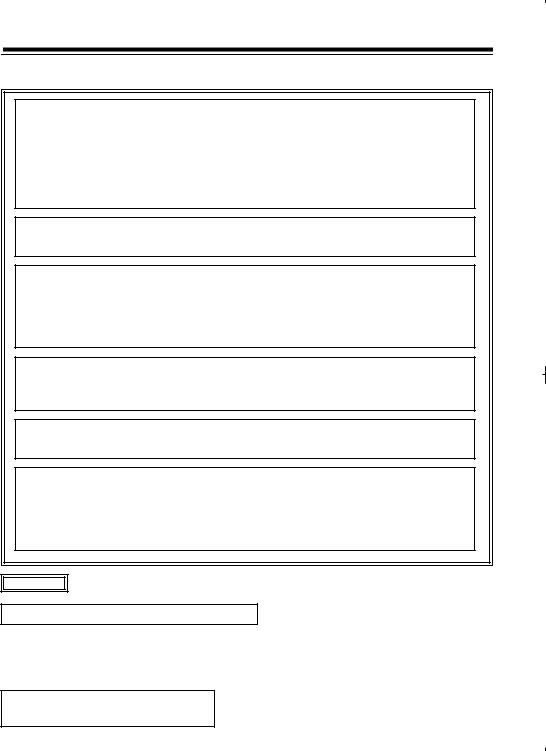
About the RET Signal
The RET signal input to the base station can be transferred to this unit.
When the video format of the camera recorder is HD format, both of the video signals supplied to the RET IN SDI connector and the RET IN VIDEO connector of the base station are transferred to this unit. When the video format of the camera recorder is SD format, either of the video signals supplied to the RET IN SDI connector or the RET IN VIDEO connector of the base station can be transferred to this unit. The signal output from the VF OUT connector (D-Sub connector) of this unit can be switched by the RET switching switch at the rear panel of the base station.
|
|
AG-BS300P/E |
|
AG-CA300G |
|
Video format of the |
Input signal |
|
RET signal |
VF OUT connector |
RET OUT |
camera recorder |
Input signal |
selection switch |
connector |
||
|
connector name |
|
at the rear |
(D-sub) |
(BNC) |
|
|
|
|
||
|
|
|
|
|
|
|
RET IN SDI |
HD SDl (signal A) |
|
HD component |
|
|
|
Composite |
SDI |
|
|
|
RET IN VIDEO |
(signal A) |
|
||
|
(signal B) |
|
|
||
|
|
|
|
|
|
|
RET IN SDI |
HD SDl (signal A) |
|
SD component |
|
|
|
Composite |
VIDEO |
|
|
|
RET IN VIDEO |
(signal B) |
|
||
|
(signal B) |
|
Composite |
||
HD |
|
|
|
||
RET IN SDI |
SD SDl (signal C)* |
|
|
(signal B) |
|
|
|
|
|||
|
RET IN VIDEO |
Composite |
SDI |
Signal is not output |
|
|
(signal B) |
|
|
|
|
|
|
|
|
|
|
|
RET IN SDI |
SD SDl (signal C)* |
|
SD component |
|
|
|
Composite |
VIDEO |
|
|
|
RET IN VIDEO |
(signal B) |
|
||
|
(signal B) |
|
|
||
|
|
|
|
|
|
|
RET IN SDI |
SD SDl (signal A) |
|
SD component |
Composite |
|
|
Composite |
SDI |
||
|
RET IN VIDEO |
(signal A) |
(signal A) |
||
|
(signal B) |
|
|||
|
|
|
|
|
|
|
RET IN SDI |
SD SDl (signal A) |
|
SD component |
|
|
|
Composite |
VIDEO |
|
|
|
RET IN VIDEO |
(signal B) |
|
||
|
(signal B) |
|
|
||
SD |
|
|
|
|
|
RET IN SDI |
HD SDl (signal C)* |
|
|
Composite |
|
|
|
|
|||
|
RET IN VIDEO |
Composite |
SDI |
Signal is not output |
|
|
(signal B) |
|
|
(signal B) |
|
|
|
|
|
|
|
|
RET IN SDI |
HD SDl (signal C)* |
|
SD component |
|
|
|
Composite |
VIDEO |
|
|
|
RET IN VIDEO |
(signal B) |
|
||
|
(signal B) |
|
|
||
|
|
|
|
|
|
* (signal C) shows that it is a signal which cannot be transferred.
E-13

Mounting to the Camera Recorder
Mount the unit to a camera recorder using the following procedure:
<Notes> |
|
|
|
z When connecting this unit to the camera recorder, set the GENLOCK in the GENLOCK menu of the |
ENGLISH |
||
camera recorder to "EXT". However, it is not necessary to set this with the AG-HPX300/301/302/304 |
|||
|
|||
and the AG-HPX500/502. |
|
|
|
z It may be required to update the version of the software for the camera recorder depending on the |
|
||
version used by the camera recorder. Consult the dealer. |
|
||
1 Align the guides at the back of the camera |
4 Connect one end of the power cable |
|
|
recorder with the guides of the unit, and push |
connected to the base station to the DC IN |
|
|
it in the direction of the arrow securely. |
24 V connector of the unit. |
|
|
|
5 Connect the REMOTE connector of the unit |
|
|
|
with the REMOTE connector of the camera |
|
|
|
recorder using the included REMOTE cable. |
|
|
3
2 Connect the GENLOCK OUT connector of this unit with the GENLOCK IN connector of the camera recorder using a BNC cable (commercially available) of 50 cm or shorter.
3 Mount the supplied ferrite core on the BNC |
5 |
2 |
cable within 15 cm from the SDI connector of |
|
|
the camera recorder. |
|
|
Connect the SDI IN connector of this unit with |
|
|
the SDI OUT connector of the camera |
|
|
recorder* using a BNC cable (commercially |
|
|
available; 3C-FW) of 50 cm or shorter. There |
|
|
are camera recorders that display VIDEO |
|
|
OUT, but make sure to set it to SDI signal by |
|
4 |
the menu settings or switch settings before |
|
|
connecting. |
|
|
*If the output connector of the camera recorder is set to SDI, any connector can be used.
E-14

Fixing the Connector Cover
Fix the connector cover as explained below when this unit is used with the power cables connected.
1 Fix the included cable strap onto the power supply cables.
2 After connecting the DC IN 24 V connector cover of this unit with the connector cover of the power supply cables, fix it to the connector of the power supply cables using the cable strap.
E-15
 Loading...