


Operating Instructions
Memory Card Camera-Recorder
Model No. AG-CX350
Before using this product, be sure to read “Read this first!” (pages 2 to 6).
Before operating this product, please read the instructions carefully and save this manual for future use.
P |
|
PJ |
|
EN |
|
ED |
|
AN |
|
PX |
|
|
W0219KI0 -YI |
|
|
|
ENGLISH |
||||||||
|
|
|
|
|
|
|
|
|
|
|
|
DVQP1830ZA |
Read this first!
Read this first!


 indicates safety information.
CAUTION |
RISK OF ELECTRIC SHOCK |
DO NOT OPEN |
CAUTION: TO REDUCE THE RISK OF ELECTRIC SHOCK, |
DO NOT REMOVE COVER (OR BACK). |
NO USER-SERVICEABLE PARTS INSIDE. |
REFER TO SERVICING TO QUALIFIED SERVICE PERSONNEL. |
The lightning flash with arrowhead symbol, within an equilateral triangle, is intended to alert the user to the presence of uninsulated “dangerous voltage” within the product’s enclosure that may be of sufficient magnitude to constitute a risk of electric shock to persons.
The exclamation point within an equilateral triangle is intended to alert the user to the presence of important operating and maintenance (servicing) instructions in the literature accompanying the appliance.
CAUTION:
Danger of explosion or fire if battery is incorrectly replaced or mistreated.
•Do not disassemble the battery or dispose of it in fire.
•Do not store in temperatures over 60°C (140°F).
•Do not expose the battery to excessive heat such as sunshine, fire or the like.
For Battery Pack
•Use specified charger.
•Replace only with same or specified type.
CAUTION:
In order to maintain adequate ventilation, do not install or place this unit in a bookcase, builtin cabinet or any other confined space. To
prevent risk of electric shock or fire hazard due to overheating, ensure that curtains and any other materials do not obstruct the ventilation.
WARNING:
•To reduce the risk of fire or electric shock, do not expose this equipment to rain or moisture.
•To reduce the risk of fire or electric shock, keep this equipment away from all liquids. Use and store only in locations which are not exposed to the risk of dripping or splashing liquids, and do not place any liquid containers on top of the equipment.
WARNING:
Always keep memory cards (optional accessory) or accessories (microphone holder screws) out of the reach of babies and small children.
CAUTION:
To reduce the risk of fire or electric shock and annoying interference, use the recommended accessories only.
CAUTION:
The mains plug of the power supply cord shall remain readily operable.
The AC receptacle (mains socket outlet) shall be installed near the equipment and shall be easily accessible.
To completely disconnect this equipment from the AC mains, disconnect the power cord plug from the AC receptacle.
CAUTION:
Excessive sound pressure from earphones and headphones can cause hearing loss.
CAUTION:
Do not lift the unit by its handle while the tripod is attached. When the tripod is attached, its weight will also affect the unit’s handle, possibly causing the handle to break and hurting the user. To carry the unit while the tripod is attached, take hold of the tripod.
CAUTION:
Do not leave the unit in direct contact with the skin for long periods of time when in use.
Low temperature burn injuries may be suffered if the high temperature parts of this unit are in direct contact with the skin for long periods of time.
When using the equipment for long periods of time, make use of the tripod.
CAUTION:
Keep metal objects (such as necklaces and hairpins) away from the battery. Short-circuiting may occur across the terminals, causing the battery to heat up, and you may
seriously burn yourself if you touch the battery in this state.
CAUTION:
Do not jar, swing, or shake the unit by its handle while the conversion lens or another accessory is attached.
Due to the added weight of the conversion lens, any strong jolt to the handle may damage the unit or result in personal injury.
– 2 –

Read this first!


 indicates safety information.
CAUTION:
This apparatus can be operated at a voltage in the range of 100-240 V AC. Voltages other than 120 V are not intended for U.S.A. and Canada.
Operation at a voltage other than 120 V AC may require the use of a different AC plug. Please contact either a local or foreign Panasonic authorized service center for assistance in selecting an alternate AC plug.
FCC NOTICE (USA)
Supplier’s Declaration of Conformity
Trade Name: |
Panasonic |
Model Number: |
AG-CX350 |
Responsible Party: |
Panasonic Corporation of North America |
|
Two Riverfront Plaza Newark NJ07102 |
Support contact: |
1-800-524-1448 |
This device complies with Part 15 of the FCC Rules. Operation is subject to the following two conditions:
(1) This device may not cause harmful interference, and (2) this device must accept any interference received, including interference that may cause undesired operation.
FCC Warning:
To assure continued FCC emission limit compliance, follow the attached installation instructions and the user must use only shielded interface cables when connecting to host computer or peripheral devices. Also, any unauthorized changes or modifications to this equipment could void the user’s authority to operate this device.
FCC Caution:
This equipment has been tested and found to comply with the limits for a Class B digital device, pursuant to Part 15 of the FCC Rules. These limits are designed to provide reasonable protection against harmful interference in a residential installation. This equipment generates, uses and can radiate radio frequency energy and, if not installed and used in accordance with the instructions, may cause harmful interference to radio communications. However, there is no guarantee that interference will not occur in a particular installation. If this equipment does cause harmful interference to radio or television reception, which can be determined by turning the equipment off and on, the user is encouraged to try to correct the interference by one or more of the following measures:
ffReorient or relocate the receiving antenna.
ffIncrease the separation between the equipment and receiver.
ffConnect the equipment into an outlet on a circuit different from that to which the receiver is connected.
ffConsult the dealer or an experienced radio/TV technician for help. The user may find the booklet “Something About Interference” available from FCC local regional offices helpful.
NOTIFICATION (Canada)
CAN ICES-3(B)/NMB-3(B)
The rating plate is on the underside of the Camera Recorder, Battery Charger and AC Adaptor.
– 3 –

Read this first!
IMPORTANT SAFETY INSTRUCTIONS
1)Read these instructions.
2)Keep these instructions.
3)Heed all warnings.
4)Follow all instructions.
5)Do not use this apparatus near water.
6)Clean only with dry cloth.
7)Do not block any ventilation openings. Install in accordance with the manufacturer’s instructions.
8)Do not install near any heat sources such as radiators, heat registers, stoves, or other apparatus (including amplifiers) that produce heat.
9)Do not defeat the safety purpose of the polarized or grounding-type plug. A polarized plug has two blades with one wider than the other. A grounding-type plug has two blades and a third grounding prong. The wide blade or the third prong are provided for your safety. If the provided plug does not fit into your outlet, consult an electrician for replacement of the obsolete outlet.
10)Protect the power cord from being walked on or pinched particularly at plugs, convenience receptacles, and the point where they exit from the apparatus.
11)Only use attachments/accessories specified by the manufacturer.
12)Use only with the cart, stand, tripod, bracket, or table specified by the manufacturer, or sold with the apparatus. When a cart is used, use caution when moving the cart/ apparatus combination to avoid injury from tip-over.
13)Unplug this apparatus during lightning storms or when unused for long periods of time.
14)Refer all servicing to qualified service personnel. Servicing is required when the apparatus has been damaged 

 in any way, such as power-supply cord or plug is damaged, liquid has been spilled or objects have fallen into the apparatus, the apparatus has been exposed to rain or moisture, does not operate normally, or has been dropped.
For USA and Canada
A lithium ion/polymer battery that is recyclable powers the product you have purchased. Please call 1-800-8-BATTERY for information on how to recycle this battery.
– 4 –
Read this first!
Brazil Only
Brasil Apenas
rrManuseio de baterias usadas
BRASIL
Após o uso, as pilhas e /ou baterias poderão ser entregues ao estabelecimento comercial ou rede de assistência técnica autorizada.
Cobrir os terminais positivo (+) e negativo (-) com uma fita isolante adesiva, antes de depositar numa caixa destinada para o recolhimento. O contato entre partes metálicas pode causar vazamentos, gerar calor, romper a blindagem e produzir fogo.
Não desmonte, não remova o invólucro, nem amasse a bateria. O gás liberado pela bateria pode irritar a garganta, danificar o lacre do invólucro ou o vazamento provocar calor, ruptura da blindagem e produzir fogo devido ao curto circuito dos terminais. Não incinere nem aqueça as baterias, elas não podem ficar expostas a temperaturas superiores a 100°C (212°F). O gás liberado pela bateria pode irritar a garganta, danificar o lacre do invólucro ou o vazamento provocar calor, ruptura da blindagem e produzir fogo devido ao curto circuito dos terminais provocado internamente.
Evite o contato com o liquido que vazar das baterias. Caso isto ocorra, lave bem a parte afetada com bastante água. Caso haja irritação, consulte um médico.
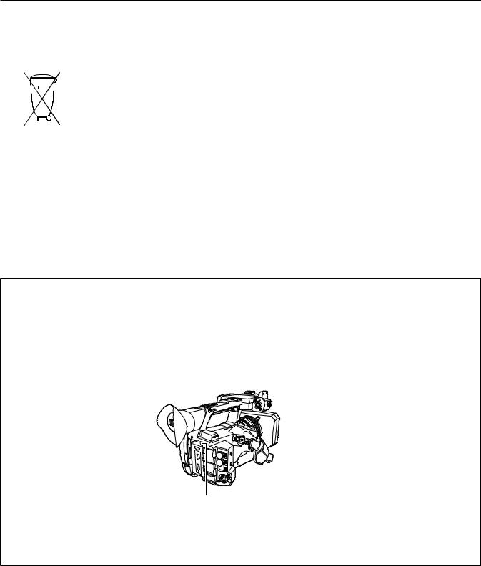
To remove the battery
Para remover a bateria
Main Power Battery (Lithium ion Battery) Bateria Principal de Energia
(Refer to page 32 for the detail.)
Press the battery release button. Pressione o botão para liberar a bateria.
Battery release button
Botão de liberação da bateria
Back-up Battery (Lithium Battery)
• For the removal of the battery for disposal at the end of its service life, please consult your dealer.
– 5 –

Read this first!
rr Batteries that may be used with this product (as of February 2019)
Panasonic AG-VBR59 / AG-VBR89 / AG-VBR118 / VW-VBD58 batteries may be used with this product.
It has been found that counterfeit battery packs which look very similar to the genuine product are made available to purchase in some markets. Some of these battery packs are not adequately protected with internal protection to meet the requirements of appropriate safety standards. There is a possibility that these battery packs may lead to fire or explosion. Please be advised that we are not liable for any accident or failure occurring as a result of use of a counterfeit battery pack. To ensure that safe products are used we would recommend that a genuine Panasonic battery pack is used.
Battery Charger / AC Adaptor
Disconnect the AC mains plug from the AC mains socket when not in use.
Information on Disposal in other Countries outside the European Union
|
|
|
|
EU |
These symbols are only valid in the European Union. If you wish to discard these items, please contact your |
|||
|
|
|
|
|
|
|
|
|
|
|
|
|
|
|
|
|
local authorities or dealer and ask for the correct method of disposal. |
|
|
|
|
|
|
|
|
|
|
|
|
|
|
|
|
|
|
|
|
|
|
|
|
|
|
|
rr The symbols on this product (including the accessories) represent the following:
dAC
eDC ON
Standby (OFF)
Class II equipment (The construction of the product is double-insulated.)
– 6 –

Trademark
ffSDXC logo is a trademark of SD-3C, LLC.
ffAVCHD, AVCHD Progressive, and AVCHD Progressive logo are trademarks of Panasonic Corporation and Sony Corporation.
ffThis is manufactured based on license from Dolby Laboratories, Inc. Dolby, Dolby Audio, and the double-D symbol are trademarks of Dolby Laboratories.
ffThe terms HDMI and HDMI High-Definition Multimedia Interface, and the HDMI Logo are trademarks or registered trademarks of HDMI Licensing Administrator, Inc. in the United States and other countries.
ffMicrosoft® and Windows® are registered trademarks or trademarks of Microsoft Corporation in the United States and/or other countries. ffScreenshots are used according to Microsoft Corporation guidelines.
ffIntel®, Pentium®, Celeron®, and Intel® CoreTM are trademarks of Intel Corporation in the United States and/or other countries. ffMac and Mac OS are trademarks of Apple Inc. registered in the United States and/or other countries.
ffiPad is a trademark of Apple Inc. registered in the United States and/or other countries. ffApp Store is a service mark of Apple Inc.
ffAndroid and Google Play are trademarks or registered trademarks of Google LLC. ffWi-Fi® is a registered trademark of Wi-Fi Alliance®.
ffWPATM and WPA2TM are trademark of Wi-Fi Alliance®. ffNDI® is a registered trademark of NewTek, Inc.
ffAll other names, company names, product names, etc., contained in this instruction manual are trademarks or registered trademarks of their respective owners.
License
ffThis product is licensed under the AVC Patent Portfolio License. All other acts are not licensed except private use for personal and non-profit purposes such as what are described below.
-- To record video in compliance with the AVC standard (AVC Video)
-- To play back AVC Video that was recorded by a consumer engaged in a personal and non-commercial activity -- To play back AVC Video that was obtained from a video provider licensed to provide the video
Visit the MPEG LA, LLC website (http://www.mpegla.com/) for details.
ffSeparate license contract with MPEG-LA is required to record in a memory card with this product and to distribute that card to end users for a profit. The end user mentioned here indicates a person or organization that handles contents for a personal use.
Software information about this product
1This product includes software licensed under GNU General Public License (GPL) and GNU Lesser General Public License (LGPL), and customers are hereby notified that they have rights to obtain, re-engineer, and redistribute the source code of these software.
2 This product includes software licensed under MIT-License.
3 This product includes software developed by the OpenSSL Project for use in the OpenSSL Toolkit (http://www.openssl.org/).
4This product includes software licensed under OpenBSD License.
5This software is based in part on the work of the Independent JPEG Group.
6This product includes software licensed under the MOZILLA PUBLIC LICENSE.
For details on each license, refer to the terms of license.
The terms of license can be displayed using the following method.
ffSelect the [OTHERS] menu → [USB DEVICE] → [SERVICE MODE] → [YES]. Select “LICENSE.TXT” in the external drive recognized by the computer.
For details on these descriptions (originally provided in English) and how to obtain the source code, visit the following website. https://pro-av.panasonic.net/
We do not accept inquiries about the details of the source code obtained by the customer.
Excluding the open source software licensed based on GPL/LGPL, etc., transferring, copying, reverse assembling, reverse compiling, and reverse engineering of the software included in the camera is prohibited. Also, exporting of any software included in the camera against the export laws and regulations is prohibited.
How to read this document
rr Illustrations
ffIllustrations of the product appearance, menu screens, etc., may vary from the actual.
rr Conventions used in this manual
ffWords and phrases in [ ] brackets indicate content displayed in the LCD monitor.
ffWords and phrases in < > brackets indicate design text used on this camera, such as button names.
rr Reference pages
ffReference pages in this document are indicated by (page 00).
rr Terminology
ffSD memory card, SDHC memory card, and SDXC memory card are referred to only as “SD card” unless distinguished otherwise. ffA memory card with the “microP2” logo such as AJ P2M064BG (optional) is referred to as a “microP2 card”.
ffSD card and microP2 card are referred to only as a “memory card” unless distinguished otherwise. ffVideo that is created during a single recording operation is referred to as a “clip”.
– 7 –

Contents
Contents
Read this first! 2
Chapter 1 Overview |
|
10 |
Before using the camera |
|
11 |
Accessories |
|
14 |
When turning on the power for the first time |
|
15 |
[AREA SETTINGS] |
|
15 |
[TIME ZONE] |
|
16 |
[CLOCK SETTING] |
|
16 |
Use of the camera on a system |
|
17 |
Basic configuration devices |
|
17 |
Expanded configuration devices |
|
17 |
What you can do with this camera |
|
18 |
Recording to the memory card |
|
18 |
Linking to external devices |
|
18 |
Connecting to the network |
|
19 |
Chapter 2 Description of Parts |
|
20 |
Camera |
|
21 |
Left side |
|
21 |
Right side |
|
22 |
Front side |
|
24 |
Rear side |
|
25 |
Top side |
|
26 |
Basic operation |
|
28 |
Multidial operation |
|
28 |
Touch operation of the LCD monitor |
|
28 |
Chapter 3 |
Preparation |
|
29 |
Power supply |
|
|
30 |
Charging the battery |
|
30 |
|
Attaching and removing the battery |
|
32 |
|
Using the AC adaptor |
|
33 |
|
Mounting accessories |
|
34 |
|
Adjusting the grip belt |
|
34 |
|
Attaching the shoulder strap |
|
34 |
|
Mounting the lens hood |
|
34 |
|
Mounting the eye cup |
|
35 |
|
Mounting the external microphone |
|
36 |
|
Attaching a tripod |
|
36 |
|
Mounting accessories |
|
37 |
|
Turning on/off the power |
|
38 |
|
How to turn on the power |
|
38 |
|
How to turn off the power |
|
38 |
|
Charging the built-in battery |
|
39 |
|
Setting the date/time of the internal clock |
|
40 |
|
Preparing the memory card |
|
41 |
|
Memory cards supported by the camera |
|
41 |
|
Preventing unintentional erasing |
|
41 |
|
Status of the card access lamp and memory card |
|
42 |
|
Inserting/removing the memory card |
|
42 |
|
Formatting the memory card |
|
43 |
|
Recording time of the memory card |
|
43 |
|
Handling the recording data |
|
44 |
|
Setting of time data |
|
47 |
|
Definition of time data |
|
47 |
|
User bits settings |
|
47 |
|
Setting the time code |
|
48 |
|
Presetting the time code to external |
|
49 |
|
Supplying the time code externally |
|
50 |
|
Assigning function to the USER buttons |
|
51 |
|
Functions assigned to USER buttons |
|
51 |
|
Checking the function assigned to the USER buttons |
|
52 |
|
Adjusting and setting the LCD monitor |
|
53 |
|
Using the LCD monitor |
|
53 |
|
Adjusting the LCD monitor |
|
53 |
|
Mirror shooting |
|
53 |
|
Adjusting and setting the viewfinder |
|
54 |
|
Using the viewfinder |
|
54 |
|
Adjusting the viewfinder |
|
54 |
|
Tally lamp |
|
|
55 |
Chapter 4 Operation |
|
56 |
Basic operation of the screen |
|
57 |
Major button operation and screen display |
|
57 |
Major button operation and switching screen |
|
58 |
Operating each screen |
|
59 |
Camera image screen |
|
59 |
Thumbnail screen |
|
59 |
Operation icon screen |
|
59 |
Basic operation of the menu |
|
60 |
Configuration of the menu |
|
60 |
Displaying the menu |
|
61 |
Operating the menu |
|
62 |
Initializing the menu |
|
63 |
Menu settings |
|
64 |
[THUMBNAIL] menu |
|
64 |
[CAMERA] menu |
|
64 |
[SCENE FILE] menu |
|
68 |
[AUDIO] menu |
|
78 |
[VIDEO OUT/LCD/VF] menu |
|
79 |
[RECORDING] menu |
|
88 |
[NETWORK] menu |
|
90 |
[SYSTEM] menu |
|
95 |
[OTHERS] menu |
|
96 |
[OPTION] menu |
|
98 |
Factory setting value of the scene file |
|
99 |
[SCENE FILE] menu |
|
99 |
Target items for scene file/setup file/initialization |
|
102 |
[THUMBNAIL] menu |
|
102 |
[CAMERA] menu |
|
102 |
[SCENE FILE] menu |
|
103 |
[AUDIO] menu |
|
105 |
[VIDEO OUT/LCD/VF] menu |
|
105 |
[RECORDING] menu |
|
106 |
[NETWORK] menu |
|
107 |
[SYSTEM] menu |
|
107 |
[OTHERS] menu |
|
108 |
[OPTION] menu |
|
108 |
Handling setting data |
|
109 |
Scene files |
|
109 |
Setup file |
|
110 |
Chapter 5 |
Shooting |
|
112 |
Shooting |
|
|
113 |
Selecting the resolution, codec, and frame rate for recording |
|
|
|
video |
|
|
113 |
Adjustable settings when shooting |
|
115 |
|
Iris |
|
|
115 |
Gain |
|
|
115 |
Super gain |
|
|
115 |
Brightness adjustment |
|
115 |
|
Macro |
|
|
115 |
Focusing (manual focus) |
|
115 |
|
Area mode function |
|
116 |
|
Adjusting the white and black balance |
|
117 |
|
White balance adjustment |
|
117 |
|
Black balance adjustment |
|
118 |
|
Using the zoom function |
|
120 |
|
Adjusting the zoom position |
|
120 |
|
Image quality adjustment |
|
121 |
|
Detail function |
|
121 |
|
Skin tone function |
|
121 |
|
RB gain control function |
|
121 |
|
Chroma setting function |
|
122 |
|
Matrix function |
|
122 |
|
Color correction function |
|
123 |
|
Black control function |
|
123 |
|
Gamma function |
|
123 |
|
Knee function |
|
124 |
|
White clip function |
|
124 |
|
Variable frame rate (VFR) recording function/super slow |
|
|
|
recording function |
|
125 |
|
Variable frame rate (VFR) |
|
125 |
|
Super slow |
|
|
125 |
Audio input |
|
|
126 |
Switching the audio input |
|
126 |
|
When using the built-in microphone |
|
126 |
|
When using an audio device or an external microphone |
|
126 |
|
Adjusting the audio recording level |
|
126 |
|
Monitoring the audio |
|
127 |
|
Confirming audio input setting |
|
127 |
|
Special recording function |
|
128 |
|
Pre-recording |
|
128 |
|
– 8 –

Contents
Relay recording |
|
128 |
Simultaneous recording |
|
129 |
Background recording |
|
129 |
Interval recording |
|
131 |
IR recording |
|
131 |
Convenient shooting functions |
|
132 |
Zebra patterns display |
|
132 |
Displaying the center marker |
|
132 |
Displaying the safety zone marker |
|
133 |
Displaying frame marker |
|
133 |
Focus assist function |
|
133 |
Optical image stabilizer function |
|
135 |
Dynamic range stretcher function |
|
135 |
Time stamp function |
|
135 |
Waveform monitor function |
|
136 |
Digital zoom function |
|
136 |
Level gauge |
|
137 |
Color bars |
|
137 |
Operation icon screen display |
|
138 |
Displaying the operation icon screen |
|
138 |
Multi manual function |
|
139 |
Displaying the operation icon screen |
|
139 |
Setting the variable value for the white balance |
|
139 |
Setting the shutter speed |
|
139 |
Setting the synchro scan shutter speed |
|
139 |
Setting the frame rate of the variable frame rate recording |
|
|
function |
|
140 |
Adjusting the area size/area position of the area mode |
|
|
function |
|
140 |
Adjusting the width of the auto focus area |
|
140 |
Chapter 6 Playback |
|
141 |
Thumbnail operation |
|
142 |
Thumbnail operation overview |
|
142 |
Thumbnail screen |
|
142 |
Copying clips |
|
145 |
Deleting clips |
|
146 |
Protecting clips |
|
146 |
Restoring clips |
|
147 |
Playing back clips |
|
148 |
Useful playback function |
|
150 |
Resume play |
|
150 |
Still image recording function |
|
151 |
Chapter 7 Output and Screen Display |
|
152 |
Output format |
|
153 |
Format that can be output from the <SDI OUT> terminal |
|
153 |
Format that can be output from the <HDMI> terminal |
|
153 |
Screen status display |
|
155 |
Screen display during shooting |
|
155 |
Screen display during playback |
|
159 |
Checking and displaying shooting status |
|
160 |
Mode check display |
|
161 |
Connecting to the CX ROP application |
|
177 |
Operation while the CX ROP app is connected |
|
177 |
Streaming function |
|
178 |
Camera settings |
|
178 |
Starting streaming with an operation from the application |
|
|
software |
|
179 |
Starting streaming with an operation on the camera |
|
179 |
NDI|HX function |
|
181 |
Camera settings |
|
181 |
Chapter 10 Notes |
|
183 |
Frequently asked questions |
|
184 |
Power supply |
|
184 |
Battery |
|
184 |
Battery charger |
|
184 |
Memory card |
|
184 |
Shooting |
|
184 |
Playback |
|
185 |
Others |
|
185 |
Warning system |
|
186 |
Cases indicated by error messages |
|
186 |
Recording function that cannot be used simultaneously |
|
190 |
Updating the camera firmware |
|
191 |
Cleaning and storing |
|
192 |
Cleaning the camera body |
|
192 |
Cautions when storing the camera recorder |
|
192 |
Chapter 11 Specification |
|
193 |
Dimensions |
|
194 |
Specifications |
|
195 |
General |
|
195 |
Camera unit |
|
195 |
Memory card recorder |
|
196 |
Digital video |
|
196 |
Digital audio |
|
197 |
Streaming |
|
197 |
Video output |
|
197 |
Audio input/output |
|
197 |
Other input/output |
|
197 |
Monitor |
|
198 |
AC adaptor |
|
198 |
Battery charger (AG BRD50) |
|
198 |
Battery pack (AG VBR59) |
|
198 |
Index |
|
199 |
Chapter 8 Connecting to External Devices |
|
163 |
Connecting with headphones and TV/monitor |
|
164 |
Headphones |
|
164 |
Remote control |
|
164 |
TV/monitor |
|
165 |
Connection function via the <USB3.0 DEVICE>/<USB2.0 |
|
|
HOST> terminal |
|
166 |
Connection with a computer in card reader mode |
|
166 |
Remote operation by iPad or Android terminal |
|
167 |
Chapter 9 Network Connection |
|
168 |
Network connection |
|
169 |
Available functions |
|
169 |
Preparing for connection |
|
170 |
For the wireless module |
|
170 |
For the wired LAN |
|
170 |
Network settings |
|
171 |
Wireless LAN settings |
|
171 |
Wired LAN settings |
|
172 |
Specifying the network settings using the settings tool |
|
173 |
Confirming the network status |
|
175 |
Connecting to the iPad or Android terminal |
|
176 |
Mounting the wireless module |
|
176 |
Camera settings |
|
176 |
Preparing the CX ROP app |
|
176 |
– 9 –

Chapter 1 Overview
Before using the camera, read this chapter.
Chapter 1 Overview — Before using the camera
Before using the camera
rr Before using the camera, always check if the built-in battery is not consumed, and then set the date/time.
The date of the internal clock of the camera resets to January 1, 2019 if the built-in battery is exhausted. This may result in the meta data of the clip not being recorded correctly, and it may not display correctly in the thumbnail screen.
Connect the AC adaptor to the camera or mount a battery when recharging the built-in battery.
The date/time set on the camera is maintained for approximately four months when left in this state for approximately 24 hours. (The built-in battery is charged even when the power switch is set to < j > (ON))
For details about setting the time zone and date/time, refer to [TIME ZONE] (page 16) and [CLOCK SETTING] (page 16).
rr When using this product during rain or snow or when at the beach, be careful that water does not get inside the camera.
Water causes damage to the camera and memory card. (Repair may be impossible)
rr Keep the camera away from devices that produce magnetism (TVs, TV games, etc.).
ffDo not use the camera on top of a TV or around it. Image or audio of the camera may be distorted by the electromagnetic wave emitted from a TV. ffThe recorded content may be damaged or image may be distorted by a strong magnetic field produced by speaker or large motor.
ffDo not use the camera on top of a microcomputer or around it. Image or audio of the camera may be distorted by the electromagnetic wave emitted from a microcomputer.
ffThe camera may not operate properly due to a harmful effect from a device producing magnetism. In such case, turn off the camera and either remove the battery or unplug the AC adaptor from the power outlet. Then, mount the battery or connect the AC adaptor again. After that, turn on the camera.
rr Do not use the camera near a radio transmitter or high-voltage device.
Using the camera recorder near a radio transmitter or high-voltage device may cause harmful effect to the recorded video or audio.
rr Take care so sand and/or dust do not get inside the camera when using the camera at the beach, etc.
Sand and dust may damage the camera and memory card. (Be careful when inserting or removing the memory card)
rr AC adaptor, battery charger, and battery
ffIt may take more time to charge or may not be able to charge when the temperature of the battery is extremely high or extremely low.
ffWhen the charging lamp continues to flash in orange, check if there is any debris, foreign object, or dirt attached to the terminal section of the battery or the battery charger, and reconnect it correctly. Always disconnect the power plug from the power outlet before removing the debris, foreign object, or dirt attached to the terminal section.
ffThe charging lamp will flash in orange when the temperature of the battery is extremely high or low. Then, charging will start automatically after the battery reaches chargeable temperature.
ffIf the charging lamp continues to flash even when the battery is at its optimal temperature, the battery or battery charger may be damaged. Consult the dealer.
ffNoise may be generated in radio when the camera is used close to a radio (especially when receiving AM). Keep a distance of 1 m or more when using.
ffOscillating sound may generate inside the AC adaptor or the battery charger during the use, but this is not a malfunction.
ffAlways disconnect the power plug from the power outlet after the use. (Power of approximately 0.1 W is consumed by the AC power itself if kept connected)
ffDo not get the terminal section of the AC adaptor, the battery charger, or the battery dirty. Install the device close to the power outlet so the disconnection device (power plug) can be easily reached.
rr Memory cards
ffThe surface of camera or the memory card may get slightly hot when used for a long period of time, but this is not a malfunction. ffThe amount of memory included on the label of the memory card is the total amount of memory below.
-- Capacity to protect and manage copyright
-- Capacity usable as the normal memory on the camera or a PC. ffDo not give a strong impact to, bend, or drop the memory card.
ffMemory card data may become destroyed or erased in the following cases.
-- Electrical noise or static electricity
-- Malfunction of the camera or the memory card
ffDo not perform the following operations when accessing the memory card (the card 1 access lamp/card 2 access lamp is flashing in orange).
-- Removing the memory card
-- Disconnecting battery or the AC adaptor without turning off the camera -- Apply vibration of impact
rr Take care not to drop the camera when carrying the camera. ffStrong impact will damage the camera, and it may not operate properly. ffHold the handle or grip when carrying the camera, and handle it carefully.
rr Do not apply insecticide or volatile material to the camera.
ffThe camera may deform or the paint may peel off when insecticide or volatile material is applied. ffDo not allow the camera to remain in contact with a rubber or vinyl object for a long period of time.
– 11 –

Chapter 1 Overview — Before using the camera
rr Disconnect the battery or disconnect the AC cable from the power outlet after the use.
rr Battery characteristics
The battery is a rechargeable lithium-ion battery. It produces electrical energy via an internal chemical reaction. This chemical reaction is effected by the ambient temperature and humidity. The usable time of the battery becomes shorter when the temperature gets higher or lower. When used in an environment with extremely low temperature, it can only be used for approximately five minutes.
When the battery is in an extremely hot environment, its protective function will operate and the camera recorder cannot be used temporarily.
rr After using the camera recorder, be sure to remove the battery.
Securely remove the battery from the camera.
(Minute current is consumed even if the camera is turned off when the battery is kept mounted)
The battery will become over discharge and may become unusable even if it is recharged when the battery is kept mounted for long period of time. Do not remove the battery when the power is turned on.
Turn off the power and remove the battery after the operation lamp goes completely out.
rr Take proper care of the battery terminal.
Do not allow dust or foreign objects on the battery terminal.
Confirm that the battery and its terminal section is not deformed when the battery is dropped by mistake.
Do not mount the deformed battery into a camera or mount to the battery charger. This may damage the camera or the battery charger.
rr Cautions when throwing memory cards away or transferring them to others
Formatting memory cards or deleting data using the functions of the camera or a computer will merely change the file management information: it will not completely erase the data on the cards.
It is recommended to completely erase the data in following method when discarding/conveying. ffPhysically destroy the memory card itself
ffCompletely erase the data in the memory card using a commercially available data erasing software for PC, etc. Users are responsible for managing the data stored in their memory card.
rr LCD monitor and viewfinder
ffDo not continuously display the same image or text on the LCD monitor for a long period of time. The image may be burned on to the screen. It will return to normal after leaving the camera recorder turned off for several hours.
ffCondensation sometimes forms on the LCD panel of the LCD monitor in locations subject to extreme temperature differences. If this happens, wipe with a soft, dry cloth.
ffThe LCD monitor will be slightly darker than normal immediately after the power is turned on when the camera is very cold. It will return to its regular brightness when the internal temperature increases.
ffThe LCD monitor and viewfinder (organic EL) are managed with high precision so that at least 99.99% of the dots are effective pixels and 0.01% or less are invalid pixels and always lit. This is not a malfunction and it has no effect whatsoever on the recorded images.
ffThe viewfinder for this camera uses an organic EL. The image may burn into the screen if the same image or letters are left displayed on the screen for a long time. There is no problem with the recorded images.
Switch the screen by turning off the screen or by using the eye sensor, etc.
ffIt may become difficult to see or difficult to recognize the touch when a LCD protection sheet is affixed.
rr Caution regarding laser beams
The MOS sensor may be damaged if the MOS sensor is subjected to light from a laser beam.
Take sufficient care to prevent laser beams from striking the lens when shooting in an environment where laser devices are used.
rr Note the following points.
ffIf you prepare to record important images, always shoot some advance test footage to verify that both pictures and sound are being recorded normally.
ffPanasonic will not assume liability when video or audio recording fails due to a malfunction of the camera or the memory card during the use.
ffSet the calendar (datetime of the internal clock) and the time zone, or check the setting before recording. This will have an effect on the management of the recorded contents.
rr Exemption of liability
Panasonic is not liable in any way regarding following.
1 Incidental, special, or consequential damages caused directly or indirectly by the camera 2 Damages, breakage of the camera, etc., caused by misuse or carelessness of the customer 3 When disassembly, repair, or modification of the camera is performed by the customer
4Inconveniences, damnification, or damages by not being able to record and/or display the video due to any reasons including failure or malfunction of the camera
5Inconveniences, damnification, or damages resulting from malfunction of the system combining with any third party equipment
6A liability claim or any claim for a privacy violation by an individual or a group that was the subject of the video that the customer has shot (including recording) that became public by any reason (including using with the network user authentication turned OFF)
7The registered information is lost due to any reason (including initializing this camera because the authentication information such as user name or password is forgotten)
rr Cautions regarding network
Since this camera is used connected to a network, following mischief may occur.
1 Leaking or divulging of information through the camera
2 Fraudulent operation of the camera by a malicious third party
– 12 –

Chapter 1 Overview — Before using the camera
3 Obstruction and/or stopping of the camera by a malicious third party
It is customer’s responsibility to take sufficient network security measures including the following to prevent damage caused by such mischief. Please note that Panasonic is not liable in any way for damage caused by such mischief.
ffUse the camera on a network where safety is secured by using a firewall, etc.
ffWhen using the camera on a system where a PC is connected, make sure that checking and cleaning of infection by computer virus and malicious program is performed periodically.
ffIn order to prevent malicious attacks, use the authentication system and change the default setting values by using 8 characters or more including 3 or more character types for the authentication information (such as user name and password) so that a third party cannot guess your authentication information.
ffStore the authentication information (user name, password, etc.) appropriately so it is not visible to the third party.
ffPeriodically change the authentication information (user name, password, etc.) and do not use the same authentication information as other accounts. ffTo prevent the setting information in the camera to leak to the network, execute measure such as restricting the access with user authentication, etc. ffDo not install in a location where the camera, cable, etc., can be easily damaged.
rr Security
Take caution so the camera or memory card is not stolen, lost, or neglected. Note that Panasonic is not liable to leakage, falsification, or loss of information caused by them.
– 13 –
Chapter 1 Overview — Accessories
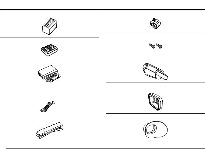
Accessories
Battery (Parts No.: AG VBR59) (page 30)
Battery charger (Parts No.: AG BRD50) (page 30)
AC adaptor (page 30)
Microphone holder (page 36)
Microphone holder screws (page 36) ffLength 12 mm (x 2)
Grip belt (page 34)
ffAlready mounted to the camera.
AC cable (page 30) |
Lens hood (page 34) |
|
ffAlready mounted to the camera. |
||
ffFor AC adaptor |
||
|
|
Eye cup (page 35) |
|
Shoulder strap (page 34) |
||
|
@@NOTE
tt Appropriately discard the AC cable cap (if attached) and packing materials after taking the product out.
– 14 –
Chapter 1 Overview — When turning on the power for the first time
When turning on the power for the first time
The camera is shipped with the region of use not set.
[AREA SETTINGS] is displayed in the LCD monitor when the power is turned on for the first time.
Follow the guidance and make the settings in the order of [AREA SETTINGS], [TIME ZONE], and then [CLOCK SETTING].
ffThere are two methods of operation: a method to operate with the multidial or the <%> button, <(> button, <)> button and <=/&> button, or a method to touch the LCD monitor.
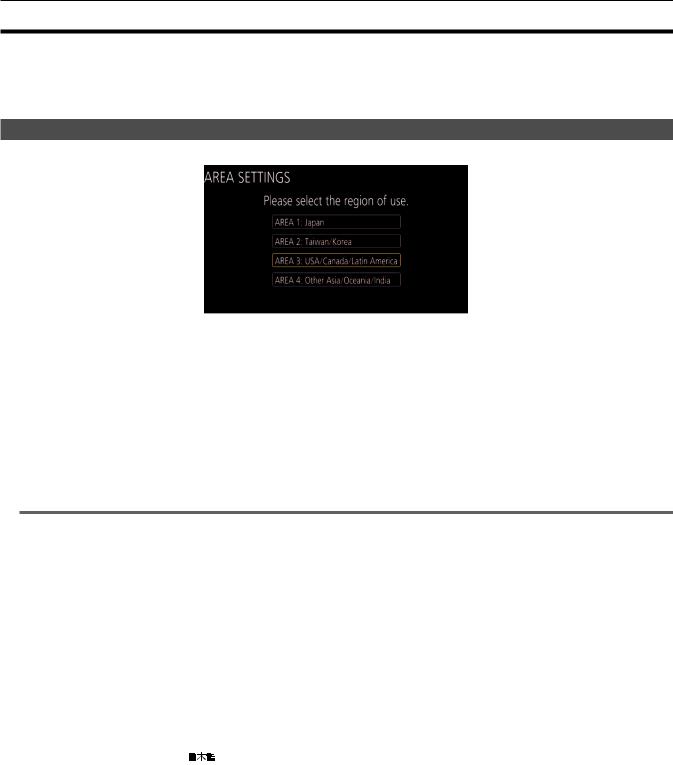
[AREA SETTINGS]
Set the region of use.
1Connect the charged battery or the AC adaptor to the camera, and set the power switch to < j > (ON).
The [AREA SETTINGS] screen is displayed.
2Select the region of use.
[AREA 1]: Japan
[AREA 2]: Taiwan, South Korea
[AREA 3]: United States of America, Canada, Central and South America regions [AREA 4]: Asia region (excluding Japan, Taiwan, South Korea), Oceania region, India
3When the confirmation message is displayed, select [YES].
The camera will be initialized in accordance to the region selected in Step 2. The camera will automatically restart. Once the setting for [AREA SETTINGS] is completed, the [TIME ZONE] screen is displayed.
@@NOTE
tt Once this is set, the [AREA SETTINGS] screen is not displayed from the next startup. tt To change the region of use, set with the [OPTION] menu → [AREA SETTINGS].
rr Setting contents of each region of use
Following setting differs depending on the selected region. ffThe [SYSTEM] menu → [FREQUENCY]
ffThe [SYSTEM] menu → [REC FORMAT]
ffThe [OTHERS] menu → [CLOCK] → [DATE FORMAT]
ffThe [AUDIO] menu → [REC CH SETTINGS] → [HEAD ROOM] ffThe [OTHERS] menu → [LANGUAGE]
Item |
[AREA 1] |
[AREA 2] |
[AREA 3] |
[AREA 4] |
|
[FREQUENCY] |
[59.94Hz] |
[59.94Hz] |
[59.94Hz] |
[50.00Hz] |
|
[REC FORMAT] |
[1080 59.94i/422ALL I 100M] |
[1080 59.94i/422ALL I 100M] |
[1080 59.94i/422ALL I 100M] |
[1080 50.00i/422ALL I 100M] |
|
[DATE FORMAT] |
[Y M D] |
[Y M D] |
[M D Y] |
[D M Y] |
|
[HEAD ROOM] |
[20dB] |
[20dB] |
[20dB] |
[18dB] |
|
[LANGUAGE]* |
[ |
] |
[English] |
[English] |
[English] |
|
|
[Español] |
[Español] |
||
|
[English] |
|
|||
|
|
[Français] |
[Français] |
||
|
|
|
|
||
* When [AREA 2] is selected, [LANGUAGE] is not displayed as the [OTHERS] menu item.
– 15 –
Chapter 1 Overview — When turning on the power for the first time
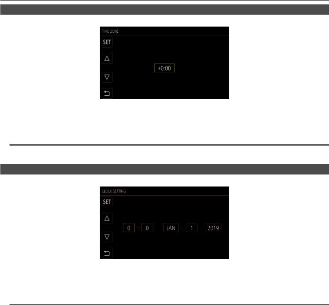
[TIME ZONE]
Set the time difference from the Greenwich Mean Time.
1 Set the time difference.
2Select [SET].
Once the setting for [TIME ZONE] is completed, the [CLOCK SETTING] screen is displayed.
@@NOTE
tt The setting for the date/time of the camera changes together with the time zone settings. tt This can also be set with the [OTHERS] menu → [CLOCK] → [TIME ZONE].
[CLOCK SETTING]
Set the year, month, date, and time.
1 Set the year, month, date, and time.
2Select [SET].
Once the setting is complete, the camera image screen is displayed on the LCD monitor.
@@NOTE
tt This can also be set with the [OTHERS] menu → [CLOCK] → [CLOCK SETTING].
– 16 –

Chapter 1 Overview — Use of the camera on a system
Use of the camera on a system
Parts other than the camera are optionally available. Use the following recommended parts.
Basic configuration devices
Equipment necessary for shooting with the camera, such as batteries, etc.
Part name |
Part No. |
Remark |
|
Super-directional electret stereo microphone |
AG MC200G |
“Mounting the external microphone” (page 36) |
|
(phantom +48V) |
|||
|
|
||
|
AG VBR59 (7.28 V, 5900 mAh, product compatible |
|
|
Battery |
to included battery) |
|
|
AG VBR89 (7.28 V, 8850 mAh) |
“Attaching and removing the battery” (page 32) |
||
|
AG VBR118 (7.28 V, 11800 mAh) |
|
|
|
VW VBD58 (7.2 V, 5800 mAh) |
|
|
|
AG BRD50 (Product compatible to included battery |
|
|
Battery charger |
charger) |
“Charging the battery” (page 30) |
|
|
AG B23 |
|
|
Memory card* |
Visit the support desk at the website* |
“Preparing the memory card” (page 41) |
*For the latest information not included in these Operating Instructions, refer to the support desk at the following website. https://pro-av.panasonic.net/
Expanded configuration devices
In addition to the basic components, a wireless module can be used.
Part name |
Part No. |
Remark |
Wireless module |
AJ WM50 |
“For the wireless module” (page 170) |
For details on wireless modules that can be connected, refer to the support desk at the following website. https://pro-av.panasonic.net/
– 17 –

Chapter 1 Overview — What you can do with this camera
What you can do with this camera
This camera is an industrial 4K hand-held camera recorder equipped with a 1.0-inch sensor. ffEquipped with a high-sensitivity 1.0-inch MOS sensor for approximately 15.03 million effective pixels. Achieves F12 (at 59.94 Hz)/F13 (at 50 Hz) in the high-sensitivity mode.
ffThe UHD (3840×2160) 59.94p/50p signal can be recorded to the memory card with high image quality and high efficiency 10 quantizing bits.
ffEquipped with wide angle 24.5 mm (35 mm conversion value), approximately 32x zoom using the I.ZOOM function (approximately 24x zoom when recording in UHD), and hybrid optical image stabilizer (Hybrid O.I.S.).
ffEquipped with a LAN terminal that supports live streaming and wired control (Gigabit Ethernet), in addition to the input/output terminals (XLR input/SDI output) which are necessary for business use.
Recording to the memory card
Recording in following types is possible. ffUHD and FHD recording
(4:2:0 (10-bit) MOV recording (HEVC)/4:2:0 (8-bit) MOV recording/4:2:2 (10-bit) MOV recording) ffAVCHD recording
ffVariable frame rate recording
(Supports 120fps/100fps shooting at the FHD resolution) ffSimultaneous recording
ffRelay recording ffInterval recording ffBackground recording ffPre-recording
Linking to external devices
Connecting to monitor
A monitor can be connected to output images.
Video/audio cable* (<AV OUT> terminal)
HDMI cable
Monitor
BNC cable (<SDI OUT> terminal)
*Use a commercial video/audio cable (4-pole mini plug). Check the wire specifications of the 4-pole mini plug.
Audio (Left audio: White) |
|
Video (Yellow) |
|
Ground |
Audio (Right audio: Red) |
ffUse the double shielded cable supporting 4K/60P as the HDMI cable (optional). It is also recommended to use the Panasonic 4K/60P compatible HDMI cable.
ffFor the BNC cable (optional) connected to the <SDI OUT> terminal, prepare a double-shielded cable equivalent to 5C FB.
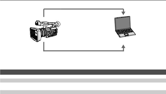
Card reader mode
Data (files) for performing nonlinear editing on a computer are transferred. ffThe camera supports USB 3.1 (GEN1).
– 18 –
Chapter 1 Overview — What you can do with this camera
Memory card*1
Computer
USB type C cable*2
*1 Memory cards are optionally available. They are not supplied with the camera. *2 A USB type C cable is not supplied with the camera.
Use a commercial USB-type C cable. Use of a cable no longer than 1.5 m is recommended. The camera does not offer a bus-powered function.
Connecting to the network
Wired LAN connection
Streaming from the camera is possible by using the <LAN> terminal.
Wireless LAN connection
The camera can be connected to the wireless LAN by connecting a wireless module compatible to the camera to the <USB2.0 HOST> terminal of camera.
The following operations can be performed from an iPad or Android terminal that has the CX ROP app installed. ffChecking camera status
ffCamera remote control (focus, zoom, image quality settings, recording control such as start/end recording, and time code/user bits settings) ffMenu Operations
ffStarting and stopping streaming (when the function is assigned to the USER button)
The camera supports the multi-camera function that a camera selected from up to eight cameras is controlled remotely from a single device.
For details of the wireless module supported by the camera and the operation of the CX ROP app, visit the support desk at the following website or refer to the online help for the app.
https://pro-av.panasonic.net/
– 19 –

Chapter 2 Description of Parts
This chapter describes the names, functions, and operations of parts on the camera.
Chapter 2 Description of Parts — Camera
Camera
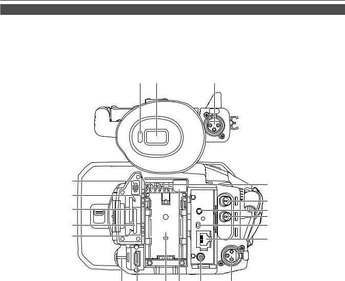
Left side
1 |
2 |
3 |
4 |
5 |
6 |
7 |
9
9
8
1 Eye cup
2Eyepiece
Do not leave the eyepiece pointed toward the sun. Doing so might damage the devices inside.
3<USB2.0 HOST> terminal
Can connect to wireless LAN when the wireless module (optional) compatible to camera is mounted.
4REC button (on the grip)
Starts or stops the recording.
Used for direct shooting in thumbnail mode.
5Power switch
Switches between power on/standby.
To turn on, set the power switch to < j > (ON). To set to standby, set the power switch to < h > (standby).
6Microphone cable clamp
Fixes the external microphone cable.
7Microphone holder mounting section
Mounts the supplied microphone holder with microphone holder screws.
8Tripod holes
Attaches the tripod. (bottom) ffMounting hole size
-- 1/4 20 UNC (screw length 5.5 mm or shorter) -- 3/8 16 UNC (screw length 5.5 mm or shorter)
9Accessory mounting holes
Attaches accessories.
The weight of the accessory should be no more than 2 k] including the mounting fixture. ffMounting hole size
-- Mounting screw size: M3 -- Mounting hole depth: 6 mm -- Mounting hole pitch: 25 mm
– 21 –
Chapter 2 Description of Parts — Camera
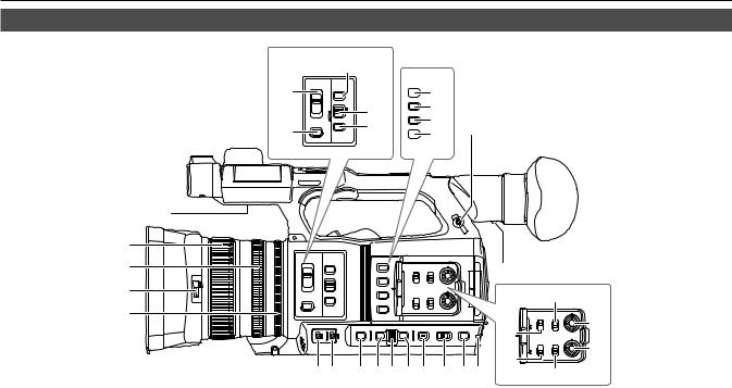
Right side
22
18
19
ND |
|
|
FILTER |
FOCUS |
|
|
ASSIST |
|
1/64 |
|
|
1/16 |
FOCUS |
|
1/4 |
||
A |
||
CLR |
M |
|
|
∞ |
|
|
PUSH AUTO |
|
IRIS |
|
20
21
O.I.S.  1 ZEBRA
2
WFM
3
A.IRIS LEVEL  4
4
23
24
25 7
26
|
6 |
|
|
|
1 |
|
|
|
|
2 |
5 |
|
|
|
3 |
|
|
31 |
|
4 |
|
|
CH1 |
CH 1 |
|
INPUT 1 |
SELECT |
29 |
|
|
|
LINE |
INT(L) |
|
|
27 |
MIC |
INPUT1 |
|
|
+48 V |
INPUT2 |
||
|
|
|
AUDIO |
|
|
INPUT 2 |
CH2 |
LEVEL |
|
|
|
SELECT |
30 |
|
|
|
LINE |
INT(R) |
|
|
|
MIC |
INPUT1 |
|
|
28 |
+48 V |
INPUT2 |
|
|
|
|
CH 2 |
8 |
9 |
10 11 12 13 14 |
15 |
16 17 |
32 |
1Focus ring
Manually focuses when the <FOCUS> switch is set to <M>.
2Zoom ring
Manually adjusts the zoom lens.
3Lens cover switching lever
Opens/closes the lens cover.
4Iris ring
Adjusts the lens iris manually when the manual iris is set with the <IRIS> button.
5Diopter adjustment lever
Adjusts the diopter scale so that the viewfinder screen can be viewed clearly.
6Built-in speaker
Outputs audio during playback.
Audio is not output from the built-in speaker when headphones are connected to the headphone terminal.
7Headphones terminal
Connects audio monitoring headphones.
8<GAIN> switch
Switches the brightness of the screen according to the lighting conditions under which you are shooting.
9<WHITE BAL> switch
Selects the method for adjustment of the white balance.
ff<PRST>: Adjusts the white balance to the preset value. [3200K], [5600K], and [VAR] toggle each time the <AWB> button is pressed. ff<A>/<B>: Selects when using the stored value for the adjustment of the white balance.
10<SHUTTER> button
Toggles the shutter mode.
11<MENU> button
Displays the menu. Pressing the <MENU> button while the menu is displayed closes the menu.
Press the button while the thumbnail screen is displayed to display the operation screen of the thumbnail menu, and clips can be deleted.
12Multidial
Moves, selects, and sets the menu while the menu is displayed.
Use the multidial to also operate thumbnails, select the multi manual function and select/set the various operation icons.
13<EXIT> button
Returns to one level higher when the menu is displayed. Pressing the <EXIT> button without confirming the setting value will not reflect the change in the setting.
14<DISP/MODE CHK> button
Displays/hides information other than the time counter, time stamp, zebra pattern, and marker.
Press and hold the button to display information about the settings of the various shooting functions and information such as a list of the functions assigned to the USER button. Each press of the button toggles the information page in order.
15<AUTO/MANUAL> switch
Selects the method to adjust the focus, gain, iris, white balance, and shutter speed at shooting. You can set the function to assign to <AUTO> in the [CAMERA] menu → [AUTO SW].
<AUTO>: Adjusts automatically. (Auto mode) <MANU>: Adjusts manually. (Manual mode)
16<SLOT SEL> button/<USER 5> button
Selects the card slot to record to or play back from. This is also used as the USER button (USER5).
– 22 –

Chapter 2 Description of Parts — Camera
17Rear tally lamp
Illuminates when the recording is started. Flashes when the battery level becomes low. Whether or not to illuminate the lamp can be set in the menu.
18<ND FILTER> switch
Selects the ND filter to suit the illumination of the subject. <CLR>: Does not use the ND filter.
<1/4>: Reduces the amount of light entering the MOS sensor to 1/4. <1/16>: Reduces the amount of light entering the MOS sensor to 1/16. <1/64>: Reduces the amount of light entering the MOS sensor to 1/64.
19<IRIS> button
Selects the method for adjustment of the lens iris.
20<FOCUS> switch
Select the focus function.
<A>: Changes to the auto focus mode. The auto focus mode adjusts the focus automatically. <M>: Changes to the manual focus mode. Control the focus ring manually to adjust the focus. <c>: Changes to the manual focus mode after the focus distance is set to infinity.
The <FOCUS> switch is a spring switch. The switch returns to the <M> position even when pushed towards the <c> side.
21<PUSH AUTO> button
Performs automatic focusing while pressing the button during manual focus mode.
22<FOCUS ASSIST> button
Enables/disables the focus assist function which is set in the [VIDEO OUT/LCD/VF] menu → [FOCUS ASSIST] → [FOCUS ASSIST SW].
23<O.I.S.>/<USER 1> button
Enables/disables the optical image stabilizer function. This is also used as the USER button (USER1).
24<ZEBRA>/<USER 2> button
Displays/hides zebra patterns.
This is also used as the USER button (USER2).
25<WFM>/<USER 3> button
Displays/hides the waveform monitor displayed on the LCD monitor. This is also used as the USER button (USER3).
26<A.IRIS.LEVEL>/<USER 4> button
Enables/disables the auto iris level function.
Set the target value of the auto iris level in the [SCENE FILE] menu → [A.IRIS LEVEL EFFECT]. This is also used as the USER button (USER4).
27<INPUT1> switch
Switches audio input signals connected to the <AUDIO INPUT 1> terminal. <LINE>: Select when audio equipment is connected by the line input. <MIC>: Select when the external microphone is connected.
<+48V>: Select when the external microphone is connected and the microphone needs a power supply.
28<INPUT2> switch
Switches audio input signals connected to the <AUDIO INPUT 2> terminal. <LINE>: Select when audio equipment is connected by the line input. <MIC>: Select when the external microphone is connected.
<+48V>: Select when the external microphone is connected and the microphone needs a power supply.
29<AUDIO LEVEL CH1> dial
Adjust the recording level of audio channel 1.
30<AUDIO LEVEL CH2> dial
Adjust the recording level of audio channel 2.
31<CH1 SELECT> switch
Selects the audio to be recorded on audio channel 1. <INT(L)>: Records the left audio of the built-in microphone.
<INPUT1>: Records input signals from the <AUDIO INPUT 1> terminal. <INPUT2>: Records input signals from the <AUDIO INPUT 2> terminal.
32<CH2 SELECT> switch
Selects the audio to be recorded on audio channel 2. <INT(R)>: Records the right audio of the built-in microphone.
<INPUT1>: Records input signals from the <AUDIO INPUT 1> terminal. <INPUT2>: Records input signals from the <AUDIO INPUT 2> terminal.
– 23 –
Chapter 2 Description of Parts — Camera
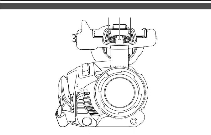
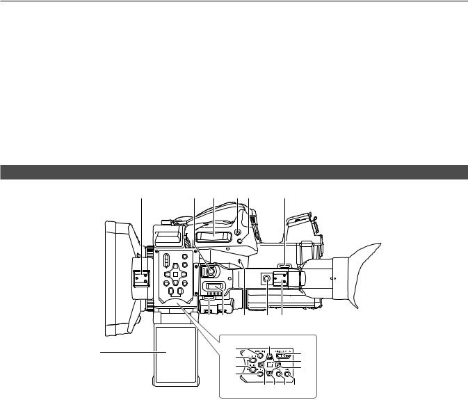
Front side
1 |
2 |
1 |
3 |
4 |
1Built-in microphone
This is the built-in stereo microphone <L>/<R>.
2Front tally lamp
Illuminates when the recording is started. Flashes when the battery level becomes low. Whether or not to illuminate the lamp can be set in the menu.
3Fan outlet
Fan outlet for cooling fan. Do not block this while the camera is being used.
4<AWB>/<USER 7> button
Adjusts the white balance. Press it for two seconds or more to adjust the white balance and then black balance. This is also used as the USER button (USER7).
– 24 –
Chapter 2 Description of Parts — Camera
Rear side
Following terminals, card slots, and card access lamps are inside each cover. ff<USB3.0 DEVICE> terminal
ff<AV OUT> terminal ff<REMOTE> terminal ff<LAN> terminal ff<HDMI> terminal ff<DC IN 12V> terminal
12 |
13 |
14 |
1 |
|
|
|
|
6 |
|
|
|
|
|
|
2 |
|
|
|
|
7 |
|
|
|
|
|
|
3 |
|
|
|
|
8 |
|
|
|
|
|
9 |
4 |
|
|
|
|
10 |
5 |
|
|
|
|
11 |
|
|
|
|
|
|
15 |
16 |
17 |
18 |
19 |
20 |
1<USB3.0 DEVICE> terminal
Connect to a computer with the USB type C cable to transfer data.
2Card 1 access lamp
Indicates the access status for recording and playback of the memory card inserted in card slot 1. Whether or not to illuminate the lamp can be set in the menu.
3Card slot 1
A slot for the memory card.
4Card slot 2
A slot for the memory card.
5Card 2 access lamp
Indicates the access status for recording and playback of the memory card inserted in card slot 2. Whether or not to illuminate the lamp can be set in the menu.
6Fan inlet
Fan inlet for cooling fan. Do not block this while the camera is being used.
7<SDI OUT> terminal
A terminal to output SDI signal by connecting a monitor, etc.
8<AV OUT> terminal
This is the output terminal for the video and audio of an external monitor.
9<TC IN/OUT> terminal
Connects to an external equipment and output/input a time code.
Inputs the standard time code when locking the time code with an external equipment. Input and output are set in the [RECORDING] menu → [TC/UB] → [TC IN/OUT SEL].
10<REMOTE> terminal
Connects the remote control unit (optional) to control some functions remotely.
11<LAN> terminal
Connects the LAN cable.
12Eye sensor
Screen is displayed on the viewfinder when an eye is brought close.
13Viewfinder
– 25 –
Chapter 2 Description of Parts — Camera
14<AUDIO INPUT 1> terminal (XLR, 3-pin)
Connects an audio equipment or an external microphone.
15Rear tally lamp
Illuminates when the recording is started. Flashes when the battery level becomes low. Whether or not to illuminate the lamp can be set in the menu.
16<HDMI> terminal
A terminal to output video signal by connecting a monitor, etc.
17Battery mounting section
Mounts a battery.
18Battery release button
Used when removing the battery from the camera.
19<DC IN 12V> terminal
Connects the supplied AC adaptor and supplies an external power.
20<AUDIO INPUT 2> terminal (XLR, 3-pin)
Connects an audio equipment or an external microphone.
Top side
2 |
3 |
4 |
5 |
6 |
|
7 |
|
7 |
8 |
|
9 |
10 |
11 |
|
|
|
12 |
|
19 |
|
1 |
|
|
|
|
16 |
|
|
|
13 |
|
|
||
|
|
|
|
|
17 |
|
|
|
|
14 |
|
|
|
|
|
|
|
|
18 |
|
|
|
|
15 |
|
|
|
|
|
|
|
|
20 21 22 23 |
|
1 LCD monitor
2Light shoe
Attaches the video light, etc.
3REC button (on the handle)
Starts or stops the recording. This includes hold mechanism.
4Zoom lever (on the grip)
Adjusts the zoom of an image. <T>: Zooms in the image. <W>: Zooms out the image.
5<IRIS>/<USER 6> button
Selects the method for adjustment of the lens iris. This is also used as the USER button (USER6).
6<REC CHECK> button
Press this button while recording is suspended to play back the last three seconds of video or audio of the clip that was just shot.
7Shoulder strap mounting section
Mounts the supplied shoulder strap. (page 34)
8Zoom lever (on the handle)
Adjust the zoom of an image. <T>: Zooms in the image. <W>: Zooms out the image.
9Focal plane index < >
>
Indicates the focal plane of the MOS sensor. It provides a reference for measuring the accurate focal distance from the subject.
10Handle mounting holes
Mounts the handle. ffMounting hole size
-- 1/4 20 UNC (screw length 5.5 mm or shorter)
11Accessory shoe
Attaches the video light.
– 26 –

Chapter 2 Description of Parts — Camera
12<THUMBNAIL> button
Press this button to display the thumbnail screen on the LCD monitor and viewfinder. Press it again to return to the regular display.
13<COUNTER> button
Switches the display item of the counter.
14<RESET> button
Resets the time counter or clears the input value in the keyboard screen.
15<MENU> button
Displays the menu. Pressing the <MENU> button while the menu is displayed closes the menu. Press it while the thumbnail is displayed to display the operation screen of the thumbnail menu, and clips can be deleted.
16<AUDIO MON/ADV> button
Adjusts the volume of the monitor audio during playback, recording, and recording standby.
<+>: Increases the volume of the monitor audio. When pressing during pause, frame-by-frame play is performed. <−>: Decreases the volume of the monitor audio. When pressing during pause, frame-by-frame rewind is performed.
17<SET> button
Performs operations of the settings menu and thumbnails.
18<)> button
Performs operations of the settings menu and thumbnails.
Press this button during playback to perform fast-forward playback.
Press this button while playback is paused to skip to the beginning of the next clip.
19<=/&> button
Performs operations of the settings menu and thumbnails. Press this button to view playback images.
Press this button during playback to pause playback.
Press this button to resume playback during a pause, fast-forward playback, or fast-reverse playback.
20<%> button
Performs operations of the settings menu and thumbnails. Press this button during playback to fast-reverse playback.
Press this button while playback is paused to skip to the beginning of the clip.
21<(> button
Performs operations of the settings menu and thumbnails. Press this button to stop playback when a clip is playing.
22<EXIT> button
Returns to one level higher when the menu is displayed. Pressing the <EXIT> button without confirming the setting value will not reflect the change in the setting.
23<BARS> button
Switches on/off the color bar. The color bar is interlocked with the test tone (1 kHz).
– 27 –
Chapter 2 Description of Parts — Basic operation
Basic operation
Multidial operation
Operate the multidial on the camera by turning it in vertical direction or pushing it. ffTurning the multidial in vertical direction will move the cursor.
The cursor can also be moved by pressing the <%> button, <(> button, <)> button, and <=/&> button. ffPressing the multidial will select or confirm the item with cursor.
Selection and confirmation are also available by pressing the <SET> button.
ffValues of the menu or the pages of the thumbnail screen can be changed continuously by pressing and turning the multidial vertically to fix the setting.
Values of the menu or the pages of the thumbnail screen can be changed continuously even by pressing and holding the <%> button, <(> button, <)> button, and <=/&> button.
@@NOTE
tt For details about operating the menu, refer to “When operating with the multidial” (page 62).
Touch operation of the LCD monitor
The LCD monitor can be operated by directly touching with a finger.
Do not touch the LCD monitor with a pointed hard object such as a ball point pen.
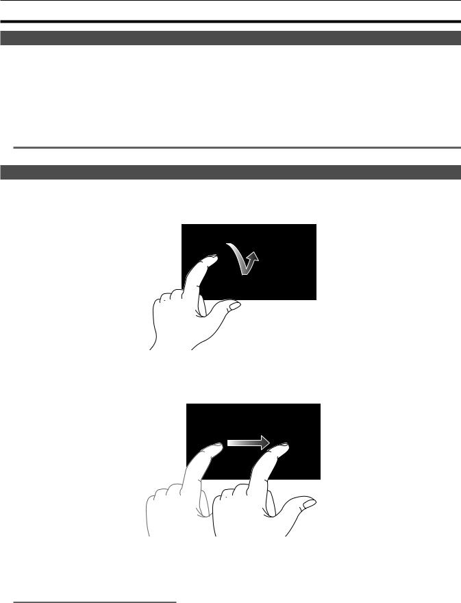
rr Touching
An operation to press and release the LCD monitor. An item or icon can be selected, or an item can be executed. ffTo select an icon, touch the center of the icon.
ffIt will not operate while touching a different location of the LCD monitor.
rr Sliding
An operation to move a finger while touching the LCD monitor. Playback operation such as the skip playback or direct playback, etc. can be performed.
rr Touching and holding
An operation to keep on pressing, then releasing the LCD monitor. Values of the menu or the pages of the thumbnail screen can be changed continuously.
@@NOTE
tt For details about operating the menu, refer to “When operating by touching the LCD monitor” (page 63).
– 28 –

Chapter 3 Preparation
Before you use the camera, mount the battery following the procedures in this chapter. The mounting of accessories is also described in this chapter.
Chapter 3 Preparation — Power supply
Power supply
A battery or the supplied AC adaptor can be used as the power supply for the camera. ffThe camera is compatible to following batteries. (As of February 2019)
-- AG VBR59 (supplied/optional, supports quick charging) -- AG VBR89 (optional, supports quick charging)
-- AG VBR118 (optional, supports quick charging) -- VW VBD58 (optional)
Charging the battery
The battery is not charged at the time of purchase. Fully charge the battery in the battery charger before using the battery. It is recommended that you have one extra battery.
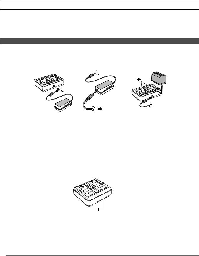
ffIt is recommended to perform charging of the batter in a location with ambient temperature of 10 °C to 30 °C (same for the battery temperature). ffThe supplied AC cable is dedicated for this camera. Do not use with any other device. Also, do not use AC cable from other device on this camera. ffThe supplied battery charger can simultaneously charge two batteries. Also, it is compatible with the quick charge battery.
To the power outlet
Fig. 1 |
Fig. 2 |
Fig. 3 |
1 Connect the DC plug of the AC adaptor to the <DC IN 12V> terminal of the battery charger. (Fig. 1)
2Connect the AC cable to the AC adaptor. (Fig. 2) ffInsert the AC cable all the way in until it stops.
3 Connect the power plug to the power outlet. (Fig. 2)
4 Mount the battery to the battery charger. (Fig. 3)
The charging lamp of the side the mounted battery will illuminate, and the charging will start. ffPlace the battery horizontally along the mark, and slide it.
ffOnce the charging is completed, the <CHARGE1>/<CHARGE2> lamp (charging lamp) will turn off. Slide the battery and remove it.
rr Display of the <CHARGE1>/<CHARGE2> lamp
<CHARGE1>/<CHARGE2> lamp
The <CHARGE1>/<CHARGE2> lamp (charging lamp) of the supplied battery charger indicates the charging status as follows.
Display of the <CHARGE1>/<CHARGE2> lamp |
Charging status |
Green (illuminated) |
Quick charging |
Orange (illuminated) |
Normal charging |
Orange (flashing) |
Stopped charging due to an error |
Off |
Charging is completed or the battery is not mounted |
@@NOTE
tt The battery charger will determine the status of the battery after the battery is mounted. Therefore, it may take some time until the charging lamp is to illuminate. Mount the battery again if the charging lamp does not illuminate after ten seconds or longer has elapsed.
tt When two quick charging compatible batteries are mounted, the quick charging on the <CHARGE1> side will take priority, and the charging on the <CHARGE2> side will be normal charging. Once the charging of the <CHARGE1> side proceeds, the charging on the <CHARGE2> side will switch to quick charging.
Also, depending on the charging status of the battery, the indicator on the battery that is mounted on the <CHARGE2> side may turn off.
tt The battery charger will perform optimal charging after determining the status of the battery. Once the charging is started, the indicator for quick charging compatible battery will flash. Also, if it is charging on both <CHARGE1> side and <CHARGE2> side, charging of both batteries will stop when either one of the battery is mounted/removed, or replaced. It will start the charging again after determining the status of the batteries.
tt Mount the battery to be charged prioritized on the <CHARGE1> side when charging.
– 30 –
 Loading...