


 Loading...
|
|
|
|
|
|
|
|
|
|
|
|
|
|
|
|
|
|
|
|
|
|
|
|
|
|
This product is eligible for the AVCCAM |
|
|
|
|
|
|
|
|
|
|
|
3 Year Warranty Repair Program. For |
Operating Instructions |
||
|
|
details, see page 5. |
|||
|
|
|
|
|
|
|
|
|
|
||
|
|
|
|
|
|
|
|
|
Memory Card Camera-Recorder |
||
Model No. AG-HMC151E
Before operating this product, please read the instructions carefully and save this manual for future use.
S0808K0 -M |
ENGLISH |
VQT1V34 (E)
 Reference Menu Displays Editing Playback Shooting Preparation Description Before use of parts
Read this first!
 indicates safety information.
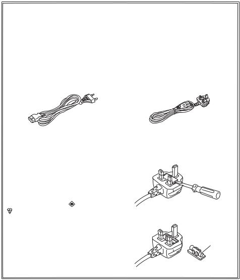
Caution for AC Mains Lead
FOR YOUR SAFETY PLEASE READ THE FOLLOWING TEXT CAREFULLY.
This product is equipped with 2 types of AC mains cable. One is for continental Europe, etc. and the other one is only for U.K.
Appropriate mains cable must be used in each local area, since the other type of mains cable is not suitable.
FOR CONTINENTAL EUROPE, ETC. |
FOR U.K. ONLY |
Not to be used in the U.K. |
|
|
|
FOR U.K. ONLY |
|
How to replace the fuse |
This appliance is supplied with a moulded |
1. Open the fuse compartment with a |
|
three pin mains plug for your safety and |
screwdriver. |
|
convenience. |
|
|
A 5 amp fuse is fitted in this plug. |
|
|
Should the fuse need to be replaced please |
|
|
ensure that the replacement fuse has a rating |
|
|
of 5 amps and that it is approved by ASTA or |
|
|
BSI to BS1362. |
|
|
Check for the ASTA mark |
or the BSI mark |
|
on the body of the fuse. |
2. Replace the fuse |
|
If the plug contains a removable fuse cover |
||
|
||
you must ensure that it is refitted when the |
|
|
fuse is replaced. |
Fuse |
|
If you lose the fuse cover the plug must |
||
|
||
not be used until a replacement cover is |
|
|
obtained. |
|
|
A replacement fuse cover can be purchased |
|
|
from your local Panasonic Dealer. |
|
2
 DO NOT REMOVE PANEL COVERS BY UNSCREWING THEM.
To reduce the risk of electric shock, do not remove cover. No user serviceable parts inside. Refer servicing to qualified service personnel.
WARNING:
•TO REDUCE THE RISK OF FIRE OR SHOCK HAZARD, DO NOT EXPOSE THIS EQUIPMENT TO RAIN OR MOISTURE.
•TO REDUCE THE RISK OF FIRE OR SHOCK HAZARD, KEEP THIS EQUIPMENT AWAY FROM ALL LIQUIDS. USE AND STORE ONLY IN LOCATIONS WHICH
ARE NOT EXPOSED TO THE RISK OF DRIPPING OR SPLASHING LIQUIDS, AND DO NOT PLACE ANY LIQUID CONTAINERS ON TOP OF THE EQUIPMENT.
WARNING:
Always keep memory cards or accessories (coin battery, microphone holder screws, microphone holder adapter, ferrite cores, binders, INPUT terminal covers) out of the reach of babies and small children.
CAUTION:
TO REDUCE THE RISK OF FIRE OR SHOCK HAZARD AND ANNOYING INTERFERENCE, USE THE RECOMMENDED ACCESSORIES ONLY.
CAUTION:
In order to maintain adequate ventilation, do not install or place this unit in a bookcase, built-in cabinet or any other confined space. To prevent risk of electric shock or fire hazard due to overheating, ensure that curtains and any other materials do not obstruct the ventilation.
CAUTION:
Do not lift the unit by its handle while the tripod is attached. When the tripod is attached, its weight will also affect the unit’s handle, possibly causing the handle to break and hurting the user. To carry the unit while the tripod is attached, take hold of the tripod.
CAUTION:
Danger of explosion or fire if battery is mistreated.
For Battery Pack
•Replace only with same or specified type.
•Do not disassemble or dispose of in fire.
•Do not store in temperatures over 60°C (140°F).
•Do not leave the battery in an automobile exposed to direct sunlight for a long period of time with doors and windows closed.
•Use specified charger.
For Battery of Remote Controller
•Replace battery with part No. CR2025 only.
•Do not recharge the battery.
•Do not disassemble or dispose of in fire.
•Do not store in temperatures over 60°C (140°F).
indicates safety information.
Camera-Recorder
The rating plate is on the underside of the viewfinder.
AC Adapter
The rating plate is on the underside of the AC Adapter.
Disconnect the AC mains plug from the AC mains socket when not in use.
CAUTION:
THE MAINS PLUG OF THE POWER SUPPLY CORD SHALL REMAIN READILY OPERABLE. THE AC RECEPTACLE (MAINS SOCKET OUTLET) SHALL BE INSTALLED NEAR THE EQUIPMENT AND SHALL BE EASILY ACCESSIBLE.
TO COMPLETELY DISCONNECT THIS EQUIPMENT FROM THE AC MAINS, DISCONNECT THE POWER CORD PLUG FROM THE AC RECEPTACLE.
CAUTION:
Do not jar, swing, or shake the unit by its handle while the conversion lens or another accessory is attached.
Due to the added weight of the conversion lens, any strong jolt to the handle may damage the unit or result in personal injury.
CAUTION:
EXCESSIVE SOUND PRESSURE FROM EARPHONS AND HEADPHONES CAN CAUSE HEARING LOSS.
CAUTION:
Do not leave the unit in direct contact with the skin for long periods of time when in use.
Low temperature burn injuries may be suffered if the high temperature parts of this unit are
in direct contact with the skin for long periods of time.
When using the equipment for long periods of time, make use of the tripod.
3

Operating precaution
Operation near any appliance which generates strong magnetic fields may give rise to noise in the video and audio signals. If this should be the case, deal with the situation by, for instance, moving the source of the magnetic fields away from the unit before operation.
IMPORTANT
“Unauthorized recording of copyrighted television programs, video tapes and other materials may infringe the right of copyright owners and be contrary to copyright laws.”
Recommendation for Use of Genuine Panasonic Battery (Rechargeable Battery)
Thank you for using a Panasonic product.
It has been found that counterfeit battery packs which look very similar to the genuine product are made available to purchase in some markets. Some of these battery packs are not adequately protected with internal protection to meet the requirements of appropriate safety standards. There is a possibility that these battery packs may lead to fire or explosion. Please be advised that we are not
liable for any accident or failure occurring as a result of use of a counterfeit battery pack. To ensure that safe products are used we would recommend that a genuine Panasonic battery pack is used.
•Be aware that many batteries sold at extremely cheap prices or in situations where it is difficult to verify the actual products before purchase have proven to be counterfeit.
■Batteries that may be used with this product (Correct as of August 2008)
Panasonic VW-VBG260 and VW-VBG6 batteries may be used with this product.
The VW-VBG260 and VW-VBG6 batteries contain a function to enable verification as to whether they may be safely used with this product.
4

EU
To remove the battery
Main Power Battery
(Refer to page 20 for the detail.)
Press the battery release button.
Battery release button
Remote Control Battery
1) Push the catch in the direction shown by arrow  to remove the holder.
2)Remove the button-type battery from the battery holder.
AVCCAM 3 Year Warranty Repair Program*1
Thank you for purchasing this Panasonic AVCCAM device.
Register as a user for this device to receive a special service warranty up to three years of free warranty repairs.
Customers who register as users on the website will receive an extended warranty repair valid for up to three years.
|
|
|
|
1st year |
|
2nd year |
|
3rd year |
|
|
AVCCAM device*2 |
|
Basic warranty*3 |
|
Extended warranty repair*4 |
||
|
|
|
|
|
|
|
|
|
|
|
*1: Please note that this extended warranty is not available in some countries/regions. *2: Not all models eligible for extended warranty coverage. |
||||||
|
|
*3: The basic warranty period may vary depending on the country/region. *4: Not all repair work is covered by this extended warranty. |
||||||
|
|
|
|
|
Free 3 years of Warranty Repairs |
|||
|
|
|
|
|
Make sure to save the “Registration Notice” e-mail |
|
||
Purchase |
Register online |
“Registration Notice” |
during the warranty period. |
|
||||
|
|
|
|
|||||
AVCCAM product |
within 1 month |
|
e-mail sent |
|
|
|
|
|
Details about user registration and the extended warranty:  http://panasonic.biz/sav/pass_e
5

Contents
Read this first! ................................................ |
2 |
Recommendation for Use of Genuine |
|
Panasonic Battery |
|
(Rechargeable Battery) .......................... |
4 |
Outline of operations ..................................... |
8 |
Please read before use .................................. |
9 |
SD Memory Cards compatible with this product..... |
9 |
(SD speed class 4) ........................ |
10 |
Before use |
|
Precaution for use........................................ |
11 |
Accessories .................................................. |
14 |
Optional accessories ................................... |
14 |
Description of parts |
|
Description of parts...................................... |
15 |
Right side and rear side .................................. |
15 |
Left side........................................................... |
16 |
Terminals and mounting parts ......................... |
17 |
Remote control ................................................ |
18 |
Preparation |
|
Recharging the battery ................................ |
18 |
Recharging ...................................................... |
18 |
Power sources.............................................. |
20 |
Using the battery ............................................. |
20 |
Using the AC adapter ...................................... |
20 |
Adjusting the hand strap ............................. |
21 |
Attaching the shoulder strap....................... |
21 |
Detaching and attaching the lens hood ..... |
21 |
The remote control....................................... |
22 |
Insert the battery ............................................. |
22 |
Remote control usable range .......................... |
22 |
Turn on/off the camera................................. |
22 |
Standby mode............................................... |
23 |
Tally lamp ...................................................... |
23 |
Viewfinder ..................................................... |
24 |
Using the viewfinder ........................................ |
24 |
Using the LCD ................................................. |
25 |
Emphasizing outlines ...................................... |
25 |
Adjusting the screen display............................ |
26 |
Changing backlight brightness ........................ |
27 |
Reversing image display ................................. |
27 |
Setting the calendar ..................................... |
28 |
Shooting |
|
Basic shooting operations .......................... |
30 |
Preparing for recording.................................... |
30 |
Shooting in auto mode .................................... |
30 |
Checking photos taken (REC CHECK) ........... |
31 |
SD Memory Card access lamp........................ |
31 |
Formatting SD Memory Cards......................... |
32 |
SD Memory Card recording times ................... |
32 |
Removing SD Memory Card ........................... |
33 |
Protecting SD Memory Cards.......................... |
33 |
Repairing SD Memory Cards .......................... |
33 |
Using the zoom function.............................. |
34 |
Digital zoom function ....................................... |
34 |
Shooting in progressive mode.................... |
35 |
Shooting in manual mode............................ |
36 |
Switching to manual mode ............................. |
36 |
Manual focusing ............................................. |
36 |
Using focus assist ........................................... |
37 |
Iris adjustments ............................................... |
37 |
Adjusting the gain............................................ |
38 |
Light intensity adjustments .............................. |
38 |
Adjusting the white balance............................. |
38 |
Shooting techniques for different targets.. |
41 |
Low angle recording ........................................ |
41 |
Self-portrait shooting ...................................... |
41 |
Zebra pattern .................................................. |
41 |
Marker ............................................................. |
42 |
Checking and displaying shooting status ........ |
42 |
PRE REC ........................................................ |
42 |
Optical Image Stabilizer .................................. |
43 |
Adding effects to images ................................. |
43 |
Using the USER buttons ................................ |
43 |
Backlight compensation .................................. |
43 |
Color bars........................................................ |
43 |
Wave form monitor function............................. |
44 |
Adjusting the volume while shooting ............... |
44 |
Shot mark function .......................................... |
45 |
Index recording................................................ |
45 |
Time stamp function ........................................ |
45 |
LAST CLIP function ......................................... |
45 |
Adjusting the shutter speed........................ |
46 |
Synchro scan................................................... |
47 |
Switching Audio Input.................................. |
48 |
Using the built-in microphone.......................... |
48 |
Using an external microphone and audio |
|
equipment.................................................... |
48 |
Adjusting the recording level ........................... |
49 |
Using scene files .......................................... |
50 |
Changing scene file settings ........................... |
50 |
Saving scene files and other settings on SD |
|
Memory Cards....................................... |
52 |
Clip metadata................................................ |
53 |
Uploading the metadata (META DATA) ........... |
54 |
Selecting the USER CLIP NAME |
|
recording method ........................................ |
54 |
Using the Counter ........................................ |
55 |
Counter display ............................................... |
55 |
TC preset mode............................................... |
55 |
Charging the built-in battery/ |
|
Setting the time code ........................... |
56 |
Recharging the built-in battery ........................ |
56 |
Setting the time code....................................... |
56 |
Specifying the time code (TC PRESET).......... |
56 |
Setting user information .................................. |
58 |
6

Playback |
|
Basic playback operations .......................... |
59 |
Thumbnail screen......................................... |
60 |
Basic thumbnail screen operations ................. |
60 |
Adding shot marks to clips .............................. |
62 |
Direct shooting functions ................................. |
62 |
Playback settings (PLAY SETUP)................ |
63 |
Set playback format (PB FORMAT)................. |
63 |
Repeat playback (REPEAT PLAY) .................. |
63 |
Resume playback (RESUME PLAY) ............... |
64 |
Set skip method (SKIP MODE) ....................... |
64 |
Thumbnail operations.................................. |
65 |
Selecting the thumbnail display method |
|
(THUMBNAIL SETUP) ................................ |
65 |
Deleting and protecting clips (OPERATION)... |
66 |
Format card and check clip and |
|
card information (CARD FUNCTIONS) ....... |
67 |
Useful playback functions........................... |
69 |
Fast forward/rewind......................................... |
69 |
Next/previous clip ............................................ |
69 |
Frame-by-frame playback ............................... |
70 |
Adjust volume.................................................. |
70 |
Viewing images on a television ....................... |
70 |
Checking the date and time............................. |
70 |
Editing |
|
Connecting external units ........................... |
71 |
Headphones .................................................... |
71 |
External microphone ....................................... |
71 |
Computer (non-linear editing/file transfer)....... |
72 |
Video deck (Dubbing)...................................... |
72 |
TV/Monitor....................................................... |
73 |
Nonlinear editing (PC mode) ....................... |
75 |
Menu |
|
Using the setup menus................................ |
82 |
Using the menus ............................................. |
82 |
Initializing the menu settings ........................... |
83 |
Setup menu structure .................................. |
84 |
Camera mode menu........................................ |
84 |
Playback mode menu...................................... |
85 |
Setup menu list............................................. |
86 |
SCENE FILE screen........................................ |
86 |
SW MODE screen ........................................... |
88 |
AUTO SW screen............................................ |
90 |
RECORDING SETUP screen.......................... |
91 |
TC/UB SETUP screen..................................... |
92 |
AV OUT SETUP screen................................... |
93 |
DISPLAY SETUP screen................................. |
94 |
CARD FUNCTIONS screen ............................ |
96 |
USER FILE screen .......................................... |
96 |
META DATA screen ......................................... |
96 |
PLAY SETUP screen....................................... |
97 |
THUMBNAIL SETUP screen ........................... |
97 |
OPERATION screen........................................ |
98 |
OTHER FUNCTIONS screen .......................... |
98 |
Reference |
|
Before calling for service........................... |
100 |
Operating precautions ............................... |
104 |
Updating the driver in the camera ............ |
106 |
Cleaning ...................................................... |
106 |
Storage Precautions................................... |
107 |
Recording format........................................ |
108 |
How to handle data recorded on |
|
SD Memory Card................................. |
109 |
Specifications ............................................. |
110 |
Displays |
|
Screen displays ............................................ |
76 |
Regular displays.............................................. |
76 |
Main warning displays ..................................... |
79 |
Setting the DISPLAY items.............................. |
81 |
7

Outline of operations
This camera-recorder is compatible with the AVCHD standard, and uses low-cost and easily-available SD/SDHC Memory Cards as recording media.
The unit enables high-quality picture recording of close to broadcasting standard, as well as highly creative video production.
Television/Video device/Monitor
|
|
|
|
|
|
|
|
|
|
|
|
|
HDMI cable |
|
|
|
|
Component video |
|
||||||
|
|
|
|
cable |
|
|||||||
|
|
|
|
|
|
|
|
|||||
|
|
|
|
|
|
|
|
|
|
|
|
|
|
|
|
|
|
|
|
|
|
|
|
|
|
|
|
|
Video cable |
|
|
|
|
|
||||
|
|
|
|
|
|
|
|
|||||
|
|
|
|
|
||||||||
|
|
|
|
|
|
|
|
|
|
|
|
|
SD/SDHC
Memory Card
Recording to and playback from SD/SDHC
1 Memory Cards (Pages 30, 59)
SD/SDHC Memory Card
LOCK
32
•Images can be recorded in HD (high definition).
Please see page 109 for details on the handling of recorded data.
•A set number of user files can be recorded to and read from the SD Memory Card. (Page 52)
PC mode 2 (Page 75)
LOCK
32
Computer
USB2.0
Send data (files) to your computer for non-linear editing, etc.
8

Please read before use
SD Memory Cards compatible with this product
It is recommended that you use SD Memory Cards or SDHC Memory Cards of SD speed class 2 or above, or the following Panasonic SD Memory Cards (correct as of August 2008).
Speed class 4 or above is required for recording in PH mode or HA mode.
Card type |
Recording capacity |
Recording/playback |
Saving/reading of scene files and |
|
user files, reading of metadata |
||||
|
|
|
||
|
|
|
|
|
|
8 MB |
Cannot be used. |
|
|
|
16 MB |
|
||
|
|
|
||
|
32 MB |
Successful operation cannot be |
|
|
|
64 MB |
guaranteed. Recording may be |
|
|
SD Memory |
128 MB |
suddenly terminated with certain |
|
|
256 MB |
SD Memory Cards. |
|
||
Card |
|
|||
512 MB |
RP-SDV512 |
|
||
|
|
|||
|
1 GB |
RP-SDV01G |
|
|
|
RP-SDM01G |
|
||
|
|
|
||
|
2 GB |
RP-SDV02G |
|
|
|
RP-SDM02G |
|
||
|
|
Can be used. |
||
|
4 GB |
RP-SDV04G |
||
|
|
|||
|
RP-SDM04G |
|
||
|
|
|
||
|
6 GB |
RP-SDM06G |
|
|
|
8 GB |
RP-SDV08G |
|
|
|
RP-SDM08G |
|
||
SDHC Memory |
|
|
||
12 GB |
RP-SDM12G |
|
||
Card |
|
|||
|
RP-SDV16G |
|
||
|
|
|
||
|
16 GB |
RP-SDM16G |
|
|
|
|
AG-SDV016G |
|
|
|
32 GB |
RP-SDV32G |
|
|
|
AG-SDV032G |
|
||
|
|
|
•Please see our support page at the following website for the latest information not included in these operating instructions.
https://eww.pavc.panasonic.co.jp/pro-av/
•This product is compatible with SD Memory Cards formatted under the SD-standard FAT12 and FAT16 formats, and with SDHC Memory Cards formatted under the FAT32 format.
•Only SDHC Memory Cards may be used for capacities of 4 GB or greater.
•4 GB (or greater) memory cards without the SDHC logo are not based on the SD standard.
•Use this product to format the SD Memory Cards to be used. Formatting memory cards on computers or other devices may cause recording to take longer than normal, or may cause cards to become incompatible with this product. (Page 32) (Use this product to reformat any cards that have already been formatted on computers, etc.)
•Always install the relevant special adapter when using miniSD/miniSDHC cards with this product. (The product will not operate correctly if only the adapter is inserted – always insert a memory card into the adapter first.)
•MultiMediaCards cannot be used with this product.
(Continued on the next page)
9

Please read before use (continued)
This product (SDHC-compatible device) is compatible both with SD Memory Cards and with SDHC Memory Cards. SDHC Memory Cards may be used with SDHC Memory Card-compatible devices, but cannot be used with devices that are only compatible with SD Memory Cards. (Always check the relevant product’s operating instructions when using SDHC Memory Cards with other devices.)
SDHC-compatible device |
|
SD-compatible device |
||
|
|
|
|
|
Can be used |
Can be used |
Cannot be used |
Can be used |
|
|
|
|
|
|
|
|
|
|
|
|
|
|
|
|
SDHC Memory Card |
|
SD Memory Card |
|
SDHC Memory Card |
|
SD Memory Card |
||||||||
|
|
|
|
|
|
|
|
|
|
|
|
|
|
|


 (SD speed class 4)
This refers to a class 4 speed standard (SD speed class) for the continuous writing of data between SDcompatible devices and SD Memory Cards, as designated by the SD standards.
When the use of an SD speed class 4 card is recommended for SD-compatible products, this indicates that stable recording operation can be achieved when using SD Memory Cards of class 4 and above.
Cautions for usage
•Do not allow dirt, water, or other substances to come into contact with the connector part on the reverse of the card.
•Do not leave the card in the following places:
–In direct sunlight or in places of high humidity, e.g. close to heating equipment
–In highly humid or dusty locations
–In locations with high variations in temperature (condensation may appear on card)
–In places subject to static electricity or electromagnetic waves
•Store cards in bags or cases after use.
10
Precaution for use
Always take some trial shots before actual shooting.
•When shooting important events (such as weddings), always take some trial shots and check that the sound and images have been recorded properly before actual shooting.
Be sure to check and set the calendar and time zone.
•These settings affect the control and playback sequence of the recorded contents. Before making a recording, set and check the calendar and time zone. (Page 28)
Panasonic makes no guarantees for your recordings.
•Please understand that Panasonic makes no guarantees for your recordings in cases where images and/ or sound were not recorded as you intended due to problems with the camera-recorder or SD/SDHC Memory Cards.
Before use
Respect copyrights
•Copyright laws forbid the use of video and audio material you have recorded for any purpose other than your own personal enjoyment. Remember that restrictions apply to the shooting of certain material even if it is intended for private use.
Caution regarding laser beams
•The CCD may be damaged if it is subjected to light from a laser beam.
When using the camera-recorder in locations where laser irradiation equipment is used, be careful not to allow the laser beam to shine directly on the lens.
Media that can be used in this unit
• SD/SDHC Memory Cards can be used in this unit. For details, refer to page 9.
Mounting the camera-recorder on a tripod
•The tripod mounting hole is 5.5 mm deep. Do not force the tripod screw beyond this depth. You can damage the camera-recorder if you use any screw other than 1/4-20UNC.
Attach the tripod to the tripod hole.
For other usage notes, see page 104.
11

Precaution for use (continued)
 About this manual
Note concerning illustrations in these instructions
•Illustrations (camera-recorder, menu screens, etc.) in these operating instructions differ slightly from the actual camera-recorder.
References
• References are shown as (Page 00).
SD/SDHC Memory Cards
•Both SD Memory Cards and SDHC Memory Cards as referred to as “SD Memory Cards” in these operating instructions.
●The SDHC logo is a trademark.
●The miniSD logo is a trademark.
●“AVCHD” and the “AVCHD” logo are trademarks of Matsushita Electric Industrial Co., Ltd. and Sony Corporation.
●This product has been manufactured under license from Dolby Laboratories.
Dolby and the double-D symbol are trademarks of Dolby Laboratories.
●HDMI, the HDMI logo, and High-Definition Multimedia Interface are trademarks or registered trademarks of HDMI Licensing LLC.
●LEICA is a registered trademark of Leica Microsystems IR GmbH.
●DICOMAR is a registered trademark of Leica Camera AG.
●Microsoft®, Windows®, and Windows Vista® are either registered trademarks or trademarks of Microsoft Corporation in the United States and/or other countries.
●Screenshots are used in accordance with Microsoft Corporation guidelines.
●IBM and PC/AT are registered trademarks of International Business Machines Corporation.
●Intel® is a registered trademark or a trademark of Intel Corporation in the United States and/or other countries.
●Macintosh® is a trademark of Apple Inc., registered in the United States and other countries.
●Other model names, company names, and product names listed in these operating instructions are trademarks or registered trademarks of their respective companies.
●This product is licensed under the AVC Patent Portfolio License for the personal and noncommercial use of a consumer, and no license is granted or shall be implied for any use other than the personal uses detailed below.
–To encode video in compliance with the AVC standard (“AVC Video”)
–To decode AVC Video that was encoded by a consumer engaged in a personal and noncommercial activity
–To decode AVC Video that was obtained from a video provider licensed to provide AVC Video
•Additional information may be obtained from MPEG LA, LLC (http://www.mpegla.com).
–Separate license contracts must be obtained from MPEG LA where SD Memory Cards containing information recorded with this product are to be distributed to end users for commercial purposes. “End user” refers to persons or organizations handling such contents for personal use.
12

 What is AVCHD?
AVCHD is a standard for the recording and playback of highly detailed, high-definition video. Video is compressed in the MPEG-4 AVC/H.264 formats, and audio is recorded in Dolby Digital.
Before use
Information regarding compatibility of SDHC Memory Cards and recorded video
SDHC Memory Cards
●SDHC Memory Cards cannot be used with non-SDHC-compatible equipment.
●Ensure that all equipment is SDHC-compatible when using card with other devices. (Page 10)
Compatibility of recorded video
●Recorded video cannot be used with non-AVCHD-compatible equipment. For details, please see your product’s operating instructions.
●Recorded video cannot be played back on non-compatible (non-AVCHD-compatible) equipment.
●Playback may not always be possible on all AVCHD-compatible equipment. Please use this product for playback in such instances.
Older, non-AVCHD-compatible DVD recorder or DVD player, etc.
13
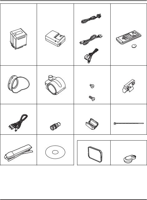
Accessories
Battery 1 |
AC Adapter |
AC power supply cords |
Wireless remote |
|
|
(For the U.K.) |
control and battery |
|
|
|
(CR2025) |
|
|
(For areas other than |
|
|
|
the U.K.) |
|
|
|
DC cord |
|
Eye cup |
Microphone holder |
Microphone holder |
Microphone holder |
|
|
screws |
adapter |
|
|
Length 6-mm (2) |
|
|
|
Length 12-mm (2) |
|
Component video |
PIN-BNC conversion |
Ferrite core (4) 2 |
Binder (4) |
cable |
plugs (3) |
|
|
Shoulder belt |
CD-ROM |
The following accessories are attached to the unit. |
|
|
|
Lens hood cap |
INPUT 1/2 terminal |
|
|
|
cover (2) |
1 For part numbers for the battery, see “Optional accessories”.
2 When using a USB connection cable (optional) or HDMI cable (optional), attach the ferrite cores at both ends of the cable. (Pages 72, 73)
• Please consult a retailer when purchasing additional accessories.
Optional accessories
•XLR microphone
AG-MC200G
•Battery
VW-VBG260 (7.2 V, 2640 mAh: equivalent to accessory battery) VW-VBG6 (7.2 V, 5800 mAh)
14

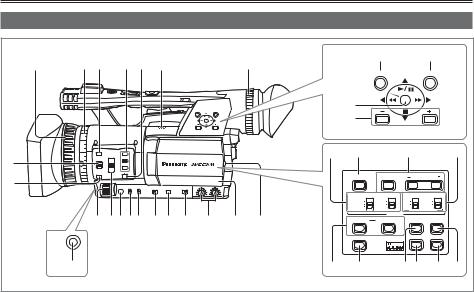
Description of parts |
|
|
|
|
|
|
|
|
|
|
|
|
Right side and rear side |
|
|
|
|
|
|
|
|
|
use |
|
|
|
|
|
|
|
|
|
|
|
|
|
|
|
1 |
2 |
5 |
|
7 |
9 |
11 |
|
|
|
|
Before |
|
POWER |
3 |
|
|
|
|
14 |
|
|
||||
ON |
4 |
|
6 |
8 |
10 |
12 |
|
|
|
|
|
|
OFF |
|
|
|
|
|
15 |
|
|||||
|
|
|
|
|
|
|
|
|
|
Description |
|
|
|
|
|
|
|
|
|
|
|
|
|
of parts |
|
|
|
|
|
|
|
|
|
|
|
|
1 |
|
|
|
|
|
|
|
|
|
|
|
|
2 |
|
|
|
|
|
|
|
|
|
PB |
|
|
|
|
|
|
|
|
13 |
|
17 |
|
19 |
21 |
23 |
|
|
|
|
|
|
|
16 |
18 |
20 |
22 |
|
|
||
|
|
|
|
|
|
|
|
|||||
1 |
POWER switch (Page 22) |
14 |
Viewfinder (Page 24) |
2 |
START/STOP button (Page 30) |
15 |
SD Memory Card slot cover (Page 30) |
3 |
REC CHECK button (Page 31) |
16 |
SCENE FILE dial (Page 50) |
4 |
Zoom button (Page 34) |
17 |
STAND BY button (Page 23) |
5 |
HANDLE ZOOM switch (Page 34) |
18 |
Mode button (Pages 30 and 59) |
6 |
REC selector switch (Page 41) |
19 |
Tally lamp (Rear) (Page 23) |
7 |
Handle zoom button (Page 34) |
20 |
Remote control sensor (Rear) (Page 22) |
8 |
Handle START/STOP button (Page 41) |
21 |
Mode lamp (Pages 30 and 59) |
9 |
Built-in stereo microphone (Page 48) |
22 |
Battery compartment (Page 20) |
10 |
White balance sensor (Page 40) |
23 |
Battery release button (Page 20) |
11Remote control sensor (Front) (Page 22)
12Tally lamp (Front) (Page 23)
13INPUT 1/2 (audio input) switches (Page 48)
15
Description of parts (continued)
Left side
1 |
2 |
3 |
4 |
5 |
6 |
|
|
|
7 |
|
22 |
23 |
|
||
|
|
|
MENU |
EXEC |
|
||||||||||
|
|
|
|
|
|
|
|
|
|
|
|
||||
|
|
|
|
|
|
|
|
|
|
|
PUSH-ENTER |
|
|
|
|
|
|
|
|
|
|
|
|
|
|
|
24 |
|
|
|
|
|
|
|
|
|
|
|
|
|
|
|
25 |
AUDIO MON/ADV |
|
||
|
|
|
|
|
|
|
|
|
|
|
|
|
|||
8 |
|
|
|
|
|
|
|
|
|
26 |
27 |
|
28 |
|
29 |
|
|
|
|
|
|
|
|
|
|
|
|
|
|
|
|
9 |
|
|
|
|
|
|
|
|
|
|
BARS |
SHUTTER |
SPEED SELECT |
|
|
|
|
|
|
|
|
|
|
|
|
|
|
|
|
|
|
|
|
|
|
|
|
|
|
|
|
|
CH1 SELECT |
CH2 SELECT |
INPUT 1 |
INPUT 2 |
|
|
|
|
|
|
|
|
|
|
|
|
INT(L) |
INT(R) |
ON |
ON |
|
|
|
|
|
|
|
|
|
|
|
|
INPUT1 |
INPUT2 |
OFF |
OFF |
|
|
|
|
|
|
|
|
|
|
|
|
INPUT2 |
|
MIC POWER +48V |
|
|
|
|
|
|
|
|
|
|
|
|
|
|
AUDIO |
|
||
|
|
11 |
12131415 |
16 |
17 |
18 |
19 |
20 |
21 |
|
|
|
|
||
|
|
COUNTER |
RESET/TC SET |
ZEBRA |
OIS |
|
|||||||||
|
|
|
|
|
|
|
|||||||||
|
AWB |
|
|
|
|
|
|
|
|
|
LCD |
|
EVF DTL |
WFM |
|
|
|
|
|
|
|
|
|
|
|
|
|
|
|
|
|
|
10 |
|
|
|
|
|
|
|
|
30 |
31 |
|
32 33 |
34 |
35 |
1Focus ring (Page 36)
2Zoom ring (Page 34)
If you don’t need the zoom ring pin, fit it into the provided pin holder (next page 4) so that you don’t lose it.
3FOCUS ASSIST button (Page 37)
4USER buttons (Pages 43 and 88)
5ZOOM switch (Page 34)
6Built-in speaker (Page 70)
7Diopter adjustment dial (Page 24)
8FOCUS switch (Page 36)
9PUSH AUTO button (Page 36)
10AWB button (Page 38)
11IRIS dial (Page 37)
12ND FILTER switch (Page 38)
13IRIS button (Page 37)
14GAIN switch (Page 38)
15WHITE BAL switch (Page 38)
16RING (FOCUS/IRIS) selector switch (Page 36)
17DISP/MODE CHK button (Page 42)
18AUTO/MANUAL switch (Pages 30 and 36)
19AUDIO control knobs (CH1, CH2) (Page 49)
20LCD monitor (Page 25)
21OPEN button (Page 25)
22MENU button (Page 82)
23EXEC button (Page 66)
24Operation lever (Page 82)
25AUDIO MON/ADV buttons (Pages 44, 70)
26CH1, CH2 SELECT switches (Page 48)
27BARS button (Page 43)
28SHUTTER, SPEED SELECT+/- buttons (Page 46)
29INPUT 1/2 switches (MIC POWER +48 V) (Page 48)
30COUNTER - RESET/TC SET buttons (Page 55)
31LCD button (Page 27)
32ZEBRA button (Page 41)
33EVF DTL button (Page 25)
34WFM button (Page 44)
35OIS button (Page 43)
16

Terminals and mounting parts
|
|
1 |
2 |
3 |
4 |
9 |
10 |
|
|
|
|
|
|
|
USB 2.0 |
|
|
|
|
|
|
|
CAM REMOTE |
|
|
|
|
|
|
|
FOCUS IRIS |
|
|
|
|
|
|
|
ZOOM S/S |
|
|
|
|
|
|
|
COMPONENT |
|
|
|
|
|
|
|
OUT |
|
|
|
|
|
|
USB 2.0 |
|
5 |
6 |
7 |
8 |
|
|
|
|
|
|
|
|
|
|
CAM REMOTE |
|
|
CH1 AUDIO OUT |
CH2 VIDEO OUT |
|
|
|
|
|
|
|
TC |
|
|
|
|
|
|
|
PRESET |
|
|
|
|
FOCUS IRIS |
|
|
IN/OUT |
|
|
|
|
|
|
|
|
|
|
|
ZOOM S/S |
|
|
|
|
|
|
|
|
|
|
|
|
|
|
|
COMPONENT |
|
|
|
|
|
|
|
11 1213 OUT |
14 15 |
1Security lock hole
The security cable can be attached here. For details on the connection, refer to the instructions supplied to the cable.
The security lock and security cable are provided as anti-theft devices. Nevertheless, the manufacturer will assume no liability for any damage which may be sustained in the event of theft.
2Light shoe
3Microphone shoe (Page 71)
4Pin holder (for zoom ring pin) (previous page 2)
5Tripod hole (Page 11)
6AUDIO OUT CH1/CH2 terminals (Pages 72 and 73)
7VIDEO OUT terminal (Pages 72 and 73)
8INPUT 1/2 terminals (XLR 3 pin) (Page 71)
9SD Memory Card slot (Page 30)
10SD Memory Card access lamp (Page 31)
11USB terminal (Mini-B) (Pages 72 and 75)
12HDMI OUT terminal (Page 73)
13COMPONENT OUT terminal (Page 73)
14CAM REMOTE jack
FOCUS/IRIS (3.5 mm mini jack)
You can connect a remote control unit (optional) to control the FOCUS and IRIS (aperture).
ZOOM S/S (2.5 mm super mini jack)
You can connect a remote control unit to control zoom and start/stop of recording.
15Headphone jack (3.5 mm stereo mini jack) (Page 71)
Do not connect any equipment except the remote controller to the remote control jack. Connecting any equipment other than the remote control may cause the image brightness to change and/or the images to appear out of focus.
Description of parts
17

Description of parts (continued)
Remote control
To use the remote control, set the IR REMOTE item on the OTHER FUNCTIONS menu to ON. The default setting for this item is OFF. (Page 98)
The following buttons are for functions that cannot be executed on this camera-recorder.
• PHOTO SHOT button |
• |
button |
|||
|
|
EXT |
PHOTO |
START/ |
|
1 |
|
STOP |
3 |
||
|
DISPLAY |
SHOT |
|
||
|
DATE/ |
|
ZOOM |
||
2 |
|
TIME |
|
|
|
|
|
|
|
||
|
|
VOL |
|
4 |
|
|
|
|
|
||
5 |
6 |
SEARCH |
PLAY |
SEARCH |
6 |
7 |
STILL ADV |
PAUSE |
STILL ADV |
||
9 |
8 |
SKIP |
STOP |
SKIP |
8 |
|
10 |
|
|
|
10 |
|
MENU |
12 |
|
11 |
ENTER |
||
|
|||
|
|
Remote control usable range (Page 22)
1EXT. DISPLAY button (Page 70)
2DATE/TIME button (Page 70)
3START/STOP button
Same function as the START/STOP button on the camera.
4ZOOM/VOL buttons (Pages 34 and 70)
5PLAY button (Page 59)
6SEARCH buttons (Pages 59 and 69)
7PAUSE button (Page 59)
8STILL ADV buttons (Page 70)
9STOP button (Page 59)
10SKIP buttons (Pages 59 and 69)
11OPERATION buttons
Same function as the Operation lever on the camera.
12MENU button
Same function as the MENU button on the camera.
Recharging the battery
Recharging
The battery does not come ready charged when the camera is purchased. Charge the battery before use. It is recommended that you keep one extra battery as a spare.
1
2
Connect the power cord to the AC adapter.
Disconnect the DC cord.
(Battery cannot be charged if DC cord is connected.)
Insert until fully in place.
Insert the battery.
Charging lamp [CHARGE]
Align the battery with the mark and insert fully.
■Charging lamp
On: Charging in progress Off: Charging complete Flashing: See below
■If charging lamp is flashing
Check that there is no dirt, dust, or other substances attached to the connectors on the battery or AC adapter, and ensure that the adapter has been connected correctly.
•If there is dirt or dust on the connectors, disconnect the power plug from the socket before cleaning.
•If the charging lamp continues to flash, there may be a fault with the battery or the AC adapter. Please consult with the place of purchase.
18

■Charging time and available recording time (Approx.)
Battery |
Voltage/ |
Charging |
Maximum |
|
continuous |
||||
model |
capacity |
time |
||
recording time |
||||
|
|
|
||
VW-VBG260 |
7.2 V/ |
Approx. |
Approx. |
|
170 |
||||
(included) |
2640 mAh |
100 minutes |
||
minutes |
||||
|
|
|
||
VW-VBG6 |
7.2 V/ |
Approx. |
Approx. |
|
350 |
||||
(optional) |
5800 mAh |
230 minutes |
||
minutes |
||||
|
|
|
•The figures in the table above are guidelines for use in normal temperature conditions (temperature 25 °C, humidity 60%). Charging
may take longer in higher or lower temperatures.
•Charging may take longer if the battery has not been in use for a long period of time.
•Given here are the approximate continuous recording times when recording using the viewfinder with no connections to any external devices and with the LCD monitor closed.
•Available recording time may vary according to usage conditions.
•Charging times are based on charging batteries from an empty state.
■Remaining battery capacity displays
When using Panasonic-manufactured batteries compatible with this product, the remaining battery capacity is displayed in minutes.


 90min
90min
Time remaining will be displayed after a brief pause.
•The battery display will change

 →
→
 →
→
 →
→
 →
→
 as battery capacity decreases.

 will be displayed in red when less than 3 minutes are
remaining, and 
 will flash when the battery is empty.
•Remaining battery capacity may not be displayed correctly when using in high or low temperatures, or when the battery has not been used for a
long period of time. To ensure that remaining battery capacity is displayed correctly, use the battery completely from a fully-charged state, and charge the battery again. (Remaining battery capacity may still not be displayed correctly if the battery has been used for long periods in high
or low temperatures, or if the battery has been recharged a large number of times.)
•The remaining battery capacity display is a guideline and may change according to usage conditions.
•The remaining battery capacity display will momentarily disappear when switching between modes, when conducting REC CHECK operations or when changing the LCD brightness since the capacity is recalculated at these times.
•Not displayed when using AC adapter.
•Keep metal objects (such as necklaces and hairpins) away from the battery. Short-circuiting may occur across the terminals, causing the battery to heat up, and you may seriously burn yourself if you touch the battery in this state.
•The battery becomes hot while it is being used or charged. The camera-recorder itself also becomes hot during use.
•The recordable time reduces if you repeatedly start and stop recording.
•The battery takes longer to charge when it is warm.
•The AC adapter can interfere with radio reception so keep radios at least 1 meter away from it.
•The AC adapter may make some noise when you are using it, but this is normal.
•Battery cannot be recharged when the DC cord is connected to the AC adapter.
Description |
of parts |
|
|
|
|
Preparation |
|
|
|
19

Power sources
Using the battery
Installation |
Removal |
Insert the battery until it clicks into place.
1 Set the POWER switch to OFF, and check that the mode lamp is off.
2 Remove the battery while pressing the battery release button.
•Support the battery with your hand to ensure that it will not fall.
PB
Mode lamp
Battery release button
Using the AC adapter
Installation
1 Connect the DC cord to the AC adapter.
2 Plug the AC power supply cord into the power outlet.
3 Insert the DC cord’s battery connector until it clicks into place.
DC cord’s battery connector
Removal
1 Set the POWER switch to OFF, and check that the mode lamp is off.
2 Remove the DC cord’s battery connector while pressing the battery release button.
3 Disconnect the AC power supply cord from the power outlet.
• Battery cannot be recharged when the DC cord is connected to the AC adapter.
CAUTION:
•Disconnect the AC power supply cord from the power outlet when the unit is not going to be used.
20
Adjusting the hand strap
Adjust the hand strap to suit your hand.
1 Open the cover and adjust the length.
2 Close the cover.
• Make sure the cover is fully closed.
Attaching the shoulder strap
Attach the shoulder strap and use it as a precaution against dropping the camera.
20 mm or more
20 mm or more 
Detaching and attaching the lens hood
Detaching the lens hood
• Turn the lens hood counterclockwise to detach it.
Attaching the lens hood
• Rotate the lens hood clockwise until it clicks to fit into place.
• Be sure to attach the lens hood cap to protect the lens when not in use.
Lens hood cap
Preparation
21

The remote control
Insert the battery
1 Push the catch in the direction shown by arrow to remove the holder.
2 Insert the battery with the “+” marked side facing up.
3 Return the holder to its original position.
•When the battery (CR2025) has run out, replace it with a new one. (The battery lasts about one year, depending on the frequency of use.)
If the remote control unit fails to work even when it is operated near the camera-recorder’s remote control sensor, the battery has run out.
•Keep the battery out of the reach of children.
Remote control usable range
The distance between the remote control and the unit’s remote control sensor: Within approx. 5 m Angle: Approximately 10° upward,
approximately 15° downward, approximately 15° leftward, or approximately 15° rightward
(when the accessory battery is used)
Remote control sensor (Rear)
Remote control sensor (Front)
•The remote control is intended for indoor operation. Outdoors or under strong light, the unit may not operate properly even within the usable ranges.
Turn on/off the camera
While pressing the lock release button, move the POWER switch to ON or OFF.
Turn on the camera:
The mode lamp (CAM) lights red (CAMERA mode) and the camera is now in the recording pause mode.
Turn off the camera:
The mode lamp (CAM) goes out.
•Energy-saving mode
According to the settings made in the POWER SAVE item of the OTHER FUNCTIONS screen
in the settings menu, the following will apply if no designated operations are performed for
approximately five minutes while recording is paused (when an SD Memory Card has been inserted). ON: The camera recorder turns off automatically. OFF: Does not switch OFF the camera.
See the setup menus, POWER SAVE (Page 99) for details.
Mode lamp
|
POWER |
|
STAND BY CAM |
ON |
|
|
||
PB |
OFF |
|
PC |
||
|
||
MODE |
|
|
Mode button |
Lock release button |
|
|
22

Standby mode
This mode allows the time required between switching on the power and beginning recording to be reduced.
■Setting
Hold down the STAND BY button for at least two seconds while the power is on to activate the standby mode setting. STD BY will be displayed on the LCD monitor and the viewfinder.
•When this setting is activated, moving the POWER switch to OFF will set the camera to standby mode, and the mode lamp (CAM) will flash once every two seconds.
•The camera will be set to standby mode only when the POWER switch is set to OFF during CAM mode.
•Standby mode cannot be activated if the POWER switch is set to OFF during PB mode or PC mode.
■Canceling setting
Hold down the STAND BY button for at least two seconds while the power is on to cancel the
standby mode setting. STD BY will be cease to be displayed on the LCD monitor or the viewfinder.
•Standby mode will be canceled in the following circumstances.
·If more than 30 minutes have elapsed since the power was switched off.
·Battery is low.
·Battery has been removed.
•When the STAND BY button is pressed in the standby mode, the mode lamp (CAM) will flash more quickly and the standby mode will be extended by 30 minutes. It also flashes more quickly five minutes before the standby mode is canceled.
•During standby mode, the camera will still consume approximately 60% of the power it would during paused recording, meaning that available recording time will continue to be reduced even through the POWER switch is set to OFF.
Preparation
STAND BY button
Tally lamp
The tally lamp can be illuminated during recording by setting the REC LAMP item of the OTHER FUNCTIONS screen (Page 98) to any setting other than OFF.
The tally lamp will flash in any of the following circumstances.
• Receiving remote control operation |
Tally lamp |
(flashes 8 times per second) |
|
• Recording error has occurred |
|
(flashes 4 times per second) |
|
• Battery is low (flashes 4 times per second) |
|
• Available SD Memory Card capacity is low |
|
(flashes 4 times per second) |
|
• Optical Image Stabilizer function is not operating |
|
correctly (flashes 4 times per second) |
|
• Problem with focus function |
|
(flashes 4 times per second) |
|
• Remaining battery capacity is low |
|
(flashes once per second) |
|
•Remaining memory of the SD Memory Card is low (flashes once per second)
23

Viewfinder
This camera has two viewfinders; one is a miniature LCD in the viewfinder and the other is a retractable 3.5-inch LCD.
Use the viewfinder that best suits the application and shooting conditions.
•The brightness and hue may differ between the images appearing on the viewfinder and LCD monitor and those displayed on a TV monitor. To see how the final images will appear, check them on a TV monitor.
Using the viewfinder
1 Set the POWER switch to ON and check that images appear in the viewfinder.
POWER
ON
OFF
2 Adjust the viewfinder’s angle so that the screen is positioned where it is easiest to see.
•You can move the viewfinder out to about 90° perpendicular to the camera.
3 Adjust the diopter adjustment dial so that you can see the characters on the viewfinder screen clearly.
Diopter adjustment dial
Eye piece
Fitting the eye cup
Attach the eye cup by aligning the projections on the eye cup holder and eye cup and fitting them together.
•Turning the eye cup after attaching it may cause the eye cup holder to come off. If the eyecup holder does come off, see “Cleaning the Viewfinder” (Page 106) for details on how to refit it.
Eye cup holder
Eye cup
Projections
Do not allow the eyepiece of the viewfinder to remain in direct contact with sunlight or other strong light sources.
•Internal components may be damaged and fire may be caused if light accumulates through the lens.
24

Using the LCD
1 Set the POWER switch to ON. (Page 22)
2 Hold down the OPEN button and open the LCD monitor.
•It can open out to 120°. Do not try to open it further as this will damage the camera.
OPEN button
3 Position the LCD monitor where it is easiest to see.
•The monitor can be rotated 180° toward the lens and 90° toward you.
•Do not apply unnecessary force to the open LCD. This can damage the camera.
•Ensure the LCD is fully closed.
•Operation status displays during self-portrait recording
No display: Cannot record (no card, etc.)
 : Recording in progress, during transition to the recording pause mode

 : Recording paused (recording standby)
 : Warning display
Emphasizing outlines
Emphasizing the outlines of the images you see in the viewfinder or on the LCD makes it easier to focus.
Emphasizing the outlines does not effect the images you shoot.
1 In CAM mode, press EVF DTL button.
“EVF DTL ON” appears on the screen for about 2 seconds.
Preparation
BARS |
SHUTTER |
SPEED SELECT |
|
CH1 SELECT |
CH2 SELECT |
INPUT 1 |
INPUT 2 |
INT(L) |
INT(R) |
ON |
ON |
INPUT1 |
INPUT2 |
OFF |
OFF |
INPUT2 |
|
MIC POWER +48V |
|
|
AUDIO |
||
|
|
|
|
COUNTER |
RESET/TC SET |
ZEBRA |
OIS |
LCD |
|
EVF DTL |
WFM |
EVF DTL button
Press EVF DTL button again to return to the original display. “EVF DTL OFF” appears on the screen for about 2 seconds.
25

Viewfinder (continued)
Adjusting the screen display
1 Set the POWER switch to ON. (Page 22)
2 Press the MENU button.
•For menu operation (Page 82)
•Operations may also be performed using buttons on the remote control that correspond to those on the camera. For
details, see “Description of parts (Remote control)”. (Page 18)
3 Viewfinder adjustments
Set YES under EVF SET on the setting menu DISPLAY SETUP screen.
LCD monitor adjustments
Set YES under LCD SET on the setting menu DISPLAY SETUP screen.
5 Adjust the selected item by tilting the Operation lever in the 
 directions.
6 Press MENU button to exit the menus.
•The viewfinder display can be in color or black and white. (See the setup menus, DISPLAY SETUP screen, EVF COLOR.) The resolution is the same for both of them.
4 Select the desired item by tilting the Operation lever in the 
 directions, and push the Operation lever.
26

Changing backlight brightness
The brightness of the LCD monitor backlight can be adjusted between three different settings.
1 Select LCD BL in the LCD item on the settings menu SW MODE screen.
LCD BL can be assigned with the LCD button.
2 Press the LCD button.
The brightness of the backlight can be switched in the order of NORMAL→LOW→HIGH→ NORMAL with each press of the button.
LCD
•This setting will remain saved even if the camera’s power is switched off.
•The brightness can also be changed with the LCD BACKLIGHT item on the settings menu DISPLAY SETUP screen. (Page 94)
Reversing image display
Viewing angles and video images can be verified by reversing the images displayed on the LCD monitor horizontally or vertically.
The recorded images will not be affected if the images are reversed on the screen.
1 Select LCD REV in the LCD item on the settings menu SW MODE screen.
LCD REV can be assigned with the LCD button.
2 Press the LCD button.
Press the button to switch between normal display and reverse display.
LCD
•If the camera is switched off, images will be displayed as normal again when the camera is next switched on.
•Screen displays other than images are also reversed. If the screen displays are not required, some of them can be cleared by pressing the DISP/MODE CHK button.
•During display reversal, the images during REC CHECK and the playback images in the PB mode are also reversed.
•Images in the viewfinder will not be reversed.
Preparation
27

Setting the calendar
The CLOCK SET value is recorded in the contents (clip), and affects the sequence of playback of the thumbnails. Before carrying out recording, be sure to check and set CLOCK SET and TIME ZONE.
This shows you how to adjust the calendar to 17:20 on 25 December, 2008.
1 Set the camera’s power switch to ON. (Page 22)
2 Press the MENU button.
•Menu operation (Page 82)
•Operations may also be performed using buttons on the remote control that correspond to those on the camera. For
details, see “Description of parts (Remote control)”. (Page 18)
3 Select the TIME ZONE item on the settings menu OTHER FUNCTIONS screen, and push the Operation lever (or tilt lever in direction).
4 Pushing the Operation lever twice brings up the setting screen. Tilt the Operation lever in the 
 directions to set the time difference from Greenwich Mean Time, and push the Operation lever again.
Factory default setting is +00:00.
5 Tilt the Operation lever in the  direction and select YES in the CLOCK SET item on the settings menu OTHER FUNCTIONS screen.
6 Tilt the Operation lever in the
 directions and set to DEC.
7 Tilt the Operation lever to the direction to change to the next item, and set to 25 by tilting in the
 directions.
8 Repeat steps 6 and 7 to set the remaining items.
•The date can be set to any date between
1January, 2001 and 31 December, 2039.
•“--.--.----” is displayed for any date beyond
31December, 2039.
•Time is displayed in 24-hour format.
28

9 When settings are complete, push the Operation lever, select YES on the confirmation screen, and push the Operation lever again.
•The clock can vary in accuracy so check that the time is correct before shooting.
•When using the camera overseas, do not set the CLOCK SET option to the local time, but instead enter the time difference from Greenwich mean time according to TIME ZONE.
Preparation
29
Basic shooting operations
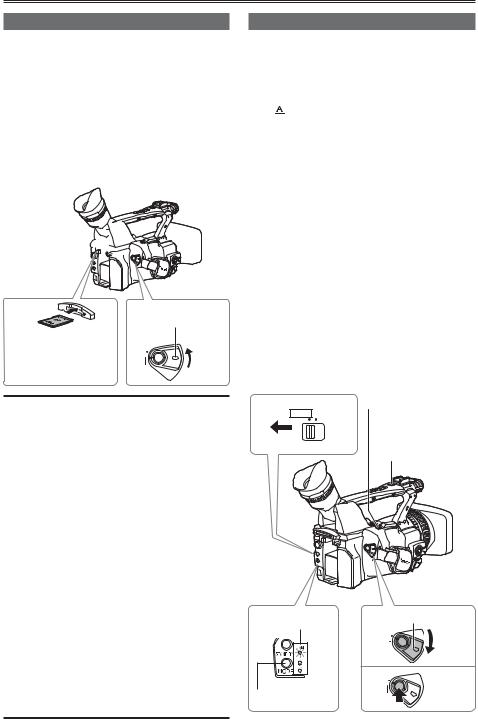
Preparing for recording
1 Set the camera’s power switch to OFF. (Page 22)
• Check that the mode lamp is off.
2 Tilt the viewfinder upwards, and open the SD Memory Card slot cover by sliding it to the left.
3 Fully insert an SD Memory Card into the card slot.
4 Close the SD Memory Card slot cover.
• Ensure that the cover firmly clicks into place.
2 

3
Insert the connector part in the direction shown here, and push until the card clicks firmly into place.
1 Lock release button
POWER
ON
OFF
•Do not perform any of the following operations while the SD Memory Card access lamp is flashing. Performing these operations may damage the SD Memory Card or its contents, or cause the camera to fail to operate correctly.
·Opening the card door and removing the SD Memory Card
·Switching off the power
·Connecting or disconnecting the USB connection cable
·Shaking or striking the camera
•Always format SD Memory Cards that have been used in other devices when first using them with this camera. (Page 32)
•If the system frequency of the camera is changed, the SD Memory Card will no
longer be able to be used. Such cards may be used again by formatting them with the current SYSTEM FREQ settings.
•When an SD Memory Card is formatted, all data recorded on the card will be erased and will not be restorable.
Save all important data to your computer.
•If “CHECK CARD” is displayed on the viewfinder or the LCD monitor, please remove the SD Memory Card and insert it again.
Shooting in auto mode
1 Turn the POWER switch to ON. (Page 22)
• Check that the mode lamp (CAM) is lighted red.
2 Switch the AUTO/MANUAL switch to AUTO to select auto mode.
•
 appears on the viewfinder and LCD monitor.
•The focus, gain, iris and white balance are adjusted automatically in accordance with the settings established for the items on the setting menu AUTO SW screen.
3 Press the START/STOP button (Red) to start shooting.
•Press again to return to the camera to the recording pause mode.
•Use the handle START/STOP button to make it easier to shoot from low angles.
The handle START/STOP button can be enabled (ON) and disabled (OFF) with the handle REC selector switch.
•Shooting is not possible when a menu screen is displayed. First, close the menu screen, and then press the START/STOP button.
•Shooting stops when the SD Memory Card slot cover is opened during shooting.
REC CHECK button
2 AUTO MANUAL
Handle
START/STOP button
Mode lamp |
1 LockPOWER release button |
|
|
|
ON |
|
|
OFF |
PB |
|
|
|
3 |
POWER |
|
ON |
|
Mode button |
OFF |
30
Loading...