


 Loading...
Advanced Hybrid System
Installation Manual
MODEL NO. KX-TA624
Please read this manual before connecting the Advanced Hybrid System.
System Highlights
System Capacity
Basic System |
Extensions |
8 |
|
Exchange lines |
3 |
Expansion |
Maximum extensions |
24 |
|
Maximum exchange lines |
6 |
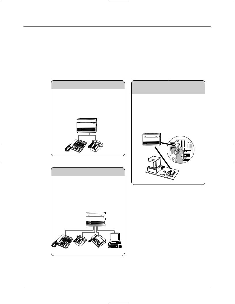
Special System Points
This system can expand the exchange lines and extension capacity by installing an optional card.
2– 24
External callers can call extensions in the system. If you install an optional card, an outgoing message will greet the caller and give information about how to access an extension.
3– 22
Hybrid
This system can accept Panasonic analogue proprietary telephones. Also, single line devices such as single line telephones, facsimiles and data terminals can be connected.
2

Precautions
FOR YOUR SAFETY PLEASE READ THE FOLLOWING TEXT CAREFULLY.
This appliance is supplied with a moulded three pin mains plug for your safety and convenience. A 5 amp fuse is fitted in this plug.
Should the fuse need to be replaced please ensure that the replacement fuse has a rating of 5 amps and that it is approved by ASTA or BSI to BS1362.
Check for the ASTA mark  or the BSI mark
  on the body of the fuse.
If the plug contains a removable fuse cover you must ensure that it is refitted when the fuse is replaced.
If you lose the fuse cover the plug must not be used until a replacement cover is obtained. A replacement fuse cover can be purchased from your local Panasonic Dealer.
IF THE FITTED MOULDED PLUG IS UNSUITABLE FOR THE SOCKET OUTLET IN YOUR HOME THEN THE FUSE SHOULD BE REMOVED AND THE PLUG CUT OFF AND DISPOSED OF SAFELY.
THERE IS A DANGER OF SEVERE ELECTRICAL SHOCK IF THE CUT OFF PLUG IS INSERTED INTO ANY 13 AMP SOCKET.
If a new plug is to be fitted please observe the wiring code as shown below. If in any doubt please consult a qualified electrician.
WARNING : THIS APPLIANCE MUST BE EARTHED.
IMPORTANT : The wires in this mains leads are coloured in accordance with the following code:
Green-and-yellow: Earth Blue: Neutral Brown: Live
As the colours of the wires in the mains lead of this apparatus may not correspond with the coloured markings identifying the terminals in your plug, proceed as follows.
The wire which is coloured GREEN-AND-YELLOW must be connected to the terminal in the plug which is marked with the letter E or by the safety earth symbol  or coloured GREEN or GREEN-AND-YELLOW.
The wire which is coloured BLUE must be connected to the terminal which is marked with the letter N or coloured BLACK.
The wire which is coloured BROWN must be connected to the terminal which is marked with the letter L or coloured RED.
How to replace the fuse : Open the-fuse compartment with a screwdriver and replace the fuse and fuse cover.
3

Precautions
This equipment should be used on PSTN lines requiring 2-wire Loop calling unguarded clearing with Loop Disconnect or DTMF address signalling.
The equipment must be connected to direct extension lines and a payphone should not be connected as an extension.
Operation in Power Failure
In the event of a power failure, two single line telephones connected to extension ports 01 and 09 will be directly connected to the following Exchange lines:
Exchange line 1 : extension port 01 Exchange line 4 : extension port 09
•Set the Dialling Mode (Tone or Pulse) of your telephone, according to the Exchange line.
•999 and 112 can be dialled on the apparatus for the purpose of making outgoing calls to the BT emergency (999) and (112) service.
Satisfactory performance can not be guaranteed for every allowed combination of host and subsidiary apparatus.
999 and 112 can be dialled on the apparatus after accessing the Exchange line for the purpose of making outgoing calls to the BT emergency (999) and (112) service.
During dialling, this apparatus may tinkle the bells of other telephones using the same line. this is not a fault and we advise you not to call Fault Repair Service.
‘Prevention of access by user. This apparatus is intended to be accessible only to authorised personnel. This apparatus must be installed in a locked room or similar environment, such that user access is prevented. Failure to prevent such user access will invalidate any approval given to this apparatus.’
Caution:
Do not push the PAUSE button more than twice following the initial access digit (or digits). Failure to comply with this requirement may result in unsatisfactory operation.
Notice:
This PBX should only be used on B•T lines on which specific BT services or facilities are provided.
CAUTION
Danger of explosion if battery is incorrectly replaced.
Replace only with the same or equivalent type recommended by the manufacturer.
Dispose of used batteries according to the manufacturer’s instructions.
4

Precautions
•The apparatus is designed to be installed and operated under controlled conditions of ambient temperature and a relative humidity not greater than 60 %.
•Avoid installing the apparatus in damp or humid environments, such as bathrooms or swimming pools.
•The apparatus shall not be exposed to dripping or splashing.
•Keep the unit away from heating appliances and electrical noise generating devices such as fluorescent lamps, motors and televisions. These noise sources can interfere with the performance of the Advanced Hybrid System.
•This unit should be kept free of dust, moisture, high temperature (more than 40 ˚C) and vibration, and should not be exposed to direct sunlight.
•Never attempt to insert wires, pins, etc. into the vents or other holes of this unit.
•If there is any trouble, disconnect the unit from the telephone line. Plug a single line telephone into the telephone line. If the telephone operates properly, do not reconnect your system to the line until the system has been repaired. If the telephone does not operate properly, chances are that the problem is in the telephone network, and not in your system.
•Do not use benzine, thinner, or the like, or any abrasive powder to clean the cabinet. Wipe it with a soft cloth.
WARNING
THIS UNIT MAY ONLY BE INSTALLED AND SERVED BY QUALIFIED SERVICE PERSONNEL.
WHEN A FAILURE OCCURS WHICH RESULTS IN THE INTERNAL PARTS BECOMING ACCESSIBLE, DISCONNECT THE POWER SUPPLY CORD IMMEDIATELY AND RETURN THIS UNIT TO YOUR DEALER.
DISCONNECT THE TELECOM CONNECTION BEFORE DISCONNECTING THE POWER CONNECTION PRIOR TO RELOCATING THE EQUIPMENT, AND RECONNECT THE POWER FIRST.
THIS UNIT IS EQUIPPED WITH AN EARTHING CONTACT PLUG. FOR SAFETY REASONS THIS PLUG MUST ONLY BE CONNECTED TO AN EARTHING CONTACT SOCKET WHICH HAS BEEN INSTALLED ACCORDING TO REGULATIONS.
THE POWER SUPPLY CORD IS USED AS THE MAIN DISCONNECT DEVICE, ENSURE THAT THE SOCKET-OUTLET IS LOCATED/INSTALLED NEAR THE EQUIPMENT AND IS EASILY ACCESSIBLE.
TO PREVENT THE RISK OF FIRE OR ELECTRIC SHOCK, DO NOT EXPOSE THIS PRODUCT TO RAIN OR MOISTURE.
5
Precautions
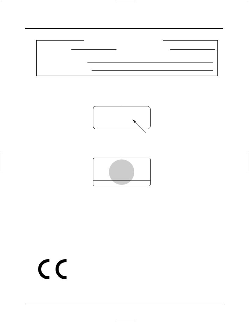
For your future reference
SERIAL NO. |
DATE OF PURCHASE |
(found on the bottom of the unit)
NAME OF DEALER
DEALER’S ADDRESS
Note • This Installation Manual does not show the complete model number that indicates the country where your equipment should be used. The model number of your unit is found on the label affixed to the unit.
MODEL NO. – – – – – – – –
(label)
APPROVED for connection to telecommunication systems specified in the instructions for use subject to the conditions set out in them.
610186
Warning:
This is a Class A Product. In a domestic environment this product may cause radio interference in which case the user may be required to take adequate measures.
This unit complies with the EU Directives.
73 |
/ 23 / EEC |
“Electrical equipment for use within certain voltage limits.” |
|
|
89 |
/ 336 / EEC |
“Electromagnetic compatibility” (basic standard) |
|
92 |
/ 31 / EEC |
“Electromagnetic compatibility” (amendment) |
|
|||
93 |
/ 68 / EEC |
“Marking” |
|
The CE mark on this unit certifies compliance with the above mentioned Directives.
6

Introduction
Structure of the Manual
This manual consists of the following sections:
Section 1. Basic System Construction
Provides general information on the system including connection diagrams.
Section 2. Installation
Contains the system installation and wiring instructions, as well as how to install the optional cards.
Section 3. Features
Describes the optional and programmable features in alphabetical order. It also provides information about the conditions, required System Programming, connection references, related features and operating instructions references for every feature.
Section 4. System Programming
Describes the steps required to assign features to extensions or to the system.
Section 5. Appendix
Provides specifications and the default values of the System Programming.
Section 6. Troubleshooting
Provides information for system and telephone troubleshooting.
Section 7. Programming Tables
Provides programming tables for user-programmed data.
Description of the Symbols Mainly Used in this manual
!
Additional information and conditions.
The feature or program references.
7

Contents
Section 1 |
Basic System Construction |
|
Section 2 |
Installation |
|
2.1 |
Before Installation ................................................................................. |
2-2 |
2.2 |
Unpacking .............................................................................................. |
2-4 |
2.3 |
Names and Locations ............................................................................ |
2-4 |
2.4 |
Wall Mounting ....................................................................................... |
2-5 |
2.5 |
Frame Ground Connection .................................................................. |
2-6 |
2.6 |
Opening the Top Front Cover .............................................................. |
2-6 |
2.7 |
Exchange Line Connection................................................................... |
2-7 |
2.8 |
Extension Connection ........................................................................... |
2-10 |
2.9 |
External Pager (Paging Equipment) Connection............................... |
2-12 |
2.10 |
External Music Connection .................................................................. |
2-13 |
2.11 |
Parallelled Telephone Connection ....................................................... |
2-14 |
2.12 |
Polarity Sensitive Telephone Connection ............................................ |
2-15 |
2.13 |
Printer and PC Connection.................................................................. |
2-16 |
2.14 |
Location of Optional Cards.................................................................. |
2-19 |
2.15 |
OGM/FAX Detection Card Installation .............................................. |
2-19 |
2.16 |
Doorphone and Door Opener Connection .......................................... |
2-21 |
2.17 |
Installing a 3-CO Line & 8 Ext Expansion Card (KX-TA62477) |
|
|
and 8 SLT Extn. Expansion Card (KX-TA62474) ......................... |
2-25 |
2.18 |
Auxiliary Connection for Power Failure Transfer ............................. |
2-30 |
2.19 |
Securing the Cords................................................................................ |
2-31 |
2.20 |
Closing the Front Cover ....................................................................... |
2-31 |
2.21 |
Starting the System for the First Time ............................................... |
2-32 |
2.22 |
System Restart ....................................................................................... |
2-33 |
2.23 |
System Data Clear................................................................................. |
2-34 |
Section 3 |
Features |
|
A |
Absent Message Capability ................................................................ |
3-2 |
|
Account Code Entry ........................................................................... |
3-3 |
|
Alternate Calling – Ring/Voice .......................................................... |
3-3 |
|
Automatic Callback Busy (Camp-On) ............................................... |
3-4 |
|
Automatic Exchange Line Access Number........................................ |
3-4 |
|
Automatic Route Selection (ARS) ..................................................... |
3-5 |
B |
Busy Extension Signalling ................................................................. |
3-10 |
C |
Call Barring ........................................................................................ |
3-11 |
|
Call Barring — Extension Lock Boundary Class .............................. |
3-13 |
|
Call Barring for System Speed Dialling ........................................... |
3-13 |
|
Call Barring Override by Account Codes .......................................... |
3-14 |
|
Call Forwarding.................................................................................. |
3-15 |
|
Calling Party Control (CPC) Signal Detection .................................. |
3-15 |
|
Call Park ............................................................................................. |
3-16 |
|
Call Pickup ......................................................................................... |
3-17 |
|
Call Splitting....................................................................................... |
3-17 |
8

Contents
|
Call Transfer – to Exchange Line ...................................................... |
3-18 |
|
Call Transfer – to Extension............................................................... |
3-18 |
|
Call Waiting ........................................................................................ |
3-19 |
|
Conference (3-party) .......................................................................... |
3-20 |
|
Conference (5-party) .......................................................................... |
3-21 |
D |
Data Line Security.............................................................................. |
3-21 |
|
Date and Time Setting ........................................................................ |
3-22 |
|
Direct In Line (DIL) ........................................................................... |
3-22 |
|
Direct Inward System Access (DISA)............................................... |
3-22 |
|
Display Contrast Adjustment (KX-T7130 only) ................................ |
3-28 |
|
Distinctive Dial Tones ........................................................................ |
3-28 |
|
Do Not Disturb (DND)....................................................................... |
3-29 |
|
Door Opener ....................................................................................... |
3-30 |
|
Doorphone Call .................................................................................. |
3-30 |
|
DSS Console....................................................................................... |
3-31 |
E |
Emergency Call .................................................................................. |
3-32 |
|
Exchange Line Ringing Selection ...................................................... |
3-32 |
|
Executive Busy Override.................................................................... |
3-33 |
|
Extension Button Confirmation (KX-T7130 only) ............................ |
3-33 |
|
Extension Feature Clear ..................................................................... |
3-34 |
|
Extension Group................................................................................. |
3-35 |
|
Extension Hunting .............................................................................. |
3-36 |
|
Extension Lock................................................................................... |
3-36 |
|
Extension Password / System Password ............................................ |
3-37 |
|
External Feature Access ..................................................................... |
3-38 |
F |
Flexible Buttons.................................................................................. |
3-39 |
H |
Handsfree Answerback ....................................................................... |
3-40 |
|
Handsfree Operation........................................................................... |
3-40 |
|
Hold .................................................................................................... |
3-40 |
|
Host PBX Access................................................................................ |
3-41 |
I |
Intercept Routing ............................................................................... |
3-42 |
|
Intercom Calling ................................................................................. |
3-42 |
L |
Language Selection ............................................................................ |
3-43 |
|
Limited Call Duration ........................................................................ |
3-43 |
|
Line Access Keys ............................................................................... |
3-43 |
|
Log-In/Log-Out .................................................................................. |
3-44 |
M |
Message Waiting................................................................................. |
3-45 |
|
Microphone Mute ............................................................................... |
3-45 |
|
Music on Hold / Background Music (BGM) ..................................... |
3-46 |
O |
One-Touch Dialling ............................................................................ |
3-46 |
|
Operator / Manager Extension ........................................................... |
3-47 |
|
Operator Call ...................................................................................... |
3-47 |
|
Outgoing Message (OGM) ................................................................. |
3-48 |
|
Outside Calling................................................................................... |
3-52 |
9

Contents
P |
Paging ................................................................................................. |
3-53 |
|
Parallelled Telephone Connection ...................................................... |
3-54 |
|
Personal Speed Dialling ..................................................................... |
3-54 |
|
Pickup Dialling................................................................................... |
3-55 |
|
Polarity Reverse Detection ................................................................. |
3-55 |
|
Power Failure Transfer ....................................................................... |
3-56 |
|
Preferred Line Assignment — Incoming ........................................... |
3-56 |
|
Preferred Line Assignment — Outgoing............................................ |
3-57 |
|
Proprietary Telephone Setting Data Default Set ................................ |
3-57 |
|
Pulse to Tone Conversion ................................................................... |
3-58 |
R |
Recall .................................................................................................. |
3-58 |
|
Recall Button on a Single Line Telephone......................................... |
3-59 |
|
Receiving Calls................................................................................... |
3-59 |
|
Redial.................................................................................................. |
3-60 |
|
Ringing Pattern Selection ................................................................... |
3-60 |
|
Room Monitor .................................................................................... |
3-61 |
S |
Secret Dialling .................................................................................... |
3-62 |
|
Self-Extension Number Confirmation (KX-T7130 only) .................. |
3-62 |
|
Station Message Detail Recording (SMDR) ...................................... |
3-63 |
|
System Data Default Set .................................................................... |
3-64 |
|
System Speed Dialling ....................................................................... |
3-65 |
T |
Timed Reminder ................................................................................. |
3-65 |
|
Time (Day/Night/Lunch) Service....................................................... |
3-66 |
U |
Uniform Call Distribution (UCD) ...................................................... |
3-67 |
V |
Voice Mail Integration for KX-TVP100 ............................................ |
3-71 |
|
Volume Control ................................................................................. |
3-74 |
W |
Walking COS ...................................................................................... |
3-74 |
Section 4 |
System Programming |
|
4.1 |
Before System Programming ............................................................... |
4-2 |
4.2 |
System Programming............................................................................ |
4-5 |
|
[000] Date and Time Setting.............................................................. |
4-5 |
|
[001] System Speed Dialling Entry ................................................... |
4-5 |
|
[002] System Password...................................................................... |
4-6 |
|
[003] DSS Console Port Assignment ................................................ |
4-7 |
|
[004] Paired Telephone Assignment for DSS Console...................... |
4-7 |
|
[005] One-Touch Transfer Using a DSS Button ............................... |
4-8 |
|
[006] Time (Day/Night/Lunch) Service Changing Mode ................. |
4-8 |
|
[007] Time (Day/Night/Lunch) Service Start Time .......................... |
4-9 |
|
[008] Operator Assignment .............................................................. |
4-9 |
|
[009] Extension Number Assignment .............................................. |
4-10 |
|
[010] LCD Time Display Selection ................................................... |
4-11 |
|
[011] System Speed Dialling Name Setting...................................... |
4-12 |
|
[012] Alternative Feature Numbering Plan ....................................... |
4-13 |
|
[100] Hunting Group Set ................................................................... |
4-14 |
10
Contents
[101] Hunting Type............................................................................ |
|
4-14 |
[102] Voice Mail Port for KX-TVP100............................................. |
4-15 |
|
[103] DTMF Integration for KX-TVP100......................................... |
4-16 |
|
[104] Hold Mode Selection ............................................................... |
|
4-17 |
[105] Conference Tone ...................................................................... |
|
4-17 |
[106] External Paging Access Tone ................................................... |
4-18 |
|
[107] DTMF Receiver Check ............................................................ |
|
4-18 |
[108] Recall Mode for a Locked Extension ...................................... |
4-18 |
|
[109] CO Indicator Assignment......................................................... |
|
4-19 |
[110] Recall Key Mode...................................................................... |
|
4-19 |
[111] Hold Music Selection............................................................... |
|
4-20 |
[112] DSS Console Indication Mode ................................................ |
4-20 |
|
[115] Extension Ringing Pattern Selection ....................................... |
4-21 |
|
[116] Conference Pattern Selection ................................................... |
4-21 |
|
[117] Call Pickup Tone ...................................................................... |
|
4-22 |
[118] Pulse Restriction ...................................................................... |
|
4-22 |
[119] Redialling after Pulse to Tone Conversion .............................. |
4-22 |
|
[120] Bell Frequency ......................................................................... |
|
4-23 |
[121] Automatic Exchange Line Access Number Selection ............. |
4-23 |
|
[122] Automatic Rotation for Exchange Line Access....................... |
4-23 |
|
[123] Break Ratio .............................................................................. |
|
4-24 |
[124] SLT Ringing Mode Selection................................................... |
4-24 |
|
[125] Call Barring Check for |
and #.............................................. |
4-24 |
[126] DSS Off-Hook Mode ............................................................... |
|
4-25 |
[127] Pickup Group Set ..................................................................... |
|
4-25 |
[200] Hold Recall Time ..................................................................... |
|
4-26 |
[201] Transfer Recall Time................................................................ |
|
4-26 |
[202] Call Forwarding Start Time ..................................................... |
4-27 |
|
[203] Pickup Dial Delay Time........................................................... |
|
4-27 |
[204] Call Duration Count Start Time .............................................. |
4-28 |
|
[206] Dialling Start Time................................................................... |
|
4-28 |
[207] Recall Timing Range Selection................................................ |
4-29 |
|
[208] Interdigit Time.......................................................................... |
|
4-29 |
[210] DTMF Time ............................................................................. |
|
4-30 |
[211] No Dial Disconnection............................................................. |
|
4-30 |
[212] Exchange Line Duration Time Limit ....................................... |
4-31 |
|
[213] Bell Off Detection .................................................................... |
|
4-31 |
[300] Carrier Excepted Code Assignment ......................................... |
4-32 |
|
[301] Call Barring – System Speed Dialling Boundary Class .......... |
4-32 |
|
[302]-[305] Call Barring – Classes 2 through 5 Denied Codes........ |
4-33 |
|
[306] Call Barring – Exception Codes .............................................. |
4-34 |
|
[309] Emergency Dial Number Set ................................................... |
4-34 |
|
[310] Account Codes ......................................................................... |
|
4-35 |
[311] Automatic Pause Insertion Codes ............................................ |
4-35 |
|
[312] Call Barring – Extension Lock Boundary Class ..................... |
4-36 |
|
11

Contents
[350] ARS Selection .......................................................................... |
4-37 |
|
[351]-[354] |
Routes 1 through 4 Selection Codes (Leading Digits).. |
4-37 |
[355]-[358] |
Routes 1 through 4 Exception Codes ........................... |
4-38 |
[359] 1st Carrier Selection Code (BT Line Access Code) ................ |
4-38 |
|
[360] ARS Modification – Removed Digits ...................................... |
4-39 |
|
[361] ARS Modification – Added Number ....................................... |
4-39 |
|
[362] ARS Dial Tone Pattern Selection............................................. |
4-40 |
|
[363] ARS Interdigit Time................................................................. |
4-40 |
|
[364] ARS Trunk Group .................................................................... |
4-41 |
|
[381]-[384] |
Routes 1 through 4 Authorisation Codes....................... |
4-42 |
[385]-[388] |
Routes 1 through 4 Itemised Bill................................... |
4-43 |
[389] Itemised Bill Code Assignment ............................................... |
4-43 |
|
[400] Exchange Line Connection Assignment .................................. |
4-44 |
|
[401] Dial Mode ................................................................................ |
4-44 |
|
[402] Pulse Speed Selection .............................................................. |
4-45 |
|
[403] Host PBX Access Codes .......................................................... |
4-45 |
|
[404] Trunk Group Assignment......................................................... |
4-46 |
|
[405]-[407] |
Flexible Outward Dialling Assignment |
|
|
—Day/Night/Lunch ....................................................... |
4-47 |
[408]-[410] Flexible Ringing Assignment —Day/Night/Lunch ....... |
4-48 |
|
[411]-[413] Delayed Ringing Assignment —Day/Night/Lunch ....... |
4-49 |
|
[414]-[416] Exchange Line Mode —Day/Night/Lunch.................... |
4-50 |
|
[417] Pause Time ............................................................................... |
4-51 |
|
[418] Recall Time .............................................................................. |
4-52 |
|
[419] Automatic Designated Exchange Line Access ........................ |
4-52 |
|
[420] Calling Party Control (CPC) Signal......................................... |
4-53 |
|
[421] CPC Detection for Outgoing Calls .......................................... |
4-54 |
|
[422] Disconnect Time ...................................................................... |
4-54 |
|
[423] Exchange Line Ringing Pattern Selection ............................... |
4-55 |
|
[424] Reverse (Polarity) Circuit Assignment .................................... |
4-56 |
|
[500] DISA Incoming Dialling Mode Selection ............................... |
4-57 |
|
[501] DISA |
Built-in Auto Attendant ................................................ |
4-58 |
[502] OGM Mode Selection .............................................................. |
4-59 |
|
[503] FAX Connection....................................................................... |
4-60 |
|
[504] DISA Delayed Answer Time ................................................... |
4-60 |
|
[505] DISA Waiting Time after OGM............................................... |
4-60 |
|
[506] DISA Busy Mode..................................................................... |
4-61 |
|
[507] DISA Intercept Mode............................................................... |
4-61 |
|
[508] DISA Ringing Time before Intercept ...................................... |
4-62 |
|
[509] DISA Ringing Time after Intercept ......................................... |
4-62 |
|
[510] DISA No Dial Mode ............................................................... |
4-63 |
|
[513] Cyclic Tone Detection.............................................................. |
4-63 |
|
[514] FAX Tone Detection ................................................................ |
4-64 |
|
[515] Intercept Time for Internal DISA ............................................ |
4-64 |
|
12

Contents
[516] DISA Incoming Assignment .................................................... |
4-65 |
[517] DISA AA Wait Time ................................................................ |
4-65 |
[519] DISA OGM Mute Time ........................................................... |
4-66 |
[520] UCD Group .............................................................................. |
4-66 |
[521] UCD Busy Waiting Time ......................................................... |
4-66 |
[522] UCD OGM Message Interval Time ......................................... |
4-67 |
[523] UCD Busy Mode...................................................................... |
4-67 |
[524] UCD Intercept Mode................................................................ |
4-68 |
[525] UCD Ringing Time before Intercept ....................................... |
4-68 |
[526] UCD Ringing Time after Intercept .......................................... |
4-68 |
[600] Extension Group Assignment .................................................. |
4-69 |
[601]-[603] Call Barring – Class of Service Assignment |
|
—Day/Night/Lunch ....................................................... |
4-69 |
[604] Extension Name Setting........................................................... |
4-70 |
[605] Account Code Entry Mode ...................................................... |
4-71 |
[606] Call Transfer to an Exchange Line .......................................... |
4-72 |
[607] Call Forwarding to an Exchange Line ..................................... |
4-72 |
[608] Executive Busy Override ......................................................... |
4-73 |
[609] Do Not Disturb Override ......................................................... |
4-73 |
[610] Parallelled Telephone Connection............................................ |
4-74 |
[611] TAM (Telephone Answering Machine) Extension .................. |
4-74 |
[612] Room Monitor Assignment...................................................... |
4-75 |
[613] Exchange Line Duration Time Limit Selection ....................... |
4-75 |
[614] Internal Pulse Detection ........................................................... |
4-76 |
[615] LCD Language Assignment ..................................................... |
4-77 |
[700]-[702] Doorphone Ringing Assignment —Day/Night/Lunch .. |
4-78 |
[703]-[705] Door Opener Assignment —Day/Night/Lunch ............. |
4-79 |
[706] Doorphone Ringing / Tone Pattern Selection .......................... |
4-80 |
[707] Doorphone Access Tone Selection........................................... |
4-80 |
[708] Doorphone Ringing Time ........................................................ |
4-81 |
[709] Door Opener Time ................................................................... |
4-81 |
[800] SMDR RS-232C Communication Parameters......................... |
4-82 |
[801] SMDR Parameter ..................................................................... |
4-83 |
[802] Incoming/Outgoing Call Selection for Printing....................... |
4-83 |
[803] Secret Speed Dialling / One-Touch Dialling Printing ............. |
4-84 |
[804] System Data Dump .................................................................. |
4-84 |
[805] SMDR Account Code Selection .............................................. |
4-85 |
[806] SMDR Language Assignment.................................................. |
4-86 |
[998] ROM Version............................................................................ |
4-86 |
[999] System Data Clear.................................................................... |
4-87 |
13

Contents
Section 5 |
Appendix |
|
5.1 |
Default Values ........................................................................................ |
5-2 |
5.2 |
Specifications ......................................................................................... |
5-7 |
Section 6 |
Troubleshooting |
|
6.1 |
While Installing ..................................................................................... |
6-2 |
6.2 |
While Connecting .................................................................................. |
6-3 |
6.3 |
While Operating .................................................................................... |
6-4 |
Section 7 |
Programming Tables |
|
Template |
|
|
14

Section 1
Basic System Construction

1 Basic System Construction
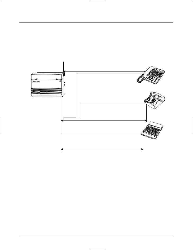
The KX-TA624 has a basic capacity of 8 extensions and 3 exchange lines. It is capable of supporting Panasonic analogue proprietary telephones, and single line devices such as single line telephones, facsimiles and data terminals.
To expand its capabilities, the system can be equipped with optional components or customer-supplied peripherals such as an external speaker, external music source (e.g. a radio) and door opener.
System Connection Diagram
|
|
|
6 Exchange Lines |
|
|||
|
|
|
|
|
|
to exchange lines 1 – 3 (initial) |
|
|
|
|
|
|
|
to exchange lines 4 – 6 (additional) |
|
|
|
|
|
|
|
(Lightning Protectors) |
|
|
|
|
External Music Source |
|
|||
|
|
|
|
|
|
Amplifier |
Speaker |
Printer |
or |
Computer |
|
|
|
Extension ports 01 – 08 (initial) |
|
|
|
|
24 Extensions |
||||
|
|
|
Extension ports 09 – 24 (additional) |
||||
|
|
(one pair) |
|
|
|
(two pair) |
|
|
|
|
|
|
|
|
|
|
|
|
|
|
(two pair) |
|
|
|
Single Line Telephone |
|
|
|
|
|
|
|
|
(one pair) |
|
|
|
|
KX-T7020 |
|
|
|
|
|
|
|
|
|
|
|
KX-T7130 |
|
(two pair) |
||
|
|
Data Terminal |
|
|
|
|
|
Door Openers |
|
|
|
|
|
|
KX-T7040 |
|
(one pair) |
|
|
|
(two pair) |
||
|
|
|
|
|
|||
Panasonic |
|
Cordless Phone |
|
|
|
|
|
|
|
|
|
|
|
|
|
|
|
(one pair) |
|
|
|
|
KX-T7050 |
|
|
|
|
|
|
|
|
Panasonic |
|
|
|
|
|
|
|
|
Telephone Answering Machine |
! |
• We recommend connecting a display |
||||
Panasonic |
with Facsimile |
|
proprietary telephone at extension port 01. |
||||
|
|
|
|
|
|
||
|
|
(one pair) |
|
• Parallel connection of telephones is |
|||
|
|
|
|
possible. ( 2.11, Parallelled Telephone |
|||
|
|
|
|
|
|||
|
|
|
|
|
Connection) |
|
|
|
|
|
|
• A proprietary telephone cannot be |
|||
Panasonic |
|
|
|
|
connected to extension ports 17 through 24. |
||
|
|
|
|
|
|||
Doorphones |
|
|
|
|
Only a single line telephone (SLT) can be |
||
KX-T30865 |
Voice Processing System |
|
|
connected. |
|
||
1-2 |
Basic System Construction |
: needs optional card. |

Section 2
Installation

2.1Before Installation
Please read the following notes concerning installation and connection before installing the system and terminal equipment.
Safety Installation Instructions
When installing telephone wiring, basic safety precautions should always be followed to reduce the risk of fire, electric shock and injury to persons, including the following:
1.Never install telephone wiring during a lightning storm.
2.Never install telephone ports in wet locations unless the port is specifically designed for wet locations.
3.Never touch uninsulated telephone wires or terminals unless the telephone line has been disconnected at the network interface.
4.Use caution when installing or modifying telephone lines.
Installation Precautions
This system is designed for wall mounting only. Avoid installing in the following places. (Doing so may result in malfunction, noise, or discolouration.)
1.In direct sunlight and hot, cold, or humid places. (Temperature range: 0 °C – 40 °C)
2.Sulphuric gases produced in areas where there are thermal springs, etc. may damage the equipment or contacts.
3.Places in which shocks or vibrations are frequent or strong.
4.Dusty places, or places where water or oil may come into contact with the system.
5.Near high-frequency generating devices such as sewing machines or electric welders.
6.On or near computers, telexes, or other office equipment, as well as microwave ovens or air conditioners. (It is preferable not to install the system in the same room with the above equipment.)
7.Install at least 1.8 m away from radios and televisions. (Both the system and Panasonic proprietary telephones)
8.Do not obstruct area around the system (for reasons of maintenance and inspection — be especially careful to allow space for cooling above and at the sides of the system).
Wiring Precautions
Be sure to follow these instructions when wiring the unit:
1.Do not wire the telephone cable in parallel with an AC power source, computer, telex, etc. If the cables are run near those wires, shield the cables with metal tubing or use shielded cables and ground the shields.
2.If cables are run on the floor, use protectors to prevent the wires from being stepped on. Avoid wiring under carpets.
3.Avoid using the same power supply outlet for computers, telexes, and other office equipment. Otherwise, the system operation may be interrupted by the induction noise from such equipment.
2-2 Installation
2.1Before Installation
4.Please use one pair telephone wire for extension connection of (telephone) equipment such as single line telephones, data terminals, answering machines, computers, voice processing systems, etc., except Panasonic proprietary telephones (e.g. KX-T7130).
5.Unplug the system during wiring. After all of the wiring is completed, plug in the system.
6.Mis-wiring may cause the system to operate improperly. Refer to Section 6.1 “While Installing” and Section 6.2 “While Connecting”.
7.If an extension does not operate properly, disconnect the telephone from the extension line and then connect again, or turn off the Power Switch of the system and then on again.
8.The system is equipped with a 3-wire grounding type plug. This is a safety feature. If you are unable to insert the plug into the outlet, contact your electrician to replace your obsolete outlet. Do not defeat the purpose of the grounding-type plug.
9.Exchange lines should be installed with lightning protectors. For details, refer to Section 2.7 “Exchange Line Connection”, Installing Lightning Protectors.
POWER
|
Warning: |
|
Static sensitive devices |
|
are used. To protect |
|
printed circuit boards |
|
from static electricity, do |
|
not touch connectors |
|
indicated to the left. To |
|
discharge body static, |
Side View |
touch ground or wear a |
|
grounding strap. |
Warning: Static sensitive connectors
Installation 2-3

2.2Unpacking
Unpack the box and check the items below.
|
Main Unit |
|
1 |
|
|
Music Source Connector |
|
1 |
|
|
||||||||
|
AC Cord |
|
|
|
|
|
|
Order No. PQJP1E1Z |
|
|
|
|||||||
|
|
|
|
|
|
|
|
|
|
|
||||||||
|
Order No. PSWAT206E |
|
1 |
|
|
Installation Manual |
|
1 |
|
|
||||||||
|
|
|
|
|
|
|
|
|
|
|||||||||
|
Telephone Line Cords |
|
|
|
|
|
|
Order No. PSQX1708Y |
|
|
|
|||||||
|
|
|
|
|
|
|
|
|
|
|
||||||||
|
(2-conductor wiring) |
|
3 |
|
|
Operating Instructions |
|
1 |
|
|
||||||||
|
Order No. PSJA1066Z |
|
|
|
|
|
|
Order No. PSQX1709Y |
|
|
|
|||||||
|
|
|
|
|
|
|
|
|
|
|
||||||||
|
Telephone Line Cords |
|
|
|
|
|
|
Operating Instructions for |
|
|
|
|
||||||
|
(4-conductor wiring) |
|
8 |
|
|
the Caller ID Card |
|
1 |
|
|
||||||||
|
Order No. PQJA151Z |
|
|
|
|
|
|
Order No. PSQX1744Y |
|
|
|
|
||||||
|
Screws (Wall Mounting) |
|
3 |
|
|
SLT User Guide |
|
2 |
|
|
||||||||
|
Order No. PQHE5004Z |
|
|
|
Order No. PSQX1753Z |
|
|
|
||||||||||
|
|
|
|
|
|
|
|
|
|
|
||||||||
|
Washers (Wall Mounting) |
3 |
|
|
System Clear Leaflet |
|
1 |
|
|
|||||||||
|
Order No. XWG35FY |
|
|
|
Order No. PSQW1412Y |
|
|
|
||||||||||
|
|
|
|
|
|
|
|
|
|
|
||||||||
|
Pager Connector |
|
1 |
|
|
Feature Number Leaflet |
|
1 |
|
|
||||||||
|
Order No. PQJP1E1Z |
|
|
|
Order No. PSQW1472Y |
|
|
|
||||||||||
|
|
|
|
|
|
|
|
|
|
|
||||||||
|
|
|
|
|
|
|
|
|
|
|
|
|||||||
|
|
|
|
Optional Cards (For your reference) |
|
|
|
|
|
|||||||||
|
|
|
|
|
|
|
|
|
||||||||||
|
|
|
|
|
|
|
|
|
|
|
|
|
|
|
|
|
|
|
|
KX-TA62460 |
|
|
|
|
KX-TA62474 |
|
|
|
KX-TA62477 |
|
|
|
|||||
|
|
|
|
|
|
|
|
|
|
|
|
|
|
|
||||
|
Screws |
|
|
1 |
|
|
Screws |
2 |
|
Extension Bolts |
|
2 |
|
|||||
|
Order No. XYN3+F12FN |
|
|
|
|
Order No. XYN3+F8 |
|
Order No. PSHE1051Z |
|
|
||||||||
|
|
|
|
|
|
|
|
|
|
|||||||||
|
Terminal Boxes |
|
|
2 |
|
|
Extension Connectors |
2 |
|
Extension Connectors |
2 |
|
||||||
|
Order No. PQJS1T30Z |
|
|
|
|
Order No. PSJP36A67Z |
|
Order No. PSJP36A67Z |
|
|
||||||||
|
|
|
|
|
|
|
|
|
|
|||||||||
|
Telephone Line Cords |
|
|
|
|
|
|
|
|
|
|
|
Spacer |
|
1 |
|
||
|
(4-conductor wiring) |
|
|
2 |
|
|
|
|
|
|
|
|
Order No. PSHR1172Z |
|
|
|||
|
|
|
|
|
|
|
|
|
|
|
|
|
||||||
|
Order No. PQJA48W |
|
|
|
|
|
|
|
|
|
|
|
|
|
|
|
|
|
|
|
|
|
|
|
|
|
|
|
|
|
|
|
|
|
|
|
|
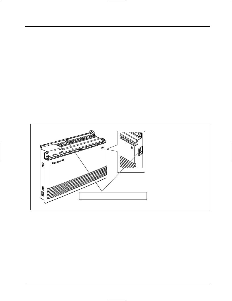
2.3Names and Locations
Extension Ports |
Strap (for cables) |
|
Paging Port |
||
Exchange Line Ports |
||
External Music Port |
||
|
||
|
POWER |
Power Switch 

Serial Interface
(RS-232C)
Protective Earth Terminal
Side View
AC Inlet |
Power Indicator |
2-4 Installation
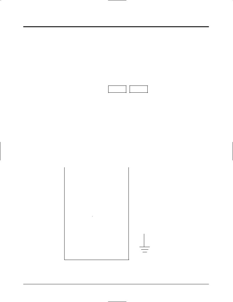
2.4Wall Mounting
This set is designed for wall mounting only. The wall where the main unit is to be mounted must be able to support the weight of the main unit. If screws other than the ones supplied are used, use screws with the same diameter as the ones enclosed.
Mounting on a Wooden Wall
1. Place the template (on the last page) on the wall to mark the screw positions.
Template
2. Install the screws (included) into the wall.
Wooden
Wall
Drive the screw to this position
3. Hook the main unit on the screw heads.
Installation 2-5
2.5Frame Ground Connection
IMPORTANT!!!
Connect the frame of the main unit to the ground.
1. Loosen the screw.
2. Insert the grounding wire (usersupplied).
3. Tighten the screw. |
Screw |
|
4.Connect the grounding wire to the ground.
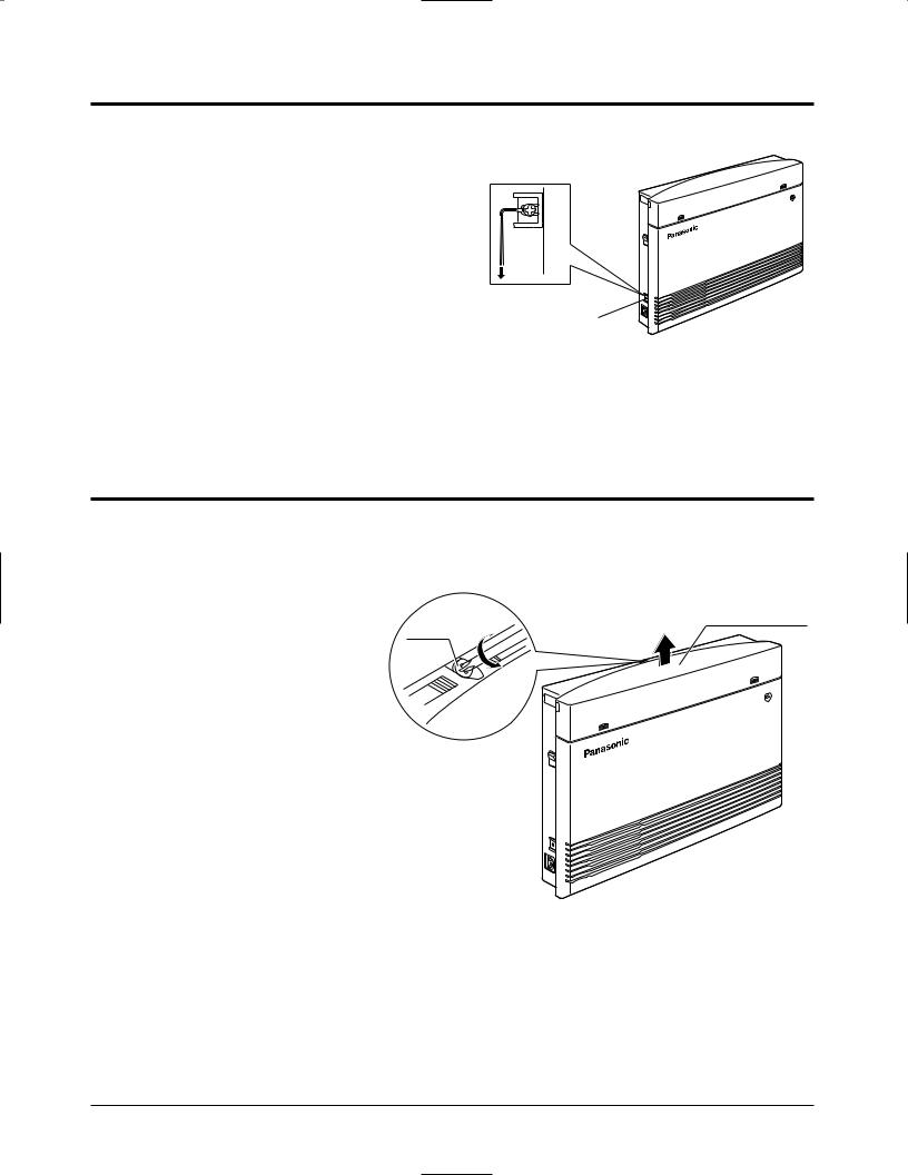
2.6Opening the Top Front Cover
1.Loosen the screw.
2.Remove the top front cover.
Top front cover
Screw
! • The screw cannot be removed from the cover.
2-6 Installation
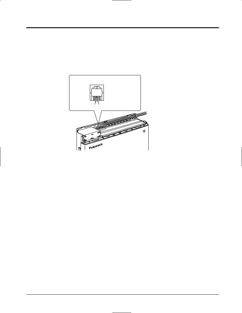
2.7Exchange Line Connection
Connection
1.Insert the modular plugs of the telephone line cords (2-conductor wiring) into the ports (CO 1 through 3) on the system.
2.Connect the line cords to the terminal board or the ports from the Local Exchange.
View of TEL Port (Exchange Line)
A: Tip
B: Ring
A B
 To Terminal Board or Ports from the Local Exchange
POWER
!• Exchange Line ports are at TNV.
Installing Lightning Protectors
A lightning protector is a device to be installed on an exchange line to prevent a dangerous surge from entering the building and damaging the equipment.
A dangerous surge can occur if a telephone line comes in contact with a power line. Problems due to lightning surges have been steadily increasing with the development of electronic equipment.
In many countries, there are regulations requiring the installation of a lightning protector. A lightning strike to a telephone cable which is 10 m above ground can be as high as 200 000 V. This system should be installed with lightning protectors. In addition, grounding (connection to earth ground) is very important to protect the system ( 2.5, Frame Ground Connection).
Installation 2-7
2.7Exchange Line Connection
Installation
CO |
Lightning |
CO |
|
|
|
CO |
|
|
|
|
|||||||||||
|
|
|
|
|
|
|
|
|
|
|
System |
|
|||||||||
|
|
|
|
|
|
|
|
|
|
|
|
||||||||||
|
Protectors |
|
|
Terminal |
|
|
|
|
|
||||||||||||
|
|
|
|
|
|
|
|
|
|
||||||||||||
|
|
|
|
EXTN. |
|
|
|
|
|||||||||||||
|
|
|
|
|
|
|
|
|
|
|
Board |
|
|
Protective |
|
||||||
|
|
|
|
|
|
|
|
|
|
|
|
|
|
|
|
|
|
|
Earth |
|
|
|
|
|
|
|
|
|
|
|
|
|
|
|
|
|
|
|
|
|
|||
|
|
|
|
|
|
|
|
|
|
|
|
|
|
|
|
|
|
|
Terminal |
|
|
|
|
|
|
|
|
|
|
|
|
|
|
|
|
|
|
|
|
|
|||
|
|
|
|
|
|
|
|
|
EXTN. |
|
|
|
EXTN. |
|
|
Frame Ground |
|||||
|
|
|
|
|
|
|
|
|
|
|
|
|
|
|
|
|
|
|
|
||
|
|
|
|
|
|
|
|
|
|
TEL |
|
|
TEL |
|
|
|
|||||
|
|
|
|
|
|
|
|
|
|
|
|
|
|
|
|
|
|||||
|
|
|
|
|
|
|
|
|
|
|
|
|
|
|
|
|
|
|
|
|
|
|
|
|
|
|
|
|
|
|
|
|
|
|
|
|
|
|
|
|
|
|
|
|
|
|
|
|
|
|
|
|
|
|
|
|
|
|
|
CO: |
Exchange line |
||||
|
|
|
|
|
|
|
|
|
|
|
|
|
|
|
|
||||||
|
|
|
|
|
|
|
|
|
|
|
|
|
|
|
|
||||||
|
Ground |
|
|
|
|
|
|
|
|||||||||||||
|
|
|
|
|
|
|
|
EXTN.: Extension line |
|||||||||||||
|
|
|
|
|
|
|
|
|
|
|
|
|
|
|
|
||||||
|
|
|
|
|
|
|
|
|
|
|
|
|
|
|
|
TEL: |
Telephone |
||||
Outside Installation
If you install an extension outside of the main building, the following precautions are recommended:
(1)Install the extension wire underground.
(2)Use a conduit to protect the wire.
|
|
|
|
|
|
|
|
|
|
|
|
|
|
|
|
|
|
|
(Main Building) |
|
|
|
|
|
|
|
|
|
|
|
||||||||
|
|
|
|
|
|
|
|
|
|
|
|
|
|
|
|
|
|
|
|
|
|
|
|
|
|
|
|
|
|
|
|
|
|
|
|
|
|
|
|
|
|
|
|
|
|
|
|
|
|
|
|
|
|
|
|
|
|
|
|
|
|
|
|
|
|
|
|
|
|
||||||||
CO |
Protectors |
|
|
|
|
|
|
|
|
|
|
|
|
|
|
|
|
|
||||||||||||||||||||
|
|
|
|
|
|
|
|
|
|
|
|
|
|
|
|
|
|
|
|
|
|
|
(Another Building) |
|||||||||||||||
|
|
|
|
|
|
|
|
|
|
|
|
|
|
|
|
|
|
|
|
|
|
|
|
|
||||||||||||||
|
|
|
|
|
|
|
|
|
|
|
|
|
|
|
|
|
|
|
|
|
|
|
|
|
|
|
|
|
|
|
||||||||
|
|
|
|
|
|
|
|
|
|
|
|
|
|
|
|
|
|
|
|
|
|
|
|
|
|
|
|
|
|
|
||||||||
|
|
|
|
|
|
|
|
|
|
|
|
|
|
|
|
|
|
|
|
|
|
|
|
|
|
|
|
|
|
|
||||||||
|
|
|
|
|
|
|
|
|
|
|
|
|
|
|
|
|
|
|
|
|
|
|
|
|
|
|
|
|
|
|
|
|
|
|
|
|
|
|
|
|
|
|
|
|
|
|
|
|
|
|
|
|
|
|
|
|
|
|
|
|
|
|
|
|
|
|
|
|
|
|
|
|
|
|
|
|
|
|
|
|
|
|
|
|
|
|
|
|
|
|
|
|
|
|
|
|
|
|
|
|
|
|
|
|
|
|
|
|
|
|
|
|
|
|
|
|
|
|
|
|
|
|
|
|
|
|
|
CO |
|
|
|
|
|
|
|
|
|
|
|
|
|
|
|
|
|
||||||||||
|
|
|
|
|
|
|
|
|
|
|
|
|
|
|
|
|
|
|
|
|
|
|
|
|
|
|
|
|
|
|
|
|
|
|
SLT |
|
|
|
|
|
|
|
|
Main |
|
|
|
|
|
|
|
CO |
|
|
Main |
|
|
|
|
EXTN |
|
|
|
|
PT |
|
|
|
|||||||||
|
|
|
|
|
|
|
|
|
|
|
|
|
|
|
|
|
|
|
|
|
|
|
|
|
|
|
|
|||||||||||
|
|
|
|
|
Distribution |
|
|
|
|
|
|
|
|
|
|
|
|
|
|
|
|
|
|
|
|
|||||||||||||
|
|
|
|
|
|
|
|
|
|
|
|
|
||||||||||||||||||||||||||
|
|
|
|
|
|
|
|
|
|
|
|
|
|
|
Unit |
|
|
|
|
|
|
|
|
|
|
|
|
|
|
|||||||||
|
|
|
|
|
Frame |
|
|
|
|
|
|
|
|
|
|
|
|
|
|
|
|
Lightning |
|
|
|
|
|
|
|
|
||||||||
|
|
|
|
|
|
|
|
|
|
|
|
|
|
|
|
|
|
|
|
|
|
|
|
|
|
|
|
|
||||||||||
|
|
|
|
|
|
|
|
|
|
EXTN |
|
|
|
|
|
|
|
|
|
|
|
|
|
|
|
|||||||||||||
|
|
|
|
|
|
|
|
|
|
|
|
|
|
|
|
|
|
|
|
|
|
|
|
|
|
|
|
Protector |
|
|
|
|
|
|
|
|
||
|
|
|
|
|
|
|
|
|
|
|
|
|
|
|
|
|
|
|
|
|
|
|
|
|
|
|
|
|
|
|
|
|
|
|
|
|||
|
|
|
|
|
|
|
|
|
|
|
|
|
|
|
|
|
|
|
|
|
|
|
|
|
|
|
|
|
|
|
|
|
|
|
|
|
|
|
|
|
|
|
|
|
|
|
|
|
|
|
|
|
|
|
|
|
|
|
|
|
|
|
|
|
|
|
|
|
|
|
|||||||
|
|
|
|
|
EXTN |
|
|
|
|
|
|
EXTN |
|
|
|
|
|
|
|
|
|
|
|
|
|
|
|
|
|
|
|
|||||||
|
|
|
|
|
|
|
|
|
|
|
|
|
|
|
|
|
|
|
|
|
|
|
|
|
|
|
|
|
|
|
|
|
|
|
|
|
|
|
|
|
|
|
|
|
|
|
|
|
|
|
|
|
|
|
|
|
|
|
|
|
|
|
|
|
|
|
|
|
|
|
|
|
|
|
|
|
|
|
|
|
|
|
|
|
|
|
|
|
|
|
|
|
|
|
|
|
|
|
|
|
|
|
|
|
|
|
|
|
|
|
|
|
|
|
|
|
|
|
|
|
|
|
|
|
|
|
|
|
|
|
|
|
|
|
|
|
|
|
|
|
|
|
|
|
|
|
|
|
|
|
|
|
|
|
|
|
|
|
|
|
|
|
|
|
|
|
|
|
|
|
|
|
|
|
|
|
|
|
|
|
|
|
|
|
|
|
|
|
|
|
|
|
|
|
|
|
|
|
|
|
|
|
|
|
|
|
|
|
|
|
|
|
|
|
|
|
|
|
|
|
|
|
|
|
|
|
|
|
|
|
|
|
|
TEL TEL
Earth
Note • The lightning protector for an extension is different from that for CO.
2-8 Installation

2.7Exchange Line Connection
Installation of an Earth Rod
Lightning
Protectors
CO
Grounding Wire
System
(Underground)
Rod
1) |
Installation location of the earth rod . . . . . . |
Near the protector |
2) |
Check obstructions . . . . . . . . . . . . . . . . . . . |
None |
3) |
Composition of the earth rod . . . . . . . . . . . |
Metal |
4) |
Depth of the earth rod . . . . . . . . . . . . . . . . |
More than 50 cm |
5) |
Size of the grounding wire . . . . . . . . . . . . . |
Thickness more than ø1.6 mm |
Note • The above example is only a recommendation.
• The length of the earth rod and required depth depend on the composition of the soil.
Installation 2-9
2.8Extension Connection
Extension ports 01 through 08 can be used for all kinds of telephones.
Telephone Wiring
The maximum length of the extension line cord (twisted cable) which connects the system and the extension is as follows.
ø0.5 mm (26 AWG); Under 140 m
ø0.6 mm (24 AWG); Under 229 m
ø0.8 mm (22 AWG); Under 360 m (Extension Loop Limit: 40 Ω )
Proprietary Telephone
Single Line Telephone |
ø 0.5 mm (26 AWG); Under 698 m |
ø 0.6 mm (24 AWG); Under 1128 m |
ø 0.8 mm (22 AWG); Under 1798 m |
(Extension Loop Limit: 600 Ω including set) |
ø0.5 mm (26 AWG); Under 140 m
ø0.6 mm (24 AWG); Under 229 m
ø0.8 mm (22 AWG); Under 360 m (Extension Loop Limit: 40 Ω )
DSS Console
(KX-T7040)
2 or 4-conductor wiring is required for each extension as listed below. There are 4 pins possible for connection: “T” (Tip), “R” (Ring), “L” (Low) and “H” (High).
Telephone |
Wiring |
|
|
Single line telephones |
1 pair wire (A,B) |
|
|
Proprietary telephone |
2 pair wire (L, H, A, B) |
(e.g., KX-T7130) |
|
|
|
•If a telephone or answering machine with an A-A1 relay is connected to the system, set
!the A-A1 relay switch on the telephone or answering machine to the OFF position.
•Extension ports are at TNV.
2-10 Installation
2.8Extension Connection
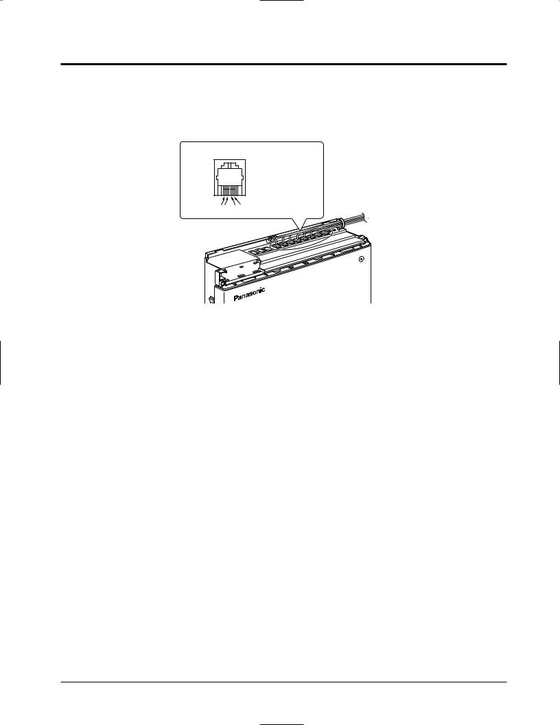
Connection
Insert the modular plugs of the telephone line cords (2 or 4-conductor wiring) into the ports (JACK 01 through 08) on the system.
View of TEL Port (Extension)
H: High
A: Tip
B: Ring
L: Low
H A B L
To extensions (JACK 01–08)
POWER
!• System extensions must be located within the same building as the KX-TA624.
Installation 2-11
2.9External Pager (Paging Equipment) Connection
One external pager (user-supplied) can be connected to the system as illustrated below.
Use an EIAJ RC-6701 A plug (2-conductor, ø 3.5 mm in diameter).
• Output impedance: 600 Ω
Maximum length of the cable
ø 0.8 mm – ø 1.3 mm: Under 10 m
Paging Port
PAGING
Speaker
Amplifier
Paging Equipment
• To adjust the sound level of the pager, use the volume control on the amplifier.
!• Paging port is at SELV.
|
• Required System Programming |
|
Section 4.2, System Programming |
|
[106] External Paging Access Tone |
|
• Feature Reference |
|
Section 3, Features |
|
Paging |
2-12 Installation
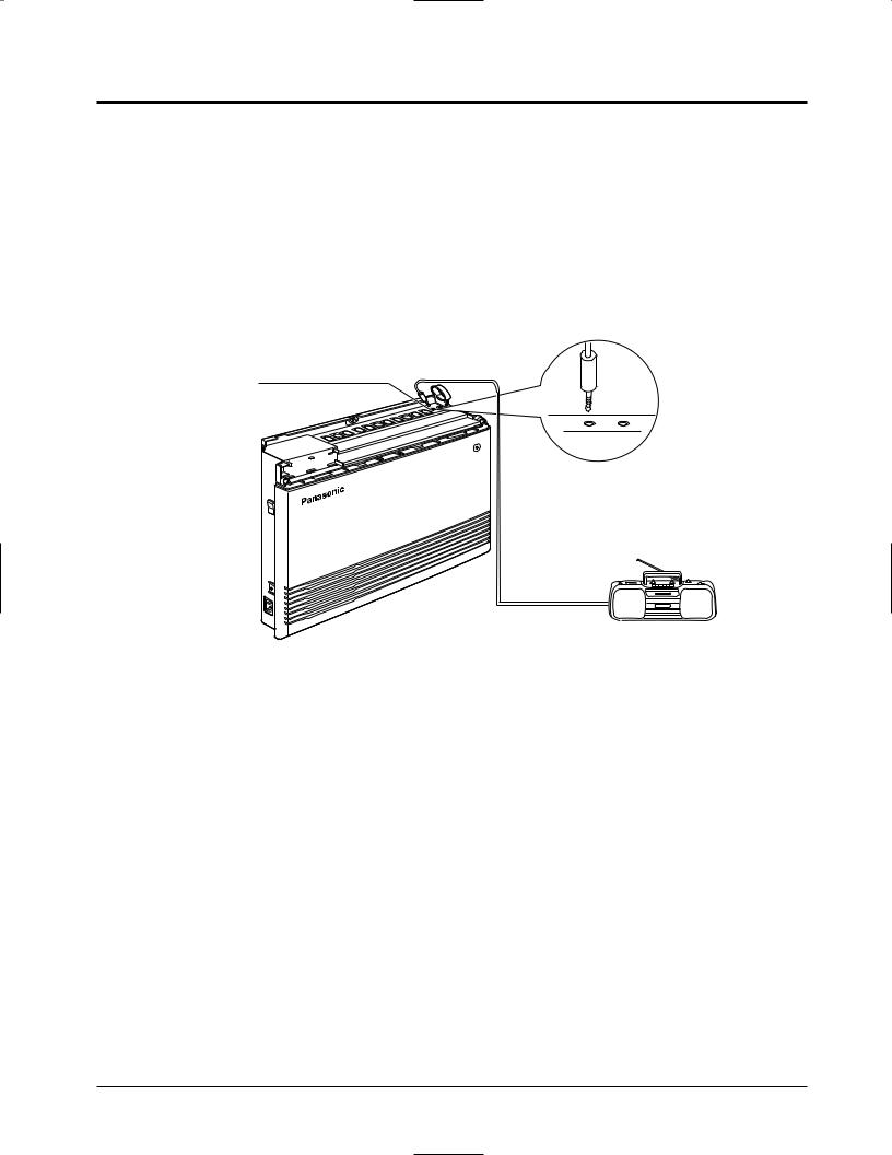
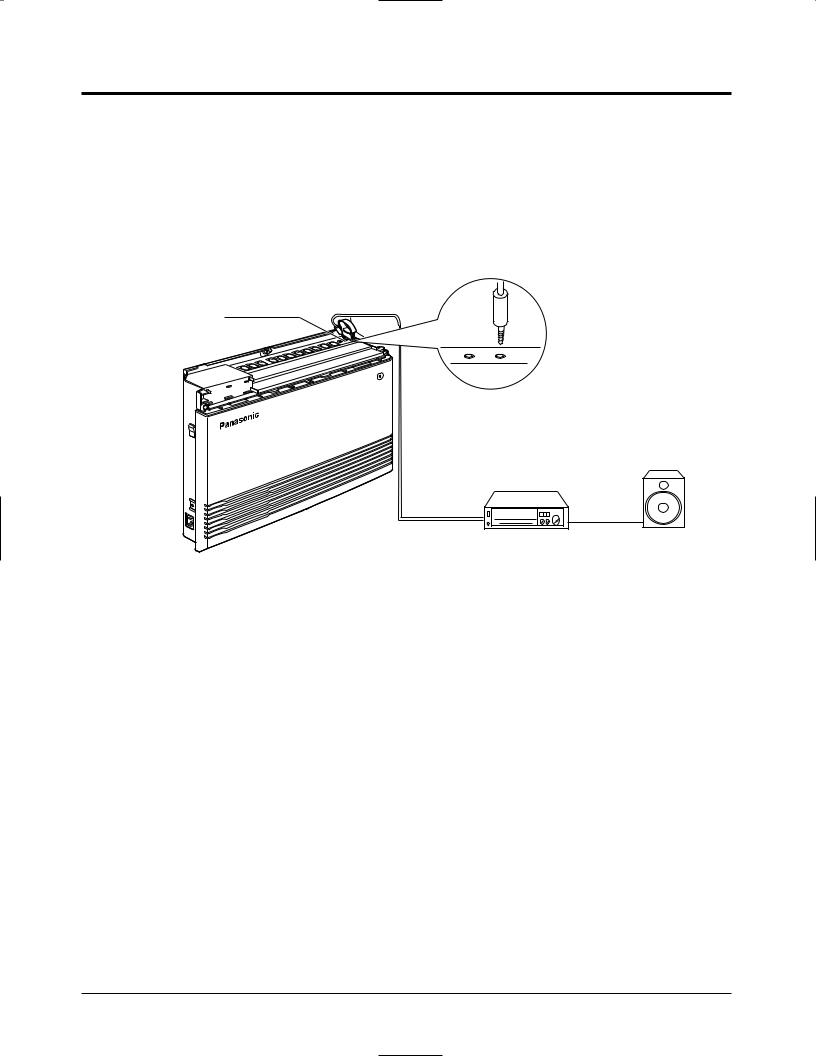
2.10External Music Connection
One music source, such as a radio (user-supplied), can be connected to the system as illustrated below.
Insert the plug to the earphone/headphone port on the external music source. Use an EIAJ RC-6701 A plug (2-conductor, ø 3.5 mm in diameter).
• Input impedance: 8 Ω
Maximum length of the cable
ø 0.8 mm – ø 1.3 mm: Under 10 m
External Music Port
External Music source
•System programming for the music sources used for Music on Hold and Background
!Music (BGM) is required.
•To adjust the sound level of the Music on Hold, use the volume control on the external music source.
•External Music port is at SELV.
|
• Required System Programming |
Section 4.2, System Programming |
|
|
[111] Hold Music Selection |
|
• Feature Reference |
|
Section 3, Features |
|
Music on Hold / Background Music (BGM) |
Installation 2-13
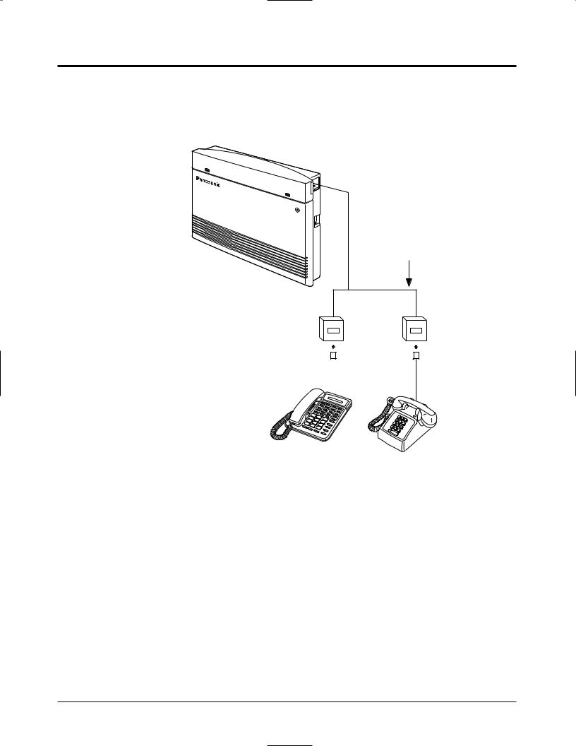
2.11Parallelled Telephone Connection
Any single line telephone can be connected in parallel with a proprietary telephone as follows.
Using a Modular T-Adaptor
2-conductor wiring cord Connect pins “A” and “B”.
4-conductor wiring cord  For a proprietary telephone:
Connect pins “A”, “B”, “H” and “L”.
|
Proprietary Telephone Single Line Telephone |
|
• Required System Programming |
Section 4.2, System Programming |
|
|
[610] Parallelled Telephone Connection |
|
• Feature Reference |
|
Section 3, Features |
|
Parallelled Telephone Connection |
2-14 Installation
Loading...