


 Loading...
Cat. No. I114E-EN-01
MX2 CompoNet Option Board
Born to drive machines
Model: 3G3AX-MX2-CRT-E
USER’S MANUAL
Notice:
OMRON products are manufactured for use according to proper procedures by a qualified operator and only for the purposes described in this manual.
The following conventions are used to indicate and classify precautions in this manual. Always heed the information provided with them. Failure to heed precautions can result in injury to people or damage to property.
OMRON Product References
All OMRON products are capitalized in this manual. The word "Unit" is also capitalized when it refers to an OMRON product, regardless of whether or not it appears in the proper name of the product.
Trademarks and Copyrights
Other product names and company names in this manual are trademarks or registered trademarks of their respective companies.
The copyright of the 3G3AX-MX2-CRT-E Option Board belongs to OMRON
Corporation.
Intended Audience
This manual is intended for the following personnel, who must also have knowledge of electrical systems (an electrical engineer or the equivalent).
•Personnel in charge of installing FA systems.
•Personnel in charge of designing FA systems.
•Personnel in charge of managing FA systems and facilities.
•Personnel in charge of maintaining FA systems.
♥ OMRON, 2010
All rights reserved. No part of this publication may be reproduced, stored in a retrieval system, or transmitted, in any form, or by any means, mechanical, electronic, photocopying, recording, or otherwise, without the prior written permission of OMRON.
No patent liability is assumed with respect to the use of the information contained herein. Moreover, because OMRON is constantly striving to improve its high-quality products, the information contained in this manual is subject to change without notice. Every precaution has been taken in the preparation of this manual. Nevertheless, OMRON assumes no responsibility for errors or omissions. Neither is any liability assumed for damages resulting from the use of the information contained in this publication.
About this Manual
This manual describes the 3G3AX-MX2-CRT-E CompoNet Option Board for
OMRON's MX2-A@ Inverter. It also describes how to install and operate the
Unit.
Please read this manual carefully so that you understand the information provided before installing or using the 3G3AX-MX2-CRT-E Option Board. Start with the precautions in the following section. They describe the operating environment and application safety measures which must be observed prior to and when using the 3G3AX-MX2-CRT-E Option Board.
Please be sure to read the related user manuals to use the 3G3AX-MX2-CRT- E Option Board safely and properly. Be sure you are using the most current version of the manual:
Manual |
Contents |
Cat No. |
|
|
|
MX2 User's Manual |
Describes the installation and operation of the MX2-A@ |
I570 |
|
Inverter |
|
|
|
|
CS/CJ Series CompoNet |
Provides an overview of CompoNet Networks, commu- |
W456 |
Master Units Operation |
nications specifications, wiring methods, and Compo- |
|
Manual |
Net Master Unit functions |
|

Warranty and Limitations of Liability
WARRANTY
OMRON's exclusive warranty is that the products are free from defects in materials and workmanship for a period of one year (or other period if specified) from date of sale by OMRON.
OMRON MAKES NO WARRANTY OR REPRESENTATION, EXPRESS OR
IMPLIED, REGARDING NONINFRINGEMENT, MERCHANTABILITY, OR FITNESS
FOR PARTICULAR PURPOSE OF THE PRODUCTS. ANY BUYER OR USER
ACKNOWLEDGES THAT THE BUYER OR USER ALONE HAS DETERMINED
THAT THE PRODUCTS WILL SUITABLY MEET THE REQUIREMENTS OF THEIR
INTENDED USE. OMRON DISCLAIMS ALL OTHER WARRANTIES, EXPRESS
OR IMPLIED.
LIMITATIONS OF LIABILITY
OMRON SHALL NOT BE RESPONSIBLE FOR SPECIAL, INDIRECT, OR CONSE-
QUENTIAL DAMAGES, LOSS OF PROFITS OR COMMERCIAL LOSS IN ANY
WAY CONNECTED WITH THE PRODUCTS, WHETHER SUCH CLAIM IS BASED
ON CONTRACT, WARRANTY, NEGLIGENCE, OR STRICT LIABILITY.
In no event shall the responsibility of OMRON for any act exceed the individual price of the product on which liability is asserted.
IN NO EVENT SHALL OMRON BE RESPONSIBLE FOR WARRANTY, REPAIR,
OR OTHER CLAIMS REGARDING THE PRODUCTS UNLESS OMRON'S ANALY-
SIS CONFIRMS THAT THE PRODUCTS WERE PROPERLY HANDLED, STORED,
INSTALLED, AND MAINTAINED AND NOT SUBJECT TO CONTAMINATION,
ABUSE, MISUSE, OR INAPPROPRIATE MODIFICATION OR REPAIR.
Application Considerations
SUITABILITY FOR USE
OMRON shall not be responsible for conformity with any standards, codes, or regulations that apply to the combination of products in the customer's application or use of the products.
At the customer's request, OMRON will provide applicable third party certification documents identifying ratings and limitations of use that apply to the products. This information by itself is not sufficient for a complete determination of the suitability of the products in combination with the end product, machine, system, or other application or use.
The following are some examples of applications for which particular attention must be given. This is not intended to be an exhaustive list of all possible uses of the products, nor is it intended to imply that the uses listed may be suitable for the products:
o Outdoor use, uses involving potential chemical contamination or electrical interference, or conditions or uses not described in this manual.
o Nuclear energy control systems, combustion systems, railroad systems, aviation systems, medical equipment, amusement machines, vehicles, safety equipment, and installations subject to separate industry or government regulations.
o Systems, machines, and equipment that could present a risk to life or property.
Please know and observe all prohibitions of use applicable to the products.
NEVER USE THE PRODUCTS FOR AN APPLICATION INVOLVING SERIOUS
RISK TO LIFE OR PROPERTY WITHOUT ENSURING THAT THE SYSTEM AS A
WHOLE HAS BEEN DESIGNED TO ADDRESS THE RISKS, AND THAT THE
OMRON PRODUCTS ARE PROPERLY RATED AND INSTALLED FOR THE
INTENDED USE WITHIN THE OVERALL EQUIPMENT OR SYSTEM.
iv

PROGRAMMABLE PRODUCTS
OMRON shall not be responsible for the user's programming of a programmable product, or any consequence thereof.
Disclaimers
CHANGE IN SPECIFICATIONS
Product specifications and accessories may be changed at any time based on improvements and other reasons. It is our practice to change model numbers when published ratings or features are changed, or when significant construction changes are made. However, some specifications of the products may be changed without any notice. When in doubt, special model numbers may be assigned to fix or establish key specifications for your application on your request. Please consult with your OMRON representative at any time to confirm actual specifications of purchased products.
DIMENSIONS AND WEIGHTS
Dimensions and weights are nominal and are not to be used for manufacturing purposes, even when tolerances are shown.
PERFORMANCE DATA
Performance data given in this manual is provided as a guide for the user in determining suitability and does not constitute a warranty. It may represent the result of OMRON's test conditions, and the users must correlate it to actual application requirements. Actual performance is subject to the OMRON Warranty and Limitations of Liability.
ERRORS AND OMISSIONS
The information in this manual has been carefully checked and is believed to be accurate; however, no responsibility is assumed for clerical, typographical, or proofreading errors, or omissions.
v
vi
|
|
Table of contents |
Safety Messages . . . . . . . . . . . . . . . . . . . . . . . . . . . . . . . . . . . . . . . . . . . . . |
. . . . . . . . . . . . . . . . ix |
|
1 |
Hazardous High Voltage . . . . . . . . . . . . . . . . . . . . . . . . . . . . . . . . . . . . . . . . . . . . . . |
. . . . . . . . . . . . . . . . . . . ix |
2 General Precautions - Read These First! . . . . . . . . . . . . . . . . . . . . . . . . . . . . . . . . . . |
. . . . . . . . . . . . . . . . . . . x |
|
3 |
Installation Precautions . . . . . . . . . . . . . . . . . . . . . . . . . . . . . . . . . . . . . . . . . . . . . . . . |
. . . . . . . . . . . . . . . . . . . xi |
4 |
Configuration Precautions . . . . . . . . . . . . . . . . . . . . . . . . . . . . . . . . . . . . . . . . . . . . . |
. . . . . . . . . . . . . . . . . . . xi |
5 |
Application Precautions . . . . . . . . . . . . . . . . . . . . . . . . . . . . . . . . . . . . . . . . . . . . . . . |
. . . . . . . . . . . . . . . . . . . xii |
6 |
Operating Environment Precautions . . . . . . . . . . . . . . . . . . . . . . . . . . . . . . . . . . . . . . |
. . . . . . . . . . . . . . . . . . . xiii |
7 Handling, Storage and Disposal . . . . . . . . . . . . . . . . . . . . . . . . . . . . . . . . . . . . . . . . . |
. . . . . . . . . . . . . . . . . . . xiii |
|
8 Compliance with EC Directives . . . . . . . . . . . . . . . . . . . . . . . . . . . . . . . . . . . . . . . . . |
. . . . . . . . . . . . . . . . . . . xiii |
|
SECTION 1 |
|
|
Getting Started . . . . . . . . . . . . . . . . . . . . . . . . . . . . . . . . . . . . . . . . . . . . . |
. . . . . . . . . . . . . . . . 1 |
|
1-1 |
Introduction . . . . . . . . . . . . . . . . . . . . . . . . . . . . . . . . . . . . . . . . . . . . . . . . . . . . . . . . |
. . . . . . . . . . . . . . . . . . . 1 |
1-2 |
Option Board Specifications . . . . . . . . . . . . . . . . . . . . . . . . . . . . . . . . . . . . . . . . . . . . |
. . . . . . . . . . . . . . . . . . . 3 |
1-3 |
Introduction to CompoNet . . . . . . . . . . . . . . . . . . . . . . . . . . . . . . . . . . . . . . . . . . . . . |
. . . . . . . . . . . . . . . . . . . 4 |
SECTION 2 |
|
|
Option Board Mounting and Installation . . . . . . . . . . . . . . . . . . . . . . . . |
. . . . . . . . . . . . . . . . 7 |
|
2-1 Orientation to Option Board Features . . . . . . . . . . . . . . . . . . . . . . . . . . . . . . . . . . . . |
. . . . . . . . . . . . . . . . . . . 7 |
|
2-2 |
Basic System Description . . . . . . . . . . . . . . . . . . . . . . . . . . . . . . . . . . . . . . . . . . . . . . |
. . . . . . . . . . . . . . . . . . . 9 |
2-3 |
Step-by-Step Basic Installation . . . . . . . . . . . . . . . . . . . . . . . . . . . . . . . . . . . . . . . . . |
. . . . . . . . . . . . . . . . . . . 10 |
SECTION 3 |
|
|
Configuring Drive Parameters and Option Board . . . . . . . . . . . . . . . . . |
. . . . . . . . . . . . . . . . 15 |
|
3-1 Installation of EDS files . . . . . . . . . . . . . . . . . . . . . . . . . . . . . . . . . . . . . . . . . . . . . . . |
. . . . . . . . . . . . . . . . . . . 15 |
|
3-2 Configuring the Option Board . . . . . . . . . . . . . . . . . . . . . . . . . . . . . . . . . . . . . . . . . . |
. . . . . . . . . . . . . . . . . . . 15 |
|
3-3 |
Configuring the Network . . . . . . . . . . . . . . . . . . . . . . . . . . . . . . . . . . . . . . . . . . . . . . |
. . . . . . . . . . . . . . . . . . . 18 |
3-4 |
Registration table . . . . . . . . . . . . . . . . . . . . . . . . . . . . . . . . . . . . . . . . . . . . . . . . . . . . |
. . . . . . . . . . . . . . . . . . . 19 |
SECTION 4 |
|
|
Operations and Monitoring . . . . . . . . . . . . . . . . . . . . . . . . . . . . . . . . . . . |
. . . . . . . . . . . . . . . . 21 |
|
4-1 |
Setting up inverter . . . . . . . . . . . . . . . . . . . . . . . . . . . . . . . . . . . . . . . . . . . . . . . . . . . |
. . . . . . . . . . . . . . . . . . . 21 |
4-2 |
Operating the Motor . . . . . . . . . . . . . . . . . . . . . . . . . . . . . . . . . . . . . . . . . . . . . . . . . . |
. . . . . . . . . . . . . . . . . . . 22 |
4-3 |
Overriding Inverter inputs . . . . . . . . . . . . . . . . . . . . . . . . . . . . . . . . . . . . . . . . . . . . . |
. . . . . . . . . . . . . . . . . . . 23 |
4-4 |
Controlling Inverter Torque . . . . . . . . . . . . . . . . . . . . . . . . . . . . . . . . . . . . . . . . . . . . |
. . . . . . . . . . . . . . . . . . . 23 |
4-5 |
Faults and Trips . . . . . . . . . . . . . . . . . . . . . . . . . . . . . . . . . . . . . . . . . . . . . . . . . . . . . |
. . . . . . . . . . . . . . . . . . . 25 |
4-6 |
Accessing Parameters . . . . . . . . . . . . . . . . . . . . . . . . . . . . . . . . . . . . . . . . . . . . . . . . . |
. . . . . . . . . . . . . . . . . . . 26 |
4-7 |
Flexible Format . . . . . . . . . . . . . . . . . . . . . . . . . . . . . . . . . . . . . . . . . . . . . . . . . . . . . . |
. . . . . . . . . . . . . . . . . . . 26 |
4-8 Limitations Caused by Inverter Mode and Rating Selection . . . . . . . . . . . . . . . . . . . |
. . . . . . . . . . . . . . . . . . . 29 |
|
SECTION 5 |
|
|
Troubleshooting and Maintenance . . . . . . . . . . . . . . . . . . . . . . . . . . . . . |
. . . . . . . . . . . . . . . . 31 |
|
5-1 Troubleshooting Using the LED Indicators . . . . . . . . . . . . . . . . . . . . . . . . . . . . . . . . |
. . . . . . . . . . . . . . . . . . . 31 |
|
5-2 Other Error Causes and Error Procedures . . . . . . . . . . . . . . . . . . . . . . . . . . . . . . . . . |
. . . . . . . . . . . . . . . . . . . 35 |
|
5-3 |
Maintenance and Inspection . . . . . . . . . . . . . . . . . . . . . . . . . . . . . . . . . . . . . . . . . . . . |
. . . . . . . . . . . . . . . . . . . 36 |
APPENDIX A
Glossary . . . . . . . . . . . . . . . . . . . . . . . . . . . . . . . . . . . . . . . . . . . . . . . . . . . . . . . . . . . . . . . . . . . 39
vii

|
Table of contents |
APPENDIX B |
|
Assembly Specification . . . . . . . . . . . . . . . . . . . . . . . . . . . . . . . . . . . . . . . . . . . . |
. . . . . . . . . . . 41 |
B-1 Basic Speed Control IO (20/70) . . . . . . . . . . . . . . . . . . . . . . . . . . . . . . . . . . . . . . . . . . . . . . . |
. . . . . . . . . . . . . 41 |
B-2 Extended Speed Control IO (21/71) . . . . . . . . . . . . . . . . . . . . . . . . . . . . . . . . . . . . . . . . . . . . |
. . . . . . . . . . . . . 42 |
B-3 Extended Speed and Torque Control IO (123/173) . . . . . . . . . . . . . . . . . . . . . . . . . . . . . . . . |
. . . . . . . . . . . . . 43 |
B-4 Special IO (100/150) . . . . . . . . . . . . . . . . . . . . . . . . . . . . . . . . . . . . . . . . . . . . . . . . . . . . . . . . |
. . . . . . . . . . . . . 45 |
B-5 Extended Control IO (101/151/153) . . . . . . . . . . . . . . . . . . . . . . . . . . . . . . . . . . . . . . . . . . . . |
. . . . . . . . . . . . . 46 |
B-6 Extended Speed and Acceleration Control IO (110/111) . . . . . . . . . . . . . . . . . . . . . . . . . . . . |
. . . . . . . . . . . . . 49 |
APPENDIX C |
|
General Object Specification . . . . . . . . . . . . . . . . . . . . . . . . . . . . . . . . . . . . . . . |
. . . . . . . . . . . 53 |
C-1 Identity Object (Class 0x01) . . . . . . . . . . . . . . . . . . . . . . . . . . . . . . . . . . . . . . . . . . . . . . . . . . |
. . . . . . . . . . . . . 53 |
C-2 Message Router Object (Class 0x02) . . . . . . . . . . . . . . . . . . . . . . . . . . . . . . . . . . . . . . . . . . . |
. . . . . . . . . . . . . 54 |
C-3 Assembly Object (Class 0x04) . . . . . . . . . . . . . . . . . . . . . . . . . . . . . . . . . . . . . . . . . . . . . . . . |
. . . . . . . . . . . . . 55 |
C-4 Connection Object (Class 0x05) . . . . . . . . . . . . . . . . . . . . . . . . . . . . . . . . . . . . . . . . . . . . . . . |
. . . . . . . . . . . . . 56 |
C-5 Discrete Input Point Object (Class 0x08) . . . . . . . . . . . . . . . . . . . . . . . . . . . . . . . . . . . . . . . . |
. . . . . . . . . . . . . 57 |
C-6 Discrete Output Point Object (Class 0x09) . . . . . . . . . . . . . . . . . . . . . . . . . . . . . . . . . . . . . . . |
. . . . . . . . . . . . . 57 |
C-7 Unit Parameter Object (Class 0x94) . . . . . . . . . . . . . . . . . . . . . . . . . . . . . . . . . . . . . . . . . . . . |
. . . . . . . . . . . . . 58 |
C-8 CompoNet Link Object (Class 0xF7) . . . . . . . . . . . . . . . . . . . . . . . . . . . . . . . . . . . . . . . . . . . |
. . . . . . . . . . . . . 58 |
APPENDIX D |
|
AC Drive Object Specification . . . . . . . . . . . . . . . . . . . . . . . . . . . . . . . . . . . . . . |
. . . . . . . . . . . 59 |
D-1 Motor Data Object (Class 0x28) . . . . . . . . . . . . . . . . . . . . . . . . . . . . . . . . . . . . . . . . . . . . . . . |
. . . . . . . . . . . . . 59 |
D-2 Control Supervisor Object (Class 0x29) . . . . . . . . . . . . . . . . . . . . . . . . . . . . . . . . . . . . . . . . . |
. . . . . . . . . . . . . 60 |
D-3 AC/DC Drive Object (Class 0x2A) . . . . . . . . . . . . . . . . . . . . . . . . . . . . . . . . . . . . . . . . . . . . . |
. . . . . . . . . . . . . 63 |
APPENDIX E |
|
CompoNet Explicit Messages . . . . . . . . . . . . . . . . . . . . . . . . . . . . . . . . . . . . . . . |
. . . . . . . . . . . 65 |
E-1 Basic Format of Explicit Messages . . . . . . . . . . . . . . . . . . . . . . . . . . . . . . . . . . . . . . . . . . . . . |
. . . . . . . . . . . . . 65 |
E-2 Function Code Object (Class 0x65) . . . . . . . . . . . . . . . . . . . . . . . . . . . . . . . . . . . . . . . . . . . . |
. . . . . . . . . . . . . 67 |
E-3 Modbus Register Object (Class 0x64) . . . . . . . . . . . . . . . . . . . . . . . . . . . . . . . . . . . . . . . . . . |
. . . . . . . . . . . . . 69 |
E-4 Explicit Message Error Codes . . . . . . . . . . . . . . . . . . . . . . . . . . . . . . . . . . . . . . . . . . . . . . . . . |
. . . . . . . . . . . . . 71 |
APPENDIX F |
|
Flexible Format . . . . . . . . . . . . . . . . . . . . . . . . . . . . . . . . . . . . . . . . . . . . . . . . . . |
. . . . . . . . . . . 73 |
Table index . . . . . . . . . . . . . . . . . . . . . . . . . . . . . . . . . . . . . . . . . . . . . . . . . . . . . . |
. . . . . . . . . . . 75 |
Revision history . . . . . . . . . . . . . . . . . . . . . . . . . . . . . . . . . . . . . . . . . . . . |
. . . . . . . . . 77 |
viii
Safety Messages
For the best results with the MX2-A@ Inverter, carefully read this manual and all of the warning labels attached to the Inverter before installing and operating it, and follow the instructions exactly. Keep this manual handy for quick reference.
Definitions and Symbols
A safety instruction (message) includes a "Safety Alert Symbol" and a signal word or phrase such as WARNING or CAUTION. Each signal word has the following meaning:
!HIGH VOLTAGE Indicates a potentially hazardous situation which, if not avoided, could result in electric shock. It calls your attention to items or operations that could be dangerous to you and other persons operating this equipment.
Read the message and follow the instructions carefully.
!WARNING Indicates a potentially hazardous situation which, if not avoided, could result in death or serious injury. Additionally, there may be severe property damage.
!Caution Indicates a potentially hazardous situation, which, if not avoided, may result in minor or moderate injury, or property damage.
Step 1 Indicates a step in a series of action steps required to accomplish a goal. The number of the step will be contained in the step symbol.
Note Notes indicate an area or subject of special merit, emphasizing either the product's capability or common errors in operation or maintenance.
Tip Tips give a special instruction that can save time or provide other benefits while installing or using the product. The tip calls attention to an idea that may not be obvious if you are a first-time user of the product.
1 Hazardous High Voltage
!HIGH VOLTAGE Motor control equipment and electronic controllers are connected to hazardous line voltages. When servicing drives and electronic controllers, there may be exposed components with housing or protrusions at or above line potential. Extreme care should be taken to protect against shock.
Stand on an insulating pad and make it a habit to use only one hand when checking components. Always work with another person in case an emergency occurs. Disconnect power before checking controllers or performing maintenance. Be sure equipment is properly grounded. Wear safety glasses whenever working on electronic controllers or rotating machinery.
ix

General Precautions - Read These First!
2 General Precautions - Read These First!
!WARNING Failure to read and understand the information provided in this manual may result in personal injury or death, damage to the product, or product failure. Please read each section in its entirety and be sure you understand the information provided in the section and related sections before attempting any of the procedures or operations given.
!WARNING This equipment should be installed, adjusted, and serviced by qualified electrical maintenance personnel familiar with the construction and operation of the equipment and the hazards involved. Failure to observe this precaution could result in bodily injury.
!WARNING Wiring, maintenance or inspection must be performed by authorized personnel. Not doing so may result in electrical shock or fire.
!WARNING Hazard of electrical shock! Disconnect incoming power before working on the OMRON 3G3AX-MX2-CRT-E CompoNet Option Board or the MX2-A@ Inverter.
!HIGH VOLTAGE Turn the power supply OFF and wait for the time specified on the Option Board front cover before performing wiring, maintenance or inspection. Not doing so may result in electrical shock.
The OMRON 3G3AX-MX2-CRT-E CompoNet Option Board is attached to an MX2-A@ Inverter. Dangerous voltage exists until the MX2-A@ Inverter power light is OFF.
!HIGH VOLTAGE Do not touch the conductive parts such as the internal PCB, terminals or connector while power is being supplied. Doing so may result in electrical shock.
!WARNING Do not attempt to take an Option Board apart or touch any internal parts while the power is being supplied. Doing so may result in electric shock.
!WARNING Do not attempt to disassemble, repair, or modify an Option Board. Any attempt to do so may result in malfunction, fire, or electric shock.
!WARNING Provide emergency stop circuits, interlock circuits, limit circuits and similar safety measures in external circuits (NOT in the Option Board). This ensures safety in the system if an abnormality occurs due to malfunction of the Option Board or another external factor affecting the Option Board operation. Not doing so may result in serious accidents.
!WARNING Fail-safe measures must be taken by the customer to ensure safety in the event of incorrect, missing, or abnormal signals caused by broken signal lines, momentary power interruptions, or other causes. Not doing so may result in serious accidents.
!Caution Do not touch the Inverter during power on, and immediately after power off. Hot surface may cause injury.
x
Installation Precautions
!Caution The product will be used to control an adjustable speed drive connected to high voltage sources and rotating machinery that is inherently dangerous if not operated safely. Interlock all energy sources, hazardous locations, and guards in order to restrict the exposure of personnel to hazards. The adjustable speed drive may start the motor without warning. Signs on the equipment installation must be posted to this effect. A familiarity with auto-restart settings is a requirement when controlling adjustable speed drives. Failure of external or ancillary components may cause intermittent system operation, i.e., the system may start the motor without warning or may not stop on command. Improperly designed or improperly installed system interlocks and permissives may render a motor unable to start or stop on command.
3 Installation Precautions
!WARNING Always connect the grounding cable to one of the ground terminals of the MX2-A@ Inverter. Failure to abide could lead to serious or possibly fatal injury.
!Caution Failure to observe these precautions could lead to faulty operation of the Option Board or the Inverter, or could damage either of the two. Always read these precautions.
•Install external breakers and take other safety measures against short-cir- cuits in external wiring. Not observing this may result in burning.
•Be sure that all cable connector screws are tightened to the torque specified in the relevant manuals. Incorrect tightening torque may result in malfunction.
•Do not allow metal clippings to enter either Option Board or Inverter when wiring or installing the unit.
•Follow the network configuration and wiring instructions provided in the CompoNet Master Units Operation Manual (Cat. No. W456):
•Wire the CompoNet cables and connectors correctly. Incorrect wiring may result in burning.
•Be sure that the network connectors are clicked into place correctly. Improper latching may result in malfunction.
•Always connect a Terminating Resistor at the prescribed locations of the CompoNet network to ensure the quality of the transmission path Do not apply termination anywhere else.
•Be sure that the Option Board is mounted correctly. Improper mounting may result in malfunction.
•Disconnect the grounding cable when performing withstand-voltage tests. Not disconnecting the grounding cable may result in burning.
4 Configuration Precautions
!Caution Failure to observe these precautions could lead to unexpected operation of the Option Board or the Inverter. Always read these precautions.
•Check the network related Inverter settings regarding CompoNet node address and CompoNet remote I/O allocation. Not doing so may result in unexpected operation.
•When replacing an Inverter be sure that all Inverter settings of the Inverter being replaced are restored to the replacement.
xi

Application Precautions
•When replacing an Option Board be sure that the setting of the rotary switches of the Option Board being replaced are restored to the replacement.
•Restoring parameters stored in the remote operator also restores the CompoNet node address. Always check the node address and other network related Inverter settings after restore.
5 Application Precautions
!WARNING Before using the product under conditions which are not described in the manual or applying the product to nuclear control systems, railroad systems, aviation systems, vehicles, combustion systems, medical equipment, amusement machines, safety equipment, and other systems, machines, and equipment that may have a serious influence on lives and property if used improperly, consult your OMRON representative.
!WARNING It is extremely important that the Unit is used for its specified purpose and under the specified conditions, especially in applications that can directly or indirectly affect human life. You must consult your OMRON representative before using it in a system in the above-mentioned applications.
!WARNING Failure to observe these precautions could lead to serious or possibly fatal injury. Always read these precautions.
•Check any user program in the system that acts as a CompoNet Master before actually running it. Not checking the program may result in unexpected operation.
•For safe operation clear the run command via CompoNet as soon as a trip condition is detected.
•In the event the Inverter is in a Trip state, be sure to investigate the cause of this Trip state thoroughly before clearing the Trip. Not checking the cause may result in unexpected operation.
!Caution Failure to observe these precautions could lead to faulty operation of the Option Board or the Inverter, or could damage to either of the two. Always read these precautions.
•Check the Inverter settings for proper Inverter behaviour before actually operating the Inverter remotely via the CompoNet network.
•Check the Inverter's EzSQ program and its interaction with the CompoNet Master before actually running it on the Inverter. Not checking the program may result in unexpected operation.
•Confirm that no adverse effect will occur at the moment the CompoNet Master stops communicating with the Inverter or at the moment the CompoNet Master has not yet started communicating to the Inverter.
•Confirm that no adverse effect will occur in the Inverter before force-set- ting/force-resetting any bit in the system that acts as a CompoNet Master.
xii

Operating Environment Precautions
6 Operating Environment Precautions
!Caution Do not operate the MX2-A@ Inverter with a mounted 3G3AX-MX2-CRT-E Option Board in the following locations (doing so may result in malfunction, electric shock or burning):
•Locations subject to direct sunlight
•Locations subject to temperatures or humidity outside the range specified in the specifications
•Locations subject to condensation as the result of severe changes in temperature
•Locations subject to corrosive or flammable gases
•Locations subject to dust (especially iron dust) or salts
•Locations subject to exposure to water, oil, or chemicals
•Locations subject to shock or vibration
!Caution Take appropriate and sufficient countermeasures when installing systems in the following locations (doing so may result in malfunction):
•Locations subject to static electricity or other forms of noise
•Locations subject to strong electromagnetic fields
•Locations subject to possible exposure to radioactivity
•Locations close to power supplies
!Caution The operating environment of the MX2-A@ Inverter with a mounted 3G3AX-MX2-CRT-E Option Board can have a large effect on the longevity and reliability of the system. Improper operating environments can lead to malfunction, failure, and other unforeseeable problems with the system. Make sure that the operating environment is within the specified conditions at installation and remains within the specified conditions during the life of the system.
7 Handling, Storage and Disposal
!Caution Failure to observe these precautions could lead to faulty operation of or damage to the Option Board. Always read these precautions.
•Before touching the Option Board or Inverter, be sure to first touch a grounded metallic object in order to discharge any static built-up. Not doing so may result in malfunction or damage.
•When transporting or storing the 3G3AX-MX2-CRT-E Option Board, keep the product within the specified storage temperature range.
!Caution Never dispose electrical components by incineration. Contact your state environmental agency for details on disposal of electrical components and packaging in your area.
8 Compliance with EC Directives
This product complies with EC Directives when mounted to an MX2-A@
Inverter with the grounding cable connected.
xiii

Compliance with EC Directives
xiv
SECTION 1
Getting Started
1-1 Introduction
1-1-1 Main Features
|
The 3G3AX-MX2-CRT-E allows controlling, monitoring and parameterization |
|
of an MX2-A@ Inverter via a CompoNet network. The 3G3AX-MX2-CRT-E |
|
serves as a gateway that passes communicated register values from the |
|
CompoNet network to the MX2-A@ Inverter and vice versa. The |
|
3G3AX-MX2-CRT-E adheres to the CompoNet / CIP AC Drive profile. |
|
The following functions are available via CompoNet communication by install- |
|
ing the 3G3AX-MX2-CRT-E: |
Cyclic Data Exchange |
The CompoNet Master and 3G3AX-MX2-CRT-E can exchange data via a |
|
CompoNet Remote I/O connection: |
|
• Output data (from CompoNet Master to 3G3AX-MX2-CRT-E): |
|
E.g. Run/stop, Reference frequency and Fault reset. |
|
• Input data (from 3G3AX-MX2-CRT-E to CompoNet Master): |
|
E.g. Inverter status, Output frequency and Output current, etc. |
Inverter Parameter Access |
The CompoNet Master can read and write parameter data via the |
|
3G3AX-MX2-CRT-E using the explicit message communication. |
|
The inverter parameters are accessible in multiple ways: |
|
• Access based on Function code |
|
• Access based on the Modbus register address |
|
Several AC Drive profile attributes can also be accessed using the explicit |
|
message mechanism. |
Simplified Start-up |
The 3G3AX-MX2-CRT-E can be set up easily, just by wiring the Unit, setting |
|
the CompoNet node address by either the rotary switches or by setting |
|
inverter parameter (P190) and the default connection path (P046) and restart- |
|
ing the unit. The Unit’s configuration is read automatically when the power is |
|
turned ON or after a reset. It is not necessary to make any settings with a spe- |
|
cial Programming Device. |
Simplified Replacement |
All parameters required by the 3G3AX-MX2-CRT-E are stored in the MX2-A@ |
|
Inverter. The 3G3AX-MX2-CRT-E can be replaced, requiring no re-configura- |
|
tion. |
Automatic Baud Rate |
The 3G3AX-MX2-CRT-E automatically detects the Master’s communication |
Recognition |
baud rate, and no user configuration is required. |
1

Introduction |
Section 1-1 |
1-1-2 Inverter Support
The 3G3AX-MX2-CRT-E Option Board supports the MX2-A@ Inverter with minimum revision of AAAA. An MX2-A@ Inverter that supports the 3G3AX-MX2-CRT-E Option Board can be recognised from the Inverter type label. Please check that your Inverter type label displays revision characters in the bottom right corner where the is displayed in this illustration.
@@@@
Please note if these characters are absent, your Inverter does not support the 3G3AX-MX2-CRT-E, so please contact your local OMRON representative.
1-1-3 Inverter Safety (ISO 13849-1)
An MX2-A@ Inverter provides a Gate Suppress function to perform a safe stop according to the EN60204-1, stop category 0. The 3G3AX-MX2-CRT-E Option Board has been designed not to interfere with this safety function.
Note The 3G3AX-MX2-CRT-E is not a safety device and does not implement any safety protocols.
2

Option Board Specifications Section 1-2
1-2 |
Option Board Specifications |
|||
Table 1 |
Option Board Specification |
|
||
|
|
|
|
|
|
|
Item |
Specification |
|
|
|
|
||
Installation |
Unit type |
MX2 Series Option Board |
||
|
|
|||
Weight |
170g (typical) |
|||
|
Model |
3G3AX-MX2-CRT-E |
||
|
Dimensions (W x H x D) |
68 x 58 x 45 mm |
||
|
|
|
||
|
Ambient operating temperature |
-10 to 55°C (no icing or condensation) |
||
|
|
|
||
Environment |
Ambient operating humidity |
20 to 90%RH |
||
|
|
|
||
Ambient storage temperature |
-20 to 65°C (no icing or condensation) |
|||
|
||||
|
|
|
||
|
Vibration resistance |
5.9m/s2 (0.6G) at 10…55Hz |
||
|
|
|
||
|
Dielectric strength |
500 VAC (between isolated circuits) |
||
|
|
|
||
|
Conformance to EMC and Electrical |
EN61800-3: 2004 (2004/108/EC) Second environment, Category C3 |
||
|
safety standards |
|
||
|
EN61800-5-1: 2007 (2006/95/EC) SELV |
|||
|
|
|
||
|
|
|
||
|
Enclosure rating |
IP 20 |
||
|
|
|
||
Interface |
Communications |
CompoNet |
||
protocol |
|
|||
|
|
|||
|
|
|
||
|
Slave Type |
Word Slave Unit (Mixed) |
||
|
|
|
||
CompoNet |
Certification |
CompoNet Conformance Tested |
||
|
|
|
||
CompoNet Profile |
AC Drive (0x02) |
|||
|
||||
|
|
|
||
|
Node Address |
0 to 63, set with inverter parameter P190 or the rotary switches. |
||
|
|
|
||
|
Baud rates supported |
4 Mbps, 3 Mbps, 1.5 Mbps, 93.75 kbps. Automatically detecting baud rate of |
||
|
|
|
Master Unit |
|
|
|
|
||
Configuration |
Default Connection path |
Supported, set with inverter parameter P046 |
||
|
|
|
||
Supported Assemblies |
Basic Remote IO (Output assembly 20, Input assembly 70) |
|||
|
||||
|
|
|
Extended Speed IO (21, 71) |
|
|
|
|
Extended Speed and Torque Control (123, 173) |
|
|
|
|
Special IO (100, 150) |
|
CompoNet |
|
|
Extended Control IO (101, 151) |
|
|
|
Extended Control IO and Multi function IO monitor (101, 153) |
||
|
|
|
||
|
|
|
Flexible Format (139, 159) |
|
|
|
|
Extended Speed and Acceleration Control (110, 111) |
|
|
|
|
||
|
EDS file |
Depending on the MX2@ inverter model (see below) |
||
Note In case the 3G3AX-MX2-DRT-E is connected to the MX2 Inverter, it is not supported to connect any external devices to the RS485(Modbus) interface and the RJ45 port (Optional operator port) of the inverter.
The required EDS file for the option board depends on the model of the
MX2-A@ inverter.
Table 2 Device List
MX2-A@ Model name |
Name of EDS file |
Product |
|
|
Code |
|
|
|
MX2-AB001-E |
3G3AX-MX2-CRT-AB001_A2001-E.eds |
1800 |
|
|
|
MX2-A2001-E |
|
|
|
|
|
MX2-AB002-E |
3G3AX-MX2-CRT-AB002_A2002-E.eds |
1801 |
|
|
|
MX2-A2002-E |
|
|
|
|
|
MX2-AB004-E |
3G3AX-MX2-CRT-AB004_A2004-E.eds |
1802 |
|
|
|
MX2-A2004-E |
|
|
|
|
|
MX2-AB007-E |
3G3AX-MX2-CRT-AB007_A2007-E.eds |
1804 |
|
|
|
MX2-A2007-E |
|
|
|
|
|
3

Introduction to CompoNet |
Section 1-3 |
||
|
Table 2 Device List (continued) |
|
|
|
|
|
|
|
MX2-A@ Model name |
Name of EDS file |
Product |
|
|
|
Code |
|
MX2-AB015-E |
3G3AX-MX2-CRT-AB015_A2015-E.eds |
1806 |
|
|
|
|
|
MX2-A2015-E |
|
|
|
|
|
|
|
MX2-AB022-E |
3G3AX-MX2-CRT-AB022_A2022-E.eds |
1807 |
|
|
|
|
|
MX2-A2022-E |
|
|
|
|
|
|
|
MX2-A2037-E |
3G3AX-MX2-CRT-A2037-E.eds |
1809 |
|
|
|
|
|
MX2-A2055-E |
3G3AX-MX2-CRT-A2055-E.eds |
1811 |
|
|
|
|
|
MX2-A2075-E |
3G3AX-MX2-CRT-A2075-E.eds |
1812 |
|
|
|
|
|
MX2-A2110-E |
3G3AX-MX2-CRT-A2110-E.eds |
1813 |
|
|
|
|
|
MX2-A2150-E |
3G3AX-MX2-CRT-A2150-E.eds |
1814 |
|
|
|
|
|
MX2-A4004-E |
3G3AX-MX2-CRT-A4004-E.eds |
1822 |
|
|
|
|
|
MX2-A4007-E |
3G3AX-MX2-CRT-A4007-E.eds |
1824 |
|
|
|
|
|
MX2-A4015-E |
3G3AX-MX2-CRT-A4015-E.eds |
1826 |
|
|
|
|
|
MX2-A4022-E |
3G3AX-MX2-CRT-A4022-E.eds |
1827 |
|
|
|
|
|
MX2-A4030-E |
3G3AX-MX2-CRT-A4030-E.eds |
1828 |
|
|
|
|
|
MX2-A4040-E |
3G3AX-MX2-CRT-A4040-E.eds |
1830 |
|
|
|
|
|
MX2-A4055-E |
3G3AX-MX2-CRT-A4055-E.eds |
1831 |
|
|
|
|
|
MX2-A4075-E |
3G3AX-MX2-CRT-A4075-E.eds |
1832 |
|
|
|
|
1-3 Introduction to CompoNet
1-3-1 Overview of CompoNet
CompoNet Networks feature easy operation and installation in a componentlevel network connecting PLCs and on-site I/O. The PLC and CompoNet Slave Units cyclically exchange I/O information through a CompoNet Master Unit, refreshing I/O in sync with the PLC scan. CompoNet (just like DeviceNet) is a member of a family of networks that implements the Common Industrial Protocol (CIP) at its upper layers.
Two types of communications are supported to provide a single point of connection for both control and configuration:
1.Time-critical control remote I/O communications that automatically transfer between the Master Unit/CPU Unit and the remote Slave Units, and
2.Explicit message communications that read/write messages, control operation, or perform other functions to the Slave Units. Message communications are achieved by executing specific instructions from the program in the CPU Unit to which the Master Unit is mounted.
1-3-2 CompoNet Slave Unit Groups
|
CompoNet Slave Units can be classified into the following groups: |
Word Slave Units |
Word Slave Units are Slave Units that are allocated units of 16 bits (i.e., 1 |
|
word) in I/O memory of the CPU Unit. |
Bit Slave Units |
Bit Slave Units are Slave Units that are allocated units of 2 bits in I/O memory |
|
of the CPU Unit. Bit Slave Units provide 2 or 4 digital contact I/O points and |
|
have Standard or Sheathed Flat Cable already connected. |
Repeater Units |
Units that can be used to expand the network by extending trunk lines or |
|
branching |
4

Introduction to CompoNet |
Section 1-3 |
1-3-3 What is the AC Drive profile
Within CompoNet/CIP standard, multiple device profiles have been defined.
Therefore the devices which adhere to a certain device profile are compatible.
The AC Drive device profile (profile code 0x02) supplements the CompoNet/ CIP standard. It defines a unified behaviour and technique to access Inverter and drive device data. All drives supporting the AC Drive profile respond the same way to control instructions.
5

Introduction to CompoNet |
Section 1-3 |
6
SECTION 2
Option Board Mounting and Installation
2-1 Orientation to Option Board Features
2-1-1 Unpacking and Inspection
Take a few moments to unpack your new 3G3AX-MX2-CRT-E Option Board and perform these steps:
1.Look for any damage that may have occurred during transportation.
2.Verify the contents of the box:
Option Board with Instruction Sheet Warning Labels
Grounding Cable
3. Inspect the markings on the Option Board. Make sure it matches the product part number you ordered.
7
Orientation to Option Board Features |
Section 2-1 |
2-1-2 Main Physical Features
underside
A 


 F
F
B 


 G
G
C
D
E
A - Option board connector
B - LED indicators (MS, NS)
C - Warning label
D - Fieldbus connector
E - Grounding cable
F - Housing
G - Mounting screw
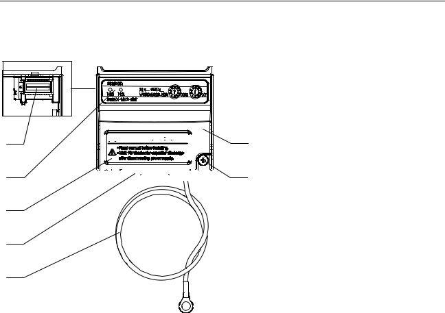
The LED indicators (B) allow easy diagnosis. An attached grounding cable (E) is sized to reach the ground terminals on all MX2-A@ Inverter models. A feature in the housing (F) will retain the mounting screw (G) when the Option Board is not mounted to the Inverter. The orientation of the Fieldbus connector (D) allows unstrained connection and removal of the CompoNet connector. Please pay special attention to the Option Board connector: It must be properly connected with the Inverter when the Option Board is mounted.
2-1-3 LED Indicators
The LED indicators on the front indicate the operational mode and status of the Option Board and the network.
Table 3 LED Indicators
Indicator |
Colour |
Status |
Meaning |
|
|
|
|
MS |
|
Not lit |
• Power is not supplied to the Option Board |
(Module status) |
|
|
• Option Board is being reset |
|
|
|
|
|
Green |
Lit |
Normal operation |
|
|
|
|
|
Red |
Lit |
Unrecoverable fault: |
|
|
|
• Option Board hardware error |
|
|
|
• Unsupported Inverter version |
|
|
|
|
|
|
Flashing |
Recoverable fault: |
|
|
|
• Network power is OFF |
|
|
|
• Node address changed |
|
|
|
• Illegal Flexible configuration |
|
|
|
• Option Board parameters out of range or |
|
|
|
cannot be read |
|
|
|
• Option Board detects consecutive communi- |
|
|
|
cation errors |
|
|
|
|
8
Basic System Description |
|
|
|
Section 2-2 |
|
Table 3 LED Indicators (continued) |
|
||
|
|
|
|
|
|
Indicator |
Colour |
Status |
Meaning |
|
|
|
|
|
|
NS |
|
Not lit |
• Power not supplied (check Module Status |
|
(Network status) |
|
|
LED) |
|
|
|
|
• Checking for node address duplication (inter- |
|
|
|
|
mediate state) |
|
|
|
|
|
|
|
Green |
Lit |
Network is operating normally (communica- |
|
|
|
|
tions established) |
|
|
|
|
|
|
|
|
Flashing |
Network is operating normally, but communi- |
|
|
|
|
cations have not been established. |
|
|
|
|
|
|
|
Red |
Lit |
Option Board detects network communication |
|
|
|
|
not possible due to Communications error: |
|
|
|
|
• Node address duplication |
|
|
|
|
• Network error |
|
|
|
|
|
|
|
|
Flashing |
Option board detects communication lost. One |
|
|
|
|
or more Connections are in time-out state. |
Note |
|
|
|
|
Refer to Section 5-1 for Troubleshooting Using the LED Indicators on page 31. |
||||
2-1-4 Rotary Switches
The rotary switches are used to set the node address of the 3G3AX-MX2- CRT-E Option Board on the CompoNet network. Set the node address as a decimal number between 0 and 63.
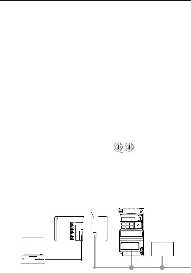
Set the 10s digit on the left rotary switch and set the 1s digit on the right rotary switch. The setting of the switches is read when the Unit power supply turns ON.
There are two ways of configuring the CompoNetNode number.
1.Set the node address by the rotary switches to a valid value in the range 0 to 63.
2.Set the node address by Inverter parameter P190. Set the rotary switches to an invalid value (between 64 to 99) to set the node address as the value of the P190 parameter
See Section 3-2 Configuring the Option Board on page 15 for more details.
2-2 Basic System Description
CompoNet CRM21 Master
PLC |
MX2-A@ Inverter |
+ |
Option Board |
Slave
PC |
CompoNet network |
|
The Option Board connects to the Master via a CompoNet network cable. Inverter I/O data is generally shared with the Master's I/O memory through the CompoNet network. Every CompoNet communication cycle, Inverter I/O data
9
Step-by-Step Basic Installation |
Section 2-3 |
is collected by the Option Board and exchanged with the Master. The PC (personal computer) allows you to configure, monitor, program, diagnose and operate the system.
2-3 Step-by-Step Basic Installation
2-3-1 Option Board Mounting
!HIGH VOLTAGE Always switch OFF the mains power supply to the Inverter before removing any covers. Wait for the time specified on the Inverter front cover for the capacitors to discharge. Not doing so may result in electrical shock.
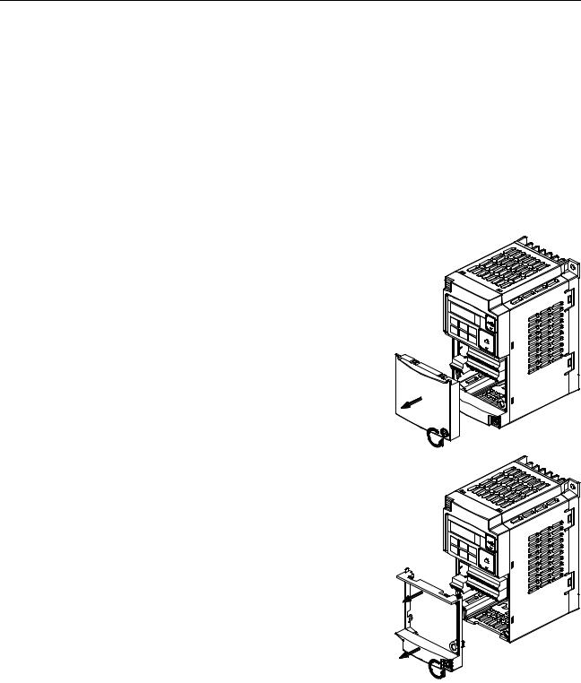
Step 1 Loosen the screw of the option board cover, remove the cover and put the cover aside.
Step 2 For Inverters up to 4.0 kW only: loosen the screws of the terminal block cover and remove the cover to enable access to the chassis ground terminal screws.
10
Step-by-Step Basic Installation |
Section 2-3 |
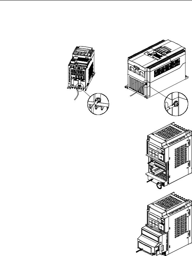
Step 3 Secure the Option Board grounding cable to the MX2-A@ Inverter with a |
|
mounting screw. |
|
1-phase 200 V 0.1 - 2.2 kW |
3-phase 200 V 5.5 - 15 kW |
3-phase 200 V 0.1 - 3.7 kW |
3-phase 400 V 5.5 - 15 kW |
3-phase 400 V 0.4 - 4.0 kW |
|
Step 4 If removed in Step 2, mount the terminal cover again and tighten the screw(s).
Step 5 Push the Option Board into the previous location of the option board cover until it clicks into place
11
Step-by-Step Basic Installation |
Section 2-3 |
Step 6 Press down on the indicated corner of the Option Board housing to ensure proper connection of the Option Board connector
Step 7 Check that there is no gap between the top edges of the Option Board and the Inverter casing.
Step 8 Secure the Option
Board in place with the mounting screw (do not over-tighten).
Step 9 Select the right warning language from the warning label sheet and replace the English warning if appropriate.
Note 1 Refer to section 2-1-3 in the MX2 User's Manual (Cat. No. I570) for operations related to assembly and disassembly of the MX2-A@ Inverter:
Note 2 Some Inverter models do not include a screw for the grounding cable. Please supply the recommended screw, lock-washer and washer to attach the grounding cable.
Table 4 Ground cable screw selection
Inverter models |
Grounding Cable Attachment Screw |
|
|
3-phase 200 V 5.5 – 7.5 kW |
M4 x 6 |
|
|
3-phase 400 V 5.5 – 7.5 kW |
|
|
|
12

Step-by-Step Basic Installation |
Section 2-3 |
Table 4 Ground cable screw selection (continued)
Inverter models |
Grounding Cable Attachment Screw |
|
|
3-phase 200 V 11 – 15 kW |
M5 x 6 |
|
|
3-phase 400 V 11 – 15 kW |
|
|
|
Note 3 Illustrations are only provided for one Inverter size. The instructions however are generic, and may be followed for all Inverter sizes. Make use of the MX2-A@ Inverter manual.
!HIGH VOLTAGE Never operate the Inverter with the terminal block cover or backing plate removed.
!WARNING Always connect the grounding cable to one of the ground terminals of the MX2-A@ Inverter. Failure to abide could lead to serious or possibly fatal injury.
!WARNING Provide emergency stop circuits, interlock circuits, limit circuits and similar safety measures in external circuits (NOT in the Option Board). This ensures safety in the system if an abnormality occurs due to malfunction of the Option Board or another external factor affecting the Option Board operation. Not doing so may result in serious accidents.
!Caution Never touch the heat sink during or just after operation; it can be very hot.
!Caution Be sure that the Option Board is mounted correctly. Improper mounting may result in malfunction.
!Caution Be sure that all cable connector screws are tightened to the torque specified in the relevant manuals. Incorrect tightening torque may result in malfunction.
2-3-2 Installation Environment Clearance
Please adhere to the requirements of section 2-3-2 in the MX2 User's manual (Cat. No. I570) on "Installation Environment clearance". In addition to this, provide sufficient clearance to allow connection and removal of the CompoNet connector. No unnecessary strain should be placed on the CompoNet cable or connector that could be transferred to the Option Board.
2-3-3 CompoNet network connector
You can use different types of communications cable in as CompoNet network. You can use the connector to connect either a flat cable or round cable. Refer to the CS/CJ-Series CompoNet Master Unit Operation Manual (Cat. No. W456) for the connection procedure.
Table 5 CompoNet connector signals
|
Colour |
Signal |
Description |
|
|
|
|
|
Red |
BS+ |
Communications power supply (24VDC) |
|
|
|
|
|
White |
BDH |
Communications data lines (high) |
|
|
|
|
|
Blue |
BDL |
Communications data lines (low) |
|
|
|
|
|
Black |
BS- |
Communications power supply (0VDC) |
|
|
|
|
Note The BS+ (communications power supply +) and BS- (communications power supply -) are not connected internally in the Option Board. Connecting them on the connector is not strictly required.
13
Step-by-Step Basic Installation |
Section 2-3 |
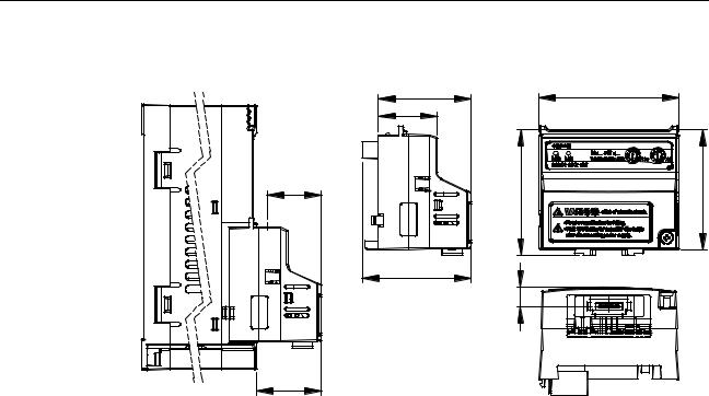
2-3-4 Option Board Dimensions
d1 |
d2 |
d3 |
d4 |
d |
|
w |
h |
h1 |
c |
Table 6 Option Board Dimensions |
|
|
|
|
|||
|
|
|
|
|
|
|
|
Item |
Dimension |
|
Item |
Dimension |
|
Item |
Dimension |
|
|
|
|
|
|
|
|
h |
60.7 mm |
|
c |
18.7 mm |
|
d2 |
31.3 mm |
|
|
|
|
|
|
|
|
h1 |
57.9 mm |
|
d |
52.6 mm |
|
d3 |
44.8 mm |
w |
67.6 mm |
|
d11 |
26.4 mm |
|
d4 |
28.4 mm |
1.Dimension d1 gives the increase in MX2-A@ Inverter dimension D when the Option Board is fitted. Please refer to section 2-3 of the MX2 User's manual (Cat. No. I570).
14
Loading...