


Cat. No. W334-E1-04
SYSMAC
C200HW-NC113/NC213/NC413
Position Control Units
C200HW-NC113/NC213/NC413
Position Control Units
Operation Manual
Revised July 2003
iv
Notice:
OMRON products are manufactured for use according to proper procedures by a qualified operator and only for the purposes described in this manual.
The following conventions are used to indicate and classify precautions in this manual. Always heed the information provided with them. Failure to heed precautions can result in injury to people or damage to property.
! DANGER Indicates an imminently hazardous situation which, if not avoided, will result in death or serious injury.
! WARNING Indicates a potentially hazardous situation which, if not avoided, could result in death or serious injury.
! Caution Indicates a potentially hazardous situation which, if not avoided, may result in minor or moderate injury, or property damage.
OMRON Product References
All OMRON products are capitalized in this manual. The word “Unit” is also capitalized when it refers to an OMRON product, regardless of whether or not it appears in the proper name of the product.
The abbreviation “Ch,” which appears in some displays and on some OMRON products, often means “word” and is abbreviated “Wd” in documentation in this sense.
The abbreviation “PC” means Programmable Controller and is not used as an abbreviation for anything else.
Visual Aids
The following headings appear in the left column of the manual to help you locate different types of information.
Note Indicates information of particular interest for efficient and convenient operation of the product.
1, 2, 3... 1. Indicates lists of one sort or another, such as procedures, checklists, etc.
OMRON, 1997
All rights reserved. No part of this publication may be reproduced, stored in a retrieval system, or transmitted, in any form, or by any means, mechanical, electronic, photocopying, recording, or otherwise, without the prior written permission of OMRON.
No patent liability is assumed with respect to the use of the information contained herein. Moreover, because OMRON is constantly striving to improve its high-quality products, the information contained in this manual is subject to change without notice. Every precaution has been taken in the preparation of this manual. Nevertheless, OMRON assumes no responsibility for errors or omissions. Neither is any liability assumed for damages resulting from the use of the information contained in this publication.
v
vi
TABLE OF CONTENTS
PRECAUTIONS . . . . . . . . . . . . . . . . . . . . . . . . . . . . . . . . . |
xiii |
|
1 Intended Audience . . . . . . . . . . . . . . . . . . . . . . . . . . . . . . . . . . . . . . . . . . . . . . . . . . . . . . . . . . . |
xiv |
|
2 General Precautions . . . . . . . . . . . . . . . . . . . . . . . . . . . . . . . . . . . . . . . . . . . . . . . . . . . . . . . . . . |
xiv |
|
3 Safety Precautions . . . . . . . . . . . . . . . . . . . . . . . . . . . . . . . . . . . . . . . . . . . . . . . . . . . . . . . . . . . |
xiv |
|
4 Operating Environment Precautions . . . . . . . . . . . . . . . . . . . . . . . . . . . . . . . . . . . . . . . . . . . . . |
xv |
|
5 Application Precautions . . . . . . . . . . . . . . . . . . . . . . . . . . . . . . . . . . . . . . . . . . . . . . . . . . . . . . |
xv |
|
SECTION 1 |
|
|
Introduction . . . . . . . . . . . . . . . . . . . . . . . . . . . . . . . . . . . . |
1 |
|
1-1 |
Features . . . . . . . . . . . . . . . . . . . . . . . . . . . . . . . . . . . . . . . . . . . . . . . . . . . . . . . . . . . . . . . |
2 |
1-2 |
System Configuration . . . . . . . . . . . . . . . . . . . . . . . . . . . . . . . . . . . . . . . . . . . . . . . . . . . . . |
4 |
1-3 |
Basic Operations . . . . . . . . . . . . . . . . . . . . . . . . . . . . . . . . . . . . . . . . . . . . . . . . . . . . . . . . |
7 |
1-4 |
Control System Principles . . . . . . . . . . . . . . . . . . . . . . . . . . . . . . . . . . . . . . . . . . . . . . . . . |
11 |
1-5 |
Exchanging Data . . . . . . . . . . . . . . . . . . . . . . . . . . . . . . . . . . . . . . . . . . . . . . . . . . . . . . . . |
13 |
1-6 |
Before Operation . . . . . . . . . . . . . . . . . . . . . . . . . . . . . . . . . . . . . . . . . . . . . . . . . . . . . . . . |
15 |
SECTION 2 |
|
|
Specifications and Wiring . . . . . . . . . . . . . . . . . . . . . . . . . |
17 |
|
2-1 |
Specifications . . . . . . . . . . . . . . . . . . . . . . . . . . . . . . . . . . . . . . . . . . . . . . . . . . . . . . . . . . . |
18 |
2-2 |
Components . . . . . . . . . . . . . . . . . . . . . . . . . . . . . . . . . . . . . . . . . . . . . . . . . . . . . . . . . . . . |
21 |
2-3 |
External I/O Circuitry . . . . . . . . . . . . . . . . . . . . . . . . . . . . . . . . . . . . . . . . . . . . . . . . . . . . |
24 |
2-4 |
Connecting External I/O . . . . . . . . . . . . . . . . . . . . . . . . . . . . . . . . . . . . . . . . . . . . . . . . . . |
30 |
2-5 Connections in Each Operating Mode . . . . . . . . . . . . . . . . . . . . . . . . . . . . . . . . . . . . . . . . |
37 |
|
2-6 Connection of Unused Axes . . . . . . . . . . . . . . . . . . . . . . . . . . . . . . . . . . . . . . . . . . . . . . . . |
45 |
|
2-7 |
Servo Relay Unit . . . . . . . . . . . . . . . . . . . . . . . . . . . . . . . . . . . . . . . . . . . . . . . . . . . . . . . . |
45 |
SECTION 3 |
|
|
Getting Started . . . . . . . . . . . . . . . . . . . . . . . . . . . . . . . . . . |
47 |
|
3-1 |
Basic Operations . . . . . . . . . . . . . . . . . . . . . . . . . . . . . . . . . . . . . . . . . . . . . . . . . . . . . . . . |
48 |
3-2 System Configuration and Wiring . . . . . . . . . . . . . . . . . . . . . . . . . . . . . . . . . . . . . . . . . . . |
49 |
|
3-3 Setting Data and Starting . . . . . . . . . . . . . . . . . . . . . . . . . . . . . . . . . . . . . . . . . . . . . . . . . . |
51 |
|
SECTION 4 |
|
|
Data Areas . . . . . . . . . . . . . . . . . . . . . . . . . . . . . . . . . . . . . |
53 |
|
4-1 |
Overall Structure . . . . . . . . . . . . . . . . . . . . . . . . . . . . . . . . . . . . . . . . . . . . . . . . . . . . . . . . |
54 |
4-2 |
Common Parameters . . . . . . . . . . . . . . . . . . . . . . . . . . . . . . . . . . . . . . . . . . . . . . . . . . . . . |
74 |
4-3 |
Axis Parameters . . . . . . . . . . . . . . . . . . . . . . . . . . . . . . . . . . . . . . . . . . . . . . . . . . . . . . . . . |
76 |
4-4 |
Operating Memory Area . . . . . . . . . . . . . . . . . . . . . . . . . . . . . . . . . . . . . . . . . . . . . . . . . . |
83 |
4-5 |
Operating Data Area . . . . . . . . . . . . . . . . . . . . . . . . . . . . . . . . . . . . . . . . . . . . . . . . . . . . . |
89 |
4-6 |
Positioning Sequence Details . . . . . . . . . . . . . . . . . . . . . . . . . . . . . . . . . . . . . . . . . . . . . . . |
89 |
4-7 Setting Data With the SYSMAC-NCT Support Tool . . . . . . . . . . . . . . . . . . . . . . . . . . . . |
93 |
|
4-8 Setting Data for Unused Axes . . . . . . . . . . . . . . . . . . . . . . . . . . . . . . . . . . . . . . . . . . . . . . |
93 |
|
SECTION 5 |
|
|
Transferring and Saving Data . . . . . . . . . . . . . . . . . . . . . |
95 |
|
5-1 |
Transferring and Saving Data . . . . . . . . . . . . . . . . . . . . . . . . . . . . . . . . . . . . . . . . . . . . . . |
96 |
5-2 Writing Data with the WRITE DATA Bit . . . . . . . . . . . . . . . . . . . . . . . . . . . . . . . . . . . . . |
99 |
|
5-3 Reading Data with the READ DATA Bit . . . . . . . . . . . . . . . . . . . . . . . . . . . . . . . . . . . . . . |
103 |
|
5-4 Writing Data with IOWR . . . . . . . . . . . . . . . . . . . . . . . . . . . . . . . . . . . . . . . . . . . . . . . . . . |
107 |
|
5-5 Reading Data with IORD . . . . . . . . . . . . . . . . . . . . . . . . . . . . . . . . . . . . . . . . . . . . . . . . . . |
110 |
|
5-6 Creating and Transferring Data with the Support Tool . . . . . . . . . . . . . . . . . . . . . . . . . . . |
113 |
|
5-7 |
Saving Data . . . . . . . . . . . . . . . . . . . . . . . . . . . . . . . . . . . . . . . . . . . . . . . . . . . . . . . . . . . . |
114 |
vii
TABLE OF CONTENTS
SECTION 6 |
|
|
Defining the Origin . . . . . . . . . . . . . . . . . . . . . . . . . . . . . . |
117 |
|
6-1 |
Setting the Data for an Origin Search . . . . . . . . . . . . . . . . . . . . . . . . . . . . . . . . . . . . . . . . |
118 |
6-2 |
Executing Origin Search . . . . . . . . . . . . . . . . . . . . . . . . . . . . . . . . . . . . . . . . . . . . . . . . . . |
119 |
6-3 |
Origin Search Timing Charts . . . . . . . . . . . . . . . . . . . . . . . . . . . . . . . . . . . . . . . . . . . . . . . |
130 |
6-4 |
Origin Return . . . . . . . . . . . . . . . . . . . . . . . . . . . . . . . . . . . . . . . . . . . . . . . . . . . . . . . . . . . |
134 |
SECTION 7 |
|
|
Direct Operation . . . . . . . . . . . . . . . . . . . . . . . . . . . . . . . . |
137 |
|
7-1 |
Outline . . . . . . . . . . . . . . . . . . . . . . . . . . . . . . . . . . . . . . . . . . . . . . . . . . . . . . . . . . . . . . . . |
138 |
7-2 |
Setting Data for Use With Direct Operation . . . . . . . . . . . . . . . . . . . . . . . . . . . . . . . . . . . |
140 |
7-3 |
Operations With Direct Operation . . . . . . . . . . . . . . . . . . . . . . . . . . . . . . . . . . . . . . . . . . . |
141 |
7-4 |
Procedures for Setting Data for Direct Operation . . . . . . . . . . . . . . . . . . . . . . . . . . . . . . . |
143 |
7-5 |
Direct Operation Timing Charts . . . . . . . . . . . . . . . . . . . . . . . . . . . . . . . . . . . . . . . . . . . . |
144 |
7-6 |
Sample Program . . . . . . . . . . . . . . . . . . . . . . . . . . . . . . . . . . . . . . . . . . . . . . . . . . . . . . . . . |
146 |
SECTION 8 |
|
|
Memory Operation . . . . . . . . . . . . . . . . . . . . . . . . . . . . . . |
149 |
|
8-1 |
Outline . . . . . . . . . . . . . . . . . . . . . . . . . . . . . . . . . . . . . . . . . . . . . . . . . . . . . . . . . . . . . . . . |
150 |
8-2 |
Setting Data for Use in Memory Operation . . . . . . . . . . . . . . . . . . . . . . . . . . . . . . . . . . . . |
154 |
8-3 |
Operations With Memory Operation . . . . . . . . . . . . . . . . . . . . . . . . . . . . . . . . . . . . . . . . . |
155 |
8-4 |
Procedures for Setting Data for Memory Operation . . . . . . . . . . . . . . . . . . . . . . . . . . . . . |
162 |
8-5 |
Timing Chart for Memory Operation . . . . . . . . . . . . . . . . . . . . . . . . . . . . . . . . . . . . . . . . . |
162 |
8-6 |
Sample Program . . . . . . . . . . . . . . . . . . . . . . . . . . . . . . . . . . . . . . . . . . . . . . . . . . . . . . . . . |
165 |
SECTION 9 |
|
|
Other Operations . . . . . . . . . . . . . . . . . . . . . . . . . . . . . . . . |
169 |
|
9-1 |
Jogging . . . . . . . . . . . . . . . . . . . . . . . . . . . . . . . . . . . . . . . . . . . . . . . . . . . . . . . . . . . . . . . . |
170 |
9-2 |
Teaching . . . . . . . . . . . . . . . . . . . . . . . . . . . . . . . . . . . . . . . . . . . . . . . . . . . . . . . . . . . . . . . |
171 |
9-3 |
Interrupt Feeding . . . . . . . . . . . . . . . . . . . . . . . . . . . . . . . . . . . . . . . . . . . . . . . . . . . . . . . . |
173 |
9-4 |
Forced Interrupt . . . . . . . . . . . . . . . . . . . . . . . . . . . . . . . . . . . . . . . . . . . . . . . . . . . . . . . . . |
175 |
9-5 |
Deceleration Stop . . . . . . . . . . . . . . . . . . . . . . . . . . . . . . . . . . . . . . . . . . . . . . . . . . . . . . . . |
177 |
9-6 |
Changing the Present Position . . . . . . . . . . . . . . . . . . . . . . . . . . . . . . . . . . . . . . . . . . . . . . |
180 |
9-7 |
Override . . . . . . . . . . . . . . . . . . . . . . . . . . . . . . . . . . . . . . . . . . . . . . . . . . . . . . . . . . . . . . . |
181 |
9-8 |
Releasing Pulse Output Prohibition . . . . . . . . . . . . . . . . . . . . . . . . . . . . . . . . . . . . . . . . . . |
182 |
9-9 |
Error Counter Reset Output and Origin Adjustment Command Output . . . . . . . . . . . . . . |
184 |
9-10 |
Backlash Compensation . . . . . . . . . . . . . . . . . . . . . . . . . . . . . . . . . . . . . . . . . . . . . . . . . . . |
187 |
SECTION 10 |
|
|
Program Examples . . . . . . . . . . . . . . . . . . . . . . . . . . . . . . |
189 |
|
10-1 |
Operating Procedures for Program Examples . . . . . . . . . . . . . . . . . . . . . . . . . . . . . . . . . . |
190 |
10-2 |
Memory Operation . . . . . . . . . . . . . . . . . . . . . . . . . . . . . . . . . . . . . . . . . . . . . . . . . . . . . . . |
192 |
10-3 |
Direct Operation . . . . . . . . . . . . . . . . . . . . . . . . . . . . . . . . . . . . . . . . . . . . . . . . . . . . . . . . . |
206 |
10-4 |
Linear Interpolation . . . . . . . . . . . . . . . . . . . . . . . . . . . . . . . . . . . . . . . . . . . . . . . . . . . . . . |
211 |
10-5 |
Origin Search . . . . . . . . . . . . . . . . . . . . . . . . . . . . . . . . . . . . . . . . . . . . . . . . . . . . . . . . . . . |
216 |
10-6 |
Override . . . . . . . . . . . . . . . . . . . . . . . . . . . . . . . . . . . . . . . . . . . . . . . . . . . . . . . . . . . . . . . |
218 |
10-7 Transferring and Saving Data . . . . . . . . . . . . . . . . . . . . . . . . . . . . . . . . . . . . . . . . . . . . . . |
221 |
|
SECTION 11 |
|
|
Troubleshooting . . . . . . . . . . . . . . . . . . . . . . . . . . . . . . . . . |
227 |
|
11-1 |
Introduction . . . . . . . . . . . . . . . . . . . . . . . . . . . . . . . . . . . . . . . . . . . . . . . . . . . . . . . . . . . . |
228 |
11-2 |
LED Error Indicators . . . . . . . . . . . . . . . . . . . . . . . . . . . . . . . . . . . . . . . . . . . . . . . . . . . . . |
230 |
11-3 |
Reading Error Codes . . . . . . . . . . . . . . . . . . . . . . . . . . . . . . . . . . . . . . . . . . . . . . . . . . . . . |
231 |
11-4 |
Error Code Lists . . . . . . . . . . . . . . . . . . . . . . . . . . . . . . . . . . . . . . . . . . . . . . . . . . . . . . . . . |
232 |
11-5 |
CPU Error Indicators . . . . . . . . . . . . . . . . . . . . . . . . . . . . . . . . . . . . . . . . . . . . . . . . . . . . . |
243 |
viii
TABLE OF CONTENTS |
|
Appendices |
|
A Data Calculation Standards . . . . . . . . . . . . . . . . . . . . . . . . . . . . . . . . . . . . . . . . . . . . . . . . . . . |
245 |
B Estimating Times and Pulses for Acceleration/Deceleration . . . . . . . . . . . . . . . . . . . . . . . . . |
251 |
C Error Code List . . . . . . . . . . . . . . . . . . . . . . . . . . . . . . . . . . . . . . . . . . . . . . . . . . . . . . . . . . . . |
253 |
D Effect of Cable Length on Pulse Output . . . . . . . . . . . . . . . . . . . . . . . . . . . . . . . . . . . . . . . . . |
257 |
E Parameter Coding Sheets . . . . . . . . . . . . . . . . . . . . . . . . . . . . . . . . . . . . . . . . . . . . . . . . . . . . . |
259 |
F Using with CS1-series PCs . . . . . . . . . . . . . . . . . . . . . . . . . . . . . . . . . . . . . . . . . . . . . . . . . . . |
263 |
Index . . . . . . . . . . . . . . . . . . . . . . . . . . . . . . . . . . . . . . . . . . |
271 |
Revision History . . . . . . . . . . . . . . . . . . . . . . . . . . . . . . . . . |
277 |
ix
About this Manual:
This manual describes the operation of the C200HW-NC113/NC213/NC413 Position Control Units and includes the sections described below.
Please read this manual carefully and be sure you understand the information provided before attempting to install and operate the C200HW-NC113/NC213/NC413 Position Control Units.
Section 1 introduces the features of the Position Control Unit and explains the system configuration in which it is used.
Section 2 provides the Position Control Unit’s specifications and explains the wiring.
Section 3 explains how to use the RELATIVE MOVEMENT command employing the direct operation method, and provides examples of how to use a stepping motor.
Section 4 provides information on the data areas used by the Position Control Unit.
Section 5 explains how to transfer and save parameters and data.
Section 6 explains the origin search and origin return operations.
Section 7 provides an outline of direct operation, details about data areas and how to set data, and sample programs.
Section 8 provides an outline of memory operation, details about data areas and how to set data, and sample programs.
Section 9 describes the following operations: jogging, teaching, interrupt feeding, forced interrupt, deceleration stop, changing the present position, override, releasing pulse output prohibition, deviation counter reset output/origin-adjustment command output, and backlash compensation.
Section 10 provides examples of programs for using the Position Control Unit.
Section 11 describes how to diagnose and correct errors that can occur during operation.
The Appendices provide data calculation standards, information on estimating times and pulses for acceleration/deceleration, error code list, information on the effect of cable length on pulse output, and parameter coding sheets.
! WARNING Failure to read and understand the information provided in this manual may result in personal injury or death, damage to the product, or product failure. Please read each section in its entirety and be sure you understand the information provided in the section and related sections before attempting any of the procedures or operations given.
xi
PRECAUTIONS
This section provides general precautions for using the Programmable Controller (PC), Position Control Unit (PCU), and related devices.
The information contained in this section is important for the safe and reliable application of the Programmable Controller and the Position Control Unit. You must read this section and understand the information contained before attempting to set up or operate a PC system.
1 Intended Audience . . . . . . . . . . . . . . . . . . . . . . . . . . . . . . . . . . . . . . . . . . . . . . . . . . . . . . . . . . . . |
xiv |
|
2 |
General Precautions . . . . . . . . . . . . . . . . . . . . . . . . . . . . . . . . . . . . . . . . . . . . . . . . . . . . . . . . . . . |
xiv |
3 |
Safety Precautions . . . . . . . . . . . . . . . . . . . . . . . . . . . . . . . . . . . . . . . . . . . . . . . . . . . . . . . . . . . . |
xiv |
4 Operating Environment Precautions . . . . . . . . . . . . . . . . . . . . . . . . . . . . . . . . . . . . . . . . . . . . . . |
xv |
|
5 |
Application Precautions . . . . . . . . . . . . . . . . . . . . . . . . . . . . . . . . . . . . . . . . . . . . . . . . . . . . . . . . |
xv |
xiii
Safety Precautions |
3 |
1 Intended Audience
This manual is intended for the following personnel, who must also have knowledge of electrical systems (an electrical engineer or the equivalent).
•Personnel in charge of installing FA systems.
•Personnel in charge of designing FA systems.
•Personnel in charge of managing FA systems and facilities.
2 General Precautions
The user must operate the product according to the performance specifications described in the operation manuals.
Before using the product under conditions which are not described in the manual or applying the product to nuclear control systems, railroad systems, aviation systems, vehicles, combustion systems, medical equipment, amusement machines, safety equipment, and other systems, machines, and equipment that may have a serious influence on lives and property if used improperly, consult your OMRON representative.
Make sure that the ratings and performance characteristics of the product are sufficient for the systems, machines, and equipment, and be sure to provide the systems, machines, and equipment with double safety mechanisms.
This manual provides information for programming and operating Position Control Unit. Be sure to read this manual before attempting to use the PCU and keep this manual close at hand for reference during operation.
3Safety Precautions
!WARNING Never attempt to disassemble any Units while power is being supplied. Doing so
may result in serious electrical shock or electrocution.
! WARNING Never touch any of the terminals while power is being supplied. Doing so may result in serious electrical shock or electrocution.
! WARNING Provide safety measures in external circuits (i.e., not in the Programmable Controller), including the following items, to ensure safety in the system if an abnormality occurs due to malfunction of the PC or another external factor affecting the PC operation. Not doing so may result in serious accidents.
•Emergency stop circuits, interlock circuits, limit circuits, and similar safety measures must be provided in external control circuits.
•The PC will turn OFF all outputs when its self-diagnosis function detects any error or when a severe failure alarm (FALS) instruction is executed. As a countermeasure for such errors, external safety measures must be provided to ensure safety in the system.
•The PC outputs may remain ON or OFF due to deposits on or burning of the output relays, or destruction of the output transistors. As a countermeasure for such problems, external safety measures must be provided to ensure safety in the system.
•When the 24-V DC output (service power supply to the PC) is overloaded or short-circuited, the voltage may drop and result in the outputs being turned OFF. As a countermeasure for such problems, external safety measures must be provided to ensure safety in the system.
!Caution Tighten the screws on the terminal block on the AC Power Supply Unit to the
torque specified in the C200H, C200HS, or C200HX/HG/HE-(Z)E installation guide. Loose screws may result in short-circuits, malfunction, or burning.
xiv

Application Precautions |
5 |
! Caution Confirm safety at the destination node before transferring a program to another node or editing the I/O area. Doing either of these without confirming safety may result in injury.
4 Operating Environment Precautions
Do not operate the control system in the following places.
•Locations subject to direct sunlight.
•Locations subject to temperatures or humidity outside the range specified in the specifications.
•Locations subject to condensation as the result of severe changes in temperature.
•Locations subject to corrosive or flammable gases.
•Locations subject to dust (especially iron dust) or salts.
•Locations subject to shock or vibration.
•Locations subject to exposure to water, oil, or chemicals.
•Take appropriate and sufficient countermeasures when installing systems in the following locations.
•Locations subject to static electricity or other forms of noise.
•Locations subject to strong electric fields or magnetic fields.
•Locations subject to possible exposure to radioactivity.
•Locations close to power supplies.
5 Application Precautions
Observe the following precautions when using the Position Control Unit (PCU) and Programmable Controller (PC).
! WARNING Failure to abide by the following precautions could lead to serious or possibly fatal injury. Always heed these precautions.
•Always ground the system to 100 Ω or less when installing the system to protect against electrical shock.
•Always turn off the power supply to the PC before attempting any of the following:
•Mounting or dismounting the Power Supply Unit, I/O Units, CPU Unit, other Units, or Memory Casettes.
•Assembling the devices.
•Setting DIP switches or rotary switches.
•Wiring or connecting cables.
•Connecting or disconnecting the connectors.
!Caution Failure to abide by the following precautions could lead to faulty operation of the
PC or the system or could damage the PC or PC Units. Always heed these precautions.
•Fail-safe measures must be taken by the customer to ensure safety in the event of incorrect, missing, or abnormal signals caused by broken signal lines, momentary power interruptions, or other causes.
•Interlock circuits, limit circuits, and similar safety measures must be provided by the customer as external circuits.
•Install external breakers and take other safety measures against short-circuit- ing in external wiring.
xv

Application Precautions |
5 |
•Tighten the PC mounting screws, terminal block screws, and cable screws to the torque specified in this manuals.
•Always use the power supply voltage specified in this manual.
•Take appropriate measures to ensure that the specified power with the rated voltage and frequency is supplied. Be particularly careful in places where the power supply is unstable.
•Use crimp terminals for wiring. Do not connect bare stranded wires directly to terminals.
•Leave the dustproof labels affixed to the top of the Unit when wiring. After wiring, remove the labels for proper heat radiation.
•Do not apply voltages to the Input Units in excess of the rated input voltage.
•Do not apply voltages or connect loads to the Output Units in excess of the maximum switching capacity.
•Check the user program for proper execution before actually running it in the Unit.
•Be sure that the terminal blocks, memory units, extension cables, and other items with locking devices are properly locked.
•Double-check all the wiring before turning on the power supply.
•Disconnect the functional ground terminal when performing withstand voltage tests.
•Confirm that no adverse effect will occur in the system before performing the following operations:
•Changing the operating mode of the PC.
•Force-setting/resetting the relay contacts.
•Changing the present values or set values.
•Changing positioning data or parameters.
•Resume operation only after transferring to the new CPU Unit the contents of the DM and HR Areas required for operation.
•Do not attempt to disassemble, repair, or modify any Units.
•Do not pull on or bend the cables beyond their natural limit. Doing so may break the cables.
•Do not place heavy objects on top of the cables. Doing so may break the cables.
•Resume operation only after saving in the Position Control Unit the parameters and position data required for resuming operation.
•Be sure that the set parameters and data operate properly.
•Be sure to check the pin numbers before wiring the connectors.
xvi
SECTION 1
Introduction
This section introduces the features of the Position Control Unit and explains the system configuration in which it is used.
1-1 |
Features |
. . . . . . . . . . . . . . . . . . . . . . . . . . . . . . . . . . . . . . . . . . . . . . . . . . . . . . . . . . . . . . . . |
2 |
1-2 |
System Configuration . . . . . . . . . . . . . . . . . . . . . . . . . . . . . . . . . . . . . . . . . . . . . . . . . . . . . . |
4 |
|
1-3 |
Basic Operations . . . . . . . . . . . . . . . . . . . . . . . . . . . . . . . . . . . . . . . . . . . . . . . . . . . . . . . . . |
7 |
|
|
1-3-1 |
Position Control . . . . . . . . . . . . . . . . . . . . . . . . . . . . . . . . . . . . . . . . . . . . . . . . . . . |
7 |
|
1-3-2 |
Speed Control . . . . . . . . . . . . . . . . . . . . . . . . . . . . . . . . . . . . . . . . . . . . . . . . . . . . |
8 |
|
1-3-3 |
Other Operations . . . . . . . . . . . . . . . . . . . . . . . . . . . . . . . . . . . . . . . . . . . . . . . . . . |
8 |
1-4 |
Control System Principles . . . . . . . . . . . . . . . . . . . . . . . . . . . . . . . . . . . . . . . . . . . . . . . . . . |
11 |
|
|
1-4-1 |
Data Flow . . . . . . . . . . . . . . . . . . . . . . . . . . . . . . . . . . . . . . . . . . . . . . . . . . . . . . . . |
11 |
|
1-4-2 |
Control System Principles . . . . . . . . . . . . . . . . . . . . . . . . . . . . . . . . . . . . . . . . . . . |
12 |
|
1-4-3 Basic Positioning System Design . . . . . . . . . . . . . . . . . . . . . . . . . . . . . . . . . . . . . |
12 |
|
1-5 |
Exchanging Data . . . . . . . . . . . . . . . . . . . . . . . . . . . . . . . . . . . . . . . . . . . . . . . . . . . . . . . . . |
13 |
|
|
1-5-1 Explanation . . . . . . . . . . . . . . . . . . . . . . . . . . . . . . . . . . . . . . . . . . . . . . . . . . . . . . |
14 |
|
1-6 |
Before Operation . . . . . . . . . . . . . . . . . . . . . . . . . . . . . . . . . . . . . . . . . . . . . . . . . . . . . . . . . |
15 |
|
1
Features |
Section 1-1 |
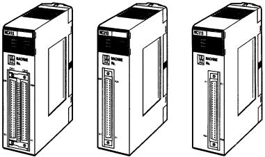
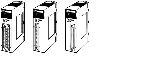
1-1 Features
Position Control Unit
C200HW-NC413 |
C200HW-NC213 |
C200HW-NC113 |
(4-axis control) |
(2-axis control) |
(1-axis control) |
Functions
Motor Driver Selectable by Axis Unit
Number of Control Axes
and Control Capacity
Memory Operation and
Direct Operation
Interrupt Feeding
High-speed Response
Compact Size
Special Support Tool
(SYSMAC-NCT)
These Position Control Units are C200HX/HG/HE-series and C200H/HS-series Special I/O Units. The Units receive instructions from the Programmable Controller’s IR area and output pulse trains to various motor drivers for positioning.
The operating mode can be set by axis unit, so it is possible to select the motor driver by axis unit. The Position Control Unit outputs pulse trains, so it can easily be connected to the following motor drivers.
•Stepping motor driver
•Servomotor drivers with pulse input.
The Position Control Unit is available with one, two, or four control axes. With the two-axis model, the two axes can either be used together for linear interpolation or they can be operated independently. With the four-axis model, up to four axes can be used together for linear interpolation or the axes can all be operated independently.
There are two different control methods. The first is memory operation, in which the data required for positioning is transferred to the Position Control Unit and then specified for position control, and the second is direct operation, in which the target position and target speed are set each time from the Programmable Controller.
When an interrupt is input during pulse output, positioning is continued for only the specified number of pulses and then stopped.
The Position Control Unit responds to instructions from the Programmable Controller within 10 ms. (This applies to the C200HW-NC113.)
The single-axis, two-axis, and four-axis models are all one size, so space efficiency can be maximized by using multi-axis control with the two-axis and fouraxis models.
A special support tool, SYSMAC-NCT, that runs on Windows 95 can be used with C200HX/HG/HE-series Programmable Controllers. The SYSMAC-NCT Support Tool can be used for writing data created or edited at a personal computer to the PCU, for reading data from the PCU, and for saving or printing out data. It also enables the monitoring of status such as I/O and positioning sequence numbers during execution. For details on operating this Support Tool, refer to the SYSMAC-NCT Support Tool Operation Manual.
2

Features |
Section 1-1 |
Data Capacity and
Backup
Note
High-speed Data Transfer
The SYSMAC-NCT Support Tool can only be used to access PCUs mounted on a CPU Rack or an Expansion I/O Rack. It cannot access PCUs mounted on Slave Racks. The SYSMAC-NCT Support Tool cannot be used with C200H/C200HS CPU Units.
The amounts of data that can be set for memory operation are shown in the following table:
Type of data |
Number of data items per axis |
|
|
Positioning sequences, speeds, positions |
100 |
|
|
Acceleration times, deceleration times |
9 |
|
|
Dwell times |
19 |
|
|
Zones |
3 |
These data items are transferred to the PCU for use. Once they have been transferred to the PCU they can be saved to the PCU’s flash memory, so there is no need for battery maintenance.
There is a limit to the service life of the flash memory. A total of up to 100,000 data saving operations can be performed.
With C200HX/HG/HE-series Programmable Controllers, not only can data be transferred by means of data transfer bits and SYSMAC-NCT Support Tool, but high-speed data transfers can also be performed by means of the Intelligent I/O Write (IOWR) and Intelligent I/O Read (IORD) instructions.
3
System Configuration |
Section 1-2 |
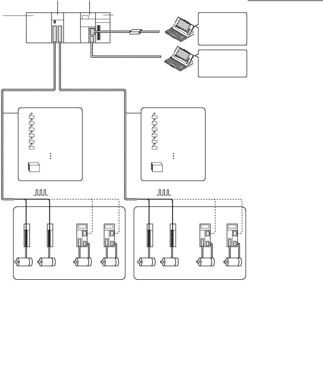
1-2 System Configuration
The Position Control Unit receives control signals (CW limit, CCW limit, origin, origin proximity, emergency stop, and external interrupt input signals) from devices and a control panel, and outputs pulse trains to stepping motor drivers and servomotor drivers.
C200HW-NC413 System Configuration Example
C200HW-NC413 |
C200HX/HG/HE |
Position Control Unit |
CPU Unit |
C200HW-BCjj |
Power Supply Unit |
|
|
Backplane |
Tool Bus |
|
SYSMAC Support Software:
Ladder program creation and transfer, monitoring, file management, etc.
Host Link
SYSMAC-NCT: Data creation and monitoring, PCU monitoring, file management, etc.
External input signals |
External input signals |
|
|
CCW limit |
CCW limit |
CW limit |
CW limit |
Origin |
Origin |
Origin Proximity |
Origin Proximity |
Emergency stop |
Emergency stop |
External interrupt |
External interrupt |
|
24-VDC power |
|
24-VDC power |
||
|
supply for I/F |
|
supply for I/F |
||
Pulse |
|
|
Pulse |
|
|
output |
|
|
output |
|
|
Stepping |
Servomotor |
Stepping |
Servomotor |
||
Motor |
|
Motor |
|
||
|
Drivers |
|
Drivers |
||
Drivers |
Drivers |
|
|||
|
|
|
|||
|
|
Or |
|
|
Or |
Stepping Motors |
Servomotors |
Stepping Motors |
Servomotors |
Number of Usable Units The Position Control Unit belongs to the SYSMAC C200H, C200HS, and C200HX/HG/HE Special I/O Unit group. The numbers of Special I/O Units (including PC Link Units) that can be mounted to a single CPU Unit are shown in the following table.
|
Item |
C200H, C200HS, C200HE, |
C200HX/HG-CPU5j/6j-(Z)E |
|
|
|
C200HX/HG-CPU3j/4j-(Z)E |
|
|
|
|
|
|
|
Number of usable |
C200HW-NC113 |
10 max. |
16 max. |
|
Units |
|
|
|
|
C200HW-NC213 |
10 max. |
16 max. |
||
|
||||
|
|
|
|
|
|
C200HW-NC413 |
5 max. |
8 max. |
•For details on the particular Units that belong to each of the Special I/O Unit groups, refer to the appropriate Programmable Controller operation manual.
4

System Configuration |
Section 1-2 |
Restrictions on Using Remote I/O Slave Racks
•There are restrictions on the maximum current provided to each Rack and the the current consumption for each Unit. For details, refer to the appropriate Programmable Controller operation manual.
•There are restrictions on the use of Remote I/O Slave Racks. These restrictions are explained in Restrictions on Using Remote I/O Slave Racks below.
As shown in the following table, the number of Special I/O Units that can be used on a single Remote I/O Slave Rack is determined by the the particular Special I/O Unit group (A, B, C, or D).
|
Group A |
Group B |
Group C |
Group D |
|
|
|
|
|
Units in |
High-speed Counter |
High-density I/O Units |
Temperature Sensor Units |
Position Control Units |
group |
Units |
Temperature Control |
Voice Unit |
(NC211) |
|
Position Control Unit |
Units |
|
(NC413) |
|
(NC111/112) |
Heat/Cool Temperature |
|
|
|
(NC113/213) |
Control Units |
|
|
|
ASCII Units |
PID Control Units |
|
|
|
Analog I/O Units |
Cam Positioner Unit |
|
|
|
ID Sensor Units |
|
|
|
|
Fuzzy Logic Units |
|
|
|
|
|
|
|
|
Number of |
4 Units |
8 Units |
6 Units |
2 Units |
Units that |
|
|
|
|
can be used |
|
|
|
|
•If Special I/O Units from different groups are to be mixed, then use a combination that satisfies the following two formulas:
3A + B + 2C + 6D x 12 A + B + C + D x 8
•There are restrictions on the number of Units that can be used with particular CPU Units. For details, refer to Number of Usable Units described previously.
System Configuration Considerations
•The I/O bits allocated to a particular Special I/O Unit are determined by the unit number that is set by the switch on the front panel of the Unit, and not by the slot in which the Unit is mounted.
•With the C200H, do not mount a Position Control Unit in the two slots adjacent to the CPU Unit. If it is mounted in those slots, it will not be possible to mount tools such as the Programming Console.
•Special I/O Units cannot be used with C200H Remote I/O Slave Racks that are connected to Remote I/O Master Racks for other SYSMAC Programmable Controller models (such as C120, C500, C1000H, and C2000H).
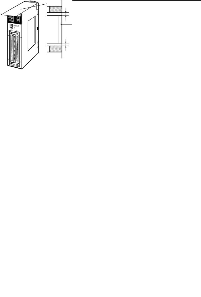
Mounting the Unit |
Follow the procedure outlined below to mount the Position Control Unit to the |
|
|
Backplane. |
|
1, 2, 3... |
1. |
Insert the hook on the upper rear of the Unit into the slot in the Backplane. |
|
|
Hook |
|
|
Backplane |
|
|
Lock lever |
|
2. |
Carefully insert the Unit into the connector on the Backplane. |
5
System Configuration |
Section 1-2 |
3.To remove the Unit. use an implement such as a screwdriver to press down on the lock lever and then carefully lift the Unit out.
Lock lever
Note When installing Units on a Rack, leave adequate space for mounting and removing the Units as shown in the following diagram.
20 mm min.
Backplane
20 mm min.
Flathead screwdriver
Precautions When Handling the Unit
•Before installing or disconnecting the Unit or connecting cable, be sure to first turn off both the Programmable Controller and the power supply.
•To minimize any influence from noise, place I/O wiring, high-voltage lines, and power lines in separate ducts.
•Wire clippings tend to get scattered around during wiring, so leave the label in place on top of the Unit to prevent any clippings from getting inside the Unit. Once the wiring has been completed, be sure to remove the label to provide ventilation.
Remove the label after completing the wiring.
6
Basic Operations Section 1-3
1-3 |
Basic Operations |
|
|
|
The C200HW-NC113 (one axis), C200HW-NC213 (two axes), and C200HW- |
|
|
NC413 (four axes) Position Control Units are designed for use with C200HX/ |
|
|
HG/HE-series and C200H/C200HS-series systems. |
1-3-1 |
Position Control |
|
|
|
Positioning can be executed with either an absolute value (i.e., to an absolute |
|
|
position from the origin) or with an incremental value (i.e., to a relative position |
|
|
from the present position). |
|
|
There are two methods for positioning: memory operation and direct operation. |
|
|
Interrupt feeding, in which operation proceeds for the specified amount after an |
|
|
interrupt input, is also possible. |
Memory Operation |
With memory operation, positioning sequences (i.e., individual positioning |
|
|
|
operations, which include data such as positions and speeds) are transferred to |
|
|
the Position Control Unit in advance, and then positioning is executed from the |
Programmable Controller by specifying those positioning sequences by number.
Executed in order
|
Positioning sequence #99 |
|
Positioning sequence #0 |
|
|
Acceleration time number |
Target speed number |
|
|
Deceleration time |
|
|
number |
|
Initial speed |
Position |
|
number |
||
|
||
|
Position |
|
Start |
Target position |
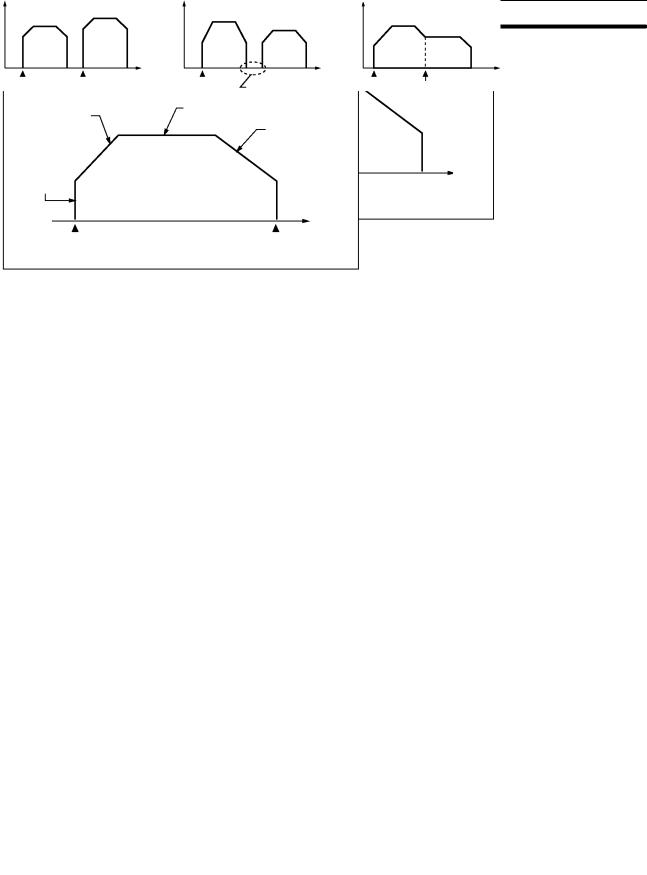
Depending on the completion code that is set, positioning sequences can be executed using terminating positioning, automatic positioning, or continuous positioning. In the following illustrations, “#0” and “#1” indicate positioning sequence numbers.
Terminating Positioning |
Automatic Positioning |
Continuous Positioning |
Pulse output |
|
Pulse output |
#0 |
#1 |
#0 |
|
|
Time |
Start |
Start |
Start |
|
Pulse output |
|
#1 |
#0 |
#1 |
|
|
|
Time |
|
Time |
Pauses for length of |
Start |
Does not stop. |
dwell time that is set. |
|
|
Direct Operation |
With direct operation, positions and speeds are set in allocated areas in the Pro- |
|
grammable Controller’s DM and EM areas, and positioning is executed using |
|
that data. |
7
|
Basic Operations |
Section 1-3 |
|
Interrupt Feeding |
When an interrupt input signal is received, positioning is continued for the speci- |
||
|
|
fied amount of pulses and then stopped. |
|
|
|
Interrupt input signal |
|
|
|
Speed |
|
|
|
Specified amount |
|
|
|
of pulses |
|
Time
1-3-2 Speed Control
When a start is executed once, pulses are continuously output at a constant rate. The pattern depends on the completion code that is set for “memory operation” positioning sequences. To stop the sequence, use the STOP command.
Speed
|
Time |
|
Start |
1-3-3 Other Operations |
|
Origin Search |
The origin search operation finds the origin for the designated axis. |
Jogging |
The jogging operation moves a specified axis at a designated speed and then |
|
stops it. |
Teaching |
The teaching operation takes the present position for the specified positioning |
|
sequence. |
Present position
Origin
Specified positioning sequence number
8

|
Basic Operations |
Section 1-3 |
|
Override |
When the override is enabled during positioning, the target speed is changed to |
||
|
|
the override speed. |
|
Changing the Present
Position
Backlash Compensation
Zones
Speed |
Override setting: 150% |
|
A x 1.5 |
||
|
||
|
A |
Time
1
Override enable
0
The PRESENT POSITION CHANGE command changes the present position to a specified position.
This operation compensates for the amount of mechanical play, or “looseness,” present in gears.
A zone is a range of positions which can be defined so that flags are turned ON whenever the present position is within the range.
CCW |
CW |
Zone setting
ON
Zone Flag
OFF
Deceleration Stop |
The STOP command decelerates positioning to a stop. |
1
STOP
0
Speed
Time
9

Basic Operations |
|
|
|
|
|
|
|
|
Section 1-3 |
|
||||
|
|
|
|
The C200HW-NC113/NC213/NC413 Position Control Unit’s operations are as |
||||||||||
|
|
|
|
follows: |
|
|
|
|
|
|
|
|
|
|
|
|
|
|
|
|
|
|
|
|
|
|
|
|
|
|
PCU operations |
|
|
Position control |
|
|
Memory |
|
|
Independent |
||||
|
|
|
|
|
|
|||||||||
|
|
|
|
|
|
|
operation |
|
|
Automatic |
||||
|
|
|
|
|
|
|
|
|
|
|||||
|
|
|
|
|
|
|
|
|
|
|||||
|
|
|
|
|
|
|
|
|
|
Continuous |
||||
|
|
|
|
|
|
|
|
|
|
|||||
|
|
|
|
|
|
|
|
|
|
|
|
|
|
|
|
|
|
|
|
|
|
Direct operation |
|
|
|
|
|
|
|
|
|
|
|
|
|
|
|
|
|
|
|
|
|
|
|
|
|
|
|
|
|
|
|
|
|
|
|
|
|
|
|
|
|
|
|
|
Interrupt feeding |
|
|
|
|
|
|
|
|
|
|
|
|
|
|
|
|
|
|
|
|
|
|
|
|
|
|
|
|
|
|
|
|
|
|
|
|
|
|
|
|
|
Speed control |
|
|
|
|
|
|
|
|
|
|
|
|
|
|
|
|
|
|
|
|
|
|
|
|
|
|
|
|
|
|
|
|
|
|
|
|
|
|
|
|
|
|
|
|
Other operations |
|
|
|
|
|
Origin search |
||||
|
|
|
|
|
|
|
|
|
||||||
|
|
|
|
|
|
|
|
|
|
Jogging |
||||
|
|
|
|
|
|
|
|
|
|
|||||
|
|
|
|
|
|
|
|
|
|
Teaching |
||||
|
|
|
|
|
|
|
|
|
|
|||||
|
|
|
|
|
|
|
|
|
|
|
|
|
|
|
|
|
|
|
|
|
|
|
|
|
Override |
||||
|
|
|
|
|
|
|
|
|
|
|
|
|||
|
|
|
|
|
|
|
|
|
|
|
|
|
||
|
|
|
|
|
|
|
|
|
|
Present position |
||||
|
|
|
|
|
|
|
|
|
|
|
|
|
|
|
|
|
|
|
|
|
|
|
|
|
change |
|
|
||
|
|
|
|
|
|
|
|
|
|
|
|
|||
|
|
|
|
|
|
|
|
|
|
Backlash |
||||
|
|
|
|
|
|
|
|
|
|
|
|
|
||
|
|
|
|
|
|
|
|
|
|
compensation |
|
|||
|
|
|
|
|
|
|
|
|
|
|
|
|||
|
|
|
|
|
|
|
|
|
|
Zone setting |
||||
|
|
|
|
|
|
|
|
|
|
|
|
|
|
|
|
|
|
|
|
|
|
|
|
|
|
|
|||
|
|
|
|
|
|
|
|
|
|
Deceleration stop |
||||
|
|
|
|
|
|
|
|
|
|
|
||||
10

Control System Principles |
Section 1-4 |
1-4 Control System Principles
1-4-1 Data Flow
|
C200HW-NC113/NC213/NC413 Position Control Unit |
|
|
|
|
|
|
Stepping motor driver |
|
|
|
|
Pulse train |
Stepping motor |
|
|
|
|
|
SYSMAC |
PC |
Pulse |
|
|
genera- |
|
|
||
C200HX/HG |
BUS |
tor |
|
|
MPU |
|
|
||
/HE |
I/F |
|
|
|
C200HS/H- |
|
|
|
|
series PC |
|
|
|
|
|
|
|
|
External |
|
|
|
|
input |
|
|
|
Magnetizing dis- |
Power |
|
|
I/O |
tribution circuit |
amplifier |
|
|
|
|
|
|
Memory |
interface |
|
|
|
|
|
|
|
I/O connector
Pulse generator

 I/O interface
I/O connector
Note For the NC113, the circuitry is for just one axis.
Pulse train
Servomotor driver |
Servomotor |
Error counter |
Power amplifier |
|
(Positioning output) |
|
Tachogenerator |
|
Rotary encoder |
11
Control System Principles Section 1-4
1-4-2 Control System Principles
Open-Loop System |
In an open-loop system, positioning is controlled according to the number of |
|
input pulses that the motor receives, and no position feedback is provided. The |
|
C200HW-NC113/NC213/NC413 PCUs all employ pulse-output-type open-loop |
|
systems, and the most commonly used motor for this type of control system is a |
|
stepping motor. The angle of rotation of a stepping motor can be controlled |
|
through the number of pulse signals supplied to the motor driver. The number of |
|
rotations of the stepping motor is proportional to the number of pulses supplied |
|
by the PCU, and the rotational speed of the stepping motor is proportional to the |
|
frequency of the pulse train. |
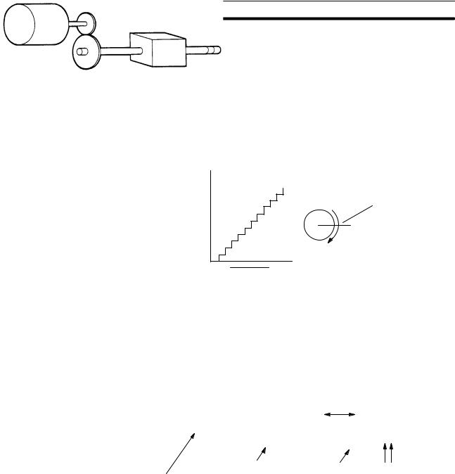
Angle of rotation
Angle of rotation
Positioning output
1 2 |
n |
Positioning pulses
1-4-3 Basic Positioning System Design
The following diagram and parameters illustrate a simplified positioning system. M : Reduction ratio
P : Feed screw pitch (mm/revolution)
V : Feed velocity of object being positioned (mm/s) θs: Stepping angle per pulse (degree/pulse)
N V
Reduction gear |
M |
Object being |
Feed screw pitch |
Stepping motor |
|
positioned |
P |
|
|
|
The positioning accuracy in mm/pulse is computed as follows:
Positioning accuracy |
= P/(pulses per revolution x M) |
|
= P/((360/ θs) x M)) |
|
= (P x θs)/(360 x M) |
The required pulse frequency from the PCU (pulses/second) is computed as follows:
Pulse frequency |
= V/Positioning accuracy |
|
= (360 x M x V)/(P x θs) |
And the required number of pulses to feed an object by a distance L in mm is computed as follows:
Number of pulses |
= L/Positioning accuracy |
|
= (360 x M x L)/(P x θs) |
12
Exchanging Data |
Section 1-5 |
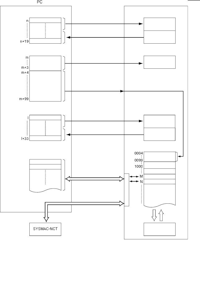
1-5 Exchanging Data
The Position Control Unit exchanges data with the Programmable Controller as shown in the following diagram. This explanation is provided using the C200HW-NC413 as an example. The size of the allocated areas differs with the NC113 and NC213. For details regarding the data areas for the various PCUs, refer to Section 4 Data Areas.
Operating Memory Area
IR area
|
Parameter area |
|
Common |
DM area |
parameters |
|
|
|
Axis parameters |
Operating Data Area
DM or EM area
Data transfer area
DM or EM area Address M data
Address N data
|
PCU |
|
I/O refresh |
Command |
|
|
||
(Operation commands, data |
interpretation |
|
|
||
transfer commands, etc.) |
|
|
I/O refresh (PCU status) |
Status |
|
|
||
At power-up or restart |
Common |
|
|
||
(Common parameters) |
parameters |
|
|
||
At power-up or restart |
|
|
(Axis parameters) |
|
|
I/O refresh |
Data transfer and |
|
operation command |
||
(Data transfer and operation |
||
information |
||
command information) |
|
|
I/O refresh (PCU status) |
Status |
|
|
||
Address |
Internal memory |
|
|
Axis parameters |
|
When data transfer |
|
|
commands are executed. |
|
|
When IOWR or IORD is |
|
|
executed. |
|
(Data for positioning)
When data is transferred
Saving |
Power-up |
data |
or restart |
|
Flash memory |
13

Exchanging Data |
Section 1-5 |
Note The axis parameter data stored in addresses 0004 to 0099 can be transferred from words (m+4) through (m+99) of the DM area, and data can also be transferred for the data transfer area at the Programmable Controller. Moreover, data can be saved to the flash memory.
1-5-1 Explanation
Operating Memory Area
(IR Area)
The explanations provided here use the C200HW-NC413 PCU as an example. With the NC213 and NC113, the sizes of the various areas differ depending on the number of axes. For details, refer to Section 4 Data Areas.
The PCU occupies 20 words of the Special I/O area within the Programmable Controller’s IR area. Of these, eight words are used during I/O refreshing for outputting information related to instructions for operations such as transferring data from the Programmable Controller to the PCU. The remaining 12 words are used for inputting the PCU’s status during I/O refreshing.
Parameter Area |
The PCU occupies 100 words of the Special I/O Unit data area within the Pro- |
(DM Area) |
grammable Controller’s DM area. When the PCU is powered up or restarted, |
|
common parameters and axis parameters related to control are transferred to |
|
the PCU. The axis parameters are stored in the PCU’s internal RAM by address. |
|
It is also possible, when the PCU is powered up or restarted, to use axis parame- |
|
ters previously stored in the PCU’s internal flash memory, without having them |
|
transferred from the Programmable Controller. The selection as to which of |
|
these two methods to use is made by a common parameter setting. For details, |
|
refer to 4-2 Common Parameter Area. |
Note |
The common parameter area settings are required when the PCU is used. If |
|
these settings are not made, a common parameter error (error codes 0010 to |
|
0013) will be generated. |
Operating Data Area |
Depending on a common parameters setting, 34 words are reserved in the Pro- |
|
grammable Controller’s data areas. Of these, 26 words are used during I/O |
|
refreshing for outputting information related to data transfers from the Program- |
|
mable Controller to the PCU, and information used for operations. The remain- |
|
ing eight words are used for inputting the PCU’s status during I/O refreshing. |
Data Transfer Area |
When data is transferred according to the data transfer information set in the |
|
operating data area, only the portion of data transferred is used. When the data |
|
transfer instructions, Intelligent I/O Write (IOWR) and Intelligent I/O Read |
|
(IORD), are executed, the positioning data is transferred to the PCU. |
Internal Memory and
Flash Memory
Data in internal memory can be saved to flash memory by executing a data save instruction from the Programmable Controller. The saved data is automatically written to the internal memory when the PCU is powered up or restarted. However, whether axis parameters are read from the parameter area (DM) or from flash memory is determined by a common parameters setting.
14
Before Operation |
Section 1-6 |
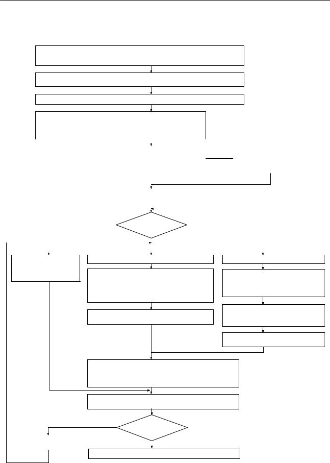
1-6 Before Operation
Wiring external inputs. (Refer to Section 2 Specifications and Wiring.)
Wire the origin input signal, origin proximity input signal, CW and CCW limit input signals, emergency stop input signal, and interrupt input signal.
Wiring the motor and motor driver.
Wire the motor and motor driver as described in the installation manual.
Wiring the motor driver and PCU. (Refer to Section 2 Specifications and Wiring.)
Setting common parameters. (Refer to 4-2 Common Parameter Area.) (See note 1.)
Set the operating data area, the mounting position, and the parameters.
|
|
|
|
|
|
|
|
|
|
|
|
|
|
|
|
|
|
|
|
|
|
|
|
|
|
|
Saving axis parameters. |
|
|
|
|
Setting axis parameters. (Refer to 4-3 Axis Parameter Area.) (See |
|
|||||||||||
|
|
|
|
|
|
(Refer to 5-7 Saving Data.) |
|
|||||||
|
|
note 2.) |
|
|
|
|
|
If setting axis parameters by |
|
|||||
|
|
Set the data required for PCU control, the I/O settings, the opera- |
|
|
|
|
means of a data transfer, save |
|
||||||
|
|
tion mode, the origin search method, the origin search speed, the |
|
|
|
|
the settings to flash memory. |
|
||||||
|
|
acceleration/deceleration curve, the CW and CCW limit signals, etc. |
|
|
|
|
|
|
|
|||||
|
|
|
|
|
|
|
|
|
||||||
|
|
|
|
|
|
|
|
|
|
|
|
|
|
|
|
|
|
|
|
|
|
|
|
|
|
|
|
|
|
|
|
Re-powering or restarting the PCU. (See note 5.) |
|
|
|
|
|
|
|
|
||||
|
|
The common and axis parameter settings will go into effect. |
|
|
|
|
|
|
|
|
||||
|
|
|
|
|
|
|
|
|
|
|
|
|
|
|
|
|
|
|
|
|
|
|
|
|
|
|
|
|
|
|
|
|
|
|
|
|
ON |
|
|
|
|
|
|
|
|
|
|
|
|
Busy Flag |
|
|
|
|
|
|
|
||
|
|
|
|
|
|
|
|
|
|
|
|
|
||
|
|
|
|
|
(See note 6.) |
|
|
|
|
|
|
|
|
|
|
|
|
|
|
|
OFF |
|
|
|
|
|
|
|
|
|
|
|
|
|
|
|
|
|
|
|
|
|
|
|
|
|
|
|
|
|
|
|
|
|
|
|
|
|
|
|
|
|
|
|
|
|
|
|
|
|
|
|
|
|
Interrupt feeding and other operations.
(Refer to Section 9
Other Operations.)
(When using direct operation.)
Setting the operating data area.
(Refer to 4-1 Overall Structure, 4-5 Operating
Data Area)
Set the positions, speeds, and acceleration/deceleration times
Creating the ladder program.
(Refer to Section 7 Direct Operation.)
(When using memory operation.)
Transferring data. (Refer to Section 5
Transferring and Saving Data.) Transfer to the PCU the data to be used for memory operation.
Saving the data (Refer to 5-1 Transferring and Saving Data, 5-7 Saving
Data.) (See note 3.)
Creating the ladder program.
(Refer to Section 8 Memory Operation.)
Origin search. (Refer to Section 6 Defining the Origin.) (See note 4.)
Executing direct operation, memory operation (Refer to
Section 7 Direct Operation, Section 8 Memory Operation.)
Trial operation, debugging. (Refer to Section 11 Troubleshooting.) (See note 5.)
NG
Trial operation (See note 5.)
Correcting the data and |
|
|
OK |
|
|||
the ladder program. |
|
|
|
|
|
|
|
|
|
|
|
Operation. (Refer to Section 11 Troubleshooting.)
Note 1. These settings are required when first using the PCU, or when changing the operating data area, the mounting position, or the parameter settings.
15

Before Operation |
Section 1-6 |
2.The user can select whether to use the axis parameters set in Data Memory or the axis parameters saved at the PCU.
3.All saved data is automatically read to the PCU’s internal memory when the PCU is powered up. If the common parameters are set so that data saved at the PCU is used, then the axis parameters will be automatically read at pow- er-up.
4.For operations that cannot be performed when the origin is not established, it will be necessary to first execute an origin search or a present position change to establish the origin.
5.For the operational flow when an error or alarm is generated, refer to Section 11 Troubleshooting.
6.When powering up or restarting the PCU, wait for the X-axis Busy Flag to turn OFF before executing any commands.
16
SECTION 2
Specifications and Wiring
This section provides the Position Control Unit’s specifications and explains the wiring.
2-1 |
Specifications . . . . . . . . . . . . . . . . . . . . . . . . . . . . . . . . . . . . . . . . . . . . . . . . . . . . . . . . . . . . |
18 |
|
|
2-1-1 |
General Specifications . . . . . . . . . . . . . . . . . . . . . . . . . . . . . . . . . . . . . . . . . . . . . . |
18 |
|
2-1-2 Operations and Performance Specifications . . . . . . . . . . . . . . . . . . . . . . . . . . . . . |
18 |
|
|
2-1-3 |
I/O Electrical Specifications . . . . . . . . . . . . . . . . . . . . . . . . . . . . . . . . . . . . . . . . . |
19 |
|
2-1-4 |
Dimensions (Unit: mm) . . . . . . . . . . . . . . . . . . . . . . . . . . . . . . . . . . . . . . . . . . . . . |
20 |
2-2 |
Components . . . . . . . . . . . . . . . . . . . . . . . . . . . . . . . . . . . . . . . . . . . . . . . . . . . . . . . . . . . . . |
21 |
|
2-3 |
External I/O Circuitry . . . . . . . . . . . . . . . . . . . . . . . . . . . . . . . . . . . . . . . . . . . . . . . . . . . . . |
24 |
|
|
2-3-1 |
Connector Pin Arrangement . . . . . . . . . . . . . . . . . . . . . . . . . . . . . . . . . . . . . . . . . |
24 |
|
2-3-2 External I/O Connector Arrangement . . . . . . . . . . . . . . . . . . . . . . . . . . . . . . . . . . |
25 |
|
|
2-3-3 |
I/O Circuitry . . . . . . . . . . . . . . . . . . . . . . . . . . . . . . . . . . . . . . . . . . . . . . . . . . . . . . |
27 |
2-4 |
Connecting External I/O . . . . . . . . . . . . . . . . . . . . . . . . . . . . . . . . . . . . . . . . . . . . . . . . . . . |
30 |
|
|
2-4-1 |
Output Connection Examples . . . . . . . . . . . . . . . . . . . . . . . . . . . . . . . . . . . . . . . . |
30 |
|
2-4-2 |
Input Connection Examples . . . . . . . . . . . . . . . . . . . . . . . . . . . . . . . . . . . . . . . . . . |
33 |
|
2-4-3 Connecting Origin and Positioning Completed Input Signals . . . . . . . . . . . . . . . . |
35 |
|
|
2-4-4 |
Wiring Precautions . . . . . . . . . . . . . . . . . . . . . . . . . . . . . . . . . . . . . . . . . . . . . . . . . |
36 |
2-5 Connections in Each Operating Mode . . . . . . . . . . . . . . . . . . . . . . . . . . . . . . . . . . . . . . . . . |
37 |
||
2-6 Connection of Unused Axes . . . . . . . . . . . . . . . . . . . . . . . . . . . . . . . . . . . . . . . . . . . . . . . . . |
45 |
||
|
2-6-1 C200HW-NC213 – X Axis Only . . . . . . . . . . . . . . . . . . . . . . . . . . . . . . . . . . . . . . |
45 |
|
2-7 |
Servo Relay Unit . . . . . . . . . . . . . . . . . . . . . . . . . . . . . . . . . . . . . . . . . . . . . . . . . . . . . . . . . |
45 |
|
17
 Loading...