


 Loading...
Cat. No. F04E-EN-02
Safety Light Curtain Type 4
MS4800E
OPERATION MANUAL
MS4800E
Safety Light Curtain Type 4
Installation and Operating Manual
March 2010
Omron Europe B.V. Wegalaan 67-69 NL-2132 JD, Hoofddorp Pays-Bas
Tel.: +31 (0) 23 568 13 00 Fax: +31 (0) 23 568 13 88 www.industrial.omron.eu
iv
Notice:
OMRON products are manufactured for use according to proper procedures by a qualified operator and only for the purposes described in this manual.
The following conventions are used to indicate and classify precautions in this manual. Always heed the information provided with them. Failure to heed precautions can result in injury to people or damage to property.
!DANGER Indicates an imminently hazardous situation which, if not avoided, will result in death or serious injury.
!WARNING Indicates a potentially hazardous situation which, if not avoided, could result in death or serious injury.
!Caution Indicates a potentially hazardous situation which, if not avoided, may result in minor or moderate injury, or property damage.
OMRON Product References
All OMRON products are capitalized in this manual. The word “Unit” is also capitalized when it refers to an OMRON product, regardless of whether or not it appears in the proper name of the product.
Visual Aids
The following headings appear in the left column of the manual to help you locate different types of information.
Note Indicates information of particular interest for efficient and convenient operation of the product.
1,2,3... 1. Indicates lists of one sort or another, such as procedures, checklists, etc.
♥ OMRON, 2010
All rights reserved. No part of this publication may be reproduced, stored in a retrieval system, or transmitted, in any form, or by any means, mechanical, electronic, photocopying, recording, or otherwise, without the prior written permission of OMRON.
No patent liability is assumed with respect to the use of the information contained herein. Moreover, because OMRON is constantly striving to improve its high-quality products, the information contained in this manual is subject to change without notice. Every precaution has been taken in the preparation of this manual. Nevertheless, OMRON assumes no responsibility for errors or omissions. Neither is any liability assumed for damages resulting from the use of the information contained in this publication.
v
vi
TABLE OF CONTENTS
PRECAUTIONS . . . . . . . . . . . . . . . . . . . . . . . . . . . . . . . . . . . |
xiii |
|
1 |
Precautions on Safety . . . . . . . . . . . . . . . . . . . . . . . . . . . . . . . . . . . . . . . . . . . . . . . . . . . . . . |
xiii |
2 Alert Statements in this manual. . . . . . . . . . . . . . . . . . . . . . . . . . . . . . . . . . . . . . . . . . . . . . . |
xiii |
|
3 Precautions for Safe Use . . . . . . . . . . . . . . . . . . . . . . . . . . . . . . . . . . . . . . . . . . . . . . . . . . . . |
xvii |
|
4 Precautions for Correct Use. . . . . . . . . . . . . . . . . . . . . . . . . . . . . . . . . . . . . . . . . . . . . . . . . . |
xviii |
|
SECTION 1 |
|
|
Important Safety Warnings . . . . . . . . . . . . . . . . . . . . . . . . . . |
1 |
|
SECTION 2 |
|
|
Product features . . . . . . . . . . . . . . . . . . . . . . . . . . . . . . . . . . . |
3 |
|
SECTION 3 |
|
|
System Components and Indicators . . . . . . . . . . . . . . . . . . . |
4 |
|
SECTION 4 |
|
|
System Operation . . . . . . . . . . . . . . . . . . . . . . . . . . . . . . . . . . |
5 |
|
4-1 |
Operating States. . . . . . . . . . . . . . . . . . . . . . . . . . . . . . . . . . . . . . . . . . . . . . . . . . . . . . . . . . . |
5 |
4-2 |
Operating Modes . . . . . . . . . . . . . . . . . . . . . . . . . . . . . . . . . . . . . . . . . . . . . . . . . . . . . . . . . . |
6 |
4-3 |
MS4800FS Cascaded Series . . . . . . . . . . . . . . . . . . . . . . . . . . . . . . . . . . . . . . . . . . . . . . . . . |
6 |
SECTION 5 |
|
|
Detection Options . . . . . . . . . . . . . . . . . . . . . . . . . . . . . . . . . . |
9 |
|
5-1 |
Fixed Blanking . . . . . . . . . . . . . . . . . . . . . . . . . . . . . . . . . . . . . . . . . . . . . . . . . . . . . . . . . . . |
9 |
5-2 |
Floating Blanking . . . . . . . . . . . . . . . . . . . . . . . . . . . . . . . . . . . . . . . . . . . . . . . . . . . . . . . . . |
13 |
5-3 Fixed Blanking with Floating Blanking . . . . . . . . . . . . . . . . . . . . . . . . . . . . . . . . . . . . . . . . |
14 |
|
5-4 |
Optical Synchronization . . . . . . . . . . . . . . . . . . . . . . . . . . . . . . . . . . . . . . . . . . . . . . . . . . . . |
15 |
SECTION 6 |
|
|
Diagnostic and Test Features. . . . . . . . . . . . . . . . . . . . . . . . . |
17 |
|
6-1 Individual Beam Indicators (IBI). . . . . . . . . . . . . . . . . . . . . . . . . . . . . . . . . . . . . . . . . . . . . . |
17 |
|
6-2 External Device Monitoring (EDM) . . . . . . . . . . . . . . . . . . . . . . . . . . . . . . . . . . . . . . . . . . . |
17 |
|
6-3 Machine test signal (MTS) . . . . . . . . . . . . . . . . . . . . . . . . . . . . . . . . . . . . . . . . . . . . . . . . . . |
17 |
|
6-4 |
Range selection . . . . . . . . . . . . . . . . . . . . . . . . . . . . . . . . . . . . . . . . . . . . . . . . . . . . . . . . . . . |
17 |
6-5 |
Start/Restart Input . . . . . . . . . . . . . . . . . . . . . . . . . . . . . . . . . . . . . . . . . . . . . . . . . . . . . . . . . |
18 |
vii
SECTION 7 |
|
|
Using selector switches to set features. . . . . . . . . . . . . . . . . . |
19 |
|
7-1 |
Access to the selector switches . . . . . . . . . . . . . . . . . . . . . . . . . . . . . . . . . . . . . . . . . . . . . . . |
19 |
7-2 |
Operating mode selection . . . . . . . . . . . . . . . . . . . . . . . . . . . . . . . . . . . . . . . . . . . . . . . . . . . |
20 |
7-3 |
Selecting and programming Fixed Blanking . . . . . . . . . . . . . . . . . . . . . . . . . . . . . . . . . . . . . |
20 |
7-4 |
Selecting and programming Floating Blanking. . . . . . . . . . . . . . . . . . . . . . . . . . . . . . . . . . . |
20 |
7-5 |
Selecting External Device Monitoring (EDM) . . . . . . . . . . . . . . . . . . . . . . . . . . . . . . . . . . . |
20 |
7-6 |
Selecting Machine Test Signal (MTS). . . . . . . . . . . . . . . . . . . . . . . . . . . . . . . . . . . . . . . . . . |
20 |
7-7 |
Selecting Scan Codes. . . . . . . . . . . . . . . . . . . . . . . . . . . . . . . . . . . . . . . . . . . . . . . . . . . . . . . |
21 |
SECTION 8 |
|
|
Outputs . . . . . . . . . . . . . . . . . . . . . . . . . . . . . . . . . . . . . . . . . . |
23 |
|
8-1 |
Safety Outputs (OSSDs) . . . . . . . . . . . . . . . . . . . . . . . . . . . . . . . . . . . . . . . . . . . . . . . . . . . . |
23 |
8-2 |
Auxiliary Output . . . . . . . . . . . . . . . . . . . . . . . . . . . . . . . . . . . . . . . . . . . . . . . . . . . . . . . . . . |
23 |
SECTION 9 |
|
|
Safe Mounting Distances . . . . . . . . . . . . . . . . . . . . . . . . . . . . |
25 |
|
9-1 |
Safety distance for safeguarding danger points . . . . . . . . . . . . . . . . . . . . . . . . . . . . . . . . . . . |
25 |
9-2 |
Safety distance for safeguarding danger areas. . . . . . . . . . . . . . . . . . . . . . . . . . . . . . . . . . . . |
27 |
9-3 |
Safety distance and beam heights in access guarding . . . . . . . . . . . . . . . . . . . . . . . . . . . . . . |
28 |
SECTION 10 |
|
|
Installation. . . . . . . . . . . . . . . . . . . . . . . . . . . . . . . . . . . . . . . . |
29 |
|
10-1 |
Reflective Surface Interference . . . . . . . . . . . . . . . . . . . . . . . . . . . . . . . . . . . . . . . . . . . . . . . |
29 |
10-2 |
Cross Talk Mitigation . . . . . . . . . . . . . . . . . . . . . . . . . . . . . . . . . . . . . . . . . . . . . . . . . . . . . . |
30 |
10-3 |
General Mounting Considerations. . . . . . . . . . . . . . . . . . . . . . . . . . . . . . . . . . . . . . . . . . . . . |
31 |
SECTION 11 |
|
|
Connection to the Machine Control Circuit. . . . . . . . . . . . . |
35 |
|
11-1 |
Interconnect cables for cascaded MS4800FS system . . . . . . . . . . . . . . . . . . . . . . . . . . . . . . |
36 |
11-2 |
Connection to two forcibly guided relays . . . . . . . . . . . . . . . . . . . . . . . . . . . . . . . . . . . . . . . |
37 |
11-3 |
Connection to a safety relay unit . . . . . . . . . . . . . . . . . . . . . . . . . . . . . . . . . . . . . . . . . . . . . . |
37 |
SECTION 12 |
|
|
Muting . . . . . . . . . . . . . . . . . . . . . . . . . . . . . . . . . . . . . . . . . . . |
39 |
|
12-1 |
Muting Controller RM-6 . . . . . . . . . . . . . . . . . . . . . . . . . . . . . . . . . . . . . . . . . . . . . . . . . . . . |
39 |
SECTION 13 |
|
|
Checkout and test procedure . . . . . . . . . . . . . . . . . . . . . . . . . |
41 |
|
13-1 |
Checkout Procedure. . . . . . . . . . . . . . . . . . . . . . . . . . . . . . . . . . . . . . . . . . . . . . . . . . . . . . . . |
41 |
13-2 |
Test Procedure . . . . . . . . . . . . . . . . . . . . . . . . . . . . . . . . . . . . . . . . . . . . . . . . . . . . . . . . . . . . |
41 |
13-3 Using the test object. . . . . . . . . . . . . . . . . . . . . . . . . . . . . . . . . . . . . . . . . . . . . . . . . . . . . . . . |
41 |
|
viii
SECTION 14 |
|
|
Cleaning. . . . . . . . . . . . . . . . . . . . . . . . . . . . . . . . . . . . . . . . . . |
43 |
|
SECTION 15 |
|
|
Specifications and additional information . . . . . . . . . . . . . . |
45 |
|
15-1 |
System Specification. . . . . . . . . . . . . . . . . . . . . . . . . . . . . . . . . . . . . . . . . . . . . . . . . . . . . . . |
45 |
15-2 MS4800 system Dimensional Drawing . . . . . . . . . . . . . . . . . . . . . . . . . . . . . . . . . . . . . . . . |
48 |
|
15-3 MS4800 system data with 14 mm resolution . . . . . . . . . . . . . . . . . . . . . . . . . . . . . . . . . . . . |
49 |
|
15-4 MS4800 system data with 30 mm resolution . . . . . . . . . . . . . . . . . . . . . . . . . . . . . . . . . . . . |
50 |
|
15-5 MS4800FS system Dimensional Drawing . . . . . . . . . . . . . . . . . . . . . . . . . . . . . . . . . . . . . . |
52 |
|
15-6 MS4800FS system data with 14 mm resolution . . . . . . . . . . . . . . . . . . . . . . . . . . . . . . . . . . |
53 |
|
15-7 MS4800FS system data with 30 mm resolution . . . . . . . . . . . . . . . . . . . . . . . . . . . . . . . . . . |
54 |
|
15-8 |
List of models . . . . . . . . . . . . . . . . . . . . . . . . . . . . . . . . . . . . . . . . . . . . . . . . . . . . . . . . . . . . |
57 |
15-9 |
Accessories . . . . . . . . . . . . . . . . . . . . . . . . . . . . . . . . . . . . . . . . . . . . . . . . . . . . . . . . . . . . . . |
67 |
SECTION 16 |
|
|
Glossary . . . . . . . . . . . . . . . . . . . . . . . . . . . . . . . . . . . . . . . . . . |
71 |
|
SECTION 17 |
|
|
Diagnostics and Troubleshooting . . . . . . . . . . . . . . . . . . . . . |
73 |
|
17-1 Transmitter Diagnostic information and troubleshooting . . . . . . . . . . . . . . . . . . . . . . . . . . . |
73 |
|
17-2 |
Receiver Diagnostic Information . . . . . . . . . . . . . . . . . . . . . . . . . . . . . . . . . . . . . . . . . . . . . |
73 |
17-3 Receiver Endcap Indicator Lights. . . . . . . . . . . . . . . . . . . . . . . . . . . . . . . . . . . . . . . . . . . . . |
73 |
|
17-4 |
Receiver Troubleshooting . . . . . . . . . . . . . . . . . . . . . . . . . . . . . . . . . . . . . . . . . . . . . . . . . . . |
74 |
17-5 |
Receiver Error Codes . . . . . . . . . . . . . . . . . . . . . . . . . . . . . . . . . . . . . . . . . . . . . . . . . . . . . . |
74 |
17-6 |
FAQ . . . . . . . . . . . . . . . . . . . . . . . . . . . . . . . . . . . . . . . . . . . . . . . . . . . . . . . . . . . . . . . . . . . . |
76 |
SECTION 18 |
|
|
Appendix . . . . . . . . . . . . . . . . . . . . . . . . . . . . . . . . . . . . . . . . . |
77 |
|
18-1 |
Appendix A . . . . . . . . . . . . . . . . . . . . . . . . . . . . . . . . . . . . . . . . . . . . . . . . . . . . . . . . . . . . . . |
77 |
18-2 |
Appendix B . . . . . . . . . . . . . . . . . . . . . . . . . . . . . . . . . . . . . . . . . . . . . . . . . . . . . . . . . . . . . . |
78 |
18-3 EC Declaration of Conformity . . . . . . . . . . . . . . . . . . . . . . . . . . . . . . . . . . . . . . . . . . . . . . . |
79 |
|
Revision History . . . . . . . . . . . . . . . . . . . . . . . . . . . . . . . . . . . |
80 |
|
ix
Introduction
Thank you for purchasing the MS4800 series Safety Light Curtain. This is the instruction manual describing the use of the MS4800 system.
Important notice
This manual provides installation and operating information on the following models:
|
Basic |
Advanced |
|
|
|
Resolution 14 mm, standalone |
MS4800S-EB-014 |
MS4800S-EA-014 |
|
|
|
Resolution 14 mm, cascadable |
MS4800FS-EB-014 |
MS4800FS-EA-014 |
|
|
|
Resolution 30 mm, standalone |
MS4800S-EB-030 |
MS4800S-EA-030 |
|
|
|
Resolution 30 mm, cascadable |
MS4800FS-EB-030 |
MS4800FS-EA-030 |
|
|
|
Where information is common on all models the term "MS4800 system" will be used. Where information is given for a specific model the model number will be used.
Always heed the following points when using the MS4800 system:
1.Be sure to have MS4800 system handled by a "Responsible Person" who is well aware of and familiar with the machine to be installed.
2.The term "Responsible Person" used in this Instruction manual means the person qualified, authorized and responsible to secure "safety" in each process of the design, installation, operation, maintenance services and disposition of the machine.
3.It is assumed that MS4800 system will be used properly according to the installation environment, performance and function of the machine. Responsible Person should conduct risk assessment on the machine and determine the suitability of this product before installation.
4.Read this Manual thoroughly to understand and make good use of the descriptions before installing and operating the product.
5.Keep this Manual at the place where the operator can refer to whenever necessary.
x
Read and understand this document
Please read and understand this document before using the products. Please consult your OMRON representative if you have any questions or comments.
WARRANTY
OMRON's exclusive warranty is that the products are free from defects in materials and workmanship for a period of one year (or other period if specified) from date of sale by OMRON.
OMRON MAKES NO WARRANTY OR REPRESENTATION, EXPRESS OR IMPLIED, REGARDING NON-INFRINGEMENT, MERCHANTABILITY, OR FITNESS FOR PARTICULAR PURPOSE OF THE PRODUCTS, ANY BUYER OR USER ACKNOWLEDGES THAT THE BUYER OR USER ALONE HAS DETERMINED THAT THE PRODUCTS WILL SUITABLY MEET THE REQUIREMENTS OR THEIR INTENDED USE. OMRON DISCLAIMS ALL OTHER WARRANTIES, EXPRESS OR IMPLIED.
LIMITATIONS OF LIABILITY
OMRON SHALL NOT BE RESPONSIBLE FOR SPECIAL, INDIRECT, OR CONSEQUENTIAL DAMAGES, LOSS OF PROFITS OR COMMERCIAL LOSS IN ANY WAY CONNECTED WITH THE PRODUCTS, WHETHER SUCH CLAIM IS BASED ON CONTRACT, WARRANTY, NEGLIGENCE, OR STRICT LIABILITY.
In no event shall responsibility of OMRON for any act exceed the individual price of the product on which liability asserted.
IN NO EVENT SHALL OMRON BE RESPONSIBLE FOR WARRANTY, REPAIR, OR OTHER CLAIMS REGARDING THE PRODUCTS UNLESS OMRON'S ANALYSIS CONFIRMS THAT THE PRODUCTS WERE PROPERLY HANDLED, STORED, INSTALLED, AND MAINTAINED AND NOT SUBJECT TO CONTAMINTAION, ABUSE, MISUSE, OR INAPPROPRIATE MODIFICATION OR REPAIR.
SUITABILITY FOR USE
OMRON shall not be responsible for conformity with any standards, codes, or regulations that apply to the combination of products in the customer's application or use of the product.
At the customer's request, OMRON will provide applicable third party certification documents identifying ratings and limitations of use that apply to the products. This information by itself is not sufficient for a complete determination of the suitability of the products in combination with the end product, machine, system, or other application or use.
The following are some examples of applications for which particular attention must be given. This is not intended to be an exhaustive list of all possible uses of the products, nor is it intended to imply that the uses listed may be suitable for the products:
Outdoor use, uses involving potential chemical contamination or electrical interference, or conditions or uses not described in this document.
Nuclear energy control systems, combustion systems, railroad systems, aviation systems, medical equipment, amusement machines, vehicles, and installations subject to separate industry or government regulations.
Systems, machines, and equipment that could present a risk to life or property.
Please know and observe all prohibitions of use applicable to the products.
NEVER USE THE PRODUCTS FOR AN APPLICATION INVOLVING SERIOUS RISK TO LIFE OR PROPERTY WITHOUT ENSURING THAT THE SYSTEM AS A WHOLE HAS BEEN DESIGNED TO ADDRESS THE RISKS, AND THAT THE OMRON PRODUCT IS PROPERLY RATED AND INSTALLED FOR THE INTENDED USE WITHIN THE OVERALL EQUIPMENT OR SYSTEM.
PERFORMANCE DATA
Performance data given in this document is provided as a guide for the user in determining suitability and does not constitute a warranty. It may represent the result of OMRON's test conditions, and the users must correlate it to actual application requirements. Actual performance is subject to the OMRON Warranty and Limitations of Liability.
xi
CHANGE IN SPECIFICATIONS
Product specifications and accessories may be changed at any time based on improvements and other reasons.
It is our practice to change model numbers when published ratings or features are changed, or when significant construction changes are made. However, some specifications of the product may be changed without any notice. When in doubt, special model numbers may be assigned to fix or establish key specifications for your application on your request. Please consult with your OMRON representative at any time to confirm actual specifications of purchased products.
DIMENSIONS AND WEIGHTS
Dimensions and weights are nominal and are not to be used for manufacturing purposes, even when tolerances are shown.
ERRORS AND OMISSIONS
The information in this document has been carefully checked and is believed to be accurate; however, no responsibility is assumed for clerical, typographical, or proofreading errors, or omissions.
PROGRAMMABLE PRODUCTS
OMRON shall not be responsible for the user's programming of a programmable product, or any consequence thereof.
COPYRIGHT AND COPY PERMISSION
This document shall not be copied for sales or promotions without permission.
This document is protected by copyright and is intended solely for use in conjunction with the product. Please notify us before copying or reproducing this document in any manner, for any other purpose. If copying or transmitting this document to another, please copy or transmit it in its entirety.
xii
PRECAUTIONS
1 Precautions on Safety
In order to use the MS4800 system safely, the precautions listed in this manual indicated by alert symbols and descriptions must be followed. Failure to follow all precautions and alerts may result in an unsafe use or operation.
The following indications and symbols are used for the application:
!WARNING This sign indicates a potentially hazardous situation which, if not avoided, will result in minor or moderate injury, or may result in serious injury or death. Additionally there may be significant property damage.
2 Alert Statements in this manual
2-1 For users
!WARNING The MS4800 system must be installed, configured, and incorporated into a machine control system by a sufficiently trained and qualified person. An unqualified person may not be able to perform these operations properly, which may cause a person to go undetected, resulting in serious injury.
!WARNING When changes are made to each function using the selector switches, the administrator must manage the detail of the changes and perform the changes. Accidental functional setting change may cause failure of human body detection, resulting in a serious injury.
2-2 For machines
!WARNING Do not use this sensor for machines that cannot be stopped by electrical control. For example, do not use it for a pressing machine that uses full-rotation clutch. Otherwise, the machine may not stop before a person reaches the hazardous part, resulting in serious injury.
!WARNING Do not use the auxiliary output or external indicator output for safety applications. Human body may not be detected when MS4800 system fails, resulting in serious injury.
2-3 For installations
!WARNING After unpacking and before installing the MS4800 system please check the mechanical condition of the system carefully. Do not install a mechanically damaged product. Return this to your OMRON service for inspection or repair. Failure to do so may result in serious injury.
!WARNING Do not drop the products. Dropping the products may lead to internal or external damage. Please return a MS4800 system that was dropped on the floor to your OMRON service for inspection or repair. Failure to do so may result in serious injury.
!WARNING Make sure to test the operation of the MS4800 system after installation to verify that the MS4800 system operates as intended. Make sure to stop the machine until the test is complete. Unintended function settings may cause a person to go undetected, resulting in serious injury.
xiii

Alert Statements in this manual |
2 |
!WARNING Make sure to install the MS4800 system at the safe distance from the hazardous part of the equipment. Otherwise, the machine may not stop before a person reaches the hazardous part, resulting in serous injury.
!WARNING Install a protective structure so that the hazardous part of a machine can only be reached by passing through the sensor's detection zone. Install the sensors so that part of the person is always present in the detection zone when working in a machine's hazardous areas. If a person is able to step into the hazardous area of a machine and remain behind the MS4800 system's detection zone, configure the system with an interlock function that prevents the machine from being restarted. Failure to do so may result in serious injury.
!WARNING Install the interlock reset switch in a location that provides a clear view of the entire hazardous area and where it cannot be activated from within the hazardous area.
!WARNING The MS4800 system cannot protect a person from a projectile exiting the hazardous zone. Install protective cover(s) or fence(s).
!WARNING To prevent personnel approach to dangerous part of the machine through a zone disabled by the fixed blanking function, you must install a protective structure to cover the whole disabled zone. Failure to do so may cause failure of human body detection, resulting in a serious injury.
!WARNING You must ensure that a test rod is detected for all detection zones except where fixed or floating blanking function is used. Failure to do so may cause failure of human body detection, resulting in a serious injury.
!WARNING Detection capability gets larger if fixed or floating blanking function is used. You must use the detection capability for fixed and floating blanking functions. Failure to do so may cause failure of machine stop before reaching the machine's dangerous part, resulting in a serious injury.
!WARNING The muting and override functions disable the safety functions of the device. You must ensure safety using other method when these functions are operating.
!WARNING Install muting sensors so that they can distinguish between the object that is being allowed to pass through the detection zone and a person. If the muting function is activated by the detection of a person, it may result in serious injury.
!WARNING Muting lamps (external indicators) that indicate the state of the muting and override functions must be installed where they are clearly visible to workers from all the operating positions.
!WARNING Muting related time must be properly configured for its application by a sufficiently trained and qualified person, and the person must have responsibility for settings, especially when setting the muting time limit to infinite.
!WARNING Use independent 2 input devices for muting inputs.
!WARNING You must install MS4800 system muting sensor, and physical barrier, and configure time settings for muting so that an operator should not enter hazardous zone.
xiv

Alert Statements in this manual |
2 |
!WARNING Install the switch that activates the override in a location that provides a clear view of the entire hazardous area and where it cannot be activated from within the hazardous area. Make sure that nobody is in the hazardous area before activating the override function.
!WARNING Do not place fluorescent lights within the effective aperture angle of the receiver, as it may influence the MS4800 system under certain circumstances.
!WARNING Install the sensor system so that it is not affected by any reflective surfaces. Failure to do so may hinder detection, resulting in serious injury.
!WARNING When using more than 1 set of MS4800 system, install them so that mutual interference does not occur, such as by configuring series connections or using physical barriers between adjacent sets.
!WARNING Make sure that the MS4800 system is securely mounted and its cables and connectors are properly connected.
!WARNING Make sure that foreign objects such as water, oil, or dust do not enter the inside of the MS4800 system while the cover for the selector switches is open and tighten the screws of the cover firmly after changing the settings.
!WARNING Do not use the sensor system with mirrors in a retro-reflective configuration. Doing so may hinder detection. It is possible to use mirrors to "bend" the detection zone to a 90° angle.
!WARNING Perform an inspection for all MS4800 systems as described in the chapter "Checkout and test procedure". When using series connections, perform inspections for every connected MS4800 system.
2-4 For wiring
!WARNING Connect the load between the output and 0V line (PNP output). Connecting the load between the output and +24 V line will result in a dangerous condition because operation is reversed to "ON when blocked".
!WARNING Do not short-circuit the output line to the +24 V line. Otherwise, the output is always ON. Also, the 0 V of the power supply must be grounded so that output does not turn ON due to grounding of the output line.
!WARNING Configure the system by using the optimal number of safety outputs that satisfy the requirements of the necessary safety category.
!WARNING Do not connect each line of MS4800 system to a DC power supply of more than 24 VDC+20%. Also, do not connect to an AC power supply. Failure to do so may result in electric shock.
xv

Alert Statements in this manual |
2 |
!WARNING For the MS4800 system to comply with IEC 61496-1 and UL 508, the DC power supply unit must satisfy all of thefollowing conditions:
•Must be within the rated power voltage (24 V DC ± 20%)
•Must have tolerance against the total rated current of devices if it is connected to multiple devices
•Must comply with EMC directives (industrial environment)
•Double or reinforced insulation must be applied between the primary and secondary circuits
•Automatic recovery of overcurrent protection characteristics
•Output holding time must be 20 ms or longer
•Must satisfy output characteristic requirements for class 2 circuit or limited voltage current circuit defined by UL508
•Must comply with laws and regulations, regarding EMC and electrical equipment safety, of the country or region where the MS4800 system is used (Ex: In EU, the power supply must comply with the EMC Directive and the Low Voltage Directive.)
!WARNING Double or reinforced insulation from hazardous voltage must be applied to all input and output lines. Failure to do so may result in electric shock.
!WARNING Extension of the cable must be within a specified length. If it isn't, safety function may not work properly, resulting in danger.
2-5 Other
!WARNING To use the MS4800 system in PSDI mode (Re-initiation of cyclic operation by the protective equipment), you must configure an appropriate circuit between the MS4800 system and the machine. For details about PSDI, refer to IEC61496-1, and other relevant standards and regulations.
!WARNING Do not try to disassemble, repair, or modify this product. Doing so may cause the safety functions to stop working properly.
!WARNING Do not use the MS4800 system in environments where flammable or explosive gases are present. Doing so may result in explosion.
!WARNING Perform daily and 6-month inspections for the MS4800 system. Otherwise, the system may fail to work properly, resulting in serious injury.
!WARNING If the MS4800 system is used in an environment where foreign materials such as spatter may adhere to the product use a cover to protect the MS4800 system or inspect and clean the MS4800 system periodically.
!WARNING Do not use the MS4800 system in an athmosphere containing oil mist or corrosive gas. Failure to do so may result in damage of the product.
!WARNING When scrapping the MS4800 system, please make sure to comply with the waste treatment regulations of the country where the product has been used.
xvi

Precautions for Safe Use |
3 |
3 Precautions for Safe Use
Make sure to observe the following precautions that are necessary for ensuring safe use of the product.
•Thoroughly read this manual and understand the installtion procedures, operation check procedures, and maintenance procedures before using the product.
•Loads must satisfy both of the following conditions:
•Not short-circuited
•Not used with a current that is higher than the rating
•Do not drop the product
•Dispose of the product in accordance with the relevant rules and regulations of the country or are where the product is used.
xvii

Precautions for Correct Use |
4 |
4 Precautions for Correct Use
Observe the precautions described below to prevent operation failure, malfunctions, or undesirable effects on product performance.
4-1 Installation environment
Do not install the MS4800 system in the following types of environments:
•Areas exposed to intense interference light, such as direct sunlight
•Areas with high humidity where condensation is likely to occur
•Areas where corrosive gases are present
•Areas exposed to vibration or shock levels higher than in the specification provisions
•Areas where the product may come into contact with water
•Areas where the product may get wet with oil that can solve adhesive
Do not use radio equipment such as cellular phones, walkie-talkies, or transceivers near the MS4800 system.
4-2 Wiring and installation
• Make sure to perform wiring while the power supply is OFF. Otherwise, the MS4800 system may fail to operate due to the diagnosis function.
• When replacing the cable connectors with other types of connectors, use connectors that provide a proper grade of protection.
• Properly perform the wiring after confirming the signal names of all the terminals.
• Do not operate the control system until 2 seconds or more (2,2 seconds or more in case of series connection) after turning ON the power of the MS4800 system.
• Be sure to route the MS4800 system cable separate from high-potential power lines or through an exclusive conduit.
• When using a commercially available switching regulator power supply, make sure to ground the FG terminal (frame ground terminal).
• Install the emitter and receiver so that their vertical direction should match.
4-3 |
Cleaning |
|
Do not use thinner, benzene, or acetone for cleaning, they affect the product's |
|
resin parts and paint on the case. |
4-4 |
Object detection |
|
The MS4800 system cannot detect transparent and/or translucent objects. |
xviii
SECTION 1
Important Safety Warnings
!WARNING Read and understand this section prior to installing an MS4800 system.
An MS4800 system is a general purpose sensing device designed to guard personnel working around moving machinery.
Whether a specific machine application and MS4800 system installation complies with safety regulations depends on the proper application, installation, maintenance and operation of the MS4800 system. These items are the responsibility of the purchaser, installer and employer.
The employer is responsible for the selection and training of personnel to properly install, operate and maintain the machine and its safeguarding systems. An MS4800 system should only be installed verified and maintained by a qualified person. A qualified person is defined as "an individual who understands, is trained on, and demonstrates competence with the construction, operation or maintenance of the machinery and the hazards involved."
To use the MS4800 system the following requirements must be met:
•The national/international rules and regulations apply to the installation, use and periodic technical inspections of the safety light curtain, in particular:
•Machine Directive (98/37/EC) and (2006/42/EC)
•Equipment Usage Directive (89/655/EC)
•The work safety regulations/safety rules
•Other relevant health and safety regulations
•Observe the instructions in this manual regarding test regulations (e.g. on use, mounting, installation or integration into the existing machine control system) carefully.
•The tests must be carried out by specialist personnel or specially qualified and authorized personnel and must be recorded and documented to ensure that the tests can be reconstructed and retraced at any time.
•Check the effectiveness of the protective device after every change because a change may degrade the safety function.
•The operating instructions must be made available to the operator of the machine where the MS4800 system is installed.
•The machine operator is to be instructed in the use of the device by specialist personnel and must be instructed to read the operating instructions.
•The guarded machine must not present a hazard from flying parts.
•The guarded machine must have a consistent stopping time and adequate control mechanisms.
•Additional guarding may be required for access to dangerous areas not covered by the MS4800 system.
Protection of the environment
This product has been designed to minimize environmental impact. For this reason please note that disposal of irreparable/unserviceable devices has to be in compliance with your local/national rules and regulations. Please contact your local OMRON sales representative for assistance.
1

Section
2
SECTION 2
Product features
The MS4800 safety light curtain family is available in two versions. These versions are identified as the MS4800-EA and EB versions. Configuration of the safety light curtains can be changed through selector switches located under an access cover.
MS4800 series feature comparison
Feature |
MS4800-EB |
MS4800-EA |
|
|
|
Flex Bus, Multi segmented Head Configurations |
X |
X |
|
|
|
Scan Code for Cross-Talk-Mitigation |
X |
X |
|
|
|
EDM External Device Monitoring |
X |
X |
|
|
|
Adjustable Mounting Brackets and T-Slots |
X |
X |
|
|
|
Non-shielded Main Cables |
X |
X |
|
|
|
Two PNP safety outputs |
X |
X |
|
|
|
Auxiliary outputs (PNP only) |
X |
X |
|
|
|
Muting through RM6 Muting Module |
|
X |
|
|
|
Floating Blanking |
|
X |
|
|
|
Fixed Blanking |
|
X |
|
|
|
Range Selection |
X |
X |
|
|
|
3

SECTION 3
System Components and Indicators
Chart |
|
|
Chart |
|
|
|
|
|
|
||
1 |
Receiver |
7 |
Transmitter |
||
|
|
|
|
||
2 |
Individual beam Indicators (one with every beam) - |
8 |
Detection Zone |
||
|
Red LED |
|
|
|
|
|
|
|
|
||
3 |
Blanking Active - Amber LED |
9 |
Flip door, Access to configuration switches (on |
||
|
|
|
|
transmitter and receiver) |
|
|
|
|
|
|
|
4 |
INTERLOCK or ALARM indicator - Yellow LED |
10 |
|
|
|
|
|
|
|
||
5 |
MACHINE RUN/STOP indicator - Green/Red LED |
11 |
Status Indicator - Yellow LED |
||
|
|
|
|
||
6 |
RECEIVER connections M12 (Male) |
12 |
Slide Mounting T-Slot |
||
|
|
|
|
|
|
|
1 |
+24 V DC - Brown |
13 |
Transmitter connections M12 (Male) |
|
|
|
|
|
|
|
|
2 |
0 V DC - Blue |
|
1 |
0 V DC - Blue |
|
|
|
|
|
|
|
3 |
Earth - Green |
|
2 |
+24 V DC - Brown |
|
|
|
|
|
|
|
4 |
OSSD 2 - White |
|
3 |
MTS - White |
|
|
|
|
|
|
|
5 |
Start or EDM (Mode Select) - Yellow |
|
4 |
MTS return - Black |
|
|
|
|
|
|
|
6 |
EDM - Red |
|
5 |
Earth - Green |
|
|
|
|
|
|
|
7 |
Auxiliary Out - Pink |
|
|
|
|
|
|
|
|
|
|
8 |
OSSD 1 - Black |
|
|
|
|
|
|
|
|
|
1
RECEIVER LED INDICATORS
3 4 5
2
3 8
4
5
8 |
|
|
MS4800 - SELECTOR SWITCH ACCESS |
|
DETECTION |
|
|
||
ZONE |
|
|
|
|
TRANSMITTER |
7 |
ENDCAP |
SELECTOR SWITCH |
|
WITH |
ACCESS |
|||
|
|
|||
|
|
DOOR |
|
RECEIVER
12 |
|
|
|
2 |
|
ALTERNATE |
RECEIVER |
TRANSMITTER |
T-SLOT |
|
|
MOUNTING |
|
|
9 |
10 |
|
|
|
|
|
|
|
|
|
|
|
13 |
2 |
1 |
|
|
|
|
|
|
|
|
|
|
TRANSMITTER |
5 |
|
1 |
2 |
3 |
4 |
5 |
6 |
ON |
|
ON |
|
|
|
|
|
|||||||||
LED INDICATOR |
3 |
4 |
|
|
|
|
|
|
ON |
|
|
|
1 |
1 |
2 |
3 |
4 |
5 |
6 |
1 |
2 |
||||
|
|
|
7 |
11 |
|
6 |
RECEIVER SWITCHES |
TRANSMITTER SWITCHES |
6 |
|
|
|
|
4
SECTION 4
System Operation
The MS4800 system is a microprocessor-controlled, infrared, transmittedbeam safety light curtain. The system consists of a receiver assembly and a transmitter assembly. The receiver and transmitter assemblies are not physically interconnected.
It complies with a Type 4 according to EN/IEC 61496 and category 4 according to EN954-1.
An MS4800 system is used where personnel protection is required. Typical applications include packaging machines, back side protection of presses and textile machinery.
4-1 Operating States
The operating condition of an MS4800 system is described in terms of states.
The following operating states exist for an MS 4800 system.
4-1-1 Machine Run
The two receiver safety outputs are in the ON state, the green MACHINE RUN indicator is lit, and the auxiliary output is in a state consistent with its configuration. The protected machine is allowed to operate. Pressing and releasing the start button has no effect.
4-1-2 Machine Stop
The two receiver safety outputs are in the OFF state the red MACHINE STOP indicator is lit, and the auxiliary output is in a state consistent with its configuration. The protected machine is not allowed to operate.
4-1-3 Interlock
The two receiver safety outputs are in the OFF state, the red MACHINE STOP indicator and yellow INTERLOCK indicator are lit. The auxiliary output is in a state consistent with its configuration. The INTERLOCK state does not allow the protected machine to operate until the detection zone is clear of obstructions and the start button is pressed and released.
4-1-4 Alarm
The two receiver safety outputs are in the OFF state, the red MACHINE STOP indicator is lit, the yellow INTERLOCK indicator is flashing and the auxiliary output is in the OFF state. The alarm state does not allow the protected machine to operate. The primary difference between ALARM and INTERLOCK is that the MS4800 system will remain in the alarm state until the alarm is corrected, and then applying a power cycling or an external start button press and release.
5

Operating Modes |
Section 4-2 |
4-2 Operating Modes
System operating modes determine the start-up and operating behavior of an MS4800 system. Operating modes definitions rely on the operating states presented above. Operating mode selection may be performed via the configuration switches on the MS4800 transmitter and receiver.
Note If internal alarms are detected by the system during power-up or operation, it will enter the Alarm state with its safety outputs in the OFF state.
4-2-1 Automatic start
The MS4800 will power-up with its safety and auxiliary outputs OFF, and if the detection zone is not obstructed, enters the MACHINE RUN state. In this state, when an object is sensed entering the detection zone, the MS4800 system will change from MACHINE RUN to MACHINE STOP and remain in this state until the obstruction is removed. Once the detection zone is clear, the MS4800 system will automatically change from MACHINE STOP to MACHINE RUN.
4-2-2 Start/Restart Interlock
The MS4800 will power-up with its safety outputs off end enter the INTERLOCK state if the detection zone is clear (or the fixed blanking pattern is satisfied) and no alarms are detected. To initially enter the MACHINE RUN state the operator must press and release the Start button. Once in the MACHINE RUN state, when an object is sensed entering the detection zone, the system will change to the MACHINE STOP state. When the detection zone is cleared, the system will not automatically change to MACHINE RUN but enter the INTERLOCK state instead. The operator must always press and release the Start button to enter MACHINE RUN. If the detection zone is not clear the Start button will have no effect.
Note The definitions above mention a start button. See SECTION 11 Connection to the Machine Control Circuit for wiring of the start button.
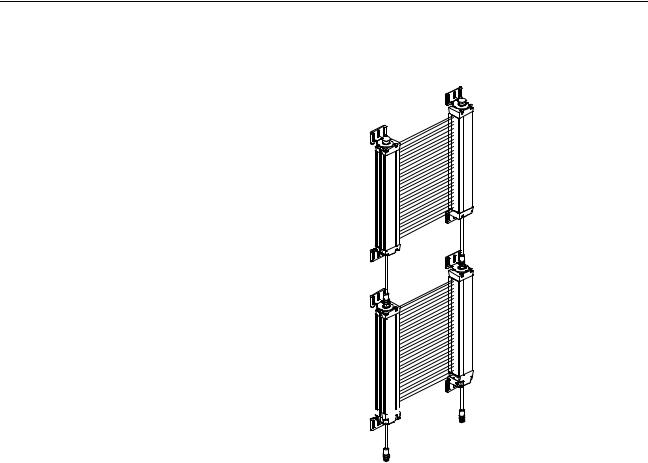
4-3 MS4800FS Cascaded Series
The MS4800 series safety light curtain is available in a "cascaded" version, referred to as the MS4800FS series. The MS4800FS series allows multiple transmitters/receivers to be "daisy-chained" in series. This type of arrangement permits the MS4800FS to guard multiple areas of a machine.
4-3-1 MS4800FS Requirements
The MS4800FS is offered in protective heights ranging from 280 mm to 1800 mm for 14 mm resolution and 280 mm to 2120 mm for 30 mm resolution.
•An MS4800FS system has a maximum size limitation based on the number of beams. A master (first) segment cannot exceed 180 beams and the total of the combined segments cannot exceed 256 beams.
•A cascaded slave segment cannot exceed 128 beams.
•An MS4800FS system may have up to four daisy-chained segments. As long as the total number of beams does not exceed 256.
•The interconnect cable length limitation between any two segments is in total max.10 meter for transmitter and receiver.
6
MS4800FS Cascaded Series |
Section 4-3 |
•It is possible to mix segments with different resolutions within an MS4800FS system.
"Cascaded" Segment (Slave)
Receiver
Segment
(Master) 


"Cascaded" Segment (Slave)
Transmitter Segment (Master)
4-3-2 MS4800FS Segment Reduction Restart Procedure
!WARNING Do not remove cascaded segments from your installation without making sure that the accessible areas are protected by other measures. Failure to do so may result in serious injury.
When you reduce the number of cascaded segments you cause a flex bus fault. The MS4800FS will enter a fault condition, indicated by error code "95" on the indicators in the bottom part of the device. This fault code indicates that there was a reduction in the number of cascaded segments. If the number of segments is reduced while power is off, the light curtain will power on with fault code "100".
There is one possibility to clear this fault and restore operation on the reduced size MS4800FS. The start switch needs to be pressed while the power is applied. The three indicator LEDs (red, yellow, amber) will flash for approximately three seconds. The start switch must be released while the LEDs are flashing to clear fault code "100". Since the MS4800FS has a configurable start input, care must be taken to ensure that the correct contact configuration is used and that it is wired properly.
The transmitter will not fault if the number of segments is reduced. However, to operate normally the transmitter must always match the receiver in the number of segments and beams.
7

MS4800FS Cascaded Series |
Section 4-3 |
8
SECTION 5
Detection Options
!WARNING Use of Fixed Blanking and Floating Blanking will make an MS4800 system less sensitive to objects in the detection zone. Improper use of these features can result in severe injury to personnel. Fixed Blanking may require a hard barrier guard. Fixed Blanking and Floating Blanking may require an increase in the safety distance. Read the following section carefully.
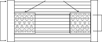
5-1 Fixed Blanking
|
Additional Hard Guarding |
|
Zone |
|
Fixed |
Detection |
Obstruction |
Blanking |
|
|
Area |
Light Curtain |
|
Light Curtain |
Fixed Blanking allows a system to blank optical beams and record the exact pattern. A system can record and store a single pattern. The protected zone's object detection is then based on the stored pattern. All obstructed optical beams recorded during the selection must remain blocked and all clear beams recorded during the selection must remain clear for the system to enter or remain in the MACHINE RUN state.
A Fixed Blanking pattern may consist of more than one Fixed Blanked area. Individual Fixed Blanked areas must be separated by at least one beam that is always clear. A Fixed Blanking area may not crossover between "flexible" segment boundaries.
Each Fixed Blanked area has a size and positional tolerance of ±1 beam to allow for slight position variance and only the two beams on the edges of the blanked area are allowed to vary. Because of this position tolerance, a reduction of the optical resolution takes place on the border area of Fixed Blanking patterns. This reduction comprises two beams.
Tolerance effect of Fixed Blanked area on Resolution
Standard Resolution |
Effective Resolution at Ends of Fixed Blanked Areas |
|
|
14 mm |
34 mm |
|
|
30 mm |
60 mm |
|
|
Note The tolerance does not reduce the resolution of the entire light curtain, only the ends of Fixed Blanked Areas. The user must consider the increased resolution of the two beams at the ends of each Fixed Blanked Area.
9
Fixed Blanking Section 5-1
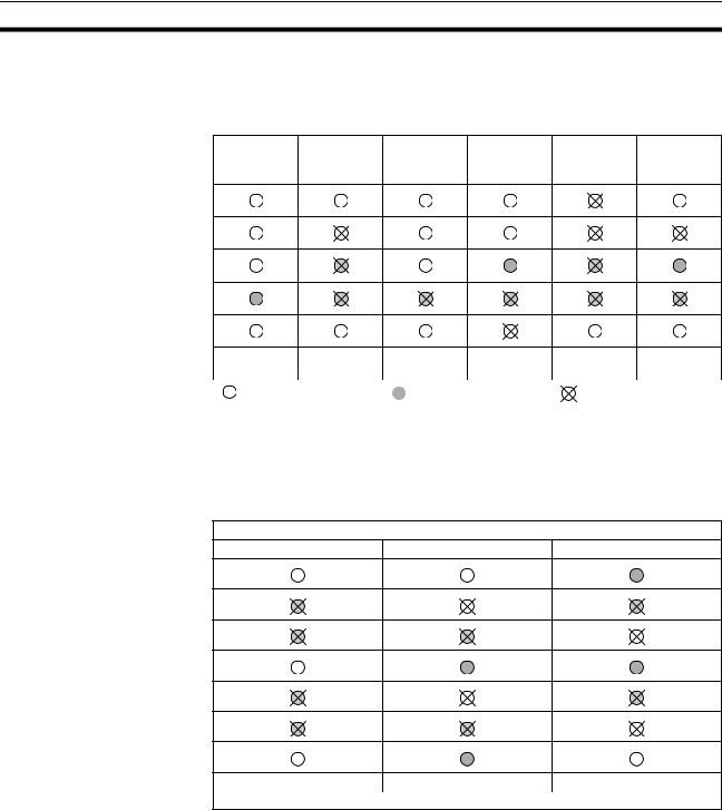
The effect of this tolerance also allows the number of blocked beams to vary ±1. For example, a Fixed Blanked area of 8 blanked beams is allowed to increase to 9 beams or decrease to 7 beams and the light curtain will remain in MACHINE RUN.
|
Fixed |
Fixed |
Fixed |
Fixed |
Fixed |
No Fixed |
Blanking |
Blanking |
Blanking |
Blanking |
Blanking |
Blanking |
Enabled |
Enabled |
Enabled |
Enabled |
Enabled |
MACHINE |
MACHINE |
MACHINE |
MACHINE |
MACHINE |
MACHINE |
|
STOP |
RUN |
|
RUN |
RUN |
STOP |
STOP |
|
|
|
|
|||
Clear Optical |
|
Blocked Optical Chan- |
Optical Channel |
|||
|
||||||
Channel |
|
|
nel |
|
Selected by Fixed |
|
|
|
|
||||
|
|
|
|
|
Blanking |
|
There is an exception when there is only one clear beam separating Fixed Blanked areas. For only this case, there is no positional tolerance allowed on that side of the clear beam for the object closest to the entry endcap so that clear beam can only be used by the object further away from the entry endcap. See the following table:
Opposite to entry endcap end
Fixed blanking enabled |
Fixed blanking enabled |
Fixed blanking enabled |
MACHINE RUN |
MACHINE RUN |
MACHINE STOP |
|
Entry endcap end |
|
The minimum number of beams in a Fixed Blanking area is one. If only one beam is blanked, the number of blocked beams has a size tolerance of +1/-0 meaning the number of blocked beams can increase to two but the area cannot be completely eliminated.
The Fixed Blanking pattern must not prevent the light curtain from synchronizing. This means that the size of the blanked object can not exceed certain limits as long as synchronization is maintained.
Fixed Blanking is allowed during all modes of operation (automatic start, start and start/restart interlock).
10

Fixed Blanking |
Section 5-1 |
5-1-1 Selecting Fixed Blanking with selector switches
To use Fixed Blanking, the operator enables the option using the selector switches. A new Fixed Blanking pattern is recorded when the MS4800 receiver is in MACHINE STOP, the blanking function is active and the Program function is activated. If the Fixed Blanking feature is disabled, the stored protected zone patterns are cleared.
1. The obstruction is placed within the detection zone and the receiver goes to
MACHINE STOP state. An authorized user then sets the selector switches in the receiver endcap to
select Fixed Blanking En-
able. The MS4800 enters a fault state and power is
cycled or the Start switch is activated to clear the fault. When the receiver powers up it will be in Fixed Blanking mode with the red and amber LEDs lit.
2. The authorized user then |
|
|
|
|
|
|
|
|
|
|
|
|
|
|
off |
|
|
|
|
|
|
|
|
|
|
|
|
|
||||||||||||
|
|
|
|
|
|
|
|
|
|
|
|
|
|
|
|
|
|
|
|
|
|
|
|
|
||||||||||||||||
enables |
the |
Program |
|
|
1 |
2 |
|
3 |
|
4 |
|
5 |
|
|
|
|
6 |
|
|
ON |
SWA |
IBIs of blocked |
|
|
|
|
|
|||||||||||||
|
|
|
|
|
|
|
|
|
|
|
|
|
|
|
|
|||||||||||||||||||||||||
switch |
by |
setting |
both |
|
|
|
|
|
|
|
|
|
|
|
|
|
|
|
|
|
||||||||||||||||||||
|
|
|
|
|
|
|
|
|
|
|
|
|
|
|
|
|
|
|
|
|
|
|
|
SWB |
beams flash. |
|
|
|
|
|
||||||||||
|
|
1 |
2 |
|
3 |
|
4 |
|
5 |
|
|
|
|
|
6 |
|
|
ON |
|
|
|
|
|
|||||||||||||||||
Fixed Blanking switches to |
|
|
|
|
|
|
|
|
|
|
|
|
|
|
|
|
|
|
|
|
||||||||||||||||||||
|
|
|
|
|
|
|
|
|
|
|
|
|
|
|
|
|
|
|
||||||||||||||||||||||
|
|
|
|
|
|
|
|
|
|
|
|
|
|
off |
|
|
|
|
|
|
|
|
|
|
|
|
|
|||||||||||||
the off position and then |
|
|
|
|
|
|
|
|
|
|
|
|
|
|
|
|
|
|
|
|
|
|
|
|
|
|
|
|||||||||||||
|
|
|
|
|
|
|
|
|
|
|
|
|
|
|
on |
|
|
|
|
|
|
|
|
|
|
|
|
|
||||||||||||
both |
to |
the |
on |
position. |
1 |
2 |
|
3 |
|
4 |
|
5 |
|
|
|
|
|
6 |
|
|
ON |
|
|
|
|
|
|
|
|
|
|
|||||||||
|
|
|
|
|
|
|
|
|
|
|
|
|
|
|
|
|
|
|
|
|||||||||||||||||||||
When |
the |
first |
Fixed |
|
|
|
|
|
|
|
|
|
|
|
|
|
|
|
|
|
|
|
|
|
|
|
|
|
|
|
|
|
|
|
|
|
|
|||
|
|
1 |
|
2 |
|
|
3 |
|
|
4 |
|
|
5 |
|
|
|
|
|
6 |
|
|
ON |
|
|
|
|
|
|
|
|
|
|
||||||||
Blanking switch is flipped, |
|
|
|
|
|
|
|
|
|
|
|
|
|
|
|
|
|
|
|
|
|
|
|
|
|
|
||||||||||||||
|
|
|
|
|
|
|
|
|
|
|
|
|
|
|
on |
|
|
|
|
|
|
|
|
|
|
|
|
|
||||||||||||
the red LED begins flash- |
|
|
|
|
|
|
|
|
|
|
|
|
|
|
|
|
|
|
|
|
|
|
Red and amber LEDs and IBIs |
|
|
|
|
|
|
|||||||||||
|
|
|
|
|
|
|
|
|
|
|
|
|
|
|
|
|
|
|
|
|
|
|
||||||||||||||||||
ing at a rate of 3Hz. When |
|
|
|
|
|
|
|
|
|
|
|
|
|
|
|
|
|
|
|
|
|
|
|
|
|
flash to indicate the |
||||||||||||||
|
|
|
|
|
|
|
|
|
|
|
|
|
|
|
|
|
|
|
|
|
|
|
|
Program switch is active. |
||||||||||||||||
the final Fixed |
Blanking |
|
|
|
|
|
|
|
|
|
|
|
|
|
|
|
|
|
|
|
|
|
|
|
|
|||||||||||||||
|
|
|
|
|
|
|
|
|
|
|
|
|
|
|
|
|
|
|
|
|
|
|
|
|
|
|
|
|
|
|
|
|
|
|||||||
switch is flipped, both the red and amber LEDs and the IBIs (Individual |
||||||||||||||||||||||||||||||||||||||||
Beam Indicators) of the blocked beams start flashing to indicate the Pro- |
||||||||||||||||||||||||||||||||||||||||
gram switch is enabled. The authorized user has 10 minutes to complete |
||||||||||||||||||||||||||||||||||||||||
the programming of a pattern. |
|
|
|
|
|
|
|
|
|
|
|
|
|
|
|
|
|
|
|
|
|
|
|
|
|
|
|
|
|
|
||||||||||
3. To program a pattern, the |
|
|
|
|
|
|
|
|
|
|
|
|
|
|
on |
|
|
|
Flip |
|
|
|
|
|
|
|
|
|
|
|||||||||||
authorized user must flip |
|
|
|
|
|
|
|
|
|
|
|
|
|
|
|
|
|
|
|
|
|
|
|
|
|
|
|
|
|
|
|
|
|
|
||||||
|
1 |
|
2 |
3 |
4 |
5 |
|
|
|
6 |
|
ON |
SWA |
IBIs of blocked |
|
|
|
|||||||||||||||||||||||
(off/on or on/off) the Pro- |
|
|
|
|
|
|
|
|
|
|
|
|
|
|
|
|
|
|
|
|
|
|
|
|
|
SWB |
beams flash. |
|
|
|
||||||||||
|
1 |
|
2 |
|
3 |
|
4 |
|
5 |
|
|
|
6 |
|
|
|
|
|
|
|||||||||||||||||||||
gram |
switch |
once. Once |
|
|
|
|
|
|
|
|
|
ON |
|
|
|
|
|
|
|
|
|
|||||||||||||||||||
|
|
|
|
|
|
|
|
|
|
|
|
|
|
|
on |
|
|
|
|
|
|
|
|
|
|
|
|
|
||||||||||||
pattern is programmed the |
|
|
|
|
|
|
|
|
|
|
|
|
|
|
|
|
|
|
|
|
|
|
|
|
|
|
|
|||||||||||||
|
|
|
|
|
|
|
|
|
|
|
|
|
|
|
|
|
|
|
|
|
|
|
|
|
|
|
|
|
|
|
|
|
|
|||||||
yellow LED (INTERLOCK) |
|
|
|
|
|
|
|
|
|
|
|
|
|
|
|
|
|
|
|
|
|
|
|
|
|
|
|
|
|
|
|
|
|
|
||||||
turns |
|
on. |
During 10 |
|
|
|
|
|
|
|
|
|
|
|
|
|
|
|
|
|
|
|
|
|
|
|
|
|
|
|
|
|
|
|
|
|
|
|||
minute |
period, |
the |
user |
|
|
|
|
|
|
|
|
|
|
|
|
|
|
|
|
|
|
|
|
|
|
|
|
|
|
|
|
|
|
|
|
|
|
|||
may |
program |
as |
many |
|
|
|
|
|
|
|
|
|
|
|
|
|
|
|
|
|
|
|
|
|
Yellow LED turns on to indicate |
|||||||||||||||
times as needed, allowing |
|
|
|
|
|
|
|
|
|
|
|
|
|
|
|
|
|
|
|
|
the pattern has been programmed |
|||||||||||||||||||
|
|
|
|
|
|
|
|
|
|
|
|
|
|
|
|
|
|
|
|
|
|
|
and the Start button is active. |
|
|
|
|
|
|
|
|
|||||||||
for |
adjustment |
in |
the |
|
|
|
|
|
|
|
|
|
|
|
|
|
|
|
|
|
|
|
|
|
|
|
|
|
||||||||||||
|
|
|
|
|
|
|
|
|
|
|
|
|
|
|
|
|
|
|
|
|
|
|
|
|
|
|
|
|
|
|
|
|
|
|||||||
placement of the obstruction.
11

Fixed Blanking |
|
|
|
|
|
|
|
|
|
|
|
|
|
|
|
|
|
|
|
|
|
|
|
Section 5-1 |
|||||
4. The user must then press |
|
|
|
|
|
|
|
|
|
|
|
|
|
|
|
|
|
|
|
|
|
|
|
|
|
|
|||
|
|
|
|
|
|
|
|
|
|
|
|
|
|
|
|
|
|
|
|
|
|
|
|
|
|
||||
and release the Start but- |
|
|
|
|
|
|
|
|
|
|
|
|
|
|
|
|
|
|
|
|
IBIs of blocked |
|
|
|
|
||||
ton or perform a power cy- |
|
|
|
|
|
|
|
|
|
|
|
|
|
|
|
|
|
|
|
|
beams off. |
|
|
|
|
||||
|
|
|
|
|
|
|
|
|
|
|
|
|
|
|
|
|
|
|
|
|
|
|
|
|
|
||||
cle. The MS4800 receiver |
|
|
|
|
|
|
|
|
|
|
|
|
on |
|
|
|
|
|
|
|
|
|
|||||||
|
|
|
|
|
|
|
|
|
|
|
|
|
|
|
|
|
|
|
|
|
|||||||||
then resets. If no faults are |
|
|
|
|
|
|
|
|
|
|
|
|
|
|
|
|
|
|
|
|
|
||||||||
|
|
|
|
|
|
|
|
|
|
|
|
|
|
|
|
|
|
|
|
SWA |
|
|
|||||||
1 |
|
2 |
|
3 |
|
4 |
|
5 |
|
|
6 |
|
|
ON |
|
|
|||||||||||||
detected and the state of |
|
|
|
|
|
|
|
|
|
|
|
||||||||||||||||||
|
|
|
|
|
|
|
|
|
|
|
|
||||||||||||||||||
|
|
|
|
|
|
|
|
|
|
|
|
|
|
|
|
|
|
|
|
|
SWB |
|
|
||||||
|
|
|
|
|
|
|
|
|
|
|
|
|
|
|
|
|
|
|
|
|
|
|
|||||||
the optical beams match- |
|
1 |
|
|
2 |
|
|
3 |
|
|
4 |
|
|
5 |
|
|
|
6 |
|
|
ON |
|
|
||||||
|
|
|
|
|
|
|
|
|
|
|
|
|
|
|
|
||||||||||||||
|
|
|
|
|
|
|
|
|
|
|
|
|
|
on |
|
|
|
|
|
||||||||||
es the |
recorded |
Fixed |
|
|
|
|
|
|
|
|
|
|
|
|
|
|
|
|
|
|
|
|
|
|
|||||
|
|
|
|
|
|
|
|
|
|
|
|
Amber LED is on to indicate |
|
|
|
|
|
||||||||||||
Blanking |
pattern, |
the re- |
|
|
|
|
|
|
|
|
|
|
|
|
|
|
|||||||||||||
|
|
|
|
|
|
|
|
|
|
|
|||||||||||||||||||
|
|
|
|
|
|
|
|
|
|
|
|
|
|
|
|
|
in Fixed Blanking mode. |
||||||||||||
|
|
|
|
|
|
|
|
|
|
|
|
|
|
|
|
|
|
|
|
|
|||||||||
ceiver will enter the IN-
TERLOCK or MACHINE RUN condition depending upon the selected Start Mode. The amber receiver Blanking Active LED will be on.
5. If the 10 minutes period |
|
|
|
|
|
|
|
|
|
|
|
|
|
|
|
|||||
expires, the |
amber LED |
|
|
|
|
|
|
|
|
|
|
|
|
|
|
IBIs of blocked |
||||
and IBIs (Individual Beam |
|
|
|
|
|
|
|
|
|
|
|
|
|
|
beams on. |
|||||
|
|
|
|
|
|
|
|
|
|
|
|
|
|
|
||||||
Indicators) |
quit |
flashing |
|
|
|
|
|
|
|
|
on |
|
|
|||||||
and the yellow LED (IN- |
|
|
|
|
|
|
|
|
|
|
|
|
|
|
SWA |
|||||
1 |
|
2 |
|
3 |
|
4 |
|
5 |
|
6 |
|
|
ON |
|||||||
TERLOCK) goes on. The |
|
|
|
|
|
|
|
|
||||||||||||
|
|
|
|
|
|
|
|
|
|
|
|
|
|
|
SWB |
|||||
|
|
|
|
|
|
|
|
|
|
|
|
|
|
|
||||||
user |
can |
start |
another |
|
1 |
|
2 |
|
3 |
|
4 |
|
5 |
|
6 |
|
|
ON |
||
|
|
|
|
|
|
|
|
|
|
on |
|
|||||||||
programming |
sequence |
|
|
|
|
|
|
|
|
|
|
|
||||||||
|
|
|
|
|
|
|
|
|
|
|
|
|
|
|
||||||
by |
setting |
|
both |
Fixed |
|
|
|
|
|
|
|
|
|
Amber LED is off to indicate |
||||||
|
|
|
|
|
|
|
|
|
|
|
|
|
|
|
||||||
Blanking switches off and then on. The user may
start normal operation by a press and release of the start button or by performing a power cycle.
6.To exit Fixed Blanking the user sets both selector switches to the off position, then either presses and releases the Start button or performs a power cycle. The receiver will power up with the amber LED off.
IBIs of blocked
beams on.
off
1
 2
2 
 3
3 
 4
4 
 5
5
 6
6  ON SWA
1
 2
2 
 3
3 
 4
4 
 5
5 
 6
6 
 ON SWB
off
The amber LED and IBIs quit flashing to indicate program switch is disabled. The yellow LED turns on to indicate the Start button is active.
Note Please refer for further information to the FAQ to section 17-6.
12
Loading...