


 Loading...
Solid-State Timer |
|
H3DR |
|
|
|
|
|
|
Analog Set Multifunction Timers in
Slim Design for Track Mounting
■All settings are made though front panel
■Six operating modes in a single timer provides flexibility for many applications
■Economical ON-delay only models available in six, single-time ranges
■Wide timing range of 0.12 seconds to 120 hours
■Fine adjustment dial for precise time setting
■Name plates provide for easy timer identification and management
■Terminal block accepts both fork or bar-sleeve connectors
Ordering Information
■ MULTIFUNCTION TIMERS
Timing functions |
ON-delay, Repeat cycle/signal OFF start, Repeat cycle/signal ON start, |
|||
|
|
Signal ON/OFF-delay, Signal OFF-delay, and Interval |
|
|
|
|
|
|
|
Terminal form |
Screw terminals |
|
|
|
Outputs |
|
DPDT contact |
SPDT contact |
NPN/PNP transistor |
Part |
AC supply voltage |
H3DR-A-AC100-240 |
H3DR-P-AC100-120 |
— |
number |
(50/60 Hz) |
|
H3DR-P-AC200-240 |
|
|
|
|
|
|
|
AC/DC supply voltage |
H3DR-A-AC/DC24 |
H3DR-P-AC/DC24 |
H3DR-AS-AC/DC24 |
|
|
|
|
|
|
DC supply voltage |
H3DR-A-DC12 |
— |
H3DR-AS-DC12 |
|
|
|
|
|
■ ON-DELAY ONLY TIMERS
Timing ranges |
1S = 0.1 to 1 second; 5S = 0.2 to 5 seconds; 10S = 0.5 to 10 seconds; |
||
|
30S = 1 to 30 seconds; 60S = 2 to 60 seconds; 10M = 0.5 to 10 minutes |
||
|
|
|
|
Terminal form |
Screw terminals |
|
|
|
|
|
|
Output |
SPDT contact |
|
|
|
|
|
|
Supply voltage |
110 to 120 VAC, 50/60 Hz |
220 to 240 VAC, 50/60 Hz |
24 VAC/VDC |
|
|
|
|
Part number |
H3DR-M-AC110-120-1S |
H3DR-M-AC220-240-1S |
H3DR-M-AC/DC24-1S |
|
H3DR-M-AC110-120-5S |
H3DR-M-AC220-240-5S |
H3DR-M-AC/DC24-5S |
|
H3DR-M-AC110-120-10S |
H3DR-M-AC220-240-10S |
H3DR-M-AC/DC24-10S |
|
H3DR-M-AC110-120-30S |
H3DR-M-AC220-240-30S |
H3DR-M-AC/DC24-30S |
|
H3DR-M-AC110-120-60S |
H3DR-M-AC220-240-60S |
H3DR-M-AC/DC24-60S |
|
H3DR-M-AC110-120-10M |
H3DR-M-AC220-240-10M |
H3DR-M-AC/DC24-10M |
|
|
|
|
■ ACCESSORIES
Description |
|
Part number |
Mounting track |
DIN rail, 50 cm (1.64 ft) length |
PFP-50N |
|
|
|
|
DIN rail, 1 m (3.28 ft) length |
PFP-100N |
|
End plate |
PFP-M |
|
Spacer |
PFP-S |
|
|
|
1
H3DR
■ RANGE SELECTION
H3DR-A, H3DR-AS
Scale range |
Time unit |
display |
display |
Power ON indicator
Time setting knob
Operation mode selector
Mode display
A:ON-delay
B:Repeat cycle, signal OFF start B2: Repeat cycle, signal ON start
C:Signal ON/OFF-delay
D:Signal OFF-delay
E:Interval
H3DR
Timing unit |
Seconds |
Minutes |
Hours |
10 hours |
|
|
|
|
|
|
|
Setting |
0 |
Instantaneous output |
|
||
|
|
|
|
|
|
Time |
x 0.1 |
0.12 to 1.2 |
1.2 to 12 |
||
|
|
|
|
||
scale |
x 1 |
1.2 to 12 |
12 to 120 |
||
Identification panel for user notation
Time unit selector: sec, min, hr, 10h
Output indicator
Fine-tuning adjustment
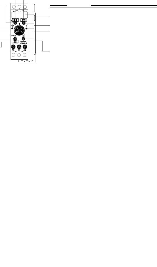
H3DR-P
Scale range |
Time unit |
display |
display |
Scale range selector
Power ON indicator
Time setting knob
Operation mode selector
Mode display
A:ON-delay
B:Repeat cycle, signal OFF start B2: Repeat cycle, signal ON start
C:Signal ON/OFF-delay
D:Signal OFF-delay
E:Interval
Identification panel for user notation
Time unit selector: sec, min, hr, 10h
Output indicator
Fine-tuning adjustment
H3DR-M
Identification panel for user notation
Power ON indicator
Time setting knob
Timing unit |
Seconds |
Minutes |
Hours |
10 hours |
|
Setting |
0 |
Instantaneous output |
|
||
Time |
x 0.1 |
0.12 to 1.2 |
1.2 to 12 |
||
|
|
|
|
|
|
scale |
x 1 |
1.2 to 12 |
12 to 120 |
||
|
|
|
|
|
|
Rated time |
Time range |
1 s |
0.1 to 1 second |
5 s |
0.2 to 5 seconds |
10 s |
0.5 to 10 seconds |
30 s |
1 to 30 seconds |
60 s |
2 to 60 seconds |
10 min |
0.5 to 10 minutes |
2

H3DR 

 H3DR
H3DR
Specifications
Part number |
|
H3DR-A |
H3DR-AS |
|
H3DR-P |
H3DR-M |
|||
Supply voltage |
AC |
24 V or 100-240, 50/60 Hz |
|
24 V, 100-120 V or |
24 V, 110-120 V or |
||||
|
|
|
|
|
|
|
|
200-240 V, 50/60 Hz |
220-240 VAC, 50/60 Hz |
|
|
|
|
DC |
12 V or 24 V |
|
|
24 V |
24 V |
Operating voltage |
|
85% to 110% of rated voltage (90% to 110% with 12 VDC type) |
|
||||||
Power |
|
|
AC |
10 VA |
|
|
6 VA, 100-120 VAC |
6 VA, 110-120 VAC |
|
consumption |
|
|
|
|
10 VA, 200-240 VAC |
10 VA, 220-240 VAC |
|||
|
|
|
|
|
|
|
|
2 VA, 24 VAC |
2 VA, 24 VAC |
|
|
|
|
DC |
1 W |
|
|
1 W, 24 VDC |
1 W, 24 VDC |
Timing |
|
|
|
ON-delay, Repeat cycle/signal OFF start, Repeat cycle/signal |
ON-delay |
||||
functions |
|
|
|
ON start, Signal ON/OFF-delay, Signal OFF-delay, and Interval |
|
||||
Start, reset, |
|
Type |
No-voltage input |
|
|
|
— |
||
gate inputs* |
ON impedance |
1 kΩ max. |
|
|
|
|
|||
|
|
|
|
Residual voltage |
1 V max. |
|
|
|
|
|
|
|
|
OFF impedance |
100 kΩ min. |
|
|
|
|
Control |
|
Type |
Time limit |
DPDT contact |
NPN or PNP** |
|
SPDT contact |
SPDT contact |
|
output |
|
|
|
|
|
transistor |
|
|
|
|
|
|
|
Instantaneous |
— |
— |
|
— |
— |
|
|
Max. load |
|
5 A, 250 VAC |
100 mA, 30 VDC |
|
5 A, 250 VAC |
5 A, 250 VAC |
|
|
|
|
|
|
(p.f. = 1) |
max. with 2 VDC |
|
(p.f. = 1) |
(p.f. = 1) |
|
|
|
|
|
|
residual voltage |
|
|
|
|
|
Min. load |
|
100 mA, 5 VDC |
— |
|
100 mA, 5 VDC |
100 mA, 5 VDC |
|
Repeat accuracy |
|
±1% FS max. (1% ±10 ms in the 1.2 s range) |
±2% FS max. |
||||||
Setting error |
|
±10% FS ±0.05 s max. |
|
|
|
||||
Resetting system |
|
Power reset with minimum power opening time of 0.1 s |
|
||||||
Resetting time |
|
0.1 s max. |
|
|
|
|
|||
Indicators |
|
|
|
Power (green LED), Output ON (orange LED) |
Power (green LED) |
||||
Materials |
|
|
|
Plastic case, knob |
|
|
|
|
|
Mounting |
|
|
|
DIN rail track |
|
|
|
|
|
Connections |
|
Terminal screws |
|
|
|
|
|||
Weight |
|
|
|
120 g (4.7 oz.) |
|
|
|
|
|
Approvals |
|
|
|
UL/CSA/CE (EMC) (LV) |
|
|
|
||
|
|
|
|
|
|
||||
Operating ambient temperature |
-10° to 55°C (14° to 131°F) |
|
|
|
|||||
Humidity |
|
|
|
35 to 85% RH |
|
|
|
|
|
Vibration |
|
Mechanical durability |
10 to 55 Hz, 1.5 mm (0.06 in) double |
|
10 to 55 Hz with 0.75 mm (0.03 in) double |
||||
|
|
|
|
|
amplitude each in three directions |
|
amplitude each in three directions |
||
|
|
|
|
|
|
||||
|
|
Malfunction durability |
10 to 55 Hz, 0.5 mm (0.02 in) double |
|
10 to 55 Hz with 0.5 mm (0.02 in) double |
||||
|
|
|
|
|
amplitude each in three directions |
|
amplitude each in three directions |
||
Shock |
|
Mechanical durability |
30 G each in three directions |
|
100 G each in three directions |
||||
|
|
Malfunction durability |
10 G each in three directions |
|
10 G each in three directions |
||||
Variation due to voltage change |
±0.5% FS max., ±0.5% ±10 ms max. in |
|
the 1.2 s range |
±2% FS max. |
|||||
Variation due to temperature change |
±2% FS max., ±0.2% ±10 ms max. in the 1.2 s range |
±5% FS max. |
|||||||
Insulation resistance |
|
100 MΩ min. at 500 VDC |
|
|
|
||||
Dielectric strength |
|
2,000 VAC, 50/60 Hz for 1 minute between current-carrying and non-current-carrying parts |
|||||||
|
|
|
|
|
2,000 VAC, 50/60 Hz for 1 minute between control output terminals and operating circuit |
||||
|
|
|
|
|
1,000 VAC, 50/60 Hz for 1 minute between contacts not located next to each other |
||||
Service life |
Mechanical |
20 million operations minimum at 1,800 operations/hour |
|
||||||
|
|
|
|
Electrical |
100,000 operations minimum at 5 A, 250 VAC (p.f. = 1) |
|
|||
NOTE:
*H3DR-P has start input only; H3DR-M has no inputs.
**The internal circuits are optically isolated from the output, enabling application of either NPN or PNP transistor devices.
3

H3DR
Engineering Data
■ ELECTRICAL SERVICE LIFE
(thousands) |
10,000 |
|
5,000 |
||
|
||
operations |
500 |
|
|
1,000 |
|
|
30 VDC L/R = 7 ms |
|
||
Electrical |
|
|
|
250 VAC/30 VDC |
|
|
|
|
(p.f. = 1) |
|
|
|
|
|
|
|
|
100 |
|
|
|
|
|
|
250 VAC (p.f. = 0.4) |
|
|
||
0 |
1 |
2 |
3 |
4 |
5 |
|
|
Load current (A) |
|
||
H3DR
Reference:
A maximum current of 0.15 A can be switched at 125 VDC (p.f. = 1). Maximum current of 0.1 A can be switched if L/R is 7 ms. In both cases, a life of 100,000 operations can be expected.
The minimum applicable load is 10 mA at 5 VDC.
Timing Charts
■ H3DR-M ON-DELAY ONLY TIMER
Note: |
The minimum reset time is 0.1 s and the minimum signal input delay is 0.05 s. |
||
|
The letter "t" in the timing charts stands for the set time and "t–a" means that the period is less than the time set. |
||
|
|
|
|
Output mode |
|
Timing chart |
|
|
|
|
|
A: ON-delay |
|
|
|
|
|
Power |
ON |
|
|
(A1 and A2) |
OFF |
|
|
Output relay |
ON |
|
|
(NC, 15 and 16) |
OFF |
|
|
Output relay |
ON |
|
|
(NO, 15 and 18) |
OFF |
|
|
Power indicator |
ON |
|
|
|
OFF |
|
|
|
|
■ H3DR-P MULTI-MODE TIMER WITH POWER-OFF RESET
Output mode |
|
|
|
Timing chart |
|
|
|
|
|
|
|
A: ON-delay |
|
|
|
|
|
Short-circuit start |
Power |
ON |
|||
input C1 and A2. |
|||||
(A |
1 |
and A ) |
OFF |
||
|
|
2 |
|
||
|
Start |
ON |
|||
|
(C1 and A2) |
OFF |
|||
|
Output relay |
ON |
|||
|
(NC, 15 and 16) |
OFF |
|||
|
Output relay |
ON |
|||
|
(NO, 15 and 18) |
OFF |
|||
|
output indicator |
|
|||
|
Power indicator |
ON |
|||
|
|
|
|
OFF |
|
|
|
|
|
|
|
4
Loading...