


Multifunction Counter/Tachometer
H7CX Series
Please read and understand this catalog before purchasing the products. Please consult your OMRON representative if you have any questions or comments. Refer to Warranty and Application Considerations (page 64), and Safety Precautions (page 59).
DIN 48 × 48 mm Multifunction Counter/Tachometer Series
•Highly visible display with backlit negative transmissive LCD.
•Intuitive setting enabled using ergonomic up/down digit keys (4-digit models) and DIP switch.
•PNP/NPN switchable DC voltage input.
•Finger-safe terminals (screw terminal block models).
•Complies with IP66/NEMA4/UL Type 4X (when using the Y92S-29 Waterproof Packing and Y92F-30 Flush Mounting Adapter).
H7CX Series
H7CX-A |
|
H7CX-R |
|
|
|
Multifunction Counter |
Tachometer |
Preset Counter |
|
Total Counter |
|
Batch Counter |
|
Dual Counter |
|
Tachometer |
|
Contents |
|
Multifunction Counter |
|
H7CX-A............................................................ |
2 |
Tachometer |
|
H7CX-R............................................................ |
42 |
Common to All Models |
|
Safety Precautions ........................................... |
59 |
Warranty and Application Consideration.......... |
64 |
Multifunction Counter/Tachometer H7CX Series |
1 |
Multifunction Preset Counter |
|
H7CX-A |
|
DIN 48 × 48 mm Multifunction Preset Counter |
|
with a Bright, Easy-to-view, Negative |
|
Transmissive LCD |
|
• Programmable PV color to visually alert when output status |
|
changes (screw terminal block models). |
|
• Configurable as 1-stage counter, 2-stage counter, total and pre- |
|
set counter, batch counter, dual counter, or tachometer. (Config- |
|
urability varies with model.) |
|
• Meets a variety of mounting requirements: |
|
Screw terminal block models, and pin-style terminal models. |
|
• Six-language instruction manual. |
|
Contents |
|
Model Number Structure .............................................................. |
3 |
Ordering Information .................................................................... |
3 |
Specifications ............................................................................... |
4 |
Connections ................................................................................. |
8 |
Nomenclature ............................................................................... |
12 |
Dimensions................................................................................... |
13 |
Operating Procedures .................................................................. |
17 |
Setting Procedure Guide........................................................ |
17 |
Operating Procedures (Counter Function) ............................. |
18 |
Operating Procedures (Tachometer Function) ....................... |
30 |
Operation in Configuration Selection Mode ........................... |
36 |
Additional Information................................................................... |
37 |
2 |
Multifunction Preset Counter H7CX-A |

Model Number Structure
■ Model Number Legend
H7CX-A@@@@@@
1 |
2 |
3 |
4 |
5 |
6 |
1.External connection
None: Screw terminals
11:11-pin socket
2.No. of digits
None: 6 digits
4:4 digits
3.Stage setting
None: 1-stage setting
U:Factory-set to 1-stage setting
W:Factory-set to 2-stage setting
4.Output type
None: Contact output or contact and transistor in combination
S:Transistor output
5.Supply voltage/external power supply
None: 100 to 240 VAC at 50/60 Hz with 12 VDC power supply
D:12 to 24 VDC without external power supply
D1: 12 to 24 VDC or 24 VAC at 50/60 Hz with 12 VDC power supply
6.Case color
None: Black
G:Light gray (Munsell 5Y7/1): Produced upon request.
Ordering Information
■ List of Models
Supported configurations |
|
• 1-stage counter |
|
|
|
• 1-stage counter |
|
• 1-stage counter |
|||||
|
|
|
|
• 1-stage counter with total counter |
|
|
• |
2-stage counter |
|
• |
2-stage counter |
||
|
|
|
|
|
|
|
|
• |
1-stage counter with total |
|
• |
1-stage counter |
|
|
|
|
|
|
|
|
|
• |
counter |
|
|
• |
with total counter |
|
|
|
|
|
|
|
|
1-stage counter with batch |
|
1-stage counter |
|||
|
|
|
|
|
|
|
|
• |
counter |
|
|
• |
with batch counter |
|
|
|
|
|
|
|
|
Dual counter (addition/subtrac- |
|
Dual counter (addi- |
|||
|
|
|
|
|
|
|
|
• |
tion) |
|
|
|
tion only) |
|
|
|
|
|
|
|
|
Tachometer |
|
|
|
|
|
Sensor |
Output type |
Supply voltage |
11-pin socket |
|
|
|
Screw terminal |
|
|
|
|||
power |
|
|
|
|
|
|
|
|
|
|
|
|
|
supply |
|
|
|
1-stage |
|
|
|
1-stage |
|
2-stage |
|||
|
|
|
|
|
|
|
(See note.) |
|
|
|
|
||
|
|
|
|
|
|
|
|
|
|
|
|
|
|
|
|
|
|
|
|
|
|
|
|
|
|
|
|
|
|
|
|
6 digits |
4 digits |
6 digits |
4 digits |
|
6 digits |
6 digits |
|
|
4 digits |
|
|
|
|
|
|
|
|
|
|
|
|
|
|
|
|
|
|
H7CX-A11@ |
H7CX-A114@ |
H7CX-A@ |
H7CX-A4@ |
|
H7CX-AU@ |
H7CX-AW@ |
|
|
H7CX-A4W@ |
12 VDC |
Contact output |
100 to 240 VAC |
H7CX-A11 |
H7CX-A114 |
H7CX-A |
H7CX-A4 |
--- |
H7CX-AW |
|
H7CX-A4W |
|||
|
|
|
|
|
|
|
|
|
|
|
|
||
|
|
|
12 to 24 VDC/ |
H7CX-A11D1 |
H7CX-A114D1 |
--- |
--- |
--- |
H7CX-AWD1 |
|
--- |
||
|
|
|
24 VAC |
|
|
|
|
|
|
|
|
|
|
|
|
Contact and |
100 to 240 VAC |
--- |
--- |
--- |
--- |
H7CX-AU |
--- |
|
--- |
||
|
|
transistor output |
|
|
|
|
|
|
|
|
|
|
|
|
|
12 to 24 VDC/ |
--- |
--- |
--- |
--- |
H7CX-AUD1 |
--- |
|
--- |
|||
|
|
|
|
||||||||||
|
|
|
24 VAC |
|
|
|
|
|
|
|
|
|
|
|
|
|
|
|
|
|
|
|
|
|
|
||
|
|
Transistor output |
100 to 240 VAC |
H7CX-A11S |
H7CX-A114S |
H7CX-AS |
H7CX-A4S |
--- |
H7CX-AWS |
|
--- |
||
|
|
|
|
|
|
|
|
|
|
|
|
||
|
|
|
12 to 24 VDC/ |
H7CX-A11SD1 |
--- |
--- |
--- |
H7CX-AUSD1 |
H7CX-AWSD1 |
|
--- |
||
|
|
|
24 VAC |
|
|
|
|
|
|
|
|
|
|
|
|
|
|
|
|
|
|
|
|
|
|||
None |
Contact output |
12 to 24 VDC |
--- |
--- |
H7CX-AD |
H7CX-A4D |
--- |
--- |
|
--- |
|||
|
|
|
|
|
|
|
|
|
|
|
|
||
|
|
Transistor output |
|
--- |
--- |
H7CX-ASD |
H7CX-A4SD |
--- |
H7CX-AWSD |
|
H7CX-A4WSD |
||
Note: Can be used as a 2-stage counter. In this case, each output can be flexibly allocated to either stage 1 or 2.
■ Accessories (Order Separately)
|
Name |
|
Models |
|
|
|
|
||
Flush Mounting Adapter (See note 1.) |
|
Y92F-30 |
||
|
|
|
|
|
Waterproof Packing (See note 1.) |
|
|
Y92S-29 |
|
|
|
|
|
|
Track Mounting/Front Connecting |
11-pin |
|
P2CF-11 |
|
Socket |
|
|
|
|
11-pin, finger-safe type |
P2CF-11-E |
|||
|
||||
|
|
|
|
|
Back Connecting Socket |
11-pin |
|
P3GA-11 |
|
|
|
|
||
|
11-pin, finger-safe type |
P3GA-11 with Y92A-48G (See note 2.) |
||
|
|
|
|
|
Hard Cover |
|
|
Y92A-48 |
|
|
|
|
|
|
Soft Cover |
|
|
Y92A-48F1 |
|
|
|
|
||
Mounting Track |
50 cm (l) × 7.3 mm (t) |
PFP-50N |
||
|
1 m (l) × |
7.3 mm (t) |
PFP-100N |
|
|
1 m (l) × |
16 mm (t) |
PFP-100N2 |
|
End Plate |
|
|
PFP-M |
|
|
|
|
|
|
Spacer |
|
|
PFP-S |
|
|
|
|
|
|
Note: 1. Supplied with screw-terminal models (i.e., excluding H7CX-A11@/-A114@ models). 2. Y92A-48G is a finger-safe terminal cover attached to the P3GA-11 Socket.
Multifunction Preset Counter H7CX-A |
3 |

Specifications
■ Ratings
Item |
|
|
H7CX-A4@ |
|
H7CX-A@ |
H7CX-A114@ |
H7CX-A11@ |
||
Classification |
|
Preset counter |
|
|
|
|
|
||
|
|
|
|
|
|||||
Supported |
|
1-stage counter, 1-stage counter with total counter (selectable) |
|
|
|||||
configurations |
|
|
|
|
|
|
|
|
|
|
|
|
|
||||||
Rated supply voltage |
100 to 240 VAC (50/60 Hz), 12 to 24 VDC |
100 to 240 VAC (50/60 Hz) |
|
||||||
(See note 1.) |
|
|
|
|
|
|
24 VAC (50/60 Hz)/12 to 24 VDC |
|
|
|
|
|
|
||||||
Operating voltage range |
85% to 110% of rated supply voltage (90% to 110% at 12 VDC) |
|
|
||||||
|
|
|
|
||||||
Power consumption |
Approx. 9.2 VA at 264 VAC |
|
|
||||||
|
|
Approx. 7.2 VA at 26.4 VAC |
|
|
|||||
|
|
Approx. 3.7 W at 12 VDC |
|
|
|||||
|
|
|
|
|
|
|
|||
Mounting method |
Flush mounting |
|
|
|
Flush mounting, surface mounting, or DIN track mounting |
||||
|
|
|
|
|
|
|
|||
External connections |
Screw terminals |
|
|
|
11-pin socket |
|
|||
|
|
|
|
|
|
|
|
||
Terminal screw |
|
0.5 N·m max. |
|
|
|
--- |
|
||
tightening torque |
|
|
|
|
|
|
|
||
Display |
|
7-segment, negative transmissive LCD |
|
|
|||||
(See note 2.) |
|
|
|
|
|
|
|
|
|
PV |
11.5-mm-high characters, red or |
9-mm-high characters, red or |
11.5-mm-high characters, red |
9-mm-high characters, red |
|||||
|
|||||||||
|
|
green (programmable) |
|
green (programmable) |
|
|
|||
|
|
|
|
|
|
||||
|
SV |
6-mm-high characters, green |
|
|
|||||
|
|
|
|
|
|
|
|||
Digits |
|
4 digits (−999 to 9,999) |
|
6 digits (−99,999 to 999,999) |
4 digits (−999 to 9,999) |
6 digits (−99,999 to 999,999) |
|||
|
|
SV range: 0 to 9,999 |
|
SV range: −99,999 to 999,999 |
SV range: 0 to 9,999 |
SV range: −99,999 to 999,999 |
|||
|
|
|
|
|
|
(See note 3.) or 0 to 999,999 |
|
(See note 3.) or 0 to 999,999 |
|
Max. counting speed |
30 Hz or 5 kHz (selectable, ON/OFF ratio 1:1), common setting for CP1 and CP2 |
|
|||||||
|
|
|
|
|
|||||
Input modes |
|
Increment, decrement, command, individual, and quadrature |
|
|
|||||
|
|
|
|
|
|||||
Input signals |
|
CP1, CP2, reset, and total reset |
|
|
|||||
|
|
|
|
|
|||||
Input method |
|
No-voltage input/voltage input (switchable) |
|
|
|||||
|
|
No-voltage input |
|
|
|
|
|
||
|
|
ON impedance: 1 kΩ max. (Leakage current: 5 to 20 mA at 0 Ω ) |
|
|
|||||
|
|
ON residual voltage: 3 V max. |
|
|
|||||
|
|
OFF impedance: 100 kΩ |
min. |
|
|
||||
|
|
Voltage input |
|
|
|
|
|
||
|
|
High (logic) level: 4.5 to 30 VDC |
|
|
|||||
|
|
Low (logic) level: 0 to 2 VDC (Input resistance: approx. 4.7 kΩ ) |
|
|
|||||
Reset input |
|
Minimum reset input signal width: 1 or 20 ms (selectable), common setting for all inputs |
|
||||||
|
|
|
|
||||||
Reset system |
|
External, manual, and automatic reset (internal according to C, R, P, and Q mode operation) |
|
||||||
|
|
|
|
|
|
|
|||
Output modes |
|
N, F, C, R, K-1, P, Q, A |
|
N, F, C, R, K-1, P, Q, A, |
N, F, C, R, K-1, P, Q, A |
N, F, C, R, K-1, P, Q, A, |
|||
|
|
|
|
|
|
K-2, D, L |
|
K-2, D, L |
|
|
|
|
|
|
|
|
|||
One-shot output time |
0.01 to 99.99 s |
|
|
|
|
|
|||
|
|
|
|
|
|
|
|
||
Output type |
|
Contact type: |
SPDT |
|
|
|
|
||
|
|
Transistor type: |
1 transistor |
|
|
||||
|
|
|
|
|
|
||||
Control output |
|
Contact output: |
|
3 A at 250 VAC/30 VDC, resistive load (cosφ =1) |
|
||||
|
|
Minimum applied load: 10 mA at 5 VDC (failure level: P, reference value) |
|
||||||
|
|
Transistor output: |
NPN open collector, 100 mA at 30 VDC |
|
|
||||
|
|
|
|
|
Residual voltage: 1.5 VDC max. (approx. 1 V) |
|
|||
|
|
|
|
|
Leakage current: 0.1 mA max. |
|
|
||
|
|
|
|
||||||
|
|
NEMA B300 Pilot Duty, 1/4 HP 3-A resistive load at 120 VAC, 1/3 HP 3-A resistive load at 240 VAC |
|
||||||
|
|
|
|
||||||
External power supply |
12 VDC (±10%), 100 mA (except for H7CX-A@D models) |
|
|
||||||
|
|
Refer to Safety Precautions (page 60) for details. |
|
|
|||||
Key protection |
|
Yes |
|
|
|
|
|
|
|
|
|
|
|
|
|
||||
Prescaling function |
Yes (0.001 to 9.999) |
|
Yes (0.001 to 99.999) |
Yes (0.001 to 9.999) |
Yes (0.001 to 99.999) |
||||
|
|
|
|
|
|
|
|||
Decimal point |
|
Yes (rightmost 3 digits) |
|
|
|
|
|||
adjustment |
|
|
|
|
|
|
|
|
|
|
|
|
|||||||
Sensor waiting time |
250 ms max. (Control output is turned OFF and no input is accepted during sensor waiting time.) |
|
|||||||
|
|
|
|
||||||
Memory backup |
|
EEPROM (overwrites: 100,000 times min.) that can store data for 10 years min. |
|
||||||
|
|
|
|||||||
Ambient temperature |
Operating: |
−10 to 55°C (−10 to 50°C if counters are mounted side by side) (with no icing or condensation) |
|||||||
|
|
Storage: |
−25 to 65°C (with no icing or condensation) |
|
|
||||
Ambient humidity |
25% to 85% |
|
|
|
|
|
|||
|
|
|
|
|
|||||
Case color |
|
Black (N1.5), light gray (Munsell 5Y7/1, produced upon request) |
|
|
|||||
|
|
|
|
|
|||||
Attachments |
|
Waterproof packing, flush mounting adapter |
None |
|
|||||
|
|
|
|
|
|
|
|
|
|
Note: 1. Permissible ripple: 20% (p-p) max.
2.The display is lit only when the power is ON.
3.Only when the following modes are selected.
Input mode: command, individual, or quadrature; output mode: K-2, D, or L
4 |
Multifunction Preset Counter H7CX-A |

■ Ratings (contd.)
|
|
Item |
|
H7CX-A4W@ |
H7CX-AW@ |
|
H7CX-AU@ |
||
Classification |
|
|
Preset counter |
|
Preset counter/tachometer |
|
|||
|
|
|
|
||||||
Supported configurations |
1-stage counter, 2-stage counter, 1-stage |
1-stage counter, 2-stage counter, 1-stage counter with total counter, 1-stage counter with batch |
|||||||
|
|
|
|
counter with total counter, 1-stage counter |
counter, dual counter (addition/subtraction), tachometer (selectable) |
||||
|
|
|
|
with batch counter, dual counter (addition |
|
|
|
||
|
|
|
|
only) (selectable) |
|
|
|
|
|
Rated supply voltage (See note 1.) |
100 to 240 VAC (50/60 Hz), |
100 to 240 VAC (50/60 Hz), |
|
100 to 240 VAC (50/60 Hz), |
|||||
|
|
|
|
12 to 24 VDC |
|
24 VAC (50/60 Hz)/12 to 24 VDC, |
|
24 VAC (50/60 Hz)/12 to 24 VDC |
|
|
|
|
|
|
|
|
12 to 24 VDC |
|
|
Operating voltage range |
85% to 110% of rated supply voltage (90% to 110% at 12 VDC) |
|
|||||||
|
|
|
|
|
|
||||
Power consumption |
Approx. 9.2 VA at 264 VAC |
|
|
|
|||||
|
|
|
|
Approx. 7.2 VA at 26.4 VAC |
|
|
|
||
|
|
|
|
Approx. 3.7 W at 12 VDC |
|
|
|
||
Mounting method |
|
|
Flush mounting |
|
|
|
|
||
|
|
|
|
|
|
|
|||
External connections |
Screw terminals |
|
|
|
|
||||
|
|
|
|
|
|
|
|||
Terminal screw tightening torque |
0.5 N·m max. |
|
|
|
|
||||
|
|
|
|
|
|
||||
Display (See note 2.) |
7-segment, negative transmissive LCD |
|
|
|
|||||
|
|
|
|
|
|
|
|||
|
|
|
PV |
11.5-mm-high characters, red or green |
9-mm-high characters, red or green (programmable) |
||||
|
|
|
|
(programmable) |
|
|
|
|
|
|
|
|
|
|
|
|
|
||
|
|
|
SV |
6-mm-high characters, green |
|
|
|
||
|
|
|
|
|
|
|
|||
Digits |
|
|
4 digits (−999 to 9,999) |
|
6 digits (−99,999 to 999,999 or 0 to 999,999 when using as Tachometer) |
||||
|
|
|
|
SV range: 0 to 9,999 |
|
SV range: −99,999 to 999,999 (See note 3.) or 0 to 999,999 |
|||
Input signals |
|
|
CP1, CP2, reset 1, and reset 2 |
|
|
|
|||
|
|
|
|
|
|
|
|||
Input method |
|
|
No-voltage input/voltage input (switchable) |
|
|
|
|||
|
|
|
|
No-voltage input |
|
|
|
|
|
|
|
|
|
ON impedance: 1 kΩ max. (Leakage current: 5 to 20 mA at 0 Ω ) |
|
||||
|
|
|
|
ON residual voltage: 3 V max. |
|
|
|
||
|
|
|
|
OFF impedance: 100 kΩ |
min. |
|
|
|
|
|
|
|
|
Voltage input |
|
|
|
|
|
|
|
|
|
High (logic) level: 4.5 to 30 VDC |
|
|
|
||
|
|
|
|
Low (logic) level: 0 to 2 VDC (Input resistance: approx. 4.7 kΩ ) |
|
||||
Counter |
|
Max. counting speed |
30 Hz or 5 kHz (selectable, ON/OFF ratio 1:1), common setting for CP1 and CP2 |
|
|||||
|
|
|
|
|
|||||
|
|
Input mode |
Increment, decrement, command, individual, and quadrature |
|
|||||
|
|
|
|
|
|||||
|
|
Reset input |
Minimum reset input signal width: 1 or 20 ms (selectable), common setting for all inputs |
|
|||||
|
|
|
|
||||||
|
|
Reset system |
External, manual, and automatic reset (internal according to C, R, P, and Q mode operation) |
||||||
|
|
|
|
|
|
|
|
|
|
|
|
Output modes |
N, F, C, R, K-1, P, Q, A |
|
N, F, C, R, K-1, P, Q, A, K-2, D, L, H |
|
|||
|
|
|
|
|
|
|
|
|
|
|
|
One-shot output time |
0.01 to 99.99 s |
|
|
|
|
||
|
|
|
|
|
|
|
|
|
|
Tachometer |
|
Pulse measurement |
--- |
|
|
Periodic measurement (Sampling period: 200 ms) |
|||
|
|
method |
|
|
|
|
|
|
|
|
|
Max. counting speed |
--- |
|
|
30 Hz or 10 kHz (selectable) |
|
||
|
|
|
|
|
|
|
|
||
|
|
Measuring ranges |
--- |
|
|
30 Hz: 0.01 to 30.00 Hz |
|
||
|
|
|
|
|
|
|
10 kHz: 0.01 Hz to 10 kHz |
|
|
|
|
Measuring accuracy |
--- |
|
|
±0.1% FS ±1 digit max. (at 23 ±5°C) |
|
||
|
|
Output modes |
--- |
|
|
HI-LO, AREA, HI-HI, LO-LO |
|
||
|
|
|
|
|
|
|
|
||
|
|
Auto-zero time |
--- |
|
|
0.1 to 99.9 s |
|
||
|
|
|
|
|
|
|
|
||
|
|
Startup time |
--- |
|
|
0.0 to 99.9 s |
|
||
|
|
|
|
|
|
|
|
||
|
|
Average processing |
--- |
|
|
OFF/2/4/8 times |
|
||
|
|
|
|
|
|
|
|
||
Output type |
|
|
H7CX-A4W/-AW/-AWD1: SPDT (OUT2) and SPST-NO (OUT1) |
|
H7CX-AU/-AUD1: SPDT and 1 transistor |
||||
|
|
|
|
H7CX-A4WSD/-AWS/-AWSD/-AWSD1: 2 transistors |
|
H7CX-AUSD1: 2 transistors |
|||
|
|
|
|
|
|
|
|
|
(Output allocation possible) |
Control output |
|
|
Contact output: |
3 A at 250 VAC/30 VDC, resistive load (cosφ =1) |
|
||||
|
|
|
|
Minimum applied load: 10 mA at 5 VDC (failure level: P, reference value) |
|
||||
|
|
|
|
Transistor output: |
NPN open collector, 100 mA at 30 VDC |
|
|||
|
|
|
|
|
|
Residual voltage: 1.5 VDC max. (approx. 1 V) |
|
||
|
|
|
|
|
|
Leakage current: 0.1 mA max. |
|
||
|
|
|
|
NEMA B300 Pilot Duty, 1/4 HP 3-A resistive load at 120 VAC, 1/3 HP 3-A resistive load at 240 VAC |
|||||
|
|
|
|||||||
External power supply |
12 VDC (±10%), 100 mA (except for H7CX-A@D models) |
|
|||||||
|
|
|
|
Refer to Safety Precautions (page 60) for details. |
|
||||
Key protection |
|
|
Yes |
|
|
|
|
|
|
|
|
|
|
|
|
|
|||
Prescaling function |
Yes (0.001 to 9.999) |
|
Yes (0.001 to 99.999) |
|
|||||
|
|
|
|
|
|
|
|||
Decimal point adjustment |
Yes (rightmost 3 digits) |
|
|
|
|
||||
|
|
||||||||
Sensor waiting time |
250 ms max. (Control output is turned OFF and no input is accepted during sensor waiting time.) |
||||||||
|
|
|
|
|
|||||
Memory backup |
|
|
EEPROM (overwrites: 100,000 times min.) that can store data for 10 years min. |
|
|||||
|
|
|
|||||||
Ambient temperature |
Operating: |
−10 to 55°C (−10 to 50°C if counters are mounted side by side) (with no icing or condensation) |
|||||||
|
|
|
|
Storage: |
−25 to 65°C (with no icing or condensation) |
|
|||
Ambient humidity |
25% to 85% |
|
|
|
|
|
|||
|
|
|
|
|
|||||
Case color |
|
|
Black (N1.5), light gray (Munsell 5Y7/1, produced upon request) |
|
|||||
|
|
|
|
|
|||||
Attachments |
|
|
Waterproof packing, flush mounting adapt- |
Waterproof packing, flush mounting adapter, labels for counter/tachometer DIP switch settings |
|||||
|
|
|
|
er |
|
|
|
|
|
Note: 1. Permissible ripple: 20% (p-p) max.
2.The display is lit only when the power is ON.
3.Only when the following modes are selected.
-Input mode: command, individual, or quadrature; output mode: K-2, D, L, or H
-Dual count calculating mode: SUB; output mode: K-2, D, L, or H in dual counter operation
Multifunction Preset Counter H7CX-A |
5 |

■ Characteristics
item |
|
H7CX |
|
|
|
Insulation resistance |
100 MΩ min. (at 500 VDC) between current-carrying terminal and exposed non-current-carrying metal parts, and be- |
|
|
tween non-continuous contacts |
|
|
|
|
Dielectric strength |
2,000 VAC, 50/60 Hz for 1 min between current-carrying metal parts and non-current-carrying metal parts |
|
|
2,000 VAC (for 100 to 240 VAC), 50/60 Hz for 1 min between power supply and input circuit (1,000 VAC for 24 VAC/ |
|
|
12 to 24 VDC) |
|
|
1,000 VAC (for H7CX-@SD/-@SD1), 50/60 Hz for 1 min between control output, power supply, and input circuit |
|
|
(2,000 VAC for models other than H7CX-@SD/-@SD1) |
|
|
1,000 VAC, 50/60 Hz for 1 min between non-continuous contacts |
|
|
|
|
Impulse withstand |
3 kV (between power terminals) for 100 to 240 VAC, 1 kV for 24 VAC/12 to 24 VDC and 12 to 24 VDC |
|
voltage |
4.5 kV (between current-carrying terminal and exposed non-current-carrying metal parts) for 100 to 240 VAC, |
|
|
1.5 kV for 24 VAC/12 to 24 VDC and 12 to 24 VDC |
|
|
|
|
Noise immunity |
±1.5 kV (between power terminals) for 100 to 240 VAC and 24 VAC/12 to 24 VDC, ±480 V for 12 to 24 VDC |
|
|
±600 V (between input terminals) |
|
|
Square-wave noise by noise simulator (pulse width: 100 ns/1 µs, 1-ns rise) |
|
Static immunity |
Destruction: 15 kV |
|
|
Malfunction: 8 kV |
|
|
|
|
Vibration resistance |
Destruction: 10 to 55 Hz with 0.75-mm single amplitude, four cycles each in three directions (8 minutes per cycle) |
|
|
Malfunction: 10 to 55 Hz with 0.35-mm single amplitude, four cycles each in three directions (8 minutes per cycle) |
|
|
|
|
Shock resistance |
Destruction: 294 m/s2 each in three directions |
|
|
Malfunction: 98 m/s2 each in three directions |
|
Life expectancy |
Mechanical: 10,000,000 operations min. |
|
|
Electrical: 100,000 operations min. (3 A at 250 VAC, resistive load) |
|
|
See Life-test Curve on page 7. |
|
|
|
|
Approved safety |
UL508/Listing, UL 50 Type 4X for indoor use (enclosure rating) |
|
standards |
CSA C22.2 No. 14, conforms to EN61010-1 (Pollution degree 2/overvoltage category II) |
|
(See notes 1 and 2.) |
Conforms to VDE0106/P100 (finger protection). |
|
|
|
|
EMC |
(EMI) |
EN61326 |
|
Emission Enclosure: |
EN55011 Group 1 class A |
|
Emission AC mains: |
EN55011 Group 1 class A |
|
(EMS) |
EN61326 |
|
Immunity ESD: |
EN61000-4-2: 4 kV contact discharge (level 2); |
|
|
8 kV air discharge (level 3) |
|
Immunity RF-interference: |
EN61000-4-3: 10 V/m (Amplitude-modulated, 80 MHz to 1 GHz) (level 3); |
|
|
10 V/m (Pulse-modulated, 900 MHz ±5 MHz) (level 3) |
|
Immunity Conducted Disturbance: |
EN61000-4-6: 10 V (0.15 to 80 MHz) (level 3) |
|
Immunity Burst: |
EN61000-4-4: 2 kV power-line (level 3); |
|
|
1 kV I/O signal-line (level 4) |
|
Immunity Surge: |
EN61000-4-5: 1 kV line to lines (power and output lines) (level 2); |
|
|
2 kV line to ground (power and output lines) (level 3) |
|
Immunity Voltage Dip/Interruption: |
EN61000-4-11: 0.5 cycle, 100% (rated voltage) |
|
|
|
Degree of protection |
Panel surface: IP66, NEMA 4 (indoors), and UL Type 4X (indoors) (See note 2.) |
|
|
|
|
Weight |
Approx. 140 g |
|
|
|
|
Note: 1. To meet UL listing requirements with the H7CX-A11@ models, an OMRON P2CF-11-@ or P3GA-11 Socket must be mounted on the H7CX. Otherwise, H7CX-A11@ models are considered to meet UL508 recognition requirements.
2.The Y92S-29 Waterproof Packing and Y92F-30 Flush Mounting Adapter are necessary to ensure IP66, NEMA4, and UL Type 4X waterproofing between the H7CX and installation panel.
6 |
Multifunction Preset Counter H7CX-A |

■ Life-test Curve (Reference Values)
Resistive Load |
Inductive Load |
No. of operations (× 103)
1,000
700
500
300
30 VDC (cosφ =1)
250 VAC (cosφ =1)
100
70
50
0 |
1 |
2 |
3 |
4 |
No. of operations (× 103)
1,000
700
500
300
30 VDC (L/R=7 ms)
100 |
250 VAC cosφ =0.4 |
|
|
|
|
|
|
|
|
70 |
|
|
|
|
50 |
|
|
|
|
0 |
1 |
2 |
3 |
4 |
Load current (A) |
Load current (A) |
Reference: A current of 0.15 A max. can be switched at 125 VDC (cosφ =1) and current of 0.1 A max. can be switched if L/R=7 ms. In both cases, a life of 100,000 operations can be expected. The minimum applicable load is 10 mA at 5 VDC (failure level: P).
■ Inrush Current (Reference Values)
Model |
Voltage |
Applied voltage |
Inrush current (peak value) |
Time |
|
H7CX-A11/-AW |
100 to 240 VAC |
264 VAC |
5.8 A |
0.7 ms |
|
H7CX-A11D1/-AWD1 |
24 VAC/12 to 24 VDC |
26.4 |
VAC |
10.4 A |
1.2 ms |
H7CX-AD |
12 to 24 VDC |
26.4 |
VDC |
6.0 A |
1.2 ms |
Multifunction Preset Counter H7CX-A |
7 |

Connections
■ Block Diagram
(Basic
Output circuit
insulation) Power supply circuit
(Basic |
(See note.) |
||
insulation) |
|||
|
|
||
 Display circuit
Input circuit
Internal control
circuit
Key switch circuit
Note: All models except for H7CX-@D (models with 12 to 24-VDC power supplies) have basic insulation.
■ I/O Functions
Using as a Counter
Inputs |
CP1, CP2 |
• In general (except for dual counter mode) |
|
|
Reads counting signals |
|
|
Increment, decrement, command, individual, and quadrature inputs accepted. |
|
|
• When used as a dual counter |
|
|
Reads CP1 count signals with CP1 input and CP2 count signals with CP2 input. |
|
|
Increment signals can be input. |
|
|
|
|
Reset or Reset 1 |
• In general (except for dual counter mode) |
|
|
Resets present value and outputs (OUT2 when using the batch counter). (See note 1.) |
|
|
Counting cannot be performed during reset/reset 1 input. |
|
|
The reset indicator is lit during reset input. |
|
|
• When used as a dual counter |
|
|
Resets the CP1 present value (to 0). |
|
|
Counting for CP1 input cannot be performed during reset 1 input. |
|
|
The reset indicator is lit during reset 1 input. |
|
|
|
|
Total Reset or |
• When used as a 1-stage/2-stage counter |
|
Reset 2 |
Does not operate (Not used). |
|
(See note 2.) |
• When used as a total and preset counter |
|
|
Resets the total count value. |
|
|
Holds the total count value at 0 during total reset input. |
|
|
• When used as a batch counter |
|
|
Resets the batch count value and batch output (OUT1). |
|
|
Holds the batch count value at 0 during reset 2 input. |
|
|
• When used as a dual counter |
|
|
Resets the CP2 present value. |
|
|
Counting for CP2 input cannot be performed during reset 2 input. |
|
|
|
Outputs |
OUT1, OUT2 |
Outputs take place according to designated output mode when corresponding preset is reached. |
Note: 1. In increment mode or increment/decrement mode, the present value returns to 0; in decrement mode, the present value returns to the set value with 1-stage models, and returns to set value 2 with 2-stage models.
2. The reset indicator will not be lit when the total reset or reset 2 input is ON.
Using as a Tachometer
Inputs |
CP1, CP2 |
Reads counting signals. (CP2 input is not available.) |
|
|
|
|
Reset 1, Reset 2 |
Holds the measurement value and outputs. (Reset 2 input is not available.) |
|
|
The reset indicator is lit during hold. |
|
|
|
Outputs |
OUT1, OUT2 |
Outputs signals according to the specified output mode when a set value is reached. |
|
|
|
8 |
Multifunction Preset Counter H7CX-A |

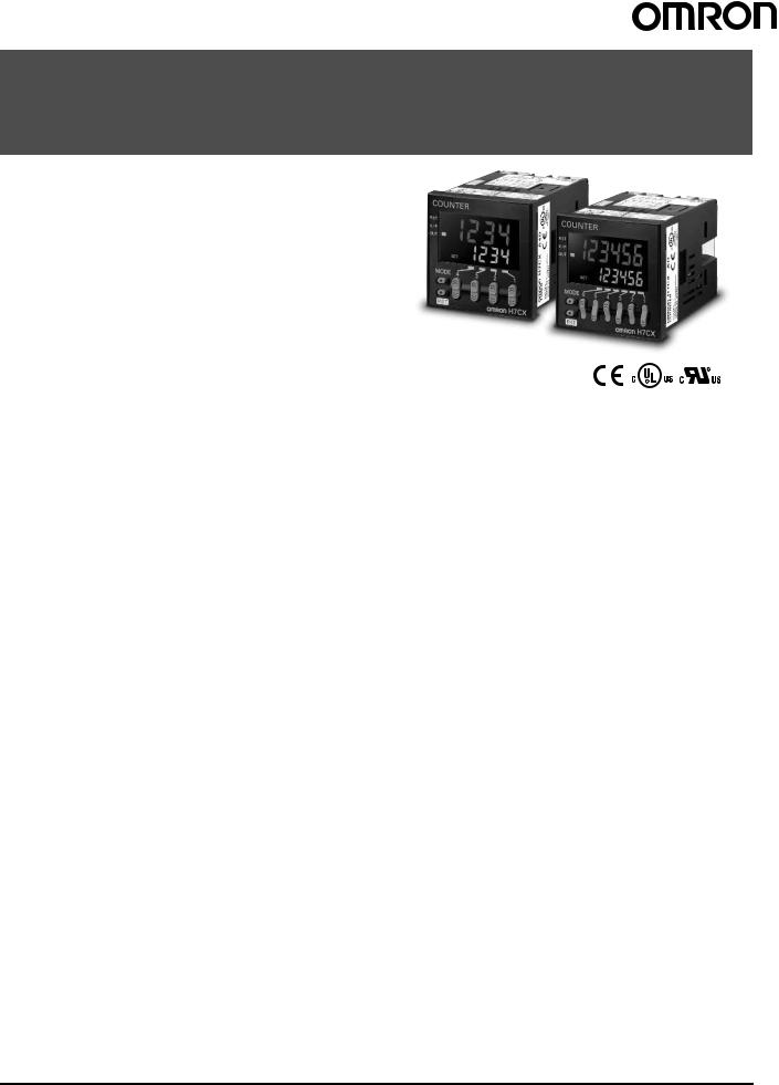
■ Terminal Arrangement
Confirm that the power supply meets specifications before use.
H7CX-A/-A4
1-stage Contact Output
|
|
Reset |
CP2 |
CP1 |
Total reset |
|
0 V |
|
|
|
|
(−) |
6 |
7 |
8 |
9 |
10 |
|
|
|
|
|
|
Sensor, etc. |
|
|
|
|
|
(+) |
12 VDC |
|
Unused |
|
Unused |
|
|
|
|
||
|
11 |
|
12 |
|
13 |
External power |
|
|
|
|
|
supply |
|
|
|
|
|
|
1 |
2 |
3 |
4 |
5 |
|
|
|
OUT |
||
H7CX-AS/-A4S
1-stage Transistor Output
|
|
Reset |
CP2 |
CP1 |
Total reset |
|
0 V |
|
|
|
|
(−) |
6 |
7 |
8 |
9 |
10 |
|
|
|
|
|
|
Sensor, etc. |
|
Unused |
|
Unused |
|
(+) |
|
|
|
||
12 VDC |
|
|
|
|
|
|
11 |
|
12 |
|
13 |
External power |
|
|
|
|
|
supply |
|
|
|
|
|
|
1 |
2 |
3 |
4 |
5 |
|
|
|
OUT |
||
H7CX-A11/-A114/-A11D1/-A114D1
1-stage Contact Output
Reset
CP1
CP2 |
|
|
|
Internal circuit |
Total reset |
|
5 |
6 |
7 |
4 |
|
|||
|
|
|
8 |
|
0 V |
3 |
|
|
9 |
(−) |
2 |
|
|
10 |
|
1 |
|
||
Sensor, etc. |
|
11 |
||
(+) |
12 VDC |
|
|
External power supply |
|
|
OUT |
(−) (+)
Note: Do not connect unused terminals as relay terminals.
H7CX-AD/-A4D
1-stage Contact Output
0 V |
Reset |
|
CP2 |
|
CP1 |
|
Total reset |
|||||
|
|
|
|
|
|
|
|
|
|
|
|
|
6 |
7 |
8 |
9 |
10 |
Unused |
|
Unused |
|
Unused |
11 |
|
12 |
|
13 |
1 |
2 |
3 |
4 |
5 |
(−) |
|
OUT |
||
|
(+) |
|
|
|
Note: Terminals 1 and 6 are connected internally.
H7CX-ASD/-A4SD
1-stage Transistor Output
0 V |
Reset |
|
CP2 |
|
CP1 |
|
Total reset |
|||||
|
|
|
|
|
|
|
|
|
|
|
|
|
6 |
7 |
8 |
9 |
10 |
Unused |
|
Unused |
|
Unused |
11 |
|
12 |
|
13 |
1 |
2 |
3 |
4 |
5 |
(−) |
|
|
OUT |
|
(+) |
|
|
||
Note: Terminals 1 and 6 are connected internally.
H7CX-A11S/-A114S/-A11SD1
1-stage Transistor Output
Reset
CP1
|
CP2 |
|
|
Internal circuit |
|
Total reset |
5 |
6 |
7 |
|
|
|||
|
|
4 |
|
8 |
(−) |
0 V |
3 |
|
9 |
|
2 |
|
10 |
|
|
|
|
||
Sensor, etc. |
1 |
11 |
||
(+) |
12 VDC |
|
|
|
|
|
|
|
|
External power supply |
|
|
OUT |
|
|
|
|
|
|
|
|
(−) |
|
(+) |
Multifunction Preset Counter H7CX-A |
9 |
H7CX-AW/-A4W/-AWD1
2-stage Contact Output
|
|
Reset 1 |
CP2 |
CP1 |
Reset 2 |
|
|
0 V |
|
|
|
|
|
(−) |
6 |
7 |
8 |
9 |
10 |
|
|
|
|
|
|
|
|
Sensor, etc. |
|
|
|
|
|
|
(+) |
12 VDC |
|
|
|
|
|
|
11 |
|
12 |
|
13 |
OUT1 |
External power |
|
|
|
|
|
|
supply |
|
|
|
|
|
|
|
1 |
2 |
3 |
4 |
5 |
|
|
|
|
|
OUT2 |
|
|
|
(−) |
|
(+) |
|
|
|
H7CX-AWSD/-A4WSD
2-stage Transistor Output
0 V |
Reset 1 |
CP2 |
CP1 |
Reset 2 |
|
|
|
|
|
|
|
6 |
7 |
8 |
9 |
10 |
|
Unused |
|
|
|
|
|
11 |
|
12 |
|
13 |
OUT1 |
1 |
2 |
3 |
4 |
5 |
|
(−) |
|
|
OUT2 |
|
|
(+) |
|
|
|
|
Note: 1. Terminals 1 and 6 are connected internally.
2. Do not connect unused terminals as relay terminals.
H7CX-AWS/-AWSD1
2-stage Transistor Output
|
|
Reset 1 |
CP2 |
CP1 |
Reset 2 |
|
|
0 V |
|
|
|
|
|
(−) |
6 |
7 |
8 |
9 |
10 |
|
|
|
|
|
|
|
|
Sensor, etc. |
|
|
|
|
|
|
(+) |
12 VDC |
|
|
|
|
|
|
11 |
|
12 |
|
13 |
OUT1 |
External power |
|
|
|
|
|
|
supply |
|
|
|
|
|
|
|
1 |
2 |
3 |
4 |
5 |
|
|
|
|
|
OUT2 |
|
|
|
(−) |
|
(+) |
|
|
|
H7CX-AUSD1
1 or 2-stage Transistor Output
|
|
Reset 1 |
CP2 |
CP1 |
Reset 2 |
|
|
0 V |
|
|
|
|
|
(−) |
6 |
7 |
8 |
9 |
10 |
|
|
|
|
|
|
|
|
Sensor, etc. |
|
|
|
|
|
|
(+) |
12 VDC |
|
|
|
|
|
|
11 |
|
12 |
|
13 |
OUT1 or 2 |
External power |
|
|
|
|
|
|
supply |
|
|
|
|
|
|
|
1 |
2 |
3 |
4 |
5 |
|
|
|
|
OUT 1 or 2 |
|
||
|
(−) |
|
(+) |
|
|
|
Note: Each output can be flexibly allocated to either stage 1 or 2 in function selection mode.
H7CX-AU/-AUD1 |
|
|
|
|
|
|
1-stage Contact, 1-stage Transistor Output |
||||||
|
|
Reset 1 |
CP2 |
CP1 |
Reset 2 |
|
|
0 V |
|
|
|
|
|
(−) |
6 |
7 |
8 |
9 |
10 |
|
|
|
|
|
|
|
|
Sensor, etc. |
|
|
|
|
|
|
(+) |
12 VDC |
|
|
|
|
|
|
11 |
|
12 |
|
13 |
OUT1 or 2 |
External power |
|
|
|
|
|
|
supply |
|
|
|
|
|
|
|
1 |
2 |
3 |
4 |
5 |
|
|
|
|
OUT 1 or 2 |
|
||
(−) 
 (+)
(+)
Note: Each output can be flexibly allocated to either stage 1 or 2 by setting in function selection mode.
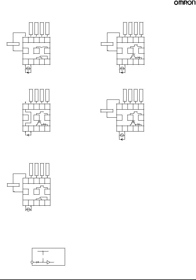
■ Input Circuits
CP1, CP2, Reset/Reset 1, and Total Reset/Reset 2 Input
+14 V
 1 kΩ
1 kΩ
IN |
Internal |
|
circuit |
||
|
Note: The circuit shown above is for no-voltage input (NPN input).
10 |
Multifunction Preset Counter H7CX-A |
■ Input Connections
The inputs of the H7CX are no-voltage (short-circuit or open) inputs or voltage inputs. When using as a tachometer, CP2 input and total reset/reset 2 input are not available.
No-voltage Inputs (NPN Inputs)
Open Collector |
|
|
|||
PLC or |
|
|
|
|
|
sensor |
|
Reset/reset1 input |
inputCP2 |
inputCP1 |
reset/resetTotal 2 input |
|
Input |
||||
|
0 V |
|
|
|
|
H7CX-A@ |
6 |
7 |
8 |
9 |
10 |
H7CX-A11@ |
3 7 5 6 4 |
Operates when the transistor turns ON.
Voltage Output |
|
|
|
|||
Sensor |
|
|
Reset/reset1 input |
|
|
reset/resetTotal 2 input |
|
|
Input |
inputCP2 |
inputCP1 |
||
|
|
0 V |
|
|
|
|
H7CX-A@ |
6 |
7 |
8 |
|
9 |
10 |
H7CX-A11@ |
3 7 5 6 4 |
Operates when the transistor turns ON.
Contact Input |
DC Two-wire Sensor |
||||||
|
|
|
|
|
|
|
|
|
|
Input |
Reset/reset1 input |
inputCP2 |
inputCP1 |
reset/resetTotal 2 input |
|
|
0 V |
|
|
|
|
H7CX-A@ |
6 |
7 |
8 |
9 |
|
10 |
H7CX-A11@ |
3 |
7 |
5 |
6 |
|
4 |
Operates when the contact turns ON.
|
Input |
|
Reset/reset 1 input |
CP2 input |
CP1 input |
Total reset/reset 2 input |
H7CX-A@ |
6 |
7 |
8 |
9 |
|
10 |
H7CX-A11@ |
3 |
7 |
5 |
6 |
|
4 |
Operates when the transistor turns ON.
No-voltage Input Signal Levels
No-contact input |
Short-circuit level |
|
Transistor ON |
|
Residual voltage: 3 V max. |
|
Impedance when ON: 1 kΩ max. |
|
(The leakage current is 5 to 20 mA when the |
|
impedance is 0 Ω .) |
|
Open level |
|
Transistor OFF |
|
Impedance when OFF: 100 kΩ min. |
Contact input |
Use contact which can adequately switch |
|
5 mA at 10 V. |
|
Maximum applicable voltage: 30 VDC max. |
|
|
Voltage Inputs (PNP Inputs)
No-contact Input
(NPN Transistor)
Sensor |
|
|
Reset/reset1 input |
|
|
reset/resetTotal 2 input |
|
|
Input |
inputCP2 |
inputCP1 |
||
|
|
0 V |
|
|
|
|
H7CX-A@ |
6 |
7 |
8 |
9 |
|
10 |
H7CX-A11@ |
3 7 5 6 4 |
Operates when the transistor turns OFF.
No-contact Input
(PNP Transistor)
Sensor |
|
|
Reset/reset1 input |
|
|
reset/resetTotal 2 input |
|
|
Input |
inputCP2 |
inputCP1 |
||
|
|
0 V |
|
|
|
|
H7CX-A@ |
6 |
7 |
8 |
9 |
|
10 |
H7CX-A11@ |
3 7 5 6 4 |
Operates when the transistor turns ON.
Voltage Input Signal Levels
High level (Input ON): |
4.5 to |
30 VDC |
Low level (Input OFF): |
0 to 2 |
VDC |
Maximum applicable voltage: |
30 VDC max. |
|
Input resistance: |
Approx. 4.7 kΩ |
|
Applicable Two-wire Sensor
Leakage current: 1.5 mA max.
Switching capacity: 5 mA min.
Residual voltage: 3 VDC max.
Operating voltage: 10 VDC
Contact Input
|
|
Input |
Reset/reset1 input |
inputCP2 |
inputCP1 |
reset/resetTotal 2 input |
|
|
0 V |
|
|
|
|
H7CX-A@ |
6 |
7 |
8 |
9 |
|
10 |
H7CX-A11@ |
3 |
7 |
5 |
6 |
|
4 |
Operates when the contact turns ON.
Multifunction Preset Counter H7CX-A |
11 |

Nomenclature
|
Indicators |
|
|
A Reset Indicator (Orange) |
1 |
|
|
2 |
|
||
Lit when the reset input (1) or reset key |
7 |
||
is ON. |
|
3 |
|
B Key Protection Indicator (Orange) |
4 |
8 |
|
C Control Output Indicator (Orange) |
5 |
|
|
6 |
|
||
OUT: |
One stage |
9 |
11 |
OUT1, OUT2: |
Two stages |
10 |
12 |
D Total Count Indicator |
Front view of 4-digit model |
Lit when the total count value is |
|
displayed. |
|
EBatch Indicator
Lit when the batch count value is displayed.
F Set Value 1, 2 Stage Indicator |
1 |
|
GPresent Value (Main Display) |
2 |
7 |
Character height: 11.5 mm (6-digit: 9mm) |
3 |
|
HSet Value (Sub-display) |
4 |
8 |
Character height: 6 mm |
5 |
|
6 |
|
|
|
|
|
|
9 |
11 |
|
10 |
|
|
|
|
|
|
Front view of 6-digit model |
|
13 |
14 |
Operation Keys
IMode Key
Used to switch mode and setting items.
JReset Key
The operation of the reset function depends on the configuration selected as shown in the table below.
KUp Keys: 1 to 4 (6-digit models: 1 to 6)
LDown Keys: 1 to 4
Switches
MKey Protect Switch
(Factory setting) OFF 
 ON
ON
 DIP Switch
Reset Operation by Reset Key
Configuration |
Reset operation |
|
|
1-stage/2-stage |
Resets the present value and outputs. |
counter |
|
|
|
Total and preset |
• Resets the present value and outputs. |
counter |
• When the total count value is displayed, resets |
|
the present value, the total count value, and |
|
outputs. |
|
|
Batch counter |
• Resets the present value and OUT2. |
|
• When the batch count value is displayed, |
|
resets the present value, the batch count |
|
value, and outputs. |
|
|
Dual counter |
Resets the CP1 present value, CP2 present val- |
|
ue, dual count value, and outputs. |
|
|
Tachometer |
Maintains the measured value and outputs (hold |
|
function). |
|
|
12 |
Multifunction Preset Counter H7CX-A |

Dimensions
Note: All units are in millimeters unless otherwise indicated.
■ Counter (without Flush Mounting Adapter)
Screw-terminal Models with External Power Supplies (Flush Mounting)
• H7CX-A |
• H7CX-AW |
• H7CX-AU |
• H7CX-AS |
• H7CX-AWS |
• H7CX-AUD1 |
• H7CX-A4 |
• H7CX-A4W |
• H7CX-AUSD1 |
•H7CX-A4S • H7CX-AWD1
•H7CX-AWSD1
48× 48 |
|
|
|
|
6 |
|
|
100 |
|
|
|
|
|
|||
|
|
|
|
|
|
|
|
|
|
|
|
|
|
|
|
|
|
|
|
|
|
|
|
|
|
|
|
|
|
|
|
|
|
|
|
|
|
|
|
|
|
|
|
|
|
|
|
|
|
|
|
|
|
|
|
|
|
|
|
|
|
|
|
|
|
|
|
|
|
|
|
|
|
|
|
|
|
|
|
|
|
|
|
|
|
|
|
|
|
|
|
|
|
|
|
|
|
|
|
|
|
|
|
|
|
|
|
|
|
|
|
|
|
|
|
|
|
|
|
|
|
|
|
|
|
|
|
|
|
|
|
|
|
|
|
44.8× 44.8
Note: M3.5 terminal screw (effective length: 6 mm)
Screw-terminal Models without External Power Supplies (Flush Mounting)
• H7CX-AD |
• H7CX-AWSD |
• H7CX-ASD |
• H7CX-AWSD |
•H7CX-A4D
•H7CX-A4SD
48× 48 |
6 |
64 |
44.8× 44.8
Note: M3.5 terminal screw (effective length: 6 mm)
11-pin Socket Models (Flush Mounting/Surface Mounting)
• H7CX-A11 |
• H7CX-A114 |
|
|
|
|
|
|
|
|
|
|||||||
• H7CX-A11S |
• H7CX-A114S |
|
|
|
|
|
|
|
|
|
|||||||
• H7CX-A11D1 |
• H7CX-A114D1 |
|
|
|
|
|
|
|
|
|
|||||||
• H7CX-A11SD1 |
|
|
|
|
|
|
|
|
|
|
|
|
|
|
|
|
|
|
|
|
|
48× 48 |
|
|
|
|
6 |
|
|
14.4 |
|
|
|
||
|
|
|
|
|
|
|
|
|
|
72.5 |
|
|
|
|
|
||
|
|
|
|
|
|
|
|
|
|
|
|
|
|
|
|
|
|
|
|
|
|
|
|
|
|
|
|
|
|
|
|
|
|
|
|
|
|
|
|
|
|
|
|
|
|
|
|
|
|
|
|
|
|
44.8× 44.8
Multifunction Preset Counter H7CX-A |
13 |

■ Dimensions with Flush Mounting Adapter
Screw-terminal Models with External Power Supplies
(Provided with Adapter and Waterproof Packing)
• H7CX-A |
• H7CX-AW |
• H7CX-AU |
|
|
|
|
|
|
|
|
|||||
• H7CX-AS |
• H7CX-AWS |
• H7CX-AUD1 |
|
|
|
|
|
|
|
|
|||||
• H7CX-A4 |
• H7CX-A4W |
• H7CX-AUSD1 |
|
|
|
|
|
|
|
|
|||||
• H7CX-A4S |
• H7CX-AWD1 |
|
|
|
|
Y92S-29 (provided) |
|
|
|
|
|
|
|
|
|
|
|
|
|
Waterproof Packing |
Panel |
|
|
|
|
|
|
|
|||
|
• H7CX-AWSD1 |
|
|
|
|
Y92F-30 (provided) |
|||||||||
|
|
|
|
|
|
|
|
||||||||
|
|
|
|
|
|
|
|
|
Flush Mounting Adapter |
||||||
|
|
|
|
|
|
|
|
|
|
|
|
|
|
|
|
|
|
|
|
|
|
|
|
|
|
|
|
|
|
|
|
|
|
|
|
|
|
|
|
|
|
|
|
|
|
|
|
|
|
|
|
|
|
|
|
|
|
|
|
|
|
|
|
|
|
|
|
|
|
|
|
|
|
|
|
|
|
|
|
|
|
|
|
|
|
|
|
|
|
|
|
|
|
|
|
|
|
|
|
|
|
|
|
|
|
|
|
|
|
|
|
|
|
|
|
|
|
|
|
|
|
|
|
|
|
|
|
|
58 |
(51) |
|
|
48 |
7.5 |
98.5 |
Screw-terminal Models without External Power Supplies |
|||
(Provided with Adapter and Waterproof Packing) |
|
||
• H7CX-AD |
• H7CX-AWSD |
|
|
• H7CX-ASD |
• H7CX-A4WSD |
Y92S-29 (provided) |
|
• H7CX-A4D |
|
Panel Y92F-30 (provided) |
|
|
Waterproof Packing |
||
• H7CX-A4SD |
|
||
|
|
Flush Mounting Adapter |
|
|
|
|
|
|
58 |
(51) |
|
|
48 |
7.5 |
62.5 |
11-pin Socket Models |
|
|
|
(Adapter and Waterproof Packing Ordered Separately) |
|
||
• H7CX-A11 |
• H7CX-A114 |
|
|
• H7CX-A11S |
• H7CX-A114S |
|
|
• H7CX-A11D1 |
• H7CX-A114D1 |
|
|
• H7CX-A11SD1 |
Y92S-29 (order separately) |
Panel Y92F-30 (order separately) |
|
|
|||
|
Waterproof Packing |
Flush Mounting Adapter |
|
|
58 |
(51) |
|
|
48 |
7.5 |
98.7 |
■ Dimensions with Front Connecting Socket
|
H7CX |
|
-A11 @ |
112 |
109.7 |
P2CF-11
Note: These dimensions vary with the kind of DIN track (reference value).
Panel Cutouts
Panel cutouts are as shown below.
(according to DIN43700).
60 min.
45+0−0.6
45+0−0.6
60 min. 15 min.
Note: 1. The mounting panel thickness should be 1 to 5 mm.
2.To allow easier operability, it is recommended that Adapters are mounted so that the gap between sides with hooks is at least 15 mm (i.e., so that the panel cutout interval is at least 60 mm).
3.It is possible to mount counters side by side, but only in the direction without the hooks.
If they are mounted side-by-side, water-resistant specifications cannot be ensured.
n side by side mounting
A
A = (48n − 2.5)+10
With Y92A-48F1 attached.
A = {48n−2.5 + (n−1) x 4}+10
With Y92A-48 attached.
A = (51n−5.5)+10
P3GA-11
(order separately) Back Connecting Socket
14 |
Multifunction Preset Counter H7CX-A |

■ Accessories (Order Separately)
Note: All units are in millimeters unless otherwise indicated.
Track Mounting/Front Connecting Socket |
|
|
|
|
|
|
|
|
|
|
|||||||||||||||
P2CF-11 |
|
|
Eleven, |
3 |
|
4.5 |
|
|
|||||||||||||||||
|
|
|
|
|
|
||||||||||||||||||||
|
|
|
M3.5 x 7.5 sems |
7.8 |
|
|
|
|
|
|
|
|
|
|
|||||||||||
|
|
|
|
|
|
|
|
|
|
|
|
|
|
|
|
|
|
|
|
|
|
|
|
|
Terminal Arrangement/ |
|
|
70 max. |
|
|
|
|
|
|
|
|
|
|
|
|
|
|
|
|
|
|
|
||||
|
|
|
|
|
|
|
|
|
|
|
|
|
|
|
35.4 |
|
Internal Connections |
||||||||
|
|
|
|
|
|
|
|
|
|
|
|
|
|
|
|
|
|
|
|
|
|
||||
|
|
|
|
|
|
|
|
|
|
|
|
|
|
|
|
|
|
|
|
|
|||||
|
|
|
|
|
|
|
|
|
|
|
|
|
|
|
Two, 4.5-dia. |
|
|
|
|
|
|
|
|
|
(Top View) |
|
|
|
|
|
|
|
|
|
|
|
|
|
|
|
holes |
|
|
|
|
|
|
|
|
|
|
|
4 |
|
|
|
|
|
|
|
|
|
|
|
|
|
|
|
|
|
|
|
|
|
|
||
|
|
|
|
|
|
|
|
|
|
|
|
|
|
|
|
|
|
|
|
|
|
|
|
|
|
|
|
|
|
|
|
|
|
|
|
|
50 max. |
|
|
31.2 max. |
|
||||||||||
P2CF-11-E (Finger-safe Terminal Type) |
|
|
|||||||||||||||||||||||
|
|
|
|
|
|
|
|
|
|
||||||||||||||||
Conforming to VDE0106/P100 |
|
|
|
|
|
|
|
|
|
|
|
||||||||||||||
|
|
Eleven, |
|
|
|
|
|
|
|
|
|
|
|
||||||||||||
|
|
M3.5 x 7.5 sems |
7.8 |
5 |
4.5 |
|
|||||||||||||||||||
|
|
|
|
|
|
|
|
|
|
|
|
|
|
|
|
|
|
|
|
|
|
|
|
|
|
|
|
|
|
|
|
|
|
|
|
|
|
|
|
|
|
3 |
|
|
|
|
|
|
|
|
|
|
|
|
|
|
|
|
|
|
|
|
|
|
|
|
1.2 |
|
|
|
|
|
|
|
|
|
|
|
|
70 max. |
|
|
|
|
|
|
|
|
|
|
|
|
|
|
|
35.4 |
|
||||||
|
|
|
|
|
|
|
|
|
|
|
|
|
|
|
|||||||||||
|
|
|
|
|
|
|
|
|
|
|
|
|
|
|
Two, 4.5-dia. |
|
|
|
|
|
|
|
|
|
|
|
|
|
|
|
|
|
|
|
|
|
|
|
|
|
holes |
|
|
|
|
|
|
|
|
|
|
|
4 |
|
|
|
|
|
|
|
|
|
|
|
|
|
|
|
|
|
|
|
|
|
|
||
|
|
|
|
|
|
|
|
|
|
|
|
|
|
|
|
|
|
|
|
|
|
||||
|
|
|
|
|
|
40±0.2 |
|
|
|
|
|
|
30 |
|
|
|
|
|
|
||||||
|
|
|
|
|
|
|
|
|
|
|
|
|
|
|
|
|
|
|
|
|
|||||
|
|
|
|
|
|
|
|
|
|
|
|
|
|
|
|
|
|
|
|
|
|
|
|
|
|
|
|
|
|
|
|
|
|
|
|
|
|
|
|
|
|
|
|
|
|
|
|
|
|
||
|
|
|
|
|
|
|
|
|
|
50 max. |
|
|
31.2 max. |
|
|||||||||||
Back Connecting Socket |
|
|
|
||||||||||||||||||||||
|
|
|
|
|
|
|
|
|
|
|
|||||||||||||||
P3GA-11 |
|
|
|
|
|
|
27 dia. |
|
|
|
|
|
|
|
|
|
|
Terminal Arrangement/ |
|||||||
|
|
|
|
|
|
|
|
|
|
|
|
|
|
|
|
|
Internal Connections |
||||||||
|
|
|
|
|
|
|
|
|
|
|
|
|
|
|
|
|
|
|
|
|
|
|
|
|
(Bottom View) |
|
|
|
|
|
|
|
|
|
|
|
|
|
|
|
|
|
|
|
|
||||||
|
|
45 |
|
|
|
|
|
|
|
|
|
|
|
|
|
|
25.6 |
|
|
||||||
|
|
|
|
|
|
|
|
4.5 |
|
6.2 |
|
|
|||||||||||||
|
45 |
|
|
|
|
|
|
||||||||||||||||||
|
|
|
|
|
|
|
|
|
|
|
|
|
|
|
|
|
16.3 |
|
|
|
|
|
|
||
Note: Finger protection can be ensured by using in combination with the Y92A-48G Terminal Cover.
Finger-safe Terminal Cover |
|
|
Conforming to VDE0106/P100 |
|
|
Y92A-48G |
Twelve, 6.4-dia. holes |
|
(Attachment for P3GA-11 |
|
|
|
|
|
Socket) |
|
|
34 |
47.7 x 47.7 |
48 x 48 |
16.5 24.6 27.6
47.4
Surface Mounting Holes
Two, 4.5 dia. or two, M4
40±0.2
Note: Track mounting is also possible.
Multifunction Preset Counter H7CX-A |
15 |

Hard Cover |
Soft Cover |
Y92A-48 |
Y92A-48F1 |
Note: 1. Depending on the operating environment, the condition of resin products may deteriorate, and may shrink or become harder. Therefore, it is recommended that resin products are replaced regularly.
2.The H7CX’s panel surface is water-resistive (conforming to IP66) and so even if drops of water penetrate the gaps between the keys, there will be no adverse effect on internal circuits. If, however, there is a possibility of oil being present on the operator’s hands, use the Soft Cover. The Soft Cover ensures protection equivalent to IP54F against oil. Do not, however, use the H7CX in locations where it would come in direct contact with oil.
Flush Mounting Adapter |
Waterproof Packing |
(provided with screw-terminal models) |
(provided with screw-terminal models) |
Y92F-30 |
Y92S-29 |
Mounting Track
PFP-100N, PFP-50N
|
|
|
|
7.3±0.15 |
|
4.5 |
|
|
|
|
|
|
|
|
|
35±0.3 |
27±0.15 |
15 25 |
25 |
25 |
25 * |
1 |
|
|
10 |
1,000 (500) |
|
10 |
|
|
|
|
|||
|
|
(See note.) |
|
|
|
When using the Y92S-29, the degree of protection for the H7CX's panel surface conforms to NEMA4, UL Type 4X, and IP66. (Depending on the operating environment, the condition of the panel may deteriorate, shrink, or become harder. Therefore, regular replacement is recommended.)
PFP-100N2
|
|
|
|
|
|
|
|
16 |
4.5 |
|
|
|
|
|
|
|
|
|
|
|
|
|
|
|
35±0.3 27 24 |
29.2 |
15 |
25 |
25 |
25 |
25 |
15 |
1 |
1.5 |
|
|
|
10 |
|
|
10 |
|
||
|
|
1,000 |
|
|
|
|
||
|
|
|
|
|
|
|
|
|
Note: The values shown in parentheses are for the PFP-50N.
End Plate |
|
|
|
Spacer |
PFP-M |
|
|
|
PFP-S |
|
|
10 |
|
|
|
|
6.2 |
1.8 |
|
|
|
|
|
|
|
|
1 |
|
|
50 |
|
1.8 |
35.5 |
35.3 |
|
|
|
|
|
11.5 |
M4 x 8 |
1.3 |
|
|
10 |
|
|
||
4.8 |
|
|
||
|
pan head |
|
|
screw
|
16 |
5 |
12 |
34.8
44.3
16.5
16 |
Multifunction Preset Counter H7CX-A |

Operating Procedures
■ Setting Procedure Guide
Setting for Counter Operation
(1-stage/2-stage Counter, Total and Preset Counter, Batch Counter, Dual Counter)
When Using Basic Settings Only
Basic Settings
•Counting speed (30 Hz, 5 kHz)
•Input mode (UP, DOWN)
•Output mode (N, F, C, K-1)
•One-shot output time (0.5 s, 0.05 s)(See note 2.)
•Reset input signal width (20 ms, 1 ms)
•NPN/PNP input mode (NPN, PNP)
The settings can be performed easily with the DIP switch.For details on the setting methods, refer to page 18.
1 |
2 |
3 |
4 |
5 |
6 |
7 |
8 |
ON
OFF
When Using Settings Other than the Above
All the functions can be set with the operation keys.
For details on the setting methods, refer to page 19.
Other Settings
•Input mode (UP/DOWN A, UP/DOWN B, UP/DOWN C)
•Output mode (R, P, Q, A, K-2, D, L, H)
•One-shot output time (except for 0.5 s and 0.05 s) (See note 2.)
When Using Advanced Functions
Settings for advanced functions other than the basic settings above can be performed with the operation keys.For details on the setting methods, refer to page 19.
Advanced Functions
•Dual count calculating mode
•Output 1 time (for 2-stage counter)
•Decimal point position
•Prescale value
•Display color
•Output allocation
•Key protect level
Note: 1. At the time of delivery, the H7CX is set to the 1-stage counter (2-stage counter for H7CX-AW@/-A4W@ models) configuration. 2. Set to output 2 time when using as a 2-stage counter or batch counter.
Setting for Tachometer Operation
When Using Basic Settings Only
Basic Settings
•Counting speed (30 Hz, 10 kHz)
•Output mode (HI-LO, AREA, HI-HI, LO-LO)
•Average processing (OFF, 2, 4, 8 times)
•NPN/PNP input mode (NPN, PNP)
The settings can be performed easily with the DIP switch.For details on the setting methods, refer to page 30.
1 |
2 |
3 |
4 |
5 |
6 |
7 |
8 |
ON
OFF
When Using Advanced Functions
Settings for advanced functions other than the basic settings above can be performed with the operation keys.For details on the setting methods, refer to page 31.
Advanced Functions
•Decimal point position
•Prescale value
•Auto-zero time
•Startup time
•Display color
•Output allocation
•Key protect level
Note: At the time of delivery, the H7CX is set to the 2-stage counter (1-stage counter for H7CX-AU@ models) configuration.
Multifunction Preset Counter H7CX-A |
17 |

■ Operating Procedures (Counter Function)
Settings for Basic Operations
Settings for basic functions can be performed with just the DIP switch.
Be sure to set pin 1 to ON.
1 |
2 |
|
3 |
|
4 |
|
5 |
|
6 |
|
7 |
|
8 |
|
||||
ON |
|
|
|
|
|
|
|
|
|
|
|
|
|
|
|
|
|
|
|
|
|
|
|
|
|
|
|
|
|
|
|
|
|
|
|
|
|
|
|
|
|
|
|
|
|
|
|
|
|
|
|
|
|
|
|
|
OFF |
|
|
|
|
|
|
|
|
|
|
|
|
|
|
|
|
|
|
|
|
|
|
|
|
|
|
|
|
|
|
|
|
|
|
|
||
|
|
|
|
|
|
|
|
|
|
|
|
|
|
|
|
|
|
|
|
|
|
|
|
|
|
|
|
|
|
|
|
|
|
|
|
|
|
|
|
Note: All of the pins are factory-set to OFF. |
|
|
||||||
|
|
|
|
|
|
|
|
|
|
|
|
Item |
OFF |
ON |
|
|
|
|
|
|
|
|
|
|
|
|
|
|
|
|
|
|
1 |
DIP switch settings en- |
Disabled |
Enabled |
|
|
|
|
|
|
|
|
able/disable |
|
|
|
|
|
|
|
|
|
|
|
|
|
|
|
|
|
|
|
|
2 |
Counting speed |
30 Hz |
5 kHz |
|
|
|
|
|
|
|
|
|
|
|
|
|
|
|
|
|
|
3 |
Input mode |
UP (increment) |
DOWN (decre- |
|
|
|
|
|
|
|
|
|
|
ment) |
|
|
|
|
|
|
|
|
|
|
|
|
|
|
Pin 4 |
Pin 5 |
Output mode |
|
4 |
Output mode |
Refer to the table on the right. |
||||||||
|
|
|
|
|
|
|||||
|
|
|
|
|
|
|
OFF |
OFF |
N |
|
5 |
|
|
|
|||||||
|
|
|
|
|
|
|
|
|
||
6 |
One-shot output time |
0.5 s |
0.05 s |
|
|
|
ON |
OFF |
F |
|
|
|
|
|
|
|
|||||
|
(See note.) |
|
|
|
|
|
OFF |
ON |
C |
|
|
|
|
|
|
|
|
|
|
|
|
7 |
Reset input signal width |
20 ms |
1 ms |
|
|
|
ON |
ON |
K-1 |
|
|
|
|
|
|
|
|
|
|
|
|
8 |
NPN/PNP input mode |
NPN |
PNP |
|
|
|
|
|
|
|
|
|
|
|
|
|
|
|
|
|
|
Note: Set to one-shot output 2 time when using as a 2-stage counter or batch counter.
Easy Confirmation of Switch Settings Using Indicators
The ON/OFF status of the DIP switch pins can be
confirmed using the front display. For details, refer to page 36.
Note: 1. Be sure to set pin 1 of the DIP switch to ON. If it is set to OFF, the DIP switch settings will not be enabled.
2.Changes to DIP switch settings are enabled when the power is turned ON.
3.When setting input modes, output modes, or output times that cannot be set with the DIP switch, all of the settings have to be made using the operation keys. For details on the setting methods, refer to page 19. When making settings using the operation keys, be sure to set pin 1 of the DIP switch to OFF.
Switching to Total and Preset Counter, Batch Counter, and Dual Counter Operation (See note.)
The H7CX is factory-set to the 1-stage counter (2-stage counter for H7CX-AW@/- A4W@ models) configuration. To change to a different configuration, use the procedure shown on the right. For details, refer to page 36.
Note: This includes changing to the 2- stage counter (or 1-stage counter) configuration.
Power ON
Configuration selection mode |
Run mode |
Hold down for
MODE +  1 1 s min. (See note.)
Note: The MODE key must be pressed before the  1 key.
Select the configuration using the  and
and  keys (
 key with 6-digit models).
(1-stage |
(2-stage |
(Total and |
(Batch |
(Dual |
(Tachometer) |
counter) |
counter) |
preset counter) |
counter) |
counter) |
|
Note: The configurations that can be selected vary with the model.
Advanced-Function Settings
After making DIP switch settings for basic operations, advanced functions (see note) can be added using the operation keys. For details, refer to page 19.
Note: Advanced functions consist of the dual count calculating mode, output 1 time (for 2-stage counter), decimal point position, prescale value, display color, output allocation, and key protect level.
18 Multifunction Preset Counter H7CX-A (Counter Function)

Settings for All Functions
Note: At the time of delivery, the H7CX is set to the 1-stage counter (2-stage counter for H7CX-AW@/-A4W@ models) configuration. When using as a 2-stage (or 1-stage) counter, total and preset counter, batch counter, or dual counter, switch to the configuration using the procedure given on page 36.
Settings that cannot be performed with the DIP switch are performed with the operation keys.
Power ON
Run mode
See note 1. |
See note 2. |
3 s min. |
3 s min. |
|
See note 3. |
|
Input mode |
|
Output mode |
|
See note 6. |
|
One-shot |
|
output |
|
time |
mode |
|
settingFunction |
Counting |
|
speed |
|
Reset input |
|
signal |
|
width |
|
Decimal |
|
point |
|
position |
|
Prescale |
|
value |
|
NPN/PNP |
|
input mode |
|
Display color |
|
Output |
|
allocation |
|
Key protect |
|
level |
For details on operations and display in run mode, refer to page 22. The display depends on the configuration used.
Note: 1. If the mode is switched to the function setting mode during operation, operation will continue.
2.Changes made to settings in function setting mode are enabled for the first time when the mode is changed to run mode. Also, when settings are changed, the counter is reset (present value initialized and output turned OFF) on returning to run mode.
The characters displayed in reverse video are the default settings.
When performing settings with operation keys only, set pin1 of the DIP switch to OFF (factory setting). If pin 1 of the DIP switch is set to ON, the setting items indicated by 
 will not be displayed.
Set each setting item using the |
r |
r keys. ( r |
key only for 6-digit models) |
Note 3:
When using as a dual counter:
Dual count calculating mode
See note 4. See note 4.
|
|
|
|
|
|
|
|
|
|
(UP) |
|
|
(DOWN) (UP/DOWN A) (UP/DOWN B) (UP/DOWN C) |
||||||
|
|
|
|
|
|
|
|
|
See note. |
Note 4: Displayed for output modes other than K-2, D, L, and H only.
(Addition) (Subtraction)
Note: Displayed only when the output mode is K-2, D, L, or H.
See note 5. See note 5.See note 5.See note 5.
|
|
|
|
|
|
|
|
|
|
|
|
|
|
|
|
|
|
(N) |
|
(F) |
|
(C) |
|
(R) |
|
(K-1) |
|
(P) |
|
(Q) |
|
(A) |
|
(K-2) |
|
Note: 5. Display only when the input mode is UP/DOWN A, B, or C with 6-digit models (with H7CX-AU@/-AW@ models only for H).
(0.01s) (0.50s) (99.99s)
Note: Displayed only when the output mode is C, R, K-1, P, Q, A, or K-2.
(30Hz) (5kHz)
(20ms) (1ms)
(D)(L) (H)
Note 6:
When using as a 2-stage counter:
Oneshot output 2 time
Oneshot output 1 time
When using as a batch counter:
Oneshot output 2 time
(0.01s) (0.50s) (99.99s)
Note: Displayed only when the output mode is C, R, K-1, P, Q, A, or K-2.
(Outputs held) (0.01s) (99.99s)
If the output time is 0.00, hold is displayed.
Note 1: Displayed for output modes other than D, L, and H.
Note 2: HOLD cannot be set when the output mode is K-2.
(0.01s) (0.50s) (99.99s)
Note: Displayed only when the output mode is C, R, K-1, P, Q, A, or K-2.
See note 7. |
|
|
|
|
|
|
|
|
|
|
|||
|
|
|
|
|
|
|
|
|
|||||
|
|
|
|
|
|
|
|
|
|
|
|
|
|
|
No decimal |
One digit after |
|
Two digits after |
|
Three digits after |
|||||||
|
point |
|
|
|
|
decimal point |
|
decimal point |
|
decimal point |
|||
See note 7. |
|
|
|
|
|
|
|
|
|
|
|||
|
|
|
|
|
|
|
|
|
|
|
Note 7: The displays for 4-digit models are shown inside |
||
|
|
|
|
|
|
|
|
|
|
parentheses. |
|||
(0.001) |
(1.000) |
(99.999) |
[9.999] |
|
|
|
|||||||
|
|
|
|
|
|
|
|||||||
|
|
|
|
|
|
|
|
|
|
|
|
|
|
|
|
|
|
|
|
|
|
|
|
|
|
|
|
|
|
|
|
|
|
|
|
|
|
|
|
|
|
(NPN (PNP input) input)
|
|
|
|
|
|
(Red) |
|
|
(Green) (Red-green) (Green-red) |
||
Note: Displayed for terminal-block models (except H7CX-A11@) only.
Note: Displayed for H7CX-AU@ models only.
|
|
|
|
|
|
|
|
|
|
(KP-1) |
|
|
(KP-2) |
|
(KP-3) |
|
(KP-4) |
|
(KP-5) |
Multifunction Preset Counter H7CX-A (Counter Function) |
19 |

Explanation of Functions
Input Mode (cntm) (Setting possible using DIP switch.)
Set increment mode (UP), decrement mode (DOWN), or one of the increment/decrement modes (UP/DOWN A, UP/DOWN B, or UP/ DOWN C) as the input mode. Input modes other than UP or DOWN modes cannot be set using the DIP switch and so use the operation keys if other modes are required. (For details on the operation of the input modes, refer to Input Modes and Present Value on page 23.)
Dual Count Calculating Mode (calm)
When using as a dual counter, select either ADD (addition) or SUB (subtraction) as the calculation method for the dual count value. SUB mode can be used only when K-2, D, L, or H is selected as the output mode with 6-digit models.
ADD: Dual count value = CP1 PV + CP2 PV
SUB: Dual count value = CP1 PV − CP2 PV
Output Mode (outm) (Setting possible using DIP switch.)
Set the way that control output for the present value is output. The possible settings are N, F, C, R, K-1, P, Q, A, K-2, D, L, and H. Output modes other than N, F, C, or K-1 cannot be set using the DIP switch and so use the operation keys if other modes are required. The output modes that can be set vary with the model. (For details on the operation of the output modes, refer to Input/Output Mode Settings on page 24.)
One-shot Output Time (otim) (Setting possible using DIP switch.)
Set the one-shot output time (0.01 to 99.99 s) for control output. One-shot output can be used only when C, R, K-1, P, Q, A, or K-2 is selected as the output mode. Output times other than 0.5 s or 0.05 s cannot be set with the DIP switch and so use the operation keys if other settings are required.
One-shot Output 2 Time (otm2) (Setting possible using
DIP switch.)
When using as a 2-stage counter or batch counter, set the one-shot output time (0.01 to 99.99 s) for control output (OUT2). One-shot output can be used only when C, R, K-1, P, Q, A, or K-2 is selected as the output mode. Output times other than 0.5 s or 0.05 s cannot be set with the DIP switch and so use the operation keys if other settings are required.
One-shot Output 1 Time (otm1)
When using as a 2-stage counter, set the one-shot output time (0.01 to 99.99 s) for control output (OUT1). One-shot output can be used only when D, L, or H is selected as the output mode. If the output time is set to 0.00, hold is displayed, and outputs are held. HOLD cannot be set when the output mode is K-2.
Counting Speed (cnts) (Setting possible using DIP switch.)
Set the maximum counting speed (30 Hz/5 kHz) for CP1 and CP2 inputs together. If contacts are used for input signals, set the counting speed to 30 Hz. Processing to eliminate chattering is performed for this setting.
Reset Input Signal Width (iflt) (Setting possible using
DIP switch.)
Set the reset input signal width (20 ms/1 ms) for reset/reset 1 and total reset/reset 2 inputs together. If contacts are used for input signals, set the counting speed to 20 ms. Processing to eliminate chattering is performed for this setting.
Decimal Point Position (dp)
Decide the decimal point position for the present value, CP1/CP2 present values, set value (SV1, SV2), total count value, and dual count set value.
Prescale Value (pscl)
Pulses input to the counter are converted according to the specified prescale value. (Setting range: 0.001 to 99.999 for 6-digit models and 0.001 to 9.999 for 4-digit models.)
Example: To display the feed distance for systems that output 25 pulses for a feed length of 0.5 m in the form @@.@@ m:
1.Set the decimal point position to 2 decimal places.
2.Set the prescale value to 0.02 (0.5÷ 25).
0.5 m
25 pulses
Encoder
NPN/PNP Input Mode (imod)
Select either NPN input (no-voltage input) or PNP input (voltage input) as the input format. The same setting is used for all external inputs. For details on input connections, refer to Input Connections on page 11.
Display Color (colr)
Set the color used for the present value.
|
Output OFF (See note.) |
Output ON (See note.) |
red |
Red (fixed) |
|
|
|
|
grn |
Green (fixed) |
|
|
|
|
r-g |
Red |
Green |
|
|
|
g-r |
Green |
Red |
|
|
|
Note: When using as a 2-stage counter, this is the status of output 2.
Output Allocation (otst)
When using H7CX-AU@ models as a 2-stage counter, the output can be flexibly allocated to either stage 1 or 2.
Transistor output can be allocated to SV1 and contact output for SV2 or vice verse, as in the following table.
H7CX-AU/-AUD1
|
OUT1 |
OUT2 |
off |
Transistor (12-13) |
Contact (3, 4, 5) |
|
|
|
on |
Contact (3, 4, 5) |
Transistor (12-13) |
|
|
|
H7CX-AUSD1
|
OUT1 |
OUT2 |
|
|
|
off |
Transistor (12-13) |
Transistor with diode |
|
|
(3, 4, 5) |
|
|
|
on |
Transistor with diode |
Transistor (12-13) |
|
(3, 4, 5) |
|
|
|
|
20 Multifunction Preset Counter H7CX-A (Counter Function)
 Loading...