


Mitsubishi MUX-2A28VB-E1, MUX-2A59VB-E1, MUX-3A60VB-E1, MUX-3A63VB-E1, MUX-2A70VB-E1 Service Manual
...Revision B:
SPLIT-TYPE, AIR CONDITIONERS
● RoHS PARTS LIST has been added.
Please void OB384 REVISED EDITION-A.
OUTDOOR UNIT
SERVICE MANUAL
HFC |
No. OB384 |
|
REVISED EDITION-B |
||
utilized |
||
R410A |
|
Multi system type
Models
MUX-2A28VB - E1
MUX-2A59VB - E1
MUX-3A60VB - E1
MUX-3A63VB - E1
MUX-2A70VB - E1
MUX-4A73VB - E1
Indoor unit service manual
MSC-CA·VB Series (OB393)
MSC-GA·VB Series (OB385)
CONTENTS
MUX-3A60VB
MUX-3A63VB
NOTE:
•This service manual describes technical data of the outdoor units.
•RoHS compliant products have <G> mark on the spec name plate. For servicing of RoHS compliant products, refer to the RoHS Parts List.
1.TECHNICAL CHANGES ··············
2.PART NAMES AND FUNCTIONS···········
3.INDOOR / OUTDOOR
CORRESPONDENCE TABLE ············
4.SPECIFICATION··················
5.NOISE CRITERIA CURVES ·············
6.OUTLINES AND DIMENSIONS ···········
7.WIRING DIAGRAM ·················
8.REFRIGERANT SYSTEM DIAGRAM ·········
9.PERFORMANCE CURVES ·············
10.ACTUATOR CONTROL···············
11.TROUBLESHOOTING ················
12.DISASSEMBLY INSTRUCTIONS···········
13.PARTS LIST····················
14.RoHS PARTS LIST·················

Revision A:
• WIRING DIAGRAM , REFRIGERANT SYSTEM DIAGRAM and PARTS LIST (Numbers of the terminal blocks) have been changed.
Revision B:
• RoHS PARTS LIST has been added.
1 
 TECHNICAL CHANGES
MUX-A10WV- E1 MUX-2A28VB- E1 MUX-A20WV- E1 MUX-3A60VB- E1
1. Indication of capacity has been changed. (BTU kW)
MUX-A19WV- E1 MUX-2A59VB- E1
MUX-A22WV- E1 MUX-3A63VB- E1
MUX-A25WV- E1 MUX-2A70VB- E1
MUX-A26WV- E1 MUX-4A73VB- E1
1.Indication of capacity has been changed. (BTU kW)
2.Size of stop valve (Gas) has been changed. ([12.7 [9.52)
2
INFORMATION FOR THE AIR CONDITIONER WITH R410A REFRIGERANT
•This room air conditioner adopts HFC refrigerant (R410A) which never destroys the ozone layer.
•Pay particular attention to the following points, though the basic installation procedure is same as that for R22 conditioners.
1As R410A has working pressure approximate 1.6 times as high as that of R22, some special tools and piping parts/ materials are required. Refer to the table below.
2Take sufficient care not to allow water and other contaminations to enter the R410A refrigerant during storage and installation, since it is more susceptible to contaminations than R22.
3For refrigerant piping, use clean, pressure-proof parts/materials specifically designed for R410A. (Refer to 2. Refrigerant piping.)
4Composition change may occur in R410A since it is a mixed refrigerant. When charging, charge liquid refrigerant to prevent composition change.
Refrigerant
Refrigeration |
oil |
|
New refrigerant |
Previous refrigerant |
Refrigerant |
R410A |
R22 |
|
|
|
Composition (Ratio) |
HFC-32: HFC-125 (50%:50%) |
R22 (100%) |
|
|
|
Refrigerant handling |
Pseudo-azeotropic refrigerant |
Single refrigerant |
|
|
|
Chlorine |
Not included |
Included |
|
|
|
Safety group (ASHRAE) |
A1/A1 |
A1 |
|
|
|
Molecular weight |
72.6 |
86.5 |
|
|
|
Boiling point (:) |
-51.4 |
-40.8 |
Steam pressure [25:](Mpa) |
1.557 |
0.94 |
Saturated steam density [25:](Kg/K) |
64 |
44.4 |
Combustibility |
Non combustible |
Non combustible |
|
|
|
ODP w1 |
0 |
0.055 |
|
|
|
GWP w2 |
1730 |
1700 |
|
|
|
Refrigerant charge method |
From liquid phase in cylinder |
Gas phase |
Additional charge on leakage |
Possible |
Possible |
Kind |
Incompatible oil |
Compatible oil |
|
|
|
Color |
Non |
Light yellow |
|
|
|
Smell |
Non |
Non |
|
|
|
w1 :Ozone Destruction Parameter |
: based on CFC-11 |
w2 :Global Warmth Parameter |
: based on CO2 |
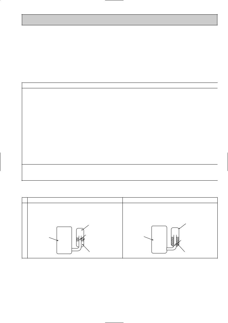
Compressor
|
New Specification |
Current Specification |
|||||||||||||
The incompatible refrigeration oil easily separates from |
Since refrigerant and refrigeration oil are compatible each, |
||||||||||||||
refrigerant and is in the upper layer inside the suction muffler. |
refrigeration oil goes back to the compressor through the |
||||||||||||||
Raising position of the oil back hole enables to back the |
lower position oil back hole. |
||||||||||||||
refrigeration oil of the upper layer to flow back to the |
|
|
|
|
|
|
|
||||||||
compressor. |
|
|
|
|
|
|
Suction muffler |
|
|
|
|
|
|
Suction muffler |
|
|
|
|
|
|
|
|
|
|
|
|
|||||
|
|
|
|
|
|
|
Oil back hole |
|
|
|
|
|
|
|
|
Compressor |
|
|
|
|
|
|
Compressor |
|
|
||||||
|
|
|
|
|
|
|
|
Refrigeration oil |
|
|
|
|
|
|
Oil back hole |
|
|
|
|
|
|
|
|
|
|
|
|
|
|
||
|
|
|
|
|
|
|
|
||||||||
Refrigeration oil /Refrigerant
NOTE : The unit of pressure has been changed to MPa on the international system of units(SI unit system). The conversion factor is: 1(MPa [Gauge]) =10.2(kgf/f [Gauge])
3

Conversion chart of refrigerant temperature and pressure
(MPa [Gauge]) |
|
|
|
|
|
|
|
|
|
|
|
|
|||
|
4.0 |
|
|
|
|
|
|
|
|
|
|
|
|
|
|
|
3.5 |
|
|
|
|
|
|
|
|
|
|
|
|
|
|
pressure |
|
|
|
|
|
R410A |
|
|
|
|
|
|
|||
|
|
|
|
|
|
|
|
|
|
|
|||||
|
|
|
|
|
|
|
|
|
|
|
|
||||
3.0 |
|
|
|
|
|
R22 |
|
|
|
|
|
|
|||
|
|
|
|
|
|
|
|
|
|
|
|
||||
liquid |
2.5 |
|
|
|
|
|
|
|
|
|
|
|
|
|
|
|
|
|
|
|
|
|
|
|
|
|
|
|
|
||
|
|
|
|
|
|
|
|
|
|
|
|
|
|
||
2.0 |
|
|
|
|
|
|
|
|
|
|
|
|
|
NOTE : The unit of pressure has been changed to MPa on the |
|
|
|
|
|
|
|
|
|
|
|
|
|
|
|||
1.5 |
|
|
|
|
|
|
|
|
|
|
|
|
|
||
Saturated |
|
|
|
|
|
|
|
|
|
|
|
|
|
||
|
|
|
|
|
|
|
|
|
|
|
|
|
|
international system of units(SI unit system). |
|
|
|
|
|
|
|
|
|
|
|
|
|
|
|
|
|
|
1.0 |
|
|
|
|
|
|
|
|
|
|
|
|
|
The conversion factor is: 1(MPa [Gauge]) =10.2(kgf/f [Gauge]) |
|
|
|
|
|
|
|
|
|
|
|
|
|
|
||
|
0.5 |
|
|
|
|
|
|
|
|
|
|
|
|
|
|
|
|
|
|
|
|
|
|
|
|
|
|
|
|
|
|
|
|
|
|
|
|
|
|
|
|
|
|
|
|
|
|
|
0.0 |
|
|
|
|
|
|
|
|
|
|
|
|
|
|
|
|
|
|
|
|
|
|
|
|
|
|
|
|
|
|
|
-0.5 |
|
|
|
|
|
|
|
|
|
|
|
|
|
|
|
-30 -20 |
-10 0 10 20 30 40 50 60 (:) |
|||||||||||||
1.Tools dedicated for the air conditioner with R410A refrigerant
The following tools are required for R410A refrigerant. Some R22 tools can be substituted for R410A tools.
The diameter of the service port on the stop valve in outdoor unit has been changed to prevent any other refrigerant being charged into the unit. Cap size has been changed from 7/16 UNF with 20 threads to 1/2 UNF with 20 threads.
R410A tools |
Can R22 tools be used? |
Description |
|
|
|
R410A has high pressures beyond the measurement range of existing |
|
Gauge manifold |
No |
gauges. Port diameters have been changed to prevent any other refrigerant |
|
|
|
from being charged into the unit. |
|
|
|
|
|
Charge hose |
No |
Hose material and cap size have been changed to improve the pressure |
|
resistance. |
|||
|
|
||
Gas leak detector |
No |
Dedicated for HFC refrigerant. |
|
|
|
|
|
Torque wrench |
Yes |
6.35 mm and 9.52 mm |
|
Flare tool |
Yes |
Clamp bar hole has been enlarged to reinforce the spring strength in the tool. |
|
|
|
|
|
Flare gauge |
New |
Provided for flaring work (to be used with R22 flare tool). |
|
Vacuum pump |
New |
Provided to prevent the back flow of oil. This adapter enables you to use |
|
adapter |
vacuum pumps. |
||
|
|||
Electronic scale for |
New |
It is difficult to measure R410A with a charging cylinder because the |
|
refrigerant charging |
refrigerant bubbles due to high pressure and high-speed vaporization |
||
|
|||
|
|
|
No : Not Substitutable for R410A Yes : Substitutable for R410A
2.Refrigerant piping
1Specifications
Use the refrigerant pipes that meet the following specifications.
Pipe |
Outside diameter |
Wall |
Insulation material |
|
|
||||
mm |
thickness |
|||
|
|
|||
|
|
|
|
|
For liquid |
6.35 |
0.8 mm |
Heat resisting foam plastic |
|
|
|
|
|
|
For gas |
9.52 |
0.8 mm |
Specific gravity 0.045 Thickness 8 mm |
|
|
|
|
|
•Use a copper pipe or a copper-alloy seamless pipe with a thickness of 0.8 mm. Never use any pipe with a thickness less than 0.8mm, as the pressure resistance is insufficient.
4

2Flaring work and flare nut
Flaring work for R410A pipe differs from that for R22 pipe.
For details of flaring work, refer to Installation manual “FLARING WORK”.
Pipe diameter |
Dimension of flare nut |
|
mm |
R410A |
R22 |
6.35 |
17 |
17 |
9.52 |
22 |
22 |
3.Refrigerant oil
Apply the special refrigeration oil (accessories: packed with indoor unit) to the flare and the union seat surfaces.
4.Air purge
•Do not discharge the refrigerant into the atmosphere.
Take care not to discharge refrigerant into the atmosphere during installation, reinstallation, or repairs to the refrigerant circuit.
•Use the vacuum pump for air purging for the purpose of environmental protection.
5.Additional charge
For additional charging, charge the refrigerant from liquid phase of the gas cylinder.
If the refrigerant is charged from the gas phase, composition change may occur in the refrigerant inside the cylinder and the outdoor unit. In this case, ability of the refrigeration cycle decreases or normal operation can be impossible. However, charging the liquid refrigerant all at once may cause the compressor to be locked. Thus, charge the refrigerant slowly.
Indoor unit
Refrigerant gas cylinder operating valve
Union
|
Stop valve |
Liquid pipe |
|
Gas pipe |
Outdoor unit |
Service port
Gauge manifold valve (for R410A)
 Charge hose (for R410A)
Refrigerant gas cylinder for R410A with siphon
Refrigerant (liquid)
Electronic scale for refrigerant charging
5
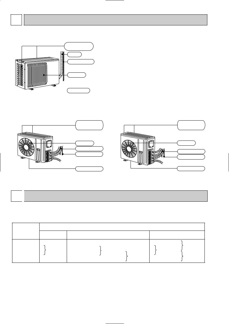
2 PART NAMES AND FUNCTIONS
MUX-2A28VB
Air inlet (back and side)
Piping
Drain hose
Air outlet
 Drain outlet
MUX-2A59VB MUX-3A63VB |
MUX-4A73VB |
|
MUX-3A60VB MUX-2A70VB |
|
|
Air inlet |
Air inlet |
|
(Back and side) |
(Back and side) |
|
Air outlet |
Air outlet |
|
Piping |
Piping |
|
Drainage hose |
||
Drainage hose |
||
|
||
Drain outlet |
Drain outlet |
3 
 INDOOR / OUTDOOR CORRESPONDENCE TABLE
MUX-2A28VB MUX-2A59VB MUX-3A60VB MUX-3A63VB MUX-2A70VB MUX-4A73VB
|
|
MUX-2A28VB |
|
Combination of |
A: |
MSC-CA20VB |
|
|
|
||
the connectable |
B: |
or |
|
indoor units |
MSC-GA20VB |
||
|
|
|
OUTDOOR UNIT |
|||
MUX-2A59VB |
|
MUX-3A60VB |
|
MUX-3A63VB |
|
|
|
||||
A: MSC-CA35VB |
|
|
A: MSC-CA35VB |
||
or |
A: |
MSC-CA25VB |
|
or |
|
MSC-GA35VB |
|
MSC-GA35VB |
|||
B: |
or |
|
|||
|
|
||||
B: MSC-CA20VB |
B: |
MSC-CA20VB |
|||
C: |
MSC-GA25VB |
||||
or |
|
or |
|||
|
|
|
|||
MSC-GA20VB |
|
|
C: MSC-GA20VB |
||
|
|
|
|||
|
|
|
|
|
|
MUX-2A70VB |
MUX-4A73VB |
||
|
|
A: MSC-CA35VB |
|
A: |
MSC-CA35VB |
or |
|
|
or |
B: MSC-GA35VB |
|
B: |
C: MSC-CA25VB |
||
MSC-GA35VB |
|||
|
|
or |
|
|
|
D: MSC-GA25VB |
|
|
|
|
|
6
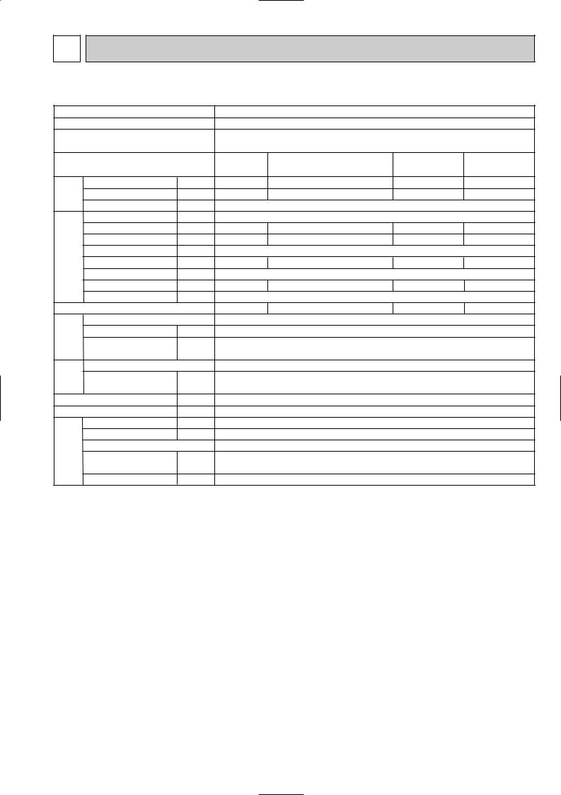
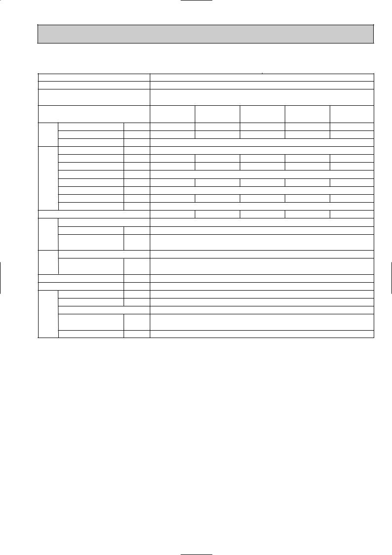
4 SPECIFICATION
NOTE: As for specification of the indoor units, refer to indoor unit service manual.
Outdoor model
Function
Outdoor unit power supply
Indoor unit No.
Capacity |
Outdoor air flow |
K /h |
|
|
Capacity |
kW |
|
|
Dehumidification |
R/h |
|
|
Power outlet |
A |
|
|
Running current |
A |
|
Electrical data |
Power input |
W |
|
Auxiliary heater |
A(kW) |
||
|
|||
|
Power factor |
% |
|
|
Starting current |
A |
|
|
Compressor motor current |
A |
|
|
Fan motor current |
A |
|
Coefficient of performance (C.O.P) |
|||
Compressor |
Model |
|
|
Output |
W |
||
|
|||
|
Winding |
" |
|
|
resistance (at 20:) |
||
|
|
||
Fan motor |
Model |
|
|
Winding |
" |
||
|
|||
|
resistance (at 20:) |
||
|
|
||
|
Dimensions WOHOD |
mm |
|
|
Weight |
kg |
|
|
Sound level |
dB |
|
Special remarks |
Fan speed |
rpm |
|
Fan speed regulator |
kg |
||
|
|
||
|
Refrigerant filling |
|
|
|
capacity (R410A) |
|
|
|
Refrigeration oil (Model) |
cc |
|
MUX-2A28VB |
|
MUX-2A59VB |
|
|
|
Cooling |
|
Cooling |
|
Single phase |
|
Single phase |
|
|
230V,50Hz |
|
230V,50Hz |
|
|
Single |
Double |
Single |
Single |
Double |
A or B |
A+B |
A |
B |
A+B |
2.4 |
1.4O2 |
3.5 |
2.4 |
3.5+2.4 |
0.9 |
0.2O2 |
1.4 |
0.9 |
1.4+0.9 |
|
1,914 |
|
2,460 |
|
|
10 |
|
20 |
|
3.20 |
3.25 |
5.73 |
3.51 |
8.96 |
725 |
730 |
1,280 |
785 |
2,005 |
|
— |
|
— |
|
98.5 |
97.7 |
97.1 |
97.2 |
97.3 |
|
21 |
|
48 |
|
2.91 |
2.96 |
5.16 |
2.94 |
8.39 |
|
0.29 |
|
0.57 |
|
3.16 |
3.50 |
2.65 |
2.93 |
2.84 |
RN092VHSHT |
MC1 : RN145VHSHT, MC2 : RN092VHSHT |
|||
|
600 |
|
MC1 : 1,000, MC2 : 600 |
|
C-R 3.87 |
MC1 : C-R 2.43 , MC2 : C-R 3.87 |
|||
C-S 6.14 |
|
C-S 3.80 |
C-S 6.14 |
|
RA6V33-FC |
|
RA6V60-GA |
|
|
WHT-BLK 223 |
|
WHT-BLK 90 |
|
|
BLK-RED 221 |
|
BLK-RED 146 |
|
|
780O540O255 |
|
840O640O330 |
|
|
|
35 |
|
66 |
|
|
49 |
|
52 |
|
|
825 |
|
730 |
|
|
1 |
|
1 |
|
0.90 (Room A+B) |
|
1.00 (Room A) |
|
|
|
0.80 (Room B) |
|
||
|
|
|
|
|
350 (NEO22) |
MC1 : 620 (NEO22), MC2 : 350 (NEO22) |
|||
|
|
|
|
|
NOTE: Test conditions are based on ISO 5151. Cooling : Indoor DB27°C WB19°C
Outdoor DB35°C WB24°C Indoor-Outdoor piping length : 5m
7
NOTE: As for specification of the indoor units, refer to indoor unit service manual.
Outdoor model
Function
Outdoor unit power supply
Indoor unit No.
Capacity |
Outdoor air flow |
K /h |
|
|
Capacity |
kW |
|
|
Dehumidification |
R/h |
|
|
Power outlet |
A |
|
|
Running current |
A |
|
Electrical data |
Power input |
W |
|
Auxiliary heater |
A(kW) |
||
|
|||
|
Power factor |
% |
|
|
Starting current |
A |
|
|
Compressor motor current |
A |
|
|
Fan motor current |
A |
|
Coefficient of performance (C.O.P) |
|||
Compressor |
Model |
" |
|
Output |
|||
|
W |
||
|
Winding |
|
|
|
resistance (at 20:) |
|
|
Fan motor |
Model |
|
|
Winding |
" |
||
|
|||
|
resistance (at 20:) |
||
|
|
||
|
Dimensions WOHOD |
mm |
|
|
Weight |
kg |
|
|
Sound level |
dB |
|
Special remarks |
Fan speed |
rpm |
|
Fan speed regulator |
kg |
||
|
|
||
|
Refrigerant filling |
|
|
|
capacity (R410A) |
|
|
|
Refrigeration oil (Model) |
cc |
|
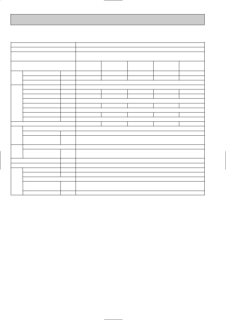
MUX-3A60VB
Cooling
Single phase 230V,50Hz
Single |
Single |
Double |
Double |
Triple |
A |
B or C |
A+B or A+C |
B+C |
A+B+C |
2.6 |
2.9 |
2.6+2.8 |
1.75O2 |
2.5+1.75O2 |
0.9 |
1.2 |
0.9+1.1 |
0.3O2 |
0.8+0.3O2 |
|
|
2,460 |
|
|
|
|
20 |
|
|
3.64 |
4.86 |
8.18 |
4.86 |
8.41 |
815 |
1,075 |
1,850 |
1,090 |
1,885 |
|
|
— |
|
|
97.3 |
96.2 |
98.3 |
97.5 |
97.5 |
|
|
47 |
|
|
3.07 |
4.29 |
7.61 |
4.29 |
7.84 |
|
|
0.57 |
|
|
3.06 |
2.61 |
2.81 |
3.02 |
3.02 |
MC1 : RN099VHSHT, MC2 : RN125VHSHT
MC1 : 650, MC2 : 800
MC1 : C-R 3.40 , MC2 : C-R 2.86
C-S 4.56 C-S 5.72
RA6V60-GA
WHT-BLK 90
BLK-RED 146
840O640O330
65
52
730
1
0.80(Room A)
1.00(Room B+C)
MC1 : 350 (NEO22), MC2 : 350 (NEO22)
NOTE: Test conditions are based on ISO 5151. Cooling : Indoor DB27°C WB19°C
Outdoor DB35°C WB24°C Indoor-Outdoor piping length : 5m
8
NOTE: As for specification of the indoor units, refer to indoor unit service manual.
Outdoor model
Function
Outdoor unit power supply
Indoor unit No.
Capacity |
Outdoor air flow |
K /h |
|
|
Capacity |
kW |
|
|
Dehumidification |
R/h |
|
|
Power outlet |
A |
|
|
Running current |
A |
|
Electrical data |
Power input |
W |
|
Auxiliary heater |
A(kW) |
||
|
|||
|
Power factor |
% |
|
|
Starting current |
A |
|
|
Compressor motor current |
A |
|
|
Fan motor current |
A |
|
Coefficient of performance (C.O.P) |
|||
Compressor |
Model |
" |
|
Output |
|||
|
W |
||
|
Winding |
|
|
|
resistance (at 20:) |
|
|
Fan motor |
Model |
|
|
Winding |
" |
||
|
|||
|
resistance (at 20:) |
||
|
|
||
|
Dimensions WOHOD |
mm |
|
|
Weight |
kg |
|
|
Sound level |
dB |
|
|
Fan speed |
rpm |
|
Special remarks |
Fan speed regulator |
|
|
Refrigerant filling |
kg |
||
|
capacity (R410A) |
|
|
|
Refrigeration oil (Model) |
cc |
|
MUX-3A63VB
Cooling
Single phase 230V,50Hz
Single |
Single |
Double |
Double |
Triple |
A |
B or C |
A+B or A+C |
B+C |
A+B+C |
3.5 |
2.4 |
3.5+2.4 |
1.45O2 |
3.4+1.45O2 |
1.4 |
0.9 |
1.4+0.9 |
0.4 |
1.4+0.4 |
|
|
2,460 |
|
|
|
|
20 |
|
|
5.73 |
3.64 |
8.92 |
3.69 |
8.84 |
1,280 |
815 |
1,975 |
830 |
1,980 |
|
|
— |
|
|
97.1 |
97.3 |
96.3 |
97.8 |
97.4 |
|
|
48 |
|
|
5.02 |
2.99 |
8.01 |
2.99 |
8.01 |
|
|
0.57 |
|
|
2.65 |
2.82 |
2.88 |
3.22 |
3.01 |
|
MC1 : RN145VHSHT, MC2 : RN092VHSHT |
|
||
|
|
MC1 : 1,000, MC2 : 600 |
|
|
|
MC1 : C-R 2.43 , MC2 : C-R 3.87 |
|
||
|
|
C-S 3.80 |
C-S 0.14 |
|
RA6V60-GA
WHT-BLK 90
BLK-RED 146
840O640O330
67
52
730
1
0.85(Room A)
0.85(Room B+C)
MC1 : 620 (NEO22), MC2 : 350 (NEO22)
NOTE: Test conditions are based on ISO 5151. Cooling : Indoor DB27°C WB19°C
Outdoor DB35°C WB24°C Indoor-Outdoor piping length 5m
9

NOTE: As for specification of the indoor units, refer to indoor unit service manual.
Outdoor model
Function
Outdoor unit power supply
Indoor unit No.
Capacity |
Outdoor air flow |
K /h |
|
|
Capacity |
kW |
|
|
Dehumidification |
R/h |
|
|
Power outlet |
A |
|
|
Running current |
A |
|
Electrical data |
Power input |
W |
|
Auxiliary heater |
A(kW) |
||
|
|||
|
Power factor |
% |
|
|
Starting current |
A |
|
|
Compressor motor current |
A |
|
|
Fan motor current |
A |
|
Coefficient of performance (C.O.P) |
|||
Compressor |
Model |
|
|
Output |
W |
||
|
|||
|
Winding |
" |
|
|
resistance (at 20:) |
||
|
|
||
Fan motor |
Model |
" |
|
Winding |
|||
|
|
||
|
resistance (at 20:) |
|
|
|
Dimensions WOHOD |
mm |
|
|
Weight |
kg |
|
|
Sound level |
dB |
|
|
Fan speed |
rpm |
|
Special remarks |
Fan speed regulator |
|
|
Refrigerant filling |
kg |
||
|
|||
|
capacity (R410A) |
||
|
|
||
|
Refrigeration oil (Model) |
cc |
|
NOTE: Test conditions are based on ISO 5151. Cooling : Indoor DB27°C WB19°C
Outdoor DB35°C WB24°C Indoor-Outdoor piping length : 5m
MUX-2A70VB |
|
Cooling |
|
Single phase 230V,50Hz |
|
Single |
Double |
A or B |
A+B |
3.5 |
3.5O2 |
1.4 |
1.4O2 |
2,460 |
|
20 |
|
5.88 |
11.49 |
1,300 |
2,540 |
— |
|
96.1 |
96.1 |
54 |
|
5.31 |
10.92 |
0.57 |
|
2.61 |
2.67 |
MC1 : RN145VHSHT, MC2 : RN145VHSHT |
|
MC1 : 1,000, MC2 : 1,000 |
|
MC1 : C-R 2.43 , MC2 : C-R 2.43 |
|
C-S 3.80 |
C-S 3.80 |
RA6V60-GA |
|
WHT-BLK 90 |
|
BLK-RED 146 |
|
840O640O330 |
|
68 |
|
52 |
|
730 |
|
1 |
|
0.95 (Room A) |
|
0.95 (Room B)
MC1 : 620 (NEO22), MC2 : 620 (NEO22)
10
NOTE: As for specification of the indoor units, refer to indoor unit service manual.
Outdoor model
Function
Outdoor unit power supply
Indoor unit No.
Capacity |
Outdoor air flow |
K /h |
|
|
Capacity |
kW |
|
|
Dehumidification |
R/h |
|
|
Power outlet |
A |
|
|
Running current |
A |
|
Electrical data |
Power input |
W |
|
Auxiliary heater |
A(kW) |
||
|
|||
|
Power factor |
% |
|
|
Starting current |
A |
|
|
Compressor motor current |
A |
|
|
Fan motor current |
A |
|
Coefficient of performance (C.O.P) |
|||
Compressor |
Model |
|
|
Output |
W |
||
|
|||
|
Winding |
" |
|
|
resistance (at 20:) |
||
|
|
||
Fan motor |
Model |
" |
|
Winding |
|||
|
|
||
|
resistance (at 20:) |
|
|
|
Dimensions WOHOD |
mm |
|
|
Weight |
kg |
|
|
Sound level |
dB |
|
Special remarks |
Fan speed |
rpm |
|
Fan speed regulator |
|
||
|
|
||
|
Refrigerant filling |
kg |
|
|
capacity (R410A) |
||
|
|
||
|
Refrigeration oil (Model) |
cc |
|
MUX-4A73VB
Cooling
Single phase 230V,50Hz
Single |
Single |
Double |
Double |
Double |
Triple |
Triple |
Four |
|
A+C or A+D |
A+B+C |
A+C+D |
||||||
|
|
|
|
|
||||
A or B |
C or D |
A+B |
or |
C+D |
or |
or |
A+B+C+D |
|
|
|
|
B+C or B+D |
|
A+B+D |
B+C+D |
|
|
3.4 |
2.75 |
1.95O2 |
3.4+2.7 |
1.7O2 |
1.95O2+2.8 3.4+1.7O2 1.95O2+1.7O2 |
|||
1.2 |
1.1 |
0.2O2 |
1.2+1.1 |
0.3O2 0.2O2+1.1 |
1.2+0.3O2 0.2O2+0.3O2 |
|||
|
|
|
2,760 |
|
|
|
||
|
|
|
20 |
|
|
|
|
|
5.28 |
4.54 |
5.46 |
9.57 |
4.78 |
9.61 |
9.66 |
9.75 |
|
1,180 |
1,015 |
1,210 |
2,095 |
1,060 |
2,105 |
2,140 |
2,210 |
|
|
|
|
— |
|
|
|
|
|
97.2 |
97.2 |
96.4 |
95.2 |
96.4 |
95.2 |
96.3 |
98.6 |
|
|
|
|
52 |
|
|
|
|
|
4.75 |
4.01 |
4.93 |
9.04 |
4.25 |
9.08 |
9.13 |
9.22 |
|
|
|
|
0.53 |
|
|
|
||
2.79 |
2.62 |
3.02 |
2.81 |
3.01 |
3.02 |
3.02 |
3.09 |
|
|
|
MC1 : RN145VHSHT, MC2 : RN125VHSHT |
|
|
||||
|
|
|
MC1 : 1,000, MC2 : 800 |
|
|
|||
|
|
MC1 : C-R 2.43 , MC2 : C-R 2.86 |
|
|
||||
|
|
|
C-S 3.80 |
C-S 5.72 |
|
|
||
RA6V60-FA
WHT-BLK 79
BLK-RED 80
840O850O330
76
52
730
1
1.05(Room A+B)
1.05(Room C+D)
MC1 : 620 (NEO22), MC2 : 350 (NEO22)
NOTE: Test conditions are based on ISO 5151. Cooling : Indoor DB27°C WB19°C
Outdoor DB35°C WB24°C Indoor-Outdoor piping length : 5m
11

5 NOISE CRITERIA CURVES
MUX-2A28VB |
|
|
FUNCTION |
SPL(dB(A)) |
LINE |
||||
|
|
|
|
|
|
||||
|
|
|
|
|
|
|
COOL |
49 |
|
|
|
|
|
|
Test conditions. |
|
|
||
|
90 |
|
|
|
|
Cooling : DB27: |
WB19: |
||
|
|
|
|
|
|
|
|
|
|
MICRO BAR |
80 |
|
|
|
|
|
|
|
|
70 |
|
|
|
|
|
|
|
|
|
dB re 0.0002 |
|
|
|
|
|
|
|
|
|
|
|
|
|
|
|
|
|
NC-70 |
|
60 |
|
|
|
|
|
|
|
|
|
LEVEL, |
|
|
|
|
|
|
|
|
NC-60 |
|
|
|
|
|
|
|
|
|
|
PRESSURE |
50 |
|
|
|
|
|
|
|
|
|
|
|
|
|
|
|
|
NC-50 |
|
|
|
|
|
|
|
|
|
|
|
BAND SOUND |
40 |
|
|
|
|
|
|
|
|
|
|
|
|
|
|
|
|
NC-40 |
|
30 |
|
|
|
|
|
|
|
|
|
OCTAVE |
|
|
|
|
|
|
|
|
|
|
|
|
|
|
|
|
|
NC-30 |
|
|
|
|
|
|
|
|
|
|
|
|
20 |
APPROXIMATE |
|
|
|
|
|
|
|
|
|
TERESHOLD OF |
|
|
|
|
|
|
|
|
|
HEARING FOR |
|
|
|
|
|
NC-20 |
|
|
|
CONTINUOUS |
|
|
|
|
|
||
|
|
|
|
|
|
|
|
||
|
|
NOISE |
|
|
|
|
|
|
|
|
10 |
63 |
125 |
250 |
500 |
1000 |
2000 |
4000 |
8000 |
|
|
||||||||
BAND CENTER FREQUENCIES, Hz
MUX-4A73VB |
|
|
FUNCTION |
SPL(dB(A)) |
LINE |
||||
|
|
|
|
|
|
||||
|
|
|
|
|
|
|
COOL |
52 |
|
|
|
|
|
|
Test conditions. |
|
|
||
|
90 |
|
|
|
|
Cooling :DB35: |
WB24: |
||
|
|
|
|
|
|
|
|
|
|
MICRO BAR |
80 |
|
|
|
|
|
|
|
|
70 |
|
|
|
|
|
|
|
|
|
dB re 0.0002 |
|
|
|
|
|
|
|
|
|
|
|
|
|
|
|
|
|
NC-70 |
|
60 |
|
|
|
|
|
|
|
|
|
LEVEL, |
|
|
|
|
|
|
|
|
NC-60 |
|
|
|
|
|
|
|
|
|
|
PRESSURE |
50 |
|
|
|
|
|
|
|
|
|
|
|
|
|
|
|
|
NC-50 |
|
|
|
|
|
|
|
|
|
|
|
BAND SOUND |
40 |
|
|
|
|
|
|
|
|
|
|
|
|
|
|
|
|
NC-40 |
|
30 |
|
|
|
|
|
|
|
|
|
OCTAVE |
|
|
|
|
|
|
|
|
|
|
|
|
|
|
|
|
|
NC-30 |
|
|
|
|
|
|
|
|
|
|
|
|
20 |
APPROXIMATE |
|
|
|
|
|
|
|
|
|
TERESHOLD OF |
|
|
|
|
|
|
|
|
|
HEARING FOR |
|
|
|
|
|
NC-20 |
|
|
|
CONTINUOUS |
|
|
|
|
|
||
|
|
|
|
|
|
|
|
||
|
|
NOISE |
|
|
|
|
|
|
|
|
10 |
63 |
125 |
250 |
500 |
1000 |
2000 |
4000 |
8000 |
|
|
||||||||
BAND CENTER FREQUENCIES, Hz
MUX-2A59VB |
|
|
FUNCTION |
SPL(dB(A)) |
LINE |
||||
|
|
|
|
|
|
||||
MUX-3A60VB |
|
|
|
COOL |
52 |
|
|||
|
|
|
|
|
|
||||
MUX-3A63VB |
|
|
|
|
|
|
|||
MUX-2A70VB |
|
|
|
|
|
|
|||
|
|
|
|
|
Test conditions. |
|
|||
|
90 |
|
|
|
|
Cooling :DB35: |
WB24: |
||
|
|
|
|
|
|
|
|
|
|
MICRO BAR |
80 |
|
|
|
|
|
|
|
|
70 |
|
|
|
|
|
|
|
|
|
dB re 0.0002 |
|
|
|
|
|
|
|
|
|
|
|
|
|
|
|
|
|
NC-70 |
|
60 |
|
|
|
|
|
|
|
|
|
LEVEL, |
|
|
|
|
|
|
|
|
NC-60 |
|
|
|
|
|
|
|
|
|
|
PRESSURE |
50 |
|
|
|
|
|
|
|
|
|
|
|
|
|
|
|
|
NC-50 |
|
|
|
|
|
|
|
|
|
|
|
BAND SOUND |
40 |
|
|
|
|
|
|
|
|
|
|
|
|
|
|
|
|
NC-40 |
|
30 |
|
|
|
|
|
|
|
|
|
OCTAVE |
|
|
|
|
|
|
|
|
|
|
|
|
|
|
|
|
|
NC-30 |
|
|
|
|
|
|
|
|
|
|
|
|
20 |
APPROXIMATE |
|
|
|
|
|
|
|
|
|
TERESHOLD OF |
|
|
|
|
|
|
|
|
|
HEARING FOR |
|
|
|
|
|
NC-20 |
|
|
|
CONTINUOUS |
|
|
|
|
|
||
|
|
|
|
|
|
|
|
||
|
|
NOISE |
|
|
|
|
|
|
|
|
10 |
63 |
125 |
250 |
500 |
1000 |
2000 |
4000 |
8000 |
|
|
||||||||
BAND CENTER FREQUENCIES, Hz
12

6 
 OUTLINES AND DIMENSIONS
MUX-2A28VB
|
Air in |
|
320 |
32 |
|
109 |
|
Air in |
|
Drainage |
147 110 |
3holes [33 |
Air out |
540
260 |
|
|
10 |
40 |
122 |
500
780
MUX-2A59VB
|
|
|
500 |
Drainage |
|
438 |
|
3holes {33 |
273 |
Air in |
|
|
|
||
|
|
|
30 |
125 |
34 |
|
|
|
Air in |
|
|
|
100 |
|
40 |
|
|
|
Air out |
840
121
320
330
61
640
65
80
REQUIRED SPACE more or100mm
100mm |
or |
|
|
|
more |
255 285 320 |
|
|
|
|
ore |
m |
or |
m |
|
||
|
|
|
400m |
|
|
25
Unit: mm
more
mor 100m
350mm |
or |
more |
|
||
|
|
Service panel
Liquid refrigerant
|
|
pipe joint |
|
|
|
Refrigerant pipe |
|
|
|
(flared) [6.35 |
|
226 176 126 76 |
|
- |
|
|
10 |
||
|
Gas refrigerant |
||
|
|
pipe joint |
|
|
120 |
Refrigerant pipe |
|
56 |
(flared) [9.52 |
||
|
Open as a rule 500mm or more if the front and both sides are open
100mm or more 100mm or more 200mm or more if
there are obstacles to both sides
360
Open as a rule
500mm or more if the back,
350mm or more
both sides and top are open
|
Service panel |
||
|
Liquid refrigerant |
||
|
pipe joint |
|
|
|
Refrigerant pipe |
||
|
(flared) {6.35 |
||
|
° |
|
Gas refrigerant |
|
|
|
|
° |
10 |
|
pipe joint |
10 |
} A UNIT |
505050 |
Refrigerant pipe |
|
(flared) {9.52 |
||
|
} B UNIT |
|
|
|
|
76 |
|
|
264 |
|
Gas refrigerant |
|
|
pipe joint |
|
Refrigerant pipe (flared) {9.52
13

MUX-3A60VB MUX-3A63VB
Drainage |
|
|
3 holes {33 |
273 |
|
|
|
|
125 |
34 |
|
|
Air in |
|
|
100 |
|
320
MUX-2A70VB
Drainage |
|
|
3 holes {33 |
273 |
|
|
|
|
125 |
34 |
|
|
Air in |
|
|
100 |
|
320
500
438
Air in
30
330 |
360 |
|
40 |
Air out |
|
840 |
61 |
121 |
|
|
|
° |
640 |
° |
10 |
10 |
|
|
|
|
65
Unit: mm
Open as a rule 500mm or more if the front and both sides are open
100mm or more 100mm or more 200mm or more if
there are obstacles on both sides
Open as a rule |
|
500mm or more if the back, |
350mm or more |
both sides and top are open |
|
Service panel Liquid refrigerant pipe joint Refrigerant pipe (flared) {6.35
} C UNIT 50
} A UNIT |
50 |
|
505050 |
||
} B UNIT |
|
|
|
76 |
|
|
Gas refrigerant |
|
264 |
pipe joint |
|
Refrigerant pipe |
||
|
||
|
(flared) {9.52 |
500
438
Air in
30
330 |
360 |
40
Air out
840 |
61 |
121 |
|
640 |
° |
|
|
|
10 |
80
Open as a rule 500mm or more if the front and both sides are open
100mm or more 100mm or more 200mm or more if
there are obstacles on both sides
Open as a rule
500mm or more if the back, 350mm or more both sides and top are open
|
Service panel |
|
Liquid refrigerant |
|
pipe joint |
° |
Refrigerant pipe |
(flared) {6.35 |
|
10 |
} A UNIT 505050 |
|
} B UNIT |
|
76 |
Gas refrigerant 264 pipe joint
Refrigerant pipe (flared) {9.52
14

MUX-4A73VB
Drainage |
438 |
|
40 |
|
273 |
|
|||
3 holes |
|
Air in |
||
{33 |
|
100 |
|
|
|
34 |
30 |
||
|
|
|
||
330 |
125 |
|
|
|
|
Air in |
|
|
|
|
|
|
Air out |
500 |
|
|
|
840 |
|
|
|
|
121 |
|
850
430
Unit: mm
|
|
Open as a rule |
|
|
500mm or more if |
|
|
the front and both |
|
|
sides are open |
|
|
100mm or more |
|
100mm or more |
200mm or more if |
|
there are obstacles |
|
|
|
on both sides |
360 |
|
|
65 |
Open as a rule |
|
500mm or more if the back, |
350mm or more |
|
61 |
both sides and top are open |
|
Service panel
|
|
Liquid refrigerant |
||
|
|
pipe joint |
||
|
|
Refrigerant pipe |
||
|
|
(flared) {6.35 |
||
10 |
10 |
|
|
|
° |
D Unit |
50 |
||
° |
|
|||
|
|
50 50 |
||
Gas refrigerant |
C Unit |
|||
|
50 50 |
|||
pipe joint |
|
B Unit |
||
Refrigerant pipe |
|
50 |
||
A Unit |
50 |
|||
(flared) {9.52 |
|
|||
|
|
|
76 |
|
80 Gas refrigerant |
260 |
|
||
pipe joint |
|
|
|
|
Refrigerant pipe |
|
|
||
(flared) {9.52 |
|
|
||
15
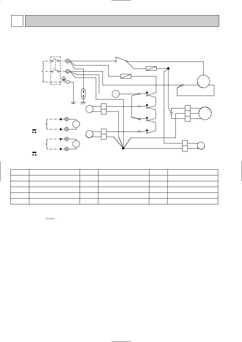
7 |
WIRING DIAGRAM |
|
|
|
|
|
|
|
|
|
|
|
||||
MUX-2A28VB |
|
|
|
|
|
|
|
|
|
|
|
|
|
|
|
|
POWER SUPPLY |
L TB1 |
|
BRN |
|
52C |
|
|
|
|
|
|
|
|
|
||
|
|
NO |
COM |
|
|
WHT |
|
|
|
|
||||||
|
~ / N |
|
|
|
|
|
|
|
WHT |
|
|
WHT 1 |
|
|
|
|
|
230V |
N |
|
|
|
|
|
|
|
|
|
|
|
|||
|
|
|
|
|
|
|
|
|
TB3 |
|
|
|
||||
|
50Hz |
|
|
|
|
|
|
F62 |
|
C |
|
|||||
|
|
|
|
|
|
BRN |
|
BRN |
|
|
||||||
|
|
|
|
|
|
|
|
|
|
|
||||||
|
|
|
|
|
|
|
|
|
|
|
|
|
|
|
||
|
|
|
PE |
BRN |
|
BLU |
F61 |
|
|
|
|
C1 RED S |
MC |
R |
||
|
|
|
|
|
|
|
|
|
||||||||
|
|
|
|
|
|
|
|
|
|
|||||||
|
|
|
|
|
|
|
|
|
|
|
||||||
|
CIRCUIT BREAKER |
DSAR |
|
|
|
BLU |
6 X1 |
2 |
BRN |
WHT |
|
|
|
|
||
|
|
|
|
|
BLU 252C1 |
5 X1 |
1 |
|
|
|
BLK |
|
||||
|
|
|
|
|
|
|
|
|
|
|
|
|||||
|
|
|
|
|
BLU |
|
|
|
3 |
|
|
|
|
|
|
|
|
|
|
|
|
BLU 2 BLU |
|
|
|
|
|
WHT |
WHT |
|
|||
TO INDOOR |
2 |
TB2 |
|
21R1BLU 1 BLU |
BLU |
|
4 |
BRN |
C2 |
BLU 1 |
BLK |
|
|
|||
WHT7 |
|
|
|
|
5 X2 1 |
RED 3 |
RED |
|
||||||||
|
|
|
|
|
|
|
|
|
|
|
|
|
2 |
|
MF |
|
UNIT No.A |
1 |
X1 |
|
|
|
|
|
|
3 |
BRN |
|
|
|
|
|
|
CONNECTING |
|
|
|
|
|
|
|
|
|
|
|
|||||
|
|
|
|
|
6 X2 2 |
|
|
|
|
|
||||||
|
12V |
2 |
BLK 8 |
|
BLU 2 BLU |
|
|
4 |
|
|
|
|
|
|
||
TO INDOOR |
YLW7 |
|
21R2BLU |
1 |
BLU |
|
|
|
|
|
|
|
|
|||
|
|
|
|
|
|
|
|
|
WHT 2 BLU |
|
|
|||||
UNIT No.B |
1 |
X2 |
|
|
|
|
|
|
|
|
|
21R |
|
|||
CONNECTING |
ORN8 |
|
|
|
2 |
|
|
|
|
|
BLU 1 BLU |
|
||||
|
|
|
|
|
|
|
|
|
|
|
||||||
|
12V |
|
|
|
|
TB3 |
|
|
|
|
|
|
|
|
||
|
|
|
|
|
|
|
|
|
|
|
|
|
|
|||
|
|
|
|
|
|
|
|
|
|
|
|
|
|
|
|
|
SYMBOL |
NAME |
C1 |
COMPRESSOR CAPACITOR |
C2 |
OUTDOOR FAN CAPACITOR |
DSAR |
SURGE ABSORBER |
F61,F62 |
FUSE(2A) |
MC |
COMPRESSOR(INNER PROTECTOR) |
SYMBOL |
NAME |
SYMBOL |
NAME |
MF |
OUTDOOR FAN MOTOR(INNER FUSE) |
21R1 |
SOLENOID COIL(A) |
TB1,TB2,TB3 |
TERMINAL BLOCK |
21R2 |
SOLENOID COIL(B) |
X1 |
RELAY(A) |
52C |
COMPRESSOR CONTACTOR |
X2 |
RELAY(B) |
|
|
21R |
SOLENOID COIL |
|
|
NOTE:1. About the indoor side electric wiring refer to the indoor unit electric wiring diagram for servicing.
2.Use copper conductors only. (For field wiring)
3.Symbols below indicate.
/: Terminal block,  : Connector
16

MUX-2A59VB
MUX-2A70VB
POWER SUPPLY |
LTB1 |
BRN |
TB4 |
|
|
|
|
|
|
|
||
~/N |
2 |
|
|
|
|
|
|
|
|
|||
230V |
N |
BLU |
1 |
|
|
|
|
|
|
|
BLU |
|
50Hz |
|
|
|
|
|
|
|
|||||
|
PE |
BRN |
|
|
|
|
|
|
|
|
|
|
|
GRN/YLW |
DSAR |
|
3 2 1 |
CN90 OUTDOOR CONTROLBRN |
|
BRN |
|||||
|
|
|
|
|||||||||
CIRCUIT BREAKER |
|
|
|
BLU |
BRN |
|
|
|
|
|
|
|
|
|
|
|
|
|
|
|
|
|
|
||
TO INDOOR |
1 TB2 |
BLU |
|
|
|
|
|
P.C. BOARD |
|
X521 |
||
|
3 |
|
F61 |
|
|
|
|
X522 |
3 4 |
|||
UNIT A |
2 |
YLW |
|
CN71 |
|
|
|
|
||||
CONNECTING |
|
2 |
|
|
|
|
3 |
4 |
||||
12V |
|
|
|
1 |
|
|
|
|
|
|
|
|
|
|
|
|
|
|
|
|
|
|
|
|
|
TO INDOOR |
1 |
BLU |
|
3 |
|
|
|
NR61 |
|
|
X522 |
X521 |
|
CN73 |
|
|
|
|
|
|
|
||||
UNIT B |
|
|
|
SR861 |
|
|
|
T61 |
|
|
||
2 |
ORN |
|
2 |
|
|
|
|
|
||||
CONNECTING |
|
|
|
|
|
|
|
|
|
|||
|
1 |
|
|
|
|
|
|
|
|
|||
12V |
|
|
|
|
|
|
|
|
|
|
|
|
|
|
|
|
|
|
|
|
|
|
|
|
|
|
|
|
|
|
CN91 1 2 3 4 5 6 |
LD2 |
LD1 |
|
|
|||
|
|
|
|
|
|
|
|
|
||||
|
|
|
|
|
|
WHT |
BLK |
RED |
RED |
RED |
|
|
BLU
C1 RED
S
BLK R MC1 C
WHT
C2 RED
S
BLK R MC2 C
WHT
MF61 C61
SYMBOL |
NAME |
SYMBOL |
C1 |
COMPRESSOR CAPACITOR(MC1) |
MC1 |
C2 |
COMPRESSOR CAPACITOR(MC2) |
MC2 |
C61 |
OUTDOOR FAN CAPACITOR |
MF61 |
DSAR |
SURGE ABSORBER |
NR61 |
F61 |
FUSE(3.15A) |
SR861 |
NAME |
SYMBOL |
NAME |
COMPRESSOR(INNER PROTECTOR) |
TB1 |
TERMINAL BLOCK |
COMPRESSOR(INNER PROTECTOR) TB2~TB4 |
TERMINAL BLOCK |
|
OUTDOOR FAN MOTOR (INNER PROTECTOR) |
T61 |
TRANSFORMER |
SURGE ABSORBER |
X521 |
COMPRESSOR CONTACTOR(MC1) |
OUTDOOR FAN RELAY |
X522 |
COMPRESSOR CONTACTOR(MC2) |
NOTE:1. About the indoor side electric wiring refer to the indoor unit electric wiring diagram for servicing.
2.Use copper conductors only. (For field wiring)
3.Symbols below indicate.
/: Terminal block,  : Connector
17
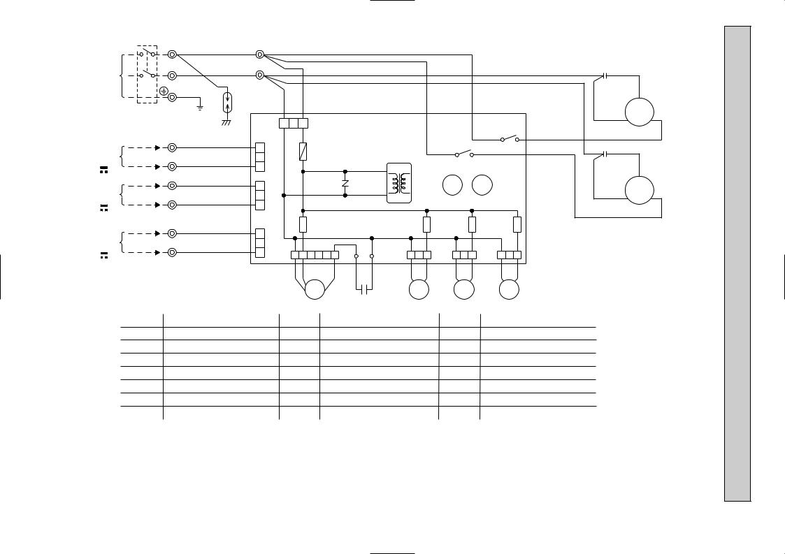
18
POWER SUPPLY |
L |
TB1 |
~/N |
|
|
230V |
N |
|
50Hz |
|
|
|
|
|
|
|
PE |
CIRCUIT BREAKER |
|
|
TO INDOOR |
1 |
TB2 |
UNIT A |
2 |
|
CONNECTING |
|
|
TO INDOOR |
1 |
|
UNIT B |
2 |
|
CONNECTING |
|
|
TO INDOOR |
1 |
TB3 |
UNIT C |
2 |
|
CONNECTING |
|
|
12V |
|
|
TB4 BRN 2
|
BLU 1 |
GRN/YLW |
BRN |
DSAR |
|
|
BLU |
|
YLW |
|
BLU |
|
ORN |
|
BLU |
|
WHT |
3
2
1
3
2
1
3
2
1
BLU |
BRN |
|
|
|
|
BRN |
3 2 1 CN90 OUTDOOR CONTROL P.C. BOARD |
||||||
CN71 |
F61 |
|
|
|
|
|
CN73 |
|
NR61 |
|
|
|
|
SR861 |
|
|
|
T61 |
|
|
CN74 |
|
|
|
|
||
|
|
|
|
SR863 |
||
CN91 1 2 |
|
LD2 |
LD1 |
CN81 |
||
3 4 5 6 |
1 |
2 3 |
||||
|
WHT BLK |
RED |
RED |
RED |
BLU |
BLU |
|
|
MF61 |
|
|
21RB |
|
C61
BLU
|
BRN |
|
|
X521 |
|
X522 |
3 |
4 |
3 |
4 |
|
X522 |
X521 |
|
|
SR866 |
|
|
SR865 |
|
CN85 |
CN86 |
||||
1 |
2 |
3 |
1 |
2 |
3 |
BLU |
BLU |
BLU |
BLU |
||
21R3 21R4
BLU
C1 RED
S
BLK R MC1 C
WHT
C2 RED
S
BLK R MC2 C
WHT
|
SYMBOL |
NAME |
|
SYMBOL |
NAME |
SYMBOL |
NAME |
||||||
|
C1 |
|
COMPRESSOR CAPACITOR(MC1) |
MF61 |
OUTDOOR FAN MOTOR(INNER PROTECTOR) |
TB2~TB4 |
TERMINAL BLOCK |
||||||
|
C2 |
|
COMPRESSOR CAPACITOR(MC2) |
NR61 |
SURGE ABSORBER |
T61 |
TRANSFORMER |
||||||
|
C61 |
OUTDOOR FAN CAPACITOR |
SR861 |
OUTDOOR FAN RELAY |
X521 |
COMPRESSOR CONTACTOR(MC1) |
|||||||
|
DSAR |
SURGE ABSORBER |
|
SR863 |
RELAY (21RB) |
X522 |
COMPRESSOR CONTACTOR(MC2) |
||||||
|
F61 |
|
FUSE(3.15A) |
|
SR865 |
RELAY (C) (21R4) |
21RB |
SOLENOID COIL |
|||||
|
MC1 |
COMPRESSOR(INNER PROTECTOR) |
SR866 |
RELAY (B) (21R3) |
21R3 |
SOLENOID COIL (B) |
|||||||
|
MC2 |
COMPRESSOR(INNER PROTECTOR) |
TB1 |
TERMINAL BLOCK |
21R4 |
SOLENOID COIL (C) |
|||||||
|
NOTE:1. About the indoor side electric wiring refer to the indoor unit electric wiring diagram for servicing. |
||||||||||||
|
|
2. Use copper conductors only. (For field wiring) |
|
|
|||||||||
12 12 |
|
3. Symbols below indicate. |
|
|
|
|
|||||||
|
/: Terminal block, |
|
|
|
|
|
: Connector |
|
|
|
|||
|
|
|
|
|
|
|
|
|
|
||||
3A60VB-MUX
VV

19
POWER SUPPLY |
L |
TB1 |
~/N |
|
|
230V |
N |
|
50Hz |
|
|
|
|
|
|
|
PE |
CIRCUIT BREAKER |
|
|
TO INDOOR |
1 |
TB2 |
UNIT A |
2 |
|
CONNECTING |
|
|
TO INDOOR |
1 |
|
UNIT B |
2 |
|
CONNECTING |
|
|
TO INDOOR |
1 |
TB3 |
UNIT C |
2 |
|
CONNECTING |
|
|
12V |
|
|
TB4 BRN 2
|
BLU 1 |
GRN/YLW |
BRN |
DSAR |
|
|
BLU |
|
YLW |
|
BLU |
|
ORN |
|
BLU |
|
WHT |
3
2
1
3
2
1
3
2
1
BLU |
BRN |
|
|
|
|
BRN |
3 2 1 CN90 OUTDOOR CONTROL P.C. BOARD |
||||||
CN71 |
F61 |
|
|
|
|
|
CN73 |
|
NR61 |
|
|
|
|
SR861 |
|
|
|
T61 |
|
|
CN74 |
|
|
|
|
||
|
|
|
|
SR863 |
||
CN91 1 2 |
|
LD2 |
LD1 |
CN81 |
||
3 4 5 6 |
1 |
2 3 |
||||
|
WHT BLK |
RED |
RED |
RED |
BLU |
BLU |
|
|
MF61 |
|
|
21RB |
|
C61
BLU
|
BRN |
|
|
X521 |
|
X522 |
3 |
4 |
3 |
4 |
|
X522 |
X521 |
|
|
SR866 |
|
|
SR865 |
|
CN85 |
CN86 |
||||
1 |
2 |
3 |
1 |
2 |
3 |
BLU |
BLU |
BLU |
BLU |
||
21R3 21R4
BLU
C1 RED
S
BLK R MC1 C
WHT
C2 RED
S
BLK R MC2 C
WHT
|
SYMBOL |
NAME |
|
SYMBOL |
NAME |
SYMBOL |
NAME |
||||||
|
C1 |
|
COMPRESSOR CAPACITOR(MC1) |
MF61 |
OUTDOOR FAN MOTOR(INNER PROTECTOR) |
TB2~TB4 |
TERMINAL BLOCK |
||||||
|
C2 |
|
COMPRESSOR CAPACITOR(MC2) |
NR61 |
SURGE ABSORBER |
T61 |
TRANSFORMER |
||||||
|
C61 |
OUTDOOR FAN CAPACITOR |
SR861 |
OUTDOOR FAN RELAY |
X521 |
COMPRESSOR CONTACTOR(MC1) |
|||||||
|
DSAR |
SURGE ABSORBER |
|
SR863 |
RELAY (21RB) |
X522 |
COMPRESSOR CONTACTOR(MC2) |
||||||
|
F61 |
|
FUSE(3.15A) |
|
SR865 |
RELAY (C) (21R4) |
21RB |
SOLENOID COIL |
|||||
|
MC1 |
COMPRESSOR(INNER PROTECTOR) |
SR866 |
RELAY (B) (21R3) |
21R3 |
SOLENOID COIL (B) |
|||||||
|
MC2 |
COMPRESSOR(INNER PROTECTOR) |
TB1 |
TERMINAL BLOCK |
21R4 |
SOLENOID COIL (C) |
|||||||
|
|
|
|
|
|
|
|||||||
12 12 |
NOTE:1. About the indoor side electric wiring refer to the indoor unit electric wiring diagram for servicing. |
||||||||||||
|
2. Use copper conductors only. (For field wiring) |
|
|
||||||||||
|
|
3. Symbols below indicate. |
|
|
|
|
|||||||
|
|
/: Terminal block, |
|
|
|
|
|
: Connector |
|
|
|
||
|
|
|
|
|
|
|
|
|
|
||||
3A63VB-MUX
VV

20
|
LTB1 |
|
POWER SUPPLY |
N |
|
~/N |
|
|
230V |
PE |
|
50Hz |
||
|
||
CIRCUIT BREAKER |
||
|
TB2 |
|
TO INDOOR |
1 |
|
|
||
UNIT D |
|
|
CONNECTING |
2 |
|
12V |
||
TO INDOOR |
1 |
|
|
||
UNIT C |
|
|
CONNECTING |
2 |
|
12V |
||
TO INDOOR |
1 TB3 |
|
|
||
UNIT B |
|
|
CONNECTING |
2 |
|
12V |
||
|
||
TO INDOOR |
1 |
|
|
||
UNIT A |
|
|
CONNECTING |
|
|
12V |
2 |
|
TB4
BRN 2
BLU 1
GRN/YLW |
BRN |
DSAR |
BLU
3
2 WHT 1
BLU
3
2 ORN 1
BLU
3
2 BRN 1
BLU
3
2
YLW
1
BLU |
BRN |
|
|
3 |
2 |
1 |
CN90 |
CN74 |
F61 |
|
|
CN73 |
|
|
|
CN72 |
SR861 |
|
|
CN71 |
|
|
|
CN91 1 2 3 4 5 6
WHT BLK |
RED |
MF61
NR61
LD2 |
LD1 |
RED |
RED |
|
C61 |
BRN
BRN
BLU |
|
|
|
|
|
|
|
|
|
|
|
|
|
|
|
|
|
RED |
BLU |
|
|
|
|
|
|
|
|
|
|
|
|
|
|
|
|
C1 |
S |
|
|
|
|
|
|
|
|
|
|
|
|
|
|
|
|
|
|
|
OUTDOOR CONTROL P.C. BOARD |
|
|
|
|
|
|
|
BLK |
R MC1 C |
|||||||||
|
|
|
|
|
|
|
|
|
||||||||||
|
|
|
|
|
|
|
|
|
|
|
|
|
|
X521 |
|
|
WHT |
|
|
|
|
|
|
|
|
|
|
|
|
|
|
|
|
|
|
|
|
|
|
|
|
|
|
|
|
|
|
X522 |
|
|
3 |
4 |
|
|
|
|
|
|
|
|
|
|
|
|
|
|
|
|
|
|
|
|
|
||
|
|
|
|
|
|
|
|
|
|
3 |
4 |
|
|
|
|
|
|
RED |
|
|
|
|
|
|
|
|
|
|
|
|
|
|
|
|
|
C2 |
S |
|
|
|
|
|
|
|
|
|
|
X522 |
|
|
X521 |
|
|
|||
|
|
|
|
|
|
|
|
|
|
|
|
|
|
|
||||
|
|
|
T61 |
|
|
|
|
|
|
|
|
|
|
|
|
|
BLK |
R MC2 C |
|
|
|
|
|
|
|
|
|
|
|
|
|
|
|
|
|
|
|
|
|
|
|
|
|
|
|
|
|
|
|
|
|
|
|
|
|
WHT |
|
SR868 |
|
|
SR867 |
|
|
SR866 |
|
|
SR865 |
|
|
|
SR864 |
|
SR863 |
|
|
|
CN83 |
|
|
CN84 |
|
|
CN85 |
|
|
CN86 |
|
|
CN82 |
|
CN81 |
|
|
|
1 |
2 |
3 |
1 |
2 |
3 |
1 |
2 |
3 |
1 |
2 |
3 |
1 |
2 |
3 |
1 |
2 |
3 |
|
BLU |
BLU |
|
BLU |
BLU |
|
BLU |
BLU |
|
BLU |
BLU |
|
BLU |
|
BLU |
BLU |
BLU |
|
|
|
21R1 |
|
|
21R2 |
|
|
21R3 |
|
|
21R4 |
|
|
21RA |
|
21RB |
|
|
|
SYMBOL |
NAME |
SYMBOL |
NAME |
SYMBOL |
NAME |
C1 |
COMPRESSOR CAPACITOR(MC1) |
SR861 |
OUTDOOR FAN RELAY |
X521 |
COMPRESSOR CONTACTOR(MC1) |
C2 |
COMPRESSOR CAPACITOR(MC2) |
SR863 |
RELAY (21RB) |
X522 |
COMPRESSOR CONTACTOR(MC2) |
C61 |
OUTDOOR FAN CAPACITOR |
SR864 |
RELAY (21RA) |
21RA |
SOLENOID COIL (BALANCE) |
DSAR |
SURGE ABSORBER |
SR865 |
RELAY (D) (21R4) |
21RB |
SOLENOID COIL (BALANCE) |
F61 |
FUSE(3.15A) |
SR866 |
RELAY (C) (21R3) |
21R1 |
SOLENOID COIL (A) |
MC1 |
COMPRESSOR(INNER PROTECTOR) |
SR867 |
RELAY (B) (21R2) |
21R2 |
SOLENOID COIL (B) |
MC2 |
COMPRESSOR(INNER PROTECTOR) |
SR868 |
RELAY (A) (21R1) |
21R3 |
SOLENOID COIL (C) |
MF61 |
OUTDOOR FAN MOTOR(INNER PROTECTOR) TB1~TB4 |
TERMINAL BLOCK |
21R4 |
SOLENOID COIL (D) |
|
NR61 |
SURGE ABSORBER |
T61 |
TRANSFORMER |
|
|
NOTE:1. About the indoor side electric wiring refer to the indoor unit electric wiring diagram for servicing.
2.Use copper conductors only. (For field wiring)
3.Symbols below indicate.
/: Terminal block, |
: Connector |
4A73VB-MUX
8 
 REFRIGERANT SYSTEM DIAGRAM
Unit : mm
MUX-2A28VB
INDOOR UNIT |
OUTDOOR UNIT |
UNIT A
UNIT B
Room temperature
thermistor |
Refrigerant pipe |
Solenoid |
|
valve |
|
||
RT11 |
|
||
[9.52 |
|
||
Strainer 21R |
|
||
|
(With insulation) |
|
|
|
|
#100 |
|
Indoor |
Stop valve |
Capillary tube |
Muffler |
heat |
with service port |
[3.0 x [1.4 x 1000 |
|
exchanger |
|
|
|
|
Flared connection |
|
|
Indoor coil |
Solenoid valve |
Compressor |
|
21R1 |
|
||
thermistor |
|
|
|
|
|
|
|
RT12 |
|
|
|
|
|
|
|
Strainer |
Outdoor |
|
Refrigerant pipe |
Stop |
Capillary tube |
#100 |
|
Room |
[6.35 |
valve |
[3.0 x [1.4 x 400 |
|
heat |
(With insulation) |
|
|
Capillary tube |
exchanger |
|
temperature |
|
|
|
[3.0 x [1.6 x 900 |
|
|
|
|
|
||
thermistor |
Refrigerant pipe |
|
|
|
|
|
|
|
|
||
RT11 |
[9.52 |
|
|
|
|
|
(With insulation) |
|
|
|
|
Indoor |
|
Stop valve |
|
heat |
|
||
|
with service port |
||
exchanger |
|
||
Flared connection |
|
|
|
|
|
|
|
|
|
|
Solenoid valve |
|
|
|
21R2 |
Indoor coil |
|
|
|
thermistor |
Refrigerant pipe |
Stop |
Capillary tube |
RT12 |
[6.35 |
valve |
[3.0 x [1.4 x 400 |
(With insulation)
 Refrigerant flow in cooling
MAX. REFRIGERANT PIPING LENGTH & MAX. HEIGHT DIFFERENCE
Indoor unit A |
Indoor unit B |
Max. length difference 10m
Outdoor unit
MUX-2A28VB
Additional piping max. length 15m
ADDITIONAL REFRIGERANT CHARGE (R410A:g)
UNIT No. |
Outdoor unit |
|
|
|
|
|
|
Refrigerant piping length (one way) |
|
|
|
|
|
|
|||||||||
|
|
|
|
|
|
|
|
|
|
|
|
|
|
|
|
|
|
|
|
|
|||
precharged |
10 |
11 |
12 |
13 |
14 |
15 |
16 |
17 |
18 |
19 |
20 |
21 |
22 |
23 |
24 |
25 |
26 |
27 |
28 |
29 |
30 |
||
|
|||||||||||||||||||||||
|
|
m |
m |
m |
m |
m |
m |
m |
m |
m |
m |
m |
m |
m |
m |
m |
m |
m |
m |
m |
m |
m |
|
A unit + B unit |
900g |
0 |
10 |
20 |
30 |
40 |
50 |
60 |
70 |
80 |
90 |
100 |
110 |
120 |
130 |
140 |
150 |
160 |
170 |
180 |
190 |
200 |
|
PIPING PREPARATION
1 Table below shows the specifications of pipes commercially available.
UNIT No. |
Pipe |
Outside diameter |
Insulation |
Insulation material |
|
mm |
thickness |
||||
|
|
|
|||
A and B UNIT |
For liquid |
6.35 |
8 mm |
Heat resisting foam plastic |
|
|
|
|
|
||
For gas |
9.52 |
8 mm |
0.045 specific gravity |
||
|
|||||
|
|
|
|
|
2 Ensure that the 2 refrigerant pipes are well insulated to prevent condensation. 3 Refrigerant bending radius must be 10cm or more.
21
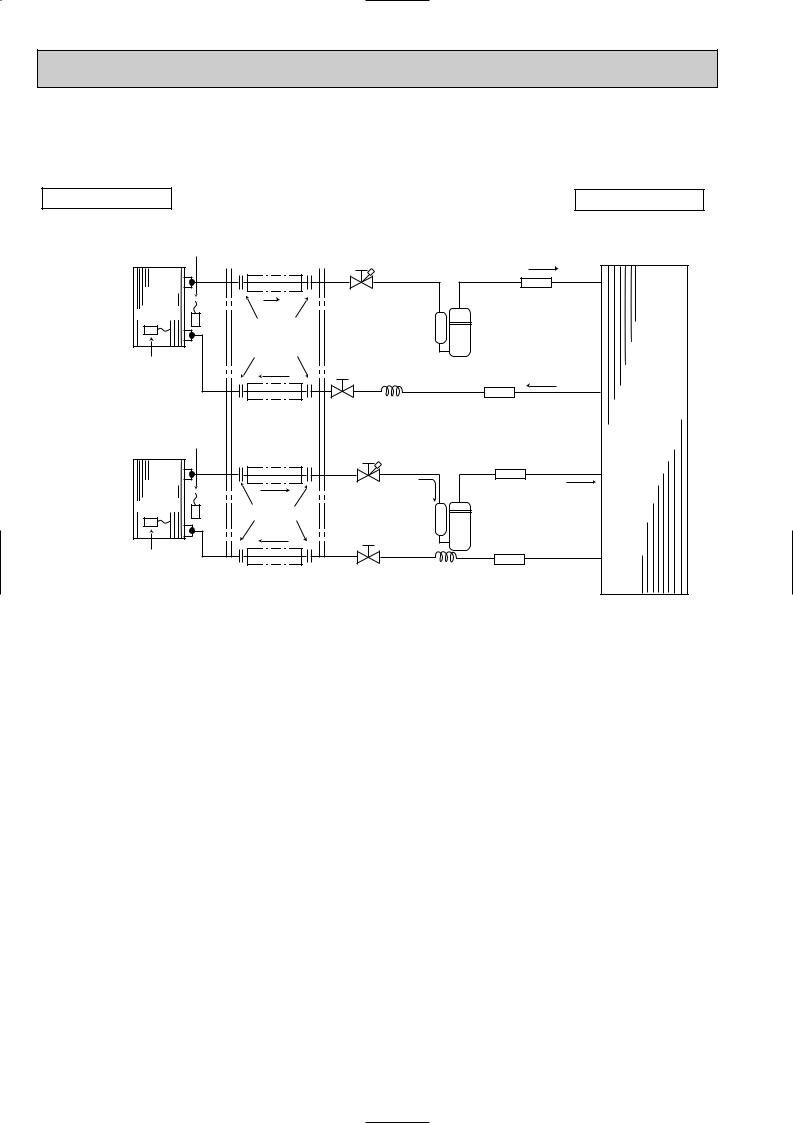
Unit : mm
MUX-2A59VB
INDOOR UNIT |
OUTDOOR UNIT |
UNIT A
UNIT B
Room temperature thermistor RT11
Indoor heat exchanger
Indoor coil |
thermistor |
RT12 |
Room |
temperature |
thermistor |
RT11 |
Indoor |
heat |
exchanger |
Indoor coil thermistor RT12
Refrigerant pipe [9.52
(With insulation)
|
Stop valve |
|
Muffler |
|
|
with service port |
|
|
|
Flared connection |
|
|
|
|
|
Stop valve |
Compressor(A) |
|
|
|
|
|
|
|
Refrigerant pipe |
Capillary tube |
Strainer |
Outdoor |
|
[6.35 |
[3.0 x [1.4 x 850 |
#100 |
||
(With insulation) |
|
|
|
heat |
|
|
|
|
|
Refrigerant pipe |
|
|
|
exchanger |
|
|
|
|
|
[9.52 |
|
|
|
|
(With insulation) |
|
|
Muffler |
|
|
Stop valve |
|
|
|
|
with |
|
|
|
Flared connection |
service port |
|
|
|
|
|
|
|
|
|
|
Compressor(B) |
|
|
Refrigerant pipe |
Stop valve |
Capillary tube |
Strainer |
|
[6.35 |
|
[3.0 x [1.4 x 1100 |
#100 |
|
(With insulation) |
|
|
|
|
 Refrigerant flow in cooling
22
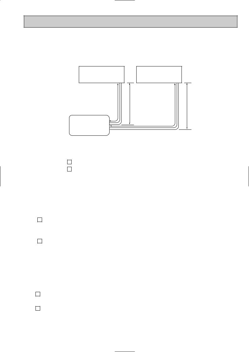
MAX.REFRIGERANT PIPING LENGTH & MAX. HEIGHT DIFFERENCE
Indoor unit A |
Indoor unit B |
LA |
H |
LB |
H |
Outdoor unit
MUX-2A59VB
|
UNIT No. |
|
Pipe length |
Height difference (H) |
No. of bends |
|
|
|
|
|
|
Max. |
A |
LA |
15m |
10m |
10 |
limits |
B |
LB |
15m |
10m |
10 |
|
|||||
|
|
|
|
|
|
ADDITIONAL REFRIGERANT CHARGE (R410A:g)
|
|
Outdoor unit |
|
|
Refrigerant piping length (one way) |
|
|
||||||||||
|
|
|
|
|
|
|
|
|
|
|
|
|
|
|
|
|
|
A |
unit |
precharged |
7m |
8m |
9m |
|
10m |
|
11m |
|
12m |
|
13m |
|
|
14m |
15m |
|
|
|
|
|
|
||||||||||||
|
|
|
|
|
|
|
|
|
|
|
|
|
|
|
|
|
|
|
|
1000g |
0 |
20 |
40 |
|
60 |
|
80 |
|
100 |
|
120 |
|
|
140 |
160 |
|
|
|
|
|
|
|
|
|
|
|
|
|
|||||
|
|
Outdoor unit |
|
|
Refrigerant piping length (one way,2 unit total) |
|
|
||||||||||
|
|
|
|
|
|
|
|
|
|
|
|
|
|
|
|
|
|
B |
unit |
precharged |
7m |
8m |
9m |
10m |
11m |
12m |
13m |
|
14m |
15m |
|||||
|
|
||||||||||||||||
|
|
|
|
|
|
|
|
|
|
|
|
|
|
|
|
|
|
|
|
800g |
0 |
20 |
40 |
|
60 |
|
80 |
|
100 |
|
120 |
|
|
140 |
160 |
|
|
|
|
|
|
|
|
|
|
|
|
|
|
|
|
|
|
PIPING PREPARATION
1Table below shows the specifications of pipes commercially available.
UNIT No. |
Pipe |
Outside diameter |
Insulation |
Insulation material |
|
|
|||||
mm |
thickness |
||||
|
|
|
|||
|
|
|
|
||
|
|
|
|
|
|
A unit |
For liquid |
6.35 |
8mm |
|
|
|
|
|
|
||
For gas |
9.52 |
8mm |
Heat resisting foam plastic |
||
|
|||||
|
|
|
|
||
B unit |
For liquid |
6.35 |
8mm |
0.045 specific gravity |
|
|
|||||
|
|
|
|
||
For gas |
9.52 |
8mm |
|
||
|
|
||||
|
|
|
|
|
2Ensure that the 2 refrigerant pipes are well insulated to prevent condensation. 3Refrigerant bending radius must be 10cm or more.
23

|
Unit : mm |
|
MUX-3A60VB |
INDOOR UNIT |
OUTDOOR UNIT |
Room |
|
temperature |
|
thermistor |
Refrigerant pipe |
RT11 |
[9.52 |
|
(With insulation) |
|
Indoor |
|
Stop valve |
|
|
Muffler |
|
|
UNIT A |
heat |
|
with service port |
|
|
|
|
|
exchanger |
|
|
|
|
|
|
|
|
|
|
Flared connection |
|
|
|
|
|
|
|
Indoor coil |
|
Stop valve |
Compressor(A) |
|
|
||
|
thermistor |
|
|
|
|
|
||
|
|
|
|
|
|
|
|
|
|
RT12 |
|
|
|
|
|
|
|
|
|
Refrigerant pipe |
|
Capillary tube |
Strainer |
|
Outdoor |
|
|
Room |
[6.35 |
|
[3.0 x [1.4 x 950 |
|
#100 |
|
|
|
(With insulation) |
|
|
|
|
|
heat |
|
|
temperature |
Stop valve |
|
|
|
|||
|
|
|
|
|
||||
|
|
|
|
Solenoid |
exchanger |
|||
|
thermistor |
Refrigerant pipe |
with |
|
|
|
||
|
RT11 |
[9.52 |
service port |
Strainer |
valve |
|
||
|
(With insulation) |
21RB |
Muffler |
|||||
|
|
|
|
|
|
#100 |
|
|
|
Indoor |
|
|
|
Capillary tube |
|
|
|
UNIT B |
heat |
|
|
|
[3.0 x [1.4 x 1000 |
|
|
|
exchanger |
Flared connection |
|
|
|
|
|
|
|
|
|
|
|
|
|
|
|
|
|
|
|
Stop |
Solenoid valve |
|
|
|
|
|
|
|
valve |
21R3 |
|
|
|
|
|
Indoor coil |
|
|
|
Compressor(B,C) |
|
||
|
|
|
|
|
|
|
|
|
|
thermistor |
Refrigerant pipe |
|
Capillary tube |
|
|
|
|
|
RT12 |
|
|
|
|
|
||
|
[6.35 |
|
[3.0 x [1.6 x 900 |
|
|
|
|
|
|
Room |
|
|
|
|
|
||
|
(With insulation) |
|
|
|
|
|
||
|
|
Capillary tube |
Strainer |
|
||||
|
temperature |
|
|
|
||||
|
|
|
[3.0 x [1.6 x 900 |
#100 |
|
|
||
|
thermistor |
Refrigerant pipe |
|
|
|
|||
|
|
|
|
|
||||
|
RT11 |
[9.52 |
|
|
|
|
|
|
|
|
(With insulation) |
|
|
|
|
|
|
|
Indoor |
|
Stop valve |
|
|
|
|
|
UNIT C |
heat |
|
with |
|
|
|
|
|
exchanger |
Flared connection |
service port |
|
|
Refrigerant flow in cooling |
|||
|
|
|
|
|
|
|
|
|
|
Stop |
Solenoid valve |
|
|
valve |
21R4 |
|
Indoor coil |
|
|
|
thermistor |
Refrigerant pipe |
Capillary tube |
|
RT12 |
|||
[6.35 |
[3.0 x [1.6 x 900 |
||
|
(With insulation) |
||
|
|
24
 Loading...