


SPLIT-TYPE,AIR CONDITIONERS
No. OB284
SERVICE MANUAL
Multi system type
Models
MUX-19TV - E1
MUX-20TV - E1
MUX-25TV - E1
MUX-19TV - E1 MUX-20TV - E1 MUX-25TV - E1
CONTENTS
1.TECHNICAL CHANGES ················
2.PART NAMES AND FUNCTIONS············
3.INDOOR/OUTDOOR
CORRESPONDENCE TABLE ··············
4.SPECIFICATION····················
5.NOISE CRITERIA CURVES ···············
6.OUTLINES AND DIMENSIONS ·············
7.WIRING DIAGRAM ··················
8.REFRIGERANT SYSTEM DIAGRAM ···········
9.PERFORMANCE CURVES ···············
10.TROUBLESHOOTING·················
11.DISASSEMBLY INSTRUCTIONS············
12.PARTS LIST······················
13.OPTIONAL PARTS···················
This manual describes technical data of outdoor unit.
For indoor unit refer to the service manuals No.OB227 REVISED EDITION-B and OB252 REVISED EDITION-A of corresponding models.
1 
 TECHNICAL CHANGES
MUX-19TV - E1
MUX-20TV - E1
MUX-25TV - E1
New models
2 
 PART NAMES AND FUNCTIONS
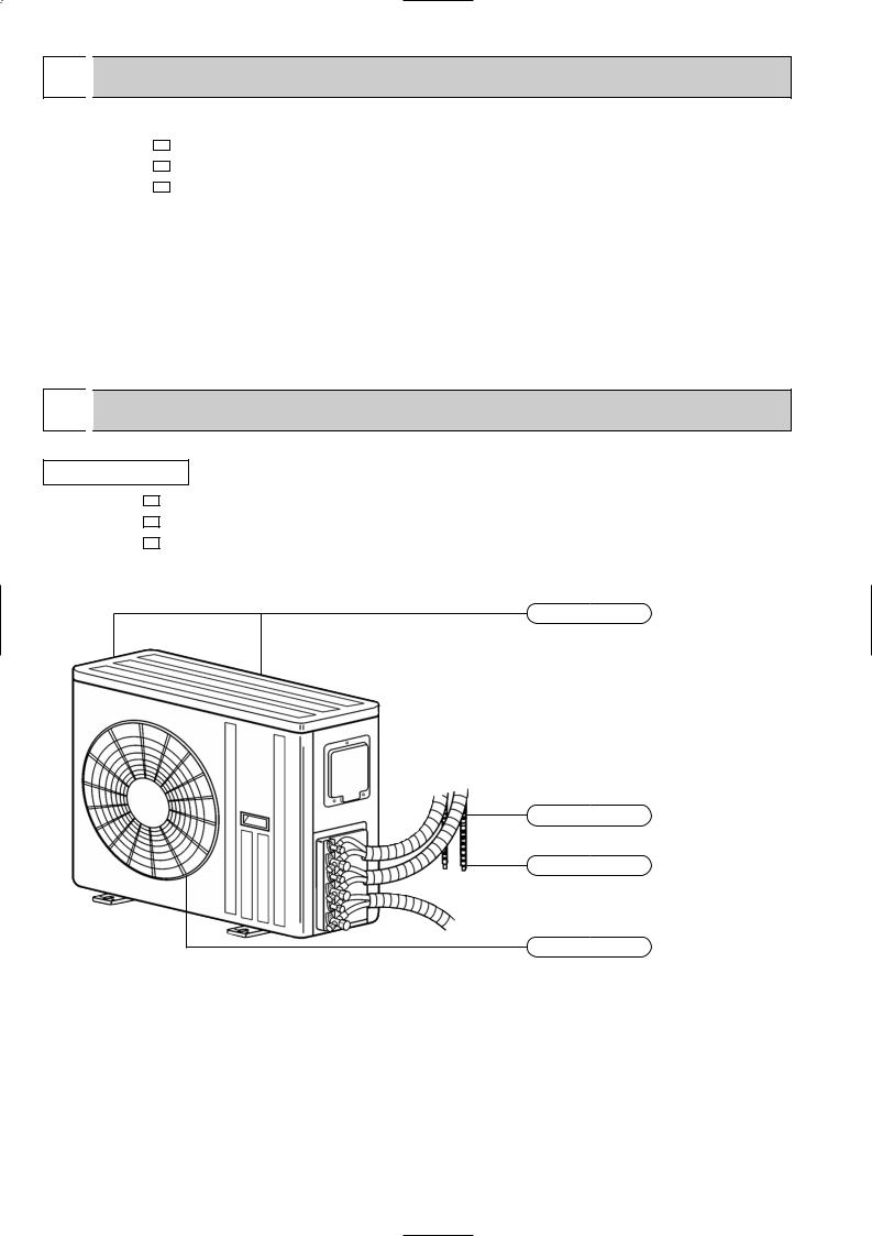
OUTDOOR UNIT
MUX-19TV - E1
MUX-20TV - E1
MUX-25TV - E1
Air inlet (Back and side)
Piping
Drainage hose
Air outlet
2
3 INDOOR / OUTDOOR CORRESPONDENCE TABLE
Combination of the connectable indoor units
OUTDOOR UNIT
MUX-19TV- E1 |
MUX-20TV- E1 |
MUX-25TV- E1 |
||||
A:07, |
B:12 |
A:09, |
B:09, |
C:09 |
A:12, |
B:12 |
|
|
|
|
|
|
|
There is no combination other than this table.
4 SPECIFICATION
Outdoor model
Outdoor unit power supply
Indoor unit No.
Capacity |
Outdoor air flow |
|
||
K /h |
||||
|
Capacity |
kW |
||
|
Dehumidification |
R/h |
||
|
Power outlet |
A |
|
|
|
Running current |
A |
|
|
Electrical data |
Power input |
W |
||
Auxiliary heater |
A(kW) |
|||
|
||||
|
Power factor |
% |
||
|
Starting current |
A |
|
|
|
Compressor motor current |
A |
|
|
|
Fan motor current |
A |
|
|
Coefficient of performance(C.O.P) |
||||
Compressor |
Model |
" |
||
Output |
||||
|
W |
|||
|
Winding |
|
|
|
|
resistance(at20:) |
|
||
Fan motor |
Model |
|
||
Winding |
" |
|
||
|
||||
|
resistance(at20:) |
|
||
|
|
|
||
|
Dimensions WOHOD |
mm |
||
|
Weight |
kg |
||
|
Sound level |
dB |
||
Special remarks |
Fan speed |
rpm |
||
Fan speed regulator |
kg |
|||
|
|
|
||
|
Refrigerant filling |
|
|
|
|
capacity(R22) |
|
|
|
|
Refrigerating oil (Model) |
cc |
||
NOTE: Test conditions are based on ISO 5151.
Cooling : Indoor |
DB27°C |
/ WB19°C |
Outdoor |
DB35°C |
/ WB(24°C) |
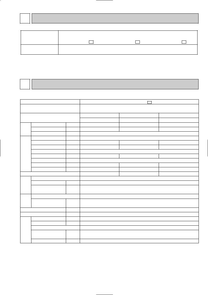
MUX-19TV - E1
Single phase 230V, 50Hz
Opetate 1 unit |
Opetate 1 unit |
Opetate 2 unit |
A |
B |
A+B |
3.5 |
2.2 |
3.5+2.2 |
1.6 |
0.8 |
1.6+0.8 |
|
Hi:2,460 / Lo:1,920 |
|
|
15 |
|
6.01 |
3.33 |
8.94 |
1,280 |
745 |
2,005 |
|
— |
|
92.6 |
97.3 |
97.5 |
|
45.6 |
|
5.68 |
3.00 |
8.37 |
0.33 |
0.33 |
0.57 |
2.65 |
2.82 |
2.74 |
RH220VHAT (Room A) / RH135VHAT (Room B)
1,050 / 650
C-R 2.13/4.18
C-S 3.91/5.76
RA6V60-DA
WHT-BLK 90 BKL-YLW 54
BLK-RED 146
840 640 330
63
52
High:730 / Low:580
2
Room A : 0.87
Room B :1.0
520(MS56) / 300(MS56)
3
|
|
|
|
|
|
|
|
|
|
|
|
|
|
|
|
|
|
|
|
|
|
|
|
|
|
|
|
|
Outdoor model |
|
|
|
|
|
|
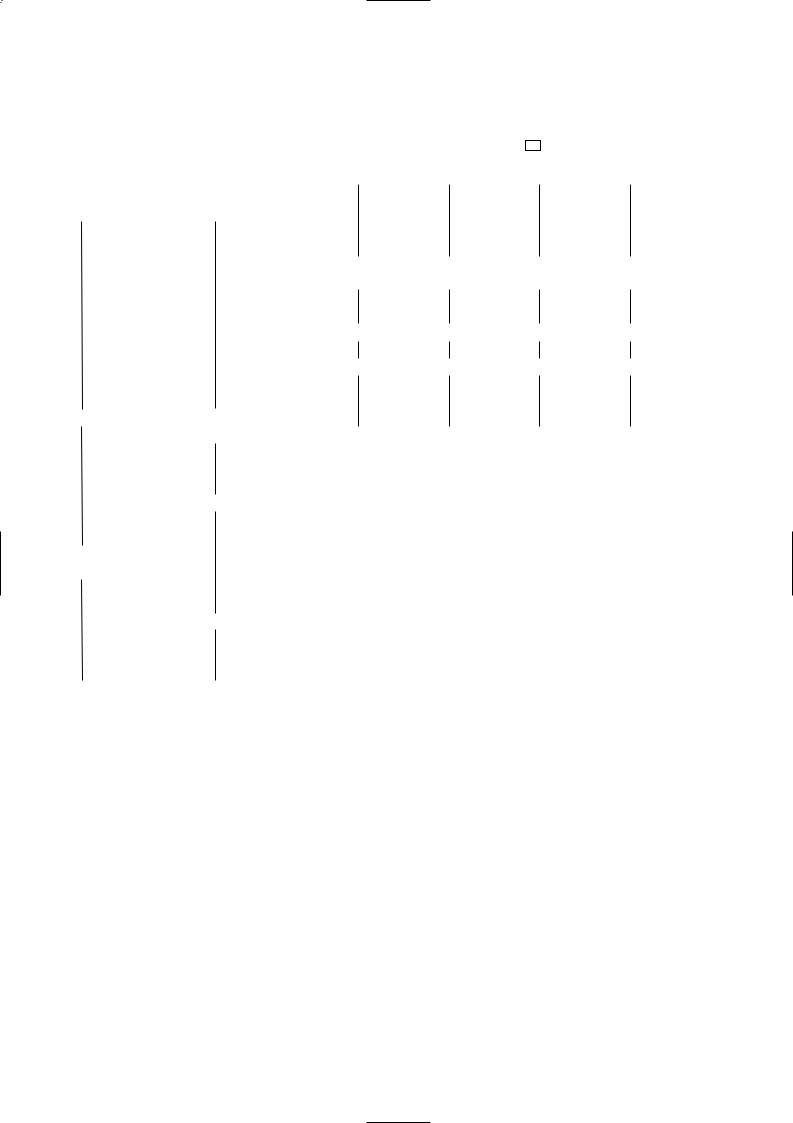
MUX-20TV - E1 |
|
|
|
|
|
Outdoor unit power supply |
|
|
|
|
Single phase |
|
|
||
|
|
|
|
|
|
|
|
|
|
230V, 50Hz |
|
|
|
|
|
Indoor unit No. |
|
|
Opetate 1 unit |
Opetate 1 unit |
Opetate 2 unit |
Opetate 2 unit |
Opetate 3 unit |
||
|
|
|
|
|
A |
B or C |
B+C |
A+B or A+C |
A+B+C |
|||
|
|
|
|
|
|
|||||||
Capacity |
Outdoor air flow |
|
K /h |
|
2.5 |
High: 2,460 / Low: 1,920 |
2.4+1.75 2 |
|||||
|
|
|
Capacity |
|
kW |
|
2.7 |
1.75 2 |
2.4+2.7 |
|||
|
|
|
Dehumidification |
|
R/h |
|
1.1 |
1.2 |
0.3 2 |
0.9+1.2 |
0.9+0.3 2 |
|
|
|
|
|
|
|
|
|
|
|
|
|
|
|
|
|
Power outlet |
|
A |
|
|
|
|
15 |
|
|
|
|
|
Running current |
|
A |
|
|
3.43 |
4.23 |
4.36 |
7.56 |
7.79 |
Electrical data |
|
Power input |
|
W |
|
775 |
965 |
1,000 |
1,740 |
1,785 |
||
|
Auxiliary heater |
|
A(kW) |
|
|
|
— |
|
|
|||
|
|
|
|
|
|
|
|
|
||||
|
|
|
Power factor |
|
% |
|
98.2 |
99.2 |
99.7 |
99.9 |
99.6 |
|
|
|
|
Starting current |
|
A |
|
|
|
|
40 |
|
|
|
|
|
Compressor motor current |
A |
|
|
3.10 |
3.90 |
4.03 |
6.99 |
7.22 |
|
|
|
|
Fan motor current |
|
A |
|
|
0.33 |
0.33 |
0.33 |
0.57 |
0.57 |
Coefficient of performance(C.O.P) |
|
3.09 |
2.70 |
3.27 |
2.82 |
3.12 |
||||||
Compressor |
Model |
|
|
|
|
|
RH140VHAT (Room A) / RH174VHAT (Room B,C) |
|
||||
|
|
|
|
|
|
|
|
|
||||
Output |
|
" |
|
|
|
700/800 |
|
|
||||
|
|
|
|
W |
|
|
|
|
|
|||
|
|
|
Winding |
|
|
|
|
|
|
C-R 4.03/3.30 |
|
|
|
|
|
resistance(at20:) |
|
|
|
|
|
C-S 5.71/5.80 |
|
|
|
Fan motor |
|
Model |
|
|
|
|
|
RA6V60-DA |
|
|
||
|
Winding |
|
" |
|
|
|
WHT-BLK 90 BLK-YLW 54 |
|
||||
|
|
|
|
|
|
|
||||||
|
|
|
resistance(at20:) |
|
|
|
|
|
BLK-RED 146 |
|
|
|
|
|
|
|
|
|
|
|
|
|
|
||
|
|
|
Dimensions WOHOD |
|
mm |
|
|
|
840 640 330 |
|
|
|
|
|
|
Weight |
|
kg |
|
|
|
62 |
|
|
|
|
|
|
Sound level |
|
dB |
|
|
|
52 |
|
|
|
|
|
|
Fan speed |
|
rpm |
|
|
High: 730 / Low: 580 |
|
|||
Special remarks |
|
|
Fan speed regulator |
|
|
|
|
|
|
2 |
|
|
|
|
|
|
|
|
|
|
|
|
|||
|
Refrigerant filling |
|
kg |
|
|
|
Room A : 0.8 |
|
|
|||
|
|
|
capacity(R22) |
|
|
|
|
|
|
Room B,C : 0.96 |
|
|
|
|
|
Refrigerating oil (Model) |
cc |
|
|
300(MS56) / 300(MS56) |
|
||||
NOTE: Test conditions are based on ISO 5151. |
|
|
|
|
|
|||||||
|
|
|
Cooling : Indoor |
DB27°C / WB19°C |
|
|
|
|
|
|||
|
|
|
Outdoor |
DB35°C / WB(24°C) |
|
|
|
|
||||
4
Outdoor model
Outdoor unit power supply
Indoor unit No.
Capacity |
Outdoor air flow |
|
||
K /h |
||||
|
Capacity |
kW |
||
|
Dehumidification |
R/h |
||
|
Power outlet |
A |
|
|
|
Running current |
A |
|
|
Electrical data |
Power input |
W |
||
Auxiliary heater |
A(kW) |
|||
|
||||
|
Power factor |
% |
||
|
Starting current |
A |
|
|
|
Compressor motor current |
A |
|
|
|
Fan motor current |
A |
|
|
Coefficient of performance(C.O.P) |
||||
Compressor |
Model |
" |
||
Output |
||||
|
W |
|||
|
Winding |
|
|
|
|
resistance(at20:) |
|
||
Fan motor |
Model |
|
||
Winding |
" |
|
||
|
||||
|
resistance(at20:) |
|
||
|
|
|
||
|
Dimensions WOHOD |
mm |
||
|
Weight |
kg |
||
|
Sound level |
dB |
||
Special remarks |
Fan speed |
rpm |
||
Fan speed regulator |
kg |
|||
|
|
|
||
|
Refrigerant filling |
|
|
|
|
capacity(R22) |
|
|
|
|
Refrigerating oil (Model) |
cc |
||
NOTE: Test conditions are based on ISO 5151.
Cooling : Indoor |
DB27°C |
/ WB19°C |
Outdoor |
DB35°C |
/ WB(24°C) |
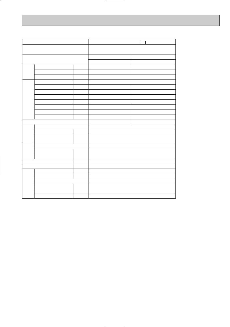
MUX-25TV - E1
Single phase 230V, 50Hz
Opetate 1 unit |
Opetate 2 unit |
A or B |
A+B |
3.5 |
3.5 2 |
1.6 |
1.6 2 |
High:2,760 / Low:1,920 |
|
|
25 |
6.11 |
12.42 |
1,350 |
2,760 |
|
— |
96.1 |
96.6 |
|
56 |
5.79 |
11.81 |
0.32 |
0.61 |
2.52 |
2.46 |
RH231VHAT 2
1,100 2
C-R 2.13
C-S 3.91
RA6V60-EA
WHT-BLK 67 BLK-YLW 75
BLK-RED 73
840 640 330
65
54
High: 810 / Low: 580
2
Room A: 0.9
Room B: 0.9
520(MS56) / 520(MS56)
5
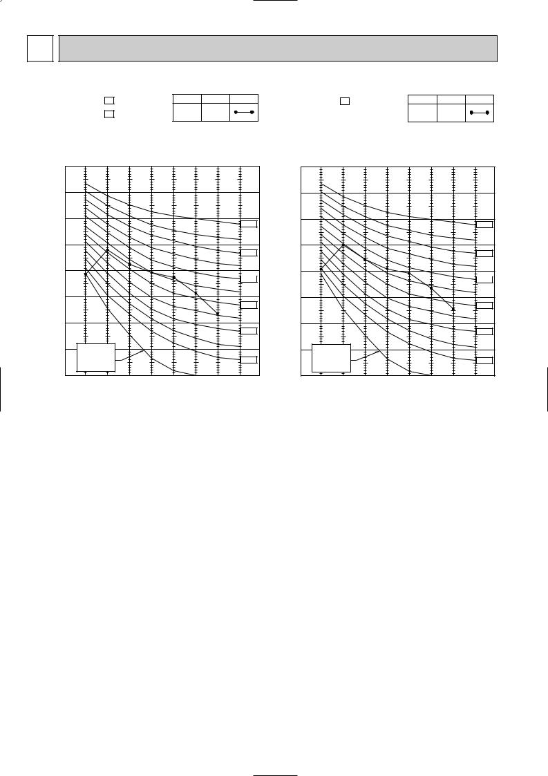
5 NOISE CRITERIA CURVES
MUX-19TV - E1 |
|
|
SPEED |
SPL(dB(A)) |
LINE |
||||
|
|
|
|
|
|
||||
MUX-20TV - E1 |
|
|
|
High |
52 |
|
|||
|
|
|
|
|
|
||||
|
|
|
|
|
Test conditions. |
|
|||
|
90 |
|
|
|
|
Cooling :DB35: WB24: |
|||
|
|
|
|
|
|
|
|
|
|
MICRO BAR |
80 |
|
|
|
|
|
|
|
|
70 |
|
|
|
|
|
|
|
|
|
dB re 0.002 |
|
|
|
|
|
|
|
|
NC-70 |
60 |
|
|
|
|
|
|
|
|
|
LEVEL, |
|
|
|
|
|
|
|
|
NC-60 |
|
|
|
|
|
|
|
|
|
|
PRESSURE |
50 |
|
|
|
|
|
|
|
|
|
|
|
|
|
|
|
|
NC-50 |
|
|
|
|
|
|
|
|
|
|
|
BAND SOUND |
40 |
|
|
|
|
|
|
|
|
|
|
|
|
|
|
|
|
NC-40 |
|
30 |
|
|
|
|
|
|
|
|
|
OCTAVE |
|
|
|
|
|
|
|
|
|
|
|
|
|
|
|
|
|
NC-30 |
|
|
|
|
|
|
|
|
|
|
|
|
20 |
APPROXIMATE |
|
|
|
|
|
|
|
|
|
TERESHOLD OF |
|
|
|
|
|
|
|
|
|
HEARING FOR |
|
|
|
|
|
NC-20 |
|
|
|
CONTINUOUS |
|
|
|
|
|
||
|
|
|
|
|
|
|
|
||
|
|
NOISE |
|
|
|
|
|
|
|
|
10 |
63 |
125 |
250 |
500 |
1000 |
2000 |
4000 |
8000 |
|
|
||||||||
BAND CENTER FREQUENCIES, Hz
MUX-25TV - E1 |
|
|
SPEED |
SPL(dB(A)) |
LINE |
||||
|
|
|
|
|
|
||||
|
|
|
|
|
|
|
High |
54 |
|
|
|
|
|
|
Test conditions. |
|
|
||
|
90 |
|
|
|
|
Cooling :DB35: WB24: |
|||
|
|
|
|
|
|
|
|
|
|
MICRO BAR |
80 |
|
|
|
|
|
|
|
|
70 |
|
|
|
|
|
|
|
|
|
dB re 0.002 |
|
|
|
|
|
|
|
|
NC-70 |
60 |
|
|
|
|
|
|
|
|
|
LEVEL, |
|
|
|
|
|
|
|
|
NC-60 |
|
|
|
|
|
|
|
|
|
|
PRESSURE |
50 |
|
|
|
|
|
|
|
|
|
|
|
|
|
|
|
|
NC-50 |
|
|
|
|
|
|
|
|
|
|
|
BAND SOUND |
40 |
|
|
|
|
|
|
|
|
|
|
|
|
|
|
|
|
NC-40 |
|
30 |
|
|
|
|
|
|
|
|
|
OCTAVE |
|
|
|
|
|
|
|
|
|
|
|
|
|
|
|
|
|
NC-30 |
|
|
|
|
|
|
|
|
|
|
|
|
20 |
APPROXIMATE |
|
|
|
|
|
|
|
|
|
TERESHOLD OF |
|
|
|
|
|
|
|
|
|
HEARING FOR |
|
|
|
|
|
NC-20 |
|
|
|
CONTINUOUS |
|
|
|
|
|
||
|
|
|
|
|
|
|
|
||
|
|
NOISE |
|
|
|
|
|
|
|
|
10 |
63 |
125 |
250 |
500 |
1000 |
2000 |
4000 |
8000 |
|
|
||||||||
BAND CENTER FREQUENCIES, Hz
6

6 
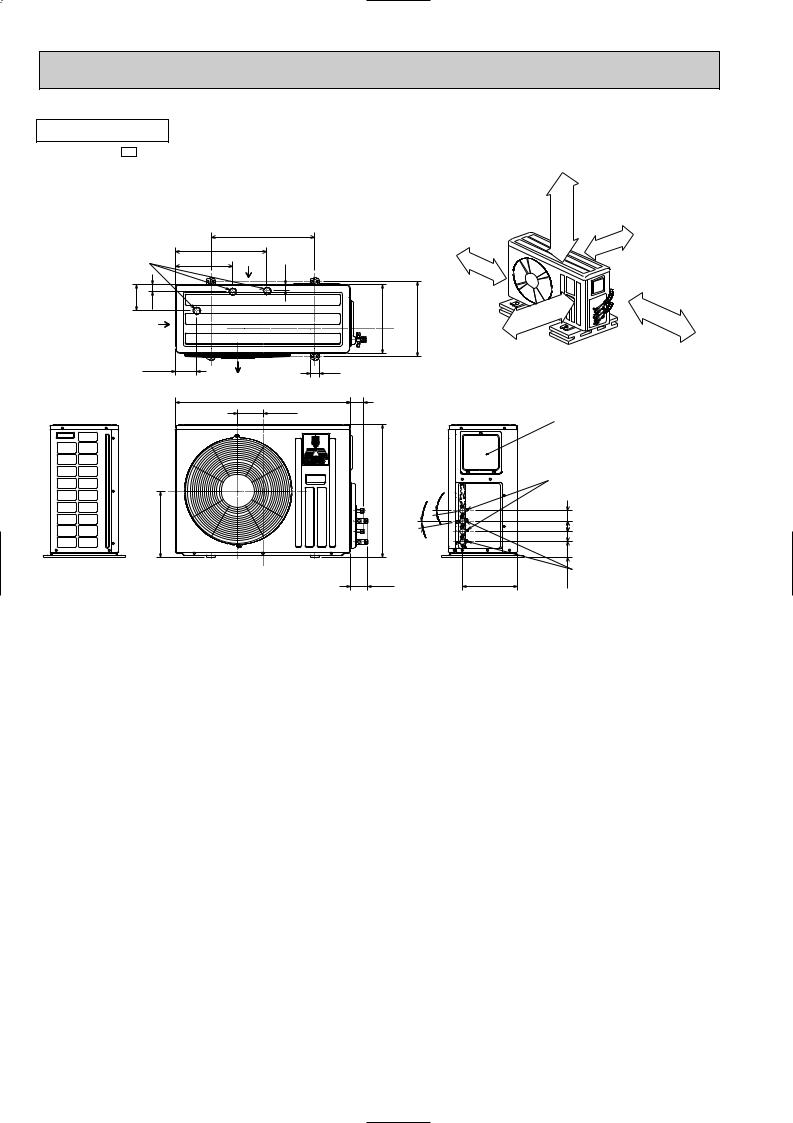
 OUTLINES AND DIMENSIONS
OUTDOOR UNIT |
Unit: mm |
|
|
MUX-19TV- E1 |
|
|
|
|
500 |
Drainage |
272.9 |
438.4 |
|
3hoies {33 |
|
Air in |
|
|
|
|
|
125.6 |
34 |
|
|
Air in |
|
100.3 |
40 |
|
|
|
Air out |
|
840 |
|
121.3 |
319.8
OUTDOOR UNIT
MUX-20TV- E1
|
|
|
500 |
Drainage |
272.9 |
438.4 |
|
3hoies {33 |
|
Air in |
|
|
|
|
|
125.6 |
34 |
|
|
Air in |
|
100.3 |
40 |
|
|
|
Air out |
|
840 |
|
121.3 |
319.8
Open as a rule 500mm or more if the front and both sides are open
100mm or more 100mm or more 200mm or more if
there are obstacles to both sides
330 |
360.6 |
Open as a rule |
|
|
|
|
|
|
|
|
|
500mm or more if the back, |
|
350mm or more |
|
|
both sides and top are open |
|
|
|
|
|
|
|
61.7 |
|
Service panel |
||
|
|
|||
|
|
Liquid refrigerant |
||
|
|
pipe joint |
|
|
|
|
Refrigerant pipe |
||
|
|
(flared) {6.35 |
||
640 |
|
° |
|
Gas refrigerant |
|
° |
10 |
|
pipe joint |
|
10 |
|
||
|
} B UNIT |
5050 |
Refrigerant pipe |
|
|
|
|||
|
|
(flared) {9.52 |
||
|
|
} A UNIT |
50 |
|
66.2 |
|
|
|
Gas refrigerant |
80.7 |
|
264.2 |
75.8 |
|
|
pipe joint |
|||
|
|
|||
|
|
|
||
Refrigerant pipe
(flared) {12.7
Unit: mm
330 |
360.6 |
61.7
|
|
° |
640 |
° |
10 |
10 |
|
|
|
|
Open as a rule 500mm or more if the front and both sides are open
100mm or more 100mm or more 200mm or more if
there are obstacles to both sides
Open as a rule
500mm or more if the back, 350mm or more both sides and top are open
Service panel Liquid refrigerant pipe joint Refrigerant pipe (flared) {6.35
} C UNIT 50
} A UNIT |
50 |
505050 |
|
} B UNIT |
|
66.2 |
75.8 |
Gas refrigerant |
pipe joint |
264.2
Refrigerant pipe (flared) {9.52
7
OUTDOOR UNIT |
Unit: mm |
|
|
MUX-25TV- E1 |
|
|
|
|
500 |
|
Drainage |
272.9 |
438.4 |
|
|
3hoies {33 |
|
Air in |
|
|
|
|
|
|
|
125.6 |
34 |
|
|
330 |
|
Air in |
|
|
|
|
100.3 |
|
|
40 |
|
|
|
|
|
|
|
|
Air out |
|
|
|
|
840 |
61.7 |
|
|
|
121.3 |
|
640
319.8
80.7
100mm or more
360.6
Open as a rule
500mm or more if the back, both sides and top are open
Open as a rule 500mm or more if the front and both sides are open
100mm or more 200mm or more if there are obstacles to both sides
350mm or more
|
|
Service panel |
|
|
|
Liquid refrigerant |
|
|
|
pipe joint |
|
|
° |
Refrigerant pipe |
|
|
(flared) {6.35 |
||
° |
10 |
|
|
10 |
|
} A UNIT 505050 |
|
|
|
} B UNIT |
|
|
|
75.8 |
Gas refrigerant |
|
264.2 |
pipe joint |
|
|
|
||
Refrigerant pipe (flared) {12.7
8
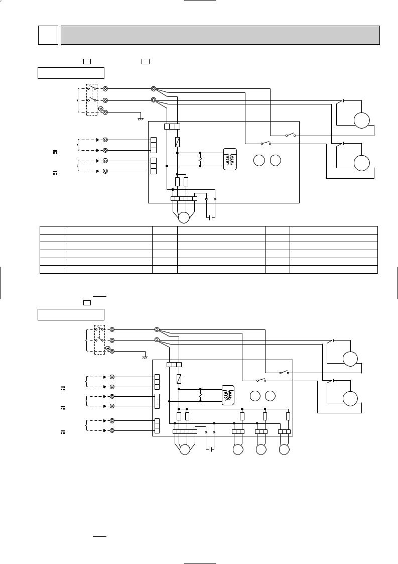
7 |
WIRING DIAGRAM |
|
|
|
||||||
MUX-19TV - E1 |
MUX-25TV - E1 |
|
|
|
|
|
|
|||
OUTDOOR UNIT MODELS WIRING DIAGRAM |
||||||||||
POWER SUPPLY |
L |
TB1 |
BRN |
2 TB4 |
|
|
|
|
||
~/N |
|
|
|
|
|
|
|
|
|
|
230V |
|
N |
|
BLU |
1 |
|
|
|
|
|
50Hz |
|
|
|
|
|
|
|
|||
|
|
|
PE |
GRN/YLW |
BLU |
BRN |
|
|
BRN |
|
CIRCUIT BREAKER |
|
|
|
|
|
|||||
|
|
|
|
|
|
|
|
|||
|
|
|
|
|
|
3 2 1 |
CN90 OUTDOOR CONTROL PC BOARD |
|||
TO INDOOR |
|
2 |
TB2 |
BLU |
3 |
CN71 |
F61 |
(3.15A) |
|
|
UNIT A |
|
|
|
|
|
|
|
|
|
|
|
1 |
|
|
2 |
|
|
|
|
|
|
CONNECTING |
|
YLW |
|
|
|
|
|
|||
12V |
|
|
|
1 |
|
|
|
|
|
|
|
2 |
|
|
|
|
|
|
|
||
TO INDOOR |
|
|
BLU |
3 |
CN73 |
|
NR61 |
|
|
|
UNIT B |
|
|
|
|
|
|
|
|||
|
1 |
|
|
2 |
|
|
|
|
||
CONNECTING |
|
ORN |
|
|
|
|
T61 |
|||
12V |
|
|
|
|
1 |
|
|
|
|
|
|
|
|
|
|
|
|
SR861 |
SR862 |
|
|
|
|
|
|
|
|
CN91 1 2 3 4 5 6 |
LD2 |
LD1 |
||
|
|
|
|
|
|
|
WHT YLW |
BLK RED |
RED |
RED |
|
|
|
|
|
|
|
|
|
|
C61 |
|
|
|
|
|
|
|
|
MF61 |
|
|
BLU
BRN |
|
BLU |
|
X521 |
|
X522 |
3 |
4 |
3 |
4 |
|
X522 |
X521 |
|
C1 RED
S
BLK R MC1 C
WHT
C2 RED
S
BLK R MC2 C
WHT
SYMBOL |
NAME |
SYMBOL |
NAME |
SYMBOL |
NAME |
C1 |
COMPRESSOR CAPACITOR (MC1) |
MC2 |
COMPRESSOR (INNER PROTECTOR) |
TB1 |
TERMINAL BLOCK |
C2 |
COMPRESSOR CAPACITOR (MC2) |
MF61 |
FAN MOTOR (INNER PROTECTOR) |
TB2~TB4 |
TERMINAL BLOCK |
C61 |
FAN MOTOR CAPACITOR |
NR61 |
SURGE ABSORBER |
T61 |
TRANSFORMER |
F61 |
FUSE (3.15A) |
SR861 |
FAN MOTOR RELAY |
X521 |
COMPRESSOR CONTACTOR (MC1) |
MC1 |
COMPRESSOR (INNER PROTECTOR) |
SR862 |
FAN MOTOR RELAY |
X522 |
COMPRESSOR CONTACTOR (MC2) |
NOTE:1. About the outdoor side electric wiring refer to the outdoor unit electric wiring diagram for servicing. |
|
VG79B082H01 |
|||
2.Use copper conductors only. (For field wiring)
3.Symbols below indicate.
/: Terminal block,  : Connector
MUX-20TV - E1
OUTDOOR UNIT MODEL WIRING DIAGRAM
POWER SUPPLY |
L |
TB1 |
BRN 2 TB4 |
|
|
|
|
|
|
|
||
~/N |
|
|
|
|
|
|
|
|
|
|
|
|
230V |
N |
|
BLU 1 |
|
|
|
|
|
|
|
|
|
50Hz |
|
|
BLU |
BRN |
|
|
|
|
|
BRN |
||
|
|
PE |
GRN/YLW |
|
|
|
|
|
||||
|
|
|
|
|
|
|
|
|
|
|||
CIRCUIT BREAKER |
|
|
|
|
|
|
|
|
|
|
||
|
|
|
|
|
3 2 1 |
CN90 OUTDOOR CONTROL PC BOARD |
||||||
CONNECTING |
2 |
TB2 |
YLW |
2 |
CN71 |
F61 |
(3.15A) |
|
|
|
|
|
1 |
|
|
|
|
|
|
||||||
TO INDOOR |
|
|
BLU |
3 |
|
|
|
|
|
|
|
|
UNIT A |
|
|
|
|
|
|
|
|
|
|
|
|
|
|
|
|
|
|
|
|
|
|
|
|
|
12V |
2 |
|
|
1 |
|
|
|
|
|
|
|
|
TO INDOOR |
|
BLU |
3 |
CN73 |
|
NR61 |
|
|
|
|
||
1 |
|
|
|
|
T61 |
|
||||||
CONNECTING |
|
ORN |
2 |
|
|
|
|
|
|
|||
UNIT B |
|
|
|
|
|
|
|
|
|
|
|
|
12V |
|
|
|
1 |
|
SR861 |
SR862 |
|
|
|
|
SR863 |
TO INDOOR |
2 |
TB3 |
BLU |
2 |
CN74 |
|
|
|
|
|||
CONNECTING |
1 |
|
WHT |
|
|
|
|
CN81 |
||||
UNIT C |
|
|
|
3 |
|
|
|
|
|
|
|
|
|
|
|
|
|
|
|
|
|
|
|
|
|
12V |
|
|
|
1 |
CN91 1 2 3 4 5 6 |
LD2 |
LD1 |
1 2 3 |
||||
|
|
|
|
|
|
WHT YLW |
BLK |
RED |
RED |
RED |
BLU |
BLU |
|
|
|
|
|
|
|
|
|
|
C61 |
|
21RB |
|
|
|
|
|
|
|
MF61 |
|
|
|
|
|
BLU
|
BRN |
|
BLU |
|
|
X521 |
|
X522 |
3 |
4 |
|
3 |
4 |
|
|
X522 |
X521 |
|
|
SR866 |
SR865 |
||
CN85 |
CN86 |
||
1 2 3 |
1 2 3 |
||
BLU |
BLU |
BLU |
BLU |
21R3 |
21R4 |
||
C1 RED
S
BLK R MC1 C
WHT
C2 RED
S
BLK R MC2 C
WHT
|
SYMBOL |
NAME |
SYMBOL |
NAME |
SYMBOL |
NAME |
|
C1 |
COMPRESSOR CAPACITOR (MC1) |
NR61 |
SURGE ABSORBER |
TB2~TB4 |
TERMINAL BLOCK |
|
C2 |
COMPRESSOR CAPACITOR (MC2) |
SR861 |
FAN MOTOR RELAY |
T61 |
TRANSFORMER |
|
C61 |
FAN MOTOR CAPACITOR |
SR862 |
FAN MOTOR RELAY |
X521 |
COMPRESSOR CONTACTOR (MC1) |
|
|
|
|
|
|
|
|
F61 |
FUSE (3.15A) |
SR863 |
RELAY (21RB) |
X522 |
COMPRESSOR CONTACTOR (MC2) |
|
MC1 |
COMPRESSOR (INNER PROTECTOR) |
SR865 |
RELAY (C) (21R4) |
21RB |
SOLENOID COIL |
|
|
|
|
|
|
|
|
MC2 |
COMPRESSOR (INNER PROTECTOR) |
SR866 |
RELAY (B) (21R3) |
21R3 |
SOLENOID COIL (B) |
|
MF61 |
FAN MOTOR (INNER PROTECTOR) |
TB1 |
TERMINAL BLOCK |
21R4 |
SOLENOID COIL (C) |
NOTE:1. About the outdoor side electric wiring refer to the outdoor unit electric wiring diagram for servicing. |
|
VG79B081H01 |
||||
2.Use copper conductors only. (For field wiring)
3.Symbols below indicate.
/: Terminal block, 


 : Connector
9

|
8 |
|
REFRIGERANT SYSTEM DIAGRAM |
|
|
|
|
|
|
||||||||||||||||||||||||||||||||||||||||
|
|
|
|
|
|
|
|
|
|
|
|
|
|
|
|
|
|
|
|
|
|
|
|
|
|
|
|
|
|
|
|
|
|
|
|
|
|
|
|
|
|
|
|
|
|
|
|
|
|
MSC-07RV- E3 |
|
|
|
|
|
|
|
|
|
|
|
|
|
|
|
|
|
|
|
|
|
|
MUX-19TV- E1 |
Unit: mm |
|||||||||||||||||||||||||
MSC-12RV- E3 |
|
|
|
|
|
|
|
|
|
|
|
|
|
|
|
|
|
|
|
|
|
|
|||||||||||||||||||||||||||
|
INDOOR UNIT |
|
|
|
|
|
|
|
|
|
|
|
|
|
|
|
|
|
|
|
|
|
|
|
|
|
OUTDOOR UNIT |
||||||||||||||||||||||
|
|
|
|
|
|
|
|
|
Room |
|
|
|
|
|
|
|
|
|
|
|
|
|
|
|
|
|
|
|
|
|
|
|
|
|
|
|
|
||||||||||||
|
|
|
|
|
|
|
|
|
temperature |
|
Refrigerant pipe |
|
|
|
|
|
|
|
|
|
|
|
|
|
|
|
|
|
|
||||||||||||||||||||
|
|
|
|
|
|
|
|
|
thermistor |
|
|
|
|
|
|
|
|
|
|
|
|
|
|
|
|
|
|
|
|||||||||||||||||||||
|
|
|
|
|
|
|
|
|
{12.7 |
|
|
|
|
|
|
|
|
|
|
|
|
|
|
|
|
|
|
|
|
|
|
|
|||||||||||||||||
|
|
|
|
|
|
|
|
|
RT11 |
|
|
|
|
|
|
|
|
|
|
|
|
|
|
|
|
|
|
|
|
|
|
|
|
|
|
|
|
|
|
||||||||||
|
|
|
|
|
|
|
|
|
|
|
(With insulation) |
|
|
|
|
|
|
|
|
|
|
|
|
|
|
|
|
|
|
||||||||||||||||||||
|
|
|
|
|
|
|
Indoor |
|
|
|
|
|
|
|
|
|
|
|
|
|
|
|
|
|
|
|
|
|
|
|
|
|
|
|
|
|
|
|
|
|
|
|
|
|
|
|
|||
|
|
|
|
|
|
|
|
|
|
|
|
|
|
|
|
|
|
|
|
|
|
|
|
|
|
|
|
|
|
|
|
|
|
Stop valve |
|
|
|
|
|
|
|
|
|
||||||
|
|
UNIT A |
|
heat |
|
|
|
|
|
|
|
|
|
|
|
|
|
|
|
|
|
|
|
|
|
|
|
|
|
|
|
with service port |
|
|
|
|
|
|
|
|
|
||||||||
|
|
|
|
|
|
|
|
|
|
|
|
|
|
|
|
|
|
|
|
|
|
|
|
|
|
|
|
|
|
|
|
|
|
|
|
|
|
|
|||||||||||
|
|
|
|
|
|
|
|
|
|
|
|
|
|
|
|
|
|
|
|
|
|
|
|
|
|
|
|
|
|
|
|
|
|
|
|
|
|
|
|||||||||||
|
|
exchanger |
|
|
|
|
|
|
|
|
|
|
|
|
|
|
|
|
|
|
|
|
|
|
|
|
|
|
|
|
|
|
|
|
|
|
|
|
|
|
|
||||||||
|
|
|
|
|
|
|
|
|
|
|
|
|
|
|
|
|
|
|
|
|
|
|
|
|
|
|
|
|
|
|
|
|
|
|
|
|
|
|
|
|
|||||||||
|
MSC-12RV |
|
E3 |
|
|
|
|
|
|
|
|
|
|
|
|
|
|
|
|
|
Flared connection |
|
|
|
|
|
|
|
|
|
|
|
|
|
|
|
|
|
|
||||||||||
|
|
|
|
|
|
|
|
|
|
|
|
|
|
|
|
|
|
|
|
|
|
|
|
|
|
|
|
|
|
|
|
|
|
|
|
|
|||||||||||||
|
|
|
|
|
|
|
|
|
|
|
|
|
|
|
|
|
|
|
|
|
|
|
|
|
|
|
|
|
|
|
|
|
|
|
|
||||||||||||||
|
|
|
|
|
|
|
|
|
|
|
|
|
|
|
|
|
|
|
|
|
|
|
|
|
|
|
|
|
|
|
|
|
|
|
|
|
|
|
|
|
|
|
|
|
|
|
|
|
|
|
|
|
|
|
|
|
|
|
|
|
|
|
|
|
|
|
|
|
|
|
|
|
|
|
|
|
|
|
|
|
|
|
|
|
|
|
|
|
|
|
|
|
|
|
|
|
|
||
|
|
|
|
|
|
|
|
|
|
|
|
|
|
|
|
|
|
|
|
|
|
|
|
|
|
|
|
|
|
|
|
|
|
|
|
|
|
|
|
||||||||||
|
|
|
|
|
|
Indoor coil |
|
|
|
|
|
|
|
|
|
|
|
|
|
|
|
|
|
|
|
|
Stop valve |
Compressor(MC1) |
|
|
|
|
|
|
|||||||||||||||
|
|
|
|
|
|
|
|
|
|
|
|
|
|
|
|
|
|
|
|
|
|
|
|
|
|
|
|
|
|
|
|
||||||||||||||||||
|
|
|
|
|
|
thermistor |
|
|
|
|
|
|
|
|
|
|
|
|
|
|
|
|
|
|
|
|
|
|
|
|
|
|
|
|
|
||||||||||||||
|
|
|
|
|
|
RT12 |
|
|
|
|
|
|
|
|
|
|
|
|
|
|
|
|
|
|
|
|
|
|
Capillary tube |
|
|
|
|
|
|
Outdoor |
|
|
|||||||||||
|
|
|
|
|
|
|
|
|
|
|
|
|
|
|
|
|
|
|
|
|
|
|
|
|
|
|
|
|
|
|
|
|
|
|
|
|
|
|
|
|
|
|
|
|
|
|
|||
|
|
|
|
|
|
|
|
|
|
|
|
|
|
|
|
|
|
|
|
|
|
|
Refrigerant pipe |
|
|
|
|
|
|
|
|
|
|
|
|
|
|
|
|||||||||||
|
|
|
|
|
|
|
|
|
|
|
|
|
|
|
|
|
|
|
|
|
|
|
|
|
|
|
|
|
|
|
|
|
|
|
|
heat |
|
|
|||||||||||
|
|
|
|
|
|
|
|
|
|
|
|
|
|
|
|
|
|
|
|
|
|
{6.35 |
|
|
|
|
|
|
|
|
|
|
|
|
{3.0 {1.6 660 |
|
|
|
|
|
|||||||||
|
|
|
|
|
|
|
|
|
|
|
|
|
|
|
|
|
|
|
|
|
|
|
(With insulation) |
|
|
|
|
|
|
|
|
|
|
exchanger |
|
||||||||||||||
|
|
|
|
|
|
|
|
|
|
|
|
|
|
|
|
|
|
|
|
|
|
|
|
|
|
|
|
|
|
|
|
|
|
|
|
|
|
|
|||||||||||
|
|
|
|
|
|
|
|
|
|
|
|
|
|
|
|
|
|
|
|
|
|
|
|
|
|
|
|
|
|
|
|
|
|
|
|
|
|
|
|
|
|
|
|
|
|
|
|
||
|
|
|
|
|
|
|
|
|
Room |
|
|
|
|
|
|
|
|
|
|
|
|
|
|
|
|
|
|
|
|
|
|
|
|
|
|
|
|
|
|
|
|||||||||
|
|
|
|
|
|
|
|
|
temperature |
|
|
|
|
Refrigerant pipe |
|
|
|
|
|
|
|
|
|
|
|
|
|
|
|
|
|
|
|||||||||||||||||
|
|
|
|
|
|
|
|
|
thermistor |
|
|
|
{9.52 |
|
|
|
|
|
|
|
|
|
|
|
|
|
|
|
|
|
|
|
|
|
|
|
|||||||||||||
|
|
|
|
|
|
|
|
|
RT11 |
|
|
|
|
|
|
(With insulation) |
|
|
|
|
|
|
|
|
|
|
|
|
|
|
|
|
|
|
|||||||||||||||
|
|
|
|
|
|
|
|
|
|
|
|
|
|
|
|
|
|
|
|
|
|
|
|
|
|
|
|
|
|
|
|
||||||||||||||||||
|
|
|
|
|
|
|
Indoor |
|
|
|
|
|
|
|
|
|
|
|
|
|
|
|
|
|
|
|
|
|
|
|
|
|
|
|
|
|
|
|
|
|
|
|
|
|
|
|
|||
|
|
|
|
|
|
|
|
|
|
|
|
|
|
|
|
|
|
|
|
|
|
|
|
|
|
|
|
|
|
|
|
|
|
Stop valve |
|
|
|
|
|
|
|
|
|
||||||
|
|
UNIT B |
|
heat |
|
|
|
|
|
|
|
|
|
|
|
|
|
|
|
|
|
|
|
|
|
|
|
|
|
|
|
with service port |
|
|
|
|
|
|
|
|
|
||||||||
|
|
|
|
|
|
|
|
|
|
|
|
|
|
|
|
|
|
|
|
|
|
|
|
|
|
|
|
|
|
|
|
|
|
|
|
|
|
|
|||||||||||
|
|
|
|
|
|
|
|
|
|
|
|
|
|
|
|
|
|
|
|
|
|
|
|
|
|
|
|
|
|
|
|
|
|
|
|
|
|
|
|||||||||||
|
|
exchanger |
|
|
|
|
|
|
|
|
|
|
|
|
|
|
|
|
|
|
|
|
|
|
|
|
|
|
|
|
|
|
|
|
|
|
|
|
|
|
|
||||||||
|
MSC-07RV |
|
E3 |
|
|
|
|
|
|
|
|
|
|
|
|
|
|
|
|
|
Flared connection |
|
|
|
|
|
|
|
|
|
|
|
|
|
|
|
|
|
|
||||||||||
|
|
|
|
|
|
|
|
|
|
|
|
|
|
|
|
|
|
|
|
|
|
|
|
|
|
|
|
|
|
|
|
|
|
|
|
|
|||||||||||||
|
|
|
|
|
|
|
|
|
|
|
|
|
|
|
|
|
|
|
|
|
|
|
|
|
|
|
|
|
|
|
|
|
|
|
|
||||||||||||||
|
|
|
|
|
|
|
|
|
|
|
|
|
|
|
|
|
|
|
|
|
|
|
|
|
|
|
|
|
|
|
|
|
|
|
|
|
|
|
|
|
|
|
|
|
|
|
|
|
|
|
|
|
|
|
|
|
|
|
|
|
|
|
|
|
|
|
|
|
|
|
|
|
|
|
|
|
|
|
|
|
|
|
|
|
|
|
|
|
|
|
|
|
|||||||
|
|
|
|
|
|
|
|
|
|
|
|
|
|
|
|
|
|
|
|
|
|
|
|
|
|
|
|
|
|
|
|
|
|
|
|
|
|
|
|
||||||||||
|
|
|
|
|
|
Indoor coil |
|
|
|
|
|
|
|
|
|
|
|
|
|
|
|
|
|
|
|
|
Stop valve |
Compressor(MC2) |
|
|
|
|
|
|
|||||||||||||||
|
|
|
|
|
|
thermistor |
|
|
|
|
|
|
|
|
|
|
|
|
|
|
|
|
|
|
|
|
|
|
|
|
|
|
|
|
|
||||||||||||||
|
|
|
|
|
|
|
|
|
|
|
|
|
|
|
|
|
|
|
|
|
|
|
|
|
|
|
|
|
|
|
|
|
|
|
|
|
|
|
|||||||||||
|
|
|
|
|
|
RT12 |
|
|
|
|
|
|
|
|
|
|
|
|
|
|
|
|
|
|
|
|
|
|
Capillary tube |
|
|
|
|
|
|
|
|
|
|||||||||||
|
|
|
|
|
|
|
|
|
|
|
|
|
|
|
|
|
|
|
|
|
|
|
|
|
|
|
|
|
|
|
|
|
|
|
|
|
|
|
|
|
|
|
|
|
|
|
|
||
|
|
|
|
|
|
|
|
|
|
|
|
|
|
|
|
|
|
|
|
|
|
|
|
|
|
|
|
|
|
|
|
|
|
|
|
|
|
|
|
|
|
|
|
|
|
|
|
||
|
|
|
|
|
|
|
|
|
|
|
|
|
|
|
|
|
|
|
|
|
|
|
Refrigerant pipe |
|
|
|
|
|
|
|
|
|
|
|
|
|
|
|
|
||||||||||
|
|
|
|
|
|
|
|
|
|
|
|
|
|
|
|
|
|
|
|
|
|
|
|
|
|
|
|
|
|
|
{3.0 {1.4 810 |
|
|
|
|
|
|
||||||||||||
|
|
|
|
|
|
|
|
|
|
|
|
|
|
|
|
|
|
|
|
|
|
{6.35 |
|
|
|
|
|
|
|
|
|
|
|
|
|
|
|
|
|
|
|
||||||||
|
|
|
|
|
|
|
|
|
|
|
|
|
|
|
|
|
|
|
|
|
|
|
(With insulation) |
|
|
|
|
|
|
|
|
|
|
|
|
|
|
|
|
|
|
||||||||
|
|
|
|
|
|
|
|
|
|
|
|
|
|
|
|
|
|
|
|
|
|
|
|
|
|
|
|
|
|
|
|
|
|
|
|
|
|
|
|
|
|
|
|
|
|
|
|
|
|
|
|
|
|
|
|
|
|
|
|
|
|
|
|
|
|
|
|
|
|
|
|
|
|
|
|
|
|
|
|
|
|
|
|
|
|
|
|
|
|
|
|
|
|
|
|
|
|
|
|
|
|
|
|
|
|
|
|
|
|
|
|
|
|
|
|
|
|
|
|
|
|
|
|
|
|
|
|
|
|
|
|
|
|
|
|
|
|
|
|
|
|
|
|
|
|
|
|
|
|
MAX. REFRIGERANT PIPING LENGTH & MAX. HEIGHT DIFFERENCE
Indoor unit B
MSC-07RV 
 E3
E3
Indoor unit A
MSC-12RV 
 E3
E3
|
|
|
|
|
|
|
L |
|
H |
|
|
L |
|
|
H |
|
|
|
|
|
|||
|
|
|
Outdoor unit |
|
|
|
|
|
|
|
|
|
|
|
|
|
|
|
|
||||
|
|
|
MUX-19TV |
E1 |
|
|
|
|
|
|
|
|
|
|
|
|
|
|
|
|
|||
|
|
|
|
|
|
|
|
|
|
|
|
|
|
|
|
|
|
|
|||||
|
|
|
|
|
|
|
|
Additional piping max. length 15m |
|
|
|
|
|
|
|
|
|
|
|||||
|
|
|
|
|
|
|
|
|
|
|
|
|
|
|
|
|
|
||||||
|
|
|
|
|
|
|
|
|
|
|
|
|
|
|
|
|
|||||||
|
|
|
UNIT No. |
|
|
|
|
Pipe length |
|
|
|
|
Height difference (H) |
|
|
No. of bends |
|||||||
|
|
|
|
|
|
|
|
|
|
|
|
|
|
|
|
|
|||||||
Max. limits |
|
A , B |
|
L |
|
15m |
|
|
|
|
|
10m |
|
|
|
10 |
|
||||||
|
|
|
|
|
|
|
|
|
|
|
|
|
|
|
|
|
|||||||
ADDITIONAL REFRIGERANT CHARGE (R22:g) |
|
|
|
|
|
|
|
|
|
|
|
|
|
||||||||||
|
|
|
Outdoor unit |
|
|
|
|
|
|
Refrigerant piping length (one way) |
|
|
|
|
|
||||||||
|
|
|
precharged (g) |
|
|
7m |
8m |
|
9m |
10m |
|
11m |
|
|
12m |
|
13m |
14m |
|
15m |
|||
A |
UNIT |
870 |
|
|
0 |
15 |
|
30 |
45 |
|
|
60 |
75 |
|
90 |
|
105 |
|
120 |
||||
B |
UNIT |
1,000 |
|
|
|
|
|
|
|
|
|||||||||||||
|
|
|
|
|
|
|
|
|
|
|
|
|
|
|
|
|
|
|
|
||||
PIPING PREPARATION
1 Table below shows the specifications of pipes commercially available.
|
|
|
UNIT No. |
Pipe |
Outside diameter |
Insulation |
Insulation material |
|||
|
|
|
mm |
thickness |
||||||
|
|
|
|
|
|
|
|
|
||
|
|
and |
|
UNIT |
For liquid |
6.35 |
8 mm |
|
||
A |
B |
Heat resisting foam plastic |
||||||||
|
|
|
|
|
|
|
|
|
|
|
|
|
|
|
|
UNIT |
For gas |
9.52 |
8 mm |
||
|
|
|
B |
|
0.045 specific gravity |
|||||
|
|
|
|
|
|
|
|
|
|
|
|
|
|
|
|
UNIT |
For gas |
12.7 |
8 mm |
||
|
|
|
A |
|
|
|||||
|
|
|
|
|
|
|
|
|
|
|
2 Ensure that the 2 refrigerant pipes are well insulated to prevent condensation. 3 Refrigerant bending radius must be 10cm or more.
10
Unit: mm
MSC-09RV- E3
INDOOR UNIT
MUX-20TV- E1
OUTDOOR UNIT
UNIT A
MSC-09RV
 E3
E3
UNIT B
MSC-09RV
 E3
E3
UNIT C
MSC-09RV
 E3
E3
Room
temperature |
Refrigerant pipe |
|
thermistor |
{9.52 |
|
RT11 |
||
(With insulation) |
Indoor |
|
|
Stop valve |
|
|
heat |
|
|
with service port |
|
|
exchanger |
|
|
|
|
|
|
Flared connection |
|
|
|
|
Indoor coil |
|
Stop valve |
Compressor(MC1) |
|
|
thermistor |
|
|
|
||
|
|
|
|
|
|
RT12 |
|
|
|
|
|
|
Refrigerant pipe |
|
Capillary tube |
|
|
Room |
{6.35 |
|
{3.0 {1.4 450 |
Outdoor |
|
(With insulation) |
|
|
|
heat |
|
temperature |
|
|
|
|
|
|
|
|
|
exchanger |
|
thermistor |
Refrigerant pipe |
Stop valve |
|
Solenoid valve |
|
|
|
||||
RT11 |
{9.52 |
with service port |
|
||
21RB |
|
||||
|
(With insulation) |
|
|
|
|
Indoor |
|
|
|
Capillary tube |
|
heat |
|
|
|
{3.0 {1.6 1,000 |
|
exchanger |
Flared connection |
|
|
|
|
|
|
|
|
|
|
|
|
Stop valve |
Solenoid valve |
|
|
|
|
21R3 |
|
|
|
|
|
|
|
|
|
Indoor coil |
|
|
|
Compressor(MC2) |
|
|
|
|
|
|
|
thermistor |
Refrigerant pipe |
|
Capillary tube |
|
|
RT12 |
|
|
|
||
{6.35 |
|
{3.0 {1.6 900 |
|
|
|
Room |
|
|
|
||
(With insulation) |
|
|
Capillary tube |
|
|
temperature |
|
|
|
|
|
|
|
|
{3.0 {1.8 450 |
|
|
thermistor |
Refrigerant pipe |
|
|
|
|
RT11 |
|
|
|
|
|
|
{9.52 |
|
|
|
|
Indoor |
|
Stop valve |
|
|
|
heat |
|
|
|
|
|
|
with service port |
|
|
||
exchanger |
Flared connection |
|
|
Refrigerant |
flow |
|
|
|
|
|
|
|
|
Solenoid valve |
|
|
|
21R4 |
|
Indoor coil |
|
|
|
thermistor |
Stop valve |
Capillary tube |
|
RT12 |
|||
Refrigerant pipe |
{3.0 {1.6 900 |
||
|
{6.35 |
(With insulation)
11
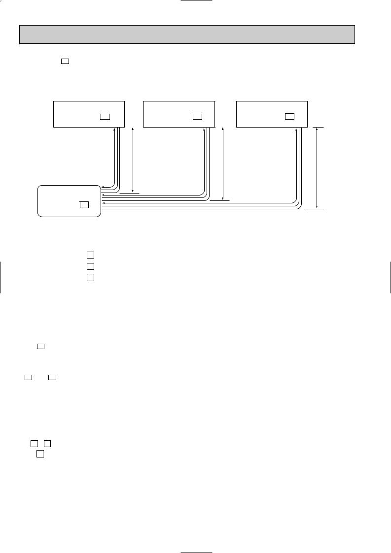
MUX-20TV- E1
MAX.REFRIGERANT PIPING LENGTH & MAX. HEIGHT DIFFERENCE
Indoor unit C |
|
Indoor unit B |
|
Indoor unit A |
MSC-09RV - E3 |
|
MSC-09RV - E3 |
|
MSC-09RV - E3 |
|
|
|
|
|
LC |
H |
LB |
H |
LA |
H
Outdoor unit
MUX-20TV - E1
|
UNIT No. |
|
Pipe length |
|
Height difference (H) |
No. of bends |
|||
|
|
|
|
|
|
|
|
|
|
Max. |
A |
LA |
|
15m |
|
10m |
|
10 |
|
|
|
|
|
|
|
|
|
||
B |
LB |
15m |
LB |
Total |
10m |
10 |
Total |
||
limits |
|||||||||
|
|
+ |
|
|
|||||
|
|
LC |
15m |
30m |
10m |
10 |
15 |
||
|
C |
LC |
|||||||
|
|
|
|||||||
|
|
|
|
|
|
|
|
|
|
Note: The length of piping to individual units (A,B,C) should not exceed 10 meters.
If units B and C are linked, the maximum combined length of piping should not exceed 15 meters.
ADDITIONAL REFRIGERANT CHARGE (R22:g)
|
Outdoor unit |
|
|
|
|
|
|
|
|
|
Refrigerant piping length (one way) |
|
|
|
|
|
|
|||||||||||||||
A unit |
precharged (g) |
|
7m |
|
|
8m |
|
|
9m |
10m |
|
|
11m |
|
12m |
|
13m |
14m |
|
15m |
||||||||||||
|
|
|
|
|
|
|
|
|
|
|
|
|
|
|
|
|
|
|
|
|
|
|
|
|
|
|
|
|
|
|
|
|
|
800 |
|
0 |
|
|
15 |
|
|
30 |
|
45 |
|
|
60 |
|
75 |
90 |
|
105 |
|
120 |
|||||||||||
|
|
|
|
|
|
|
|
|
|
|
|
|
|
|
|
|
|
|
|
|
|
|
|
|
|
|
|
|
|
|
||
|
Outdoor unit |
|
|
|
|
|
|
|
Refrigerant piping length (one way, 2 unit total) |
|
|
|
|
|
|
|||||||||||||||||
|
|
|
|
|
|
|
|
|
|
|
|
|
|
|
|
|
|
|
|
|
|
|
|
|
|
|
|
|
|
|
|
|
B unit + C unit |
precharged (g) |
10m |
11m |
12m |
13m |
14m |
15m |
16m |
17m |
18m |
19m |
20m |
21m |
22m |
23m |
24m |
25m |
26m |
27m |
28m |
29m |
30m |
||||||||||
|
|
|
|
|
|
|
|
|
|
|
|
|
|
|
|
|
|
|
|
|
|
|
|
|
|
|||||||
|
960 |
0 |
|
10 |
20 |
30 |
40 |
50 |
60 |
70 |
|
80 |
90 |
|
100 |
110 |
120 |
130 |
140 |
150 |
160 |
170 |
180 |
190 |
200 |
|||||||
|
|
|
|
|
|
|
|
|
|
|
|
|
|
|
|
|
|
|
|
|
|
|
|
|
|
|
|
|
|
|
|
|
PIPING PREPARATION
1Table below shows the specifications of pipes commercially available.
UNIT No. |
Pipe |
Outside diameter |
Insulation |
Insulation material |
|
|
|||||
mm |
thickness |
||||
|
|
|
|||
|
|
|
|
||
|
|
|
|
|
|
A , B and |
For liquid |
6.35 |
8mm |
Heat resisting foam plastic |
|
C unit |
For gas |
9.52 |
8mm |
0.045 specific gravity |
|
|
2Ensure that the 2 refrigerant pipes are well insulated to prevent condensation. 3Refrigerant bending radius must be 10cm or more.
12
 Loading...