


SPLIT-TYPE, HEAT PUMP AIR CONDITIONERS
OUTDOOR UNIT
SERVICE MANUAL
HFC |
No. OBH469 |
utilized |
|
R410A |
|
Wireless type Models
MUZ-GC25VA - E1 MUZ-GC25VAH - E1 MUZ-GC35VA - E1 MUZ-GC35VAH - E1
MUZ-GC25VA
MUZ-GC25VAH
Indoor unit service manual
MSZ-GC•VA Series (OBH468)
CONTENTS
1.TECHNICAL CHANGES ····································2
2.PART NAMES AND FUNCTIONS······················2
3.SPECIFICATION·················································3
4.NOISE CRITERIA CURVES ·······························5
5.OUTLINES AND DIMENSIONS ·························6
6.WIRING DIAGRAM ············································7
7.REFRIGERANT SYSTEM DIAGRAM ··············11
8.PERFORMANCE CURVES ······························13
9.ACTUATOR CONTROL····································22
10.SERVICE FUNCTIONS·····································23
11.TROUBLESHOOTING ······································23
12.DISASSEMBLY INSTRUCTIONS·····················42
PARTS CATALOG (OBB469)
NOTE:
RoHS compliant products have <G> mark on the spec name plate.
1 
 TECHNICAL CHANGES
MUZ-GA25VA - E3 MUZ-GA25VAH - E3 MUZ-GA35VA - E3 MUZ-GA35VAH - E3
MUZ-GC25VA - E1
MUZ-GC25VAH - E1
MUZ-GC35VA - E1
MUZ-GC35VAH - E1
1.Outdoor model has been changed.
2 
 PART NAMES AND FUNCTIONS
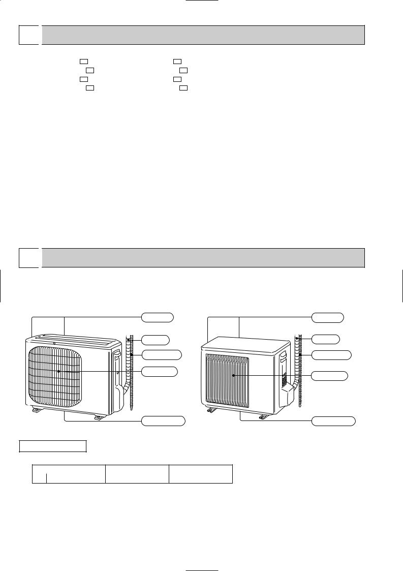
MUZ-GC25VA |
MUZ-GC35VA |
MUZ-GC25VAH |
MUZ-GC35VAH |
Air inlet |
Air inlet |
Piping |
Piping |
Drain hose |
Drain hose |
Air outlet |
Air outlet |
|
Drain outlet |
Drain outlet |
ACCESSORIES
|
MUZ-GC25VA |
MUZ-GC35VA |
1 Drain socket |
1 |
1 |
2
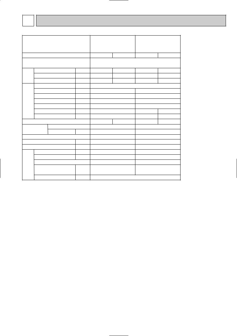
3 SPECIFICATION
Outdoor model
Function
Power supply
Capacity |
Air flow 1 |
K /h |
|
Capacity Rated frequency(Min.-Max.) |
kW |
|
Dehumidification |
r/h |
|
Power outlet |
A |
Electrical data |
Running current 1(Total) |
A |
Starting current 1(Total) |
A |
|
|
Power input 1(Total) |
W |
|
Power factor 1(Total) |
% |
|
Compressor motor current 1 |
A |
|
Fan motor current 1 |
A |
Coefficient of performance(C.O.P) 1(Total)
Compressor |
Model |
|
||
Output |
W |
|||
|
|
|||
|
Fan motor Model |
|
||
|
Dimensions WOHOD |
mm |
||
|
Weight |
|
kg |
|
|
Sound level 1 |
dB(A) |
||
Special remarks |
Fan speed |
rpm |
||
Fan speed regulator |
kg |
|||
|
|
|||
|
Refrigerant filling |
|
||
|
capacity(R410A) |
|
||
|
Refrigeration oil (Model) |
cc |
||
MUZ-GC25VA |
MUZ-GC35VA |
||
MUZ-GC25VAH |
MUZ-GC35VAH |
||
Cooling |
Heating |
Cooling |
Heating |
Single phase 230V,50Hz
2.5 (0.9-3.0) 3.2 (0.9-4.5) 3.5 (1.0-3.9) 4.0 (0.9-5.0)
1.4 |
|
— |
2.0 |
|
— |
1,812 |
1,788 |
2,010 |
2,082 |
||
|
|
|
10 |
|
|
3.6 |
|
4.2 |
5.0 |
|
4.9 |
665 |
|
835 |
1,075 |
|
1,055 |
80 |
|
86 |
93 |
|
94 |
|
4.2 |
|
5.0 |
||
3.14 |
|
4.47 |
4.33 |
||
|
3.74 |
||||
|
0.24 |
0.31 |
0.35 |
||
3.763.83 3.26 3.79
KNB065FDTH(C) |
KNB073FEDH or FGDH |
||||
|
500 |
|
550 |
||
RA6V21-AB or BB |
RC0J50-AM |
||||
684o540o255 |
800o550o285 |
||||
|
26 |
|
31 |
||
46 |
|
47 |
47 |
|
48 |
810 |
|
800 |
810/750 |
|
880/810/650 |
|
1 |
2 |
|
3 |
|
|
0.75 |
|
0.85 |
||
320 (NEO22)
NOTE : Test conditions are based on ISO 5151
Cooling : Indoor |
Dry-bulb temperature 27:Wet-bulb temperature 19: |
Outdoor |
Dry-bulb temperature 35: |
Heating : Indoor |
Dry-bulb temperature 20: |
Outdoor |
Dry-bulb temperature 7: Wet-bulb temperature 6: |
Refrigerant piping length (one way): 5m
1 Measured under rated operating frequency
3
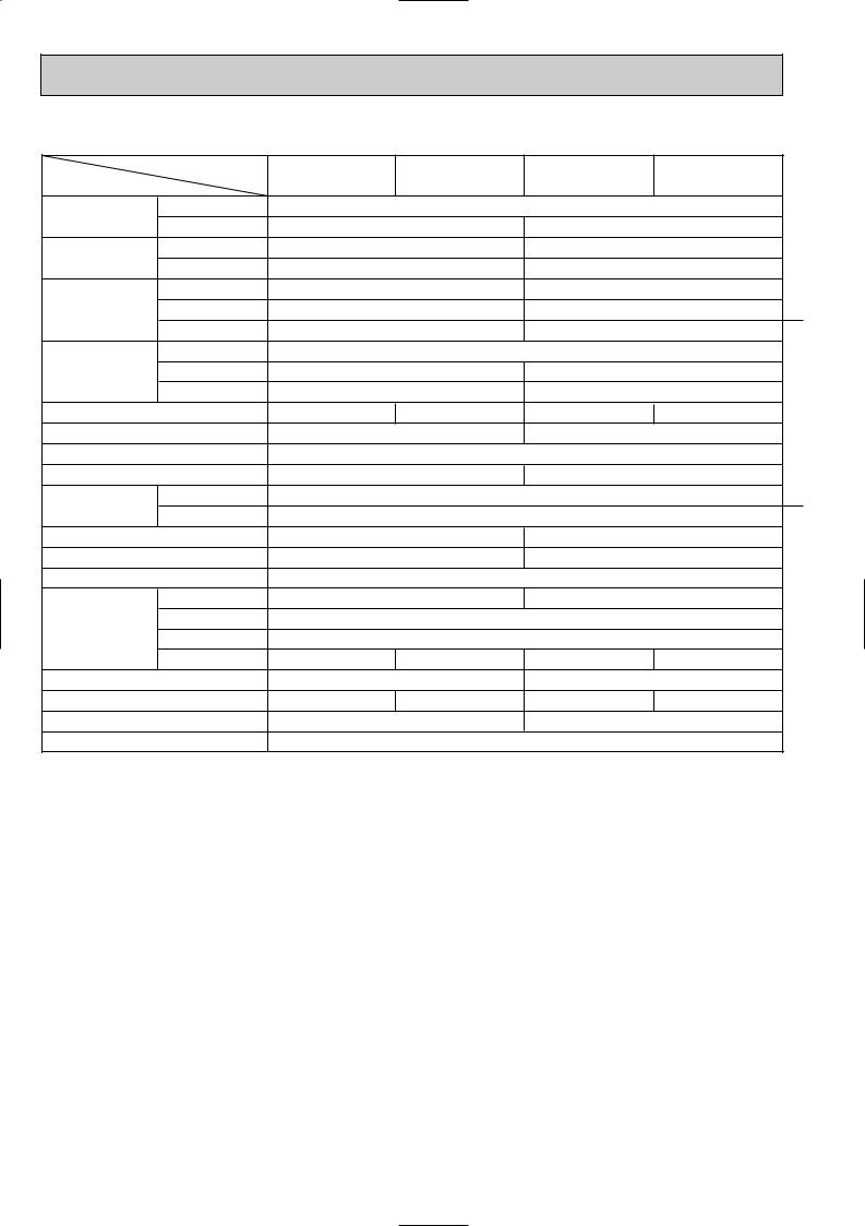
Specifications and rating conditions of main electric parts
Item |
Model |
MUZ-GC25VA |
MUZ-GC25VAH |
MUZ-GC35VA |
MUZ-GC35VAH |
|
|||||
|
|
|
|
|
(CT) (CT761, CT781)
(C61,C62) (C63A, C63B, C63C)
(DB61)
(DB65) (DB61, DB65)
(F61) (F701, F801)
(F71,F801,F901)
Defrost heater |
(H) |
Intelligent power module |
(IPM) |
Expansion valve coil |
(LEV) |
Reactor |
(L61) |
Current-detecting |
(R61) |
resistor |
(R825,R831) |
Current-limiting PTC thermistor (PTC64) Current-limiting resistor (R64A, R64B)
Terminal block |
(TB1,TB2) |
Relay |
(X61) |
|
(X63) |
|
(X64) |
|
(X66) |
R.V. coil |
(21S4) |
Heater protector |
(26H) |
Outdoor fan motor thermal fuse |
|
IGBT |
(TR821) |
|
20A |
|
|
|
— |
|
20A |
|
500+ 420V |
|
— |
|
— |
|
620+ 420V |
|
15A 600V |
|
— |
|
10A 600V |
|
— |
|
— |
|
25A 600V |
|
T20AL250V |
|
|
|
T3.15AL250V |
|
— |
|
— |
|
T3.15AL250V |
— |
230V 130W |
— |
230V 138W |
|
10A 600V |
|
15A 600V |
|
CAM-MD12ME 12VDC |
|
|
|
7A 18.0mH |
|
10A 23.0mH |
|
45m" 5W |
|
|
|
25m" 5W |
|
|
|
33" |
|
— |
|
— |
|
10" 5W |
|
3P |
|
|
|
2A 240V |
|
— |
|
3A 250V |
|
|
|
20A 250V |
|
|
— |
3A 250V |
— |
3A 250V |
|
SHF-4-10W5 |
|
STF-01AJ503 |
— |
Open 45: |
— |
Open 45: |
Open 152: (RA6V21-AB) or Open 126: (RA6V21-BB) |
|
— |
|
|
3A 600V |
|
|
4
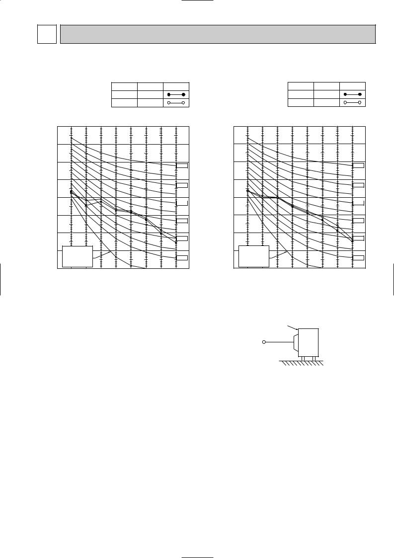
4 NOISE CRITERIA CURVES
MUZ-GC25VA |
|
|
|
|
|
|
|||
MUZ-GC25VAH |
|
|
|
|
|
||||
|
|
|
|
|
FUNCTION |
SPL(dB(A)) |
LINE |
||
|
|
|
|
|
COOLING |
46 |
|
|
|
|
|
|
|
|
HEATING |
47 |
|
|
|
BAR |
90 |
|
|
|
|
|
|
|
|
|
|
|
|
|
|
|
|
|
|
MICRO |
80 |
|
|
|
|
|
|
|
|
|
|
|
|
|
|
|
|
|
|
0.0002 |
70 |
|
|
|
|
|
|
|
NC-70 |
|
|
|
|
|
|
|
|
||
dB re |
60 |
|
|
|
|
|
|
|
|
LEVEL, |
|
|
|
|
|
|
|
|
|
|
|
|
|
|
|
|
|
NC-60 |
|
50 |
|
|
|
|
|
|
|
|
|
PRESSURE |
|
|
|
|
|
|
|
|
|
|
|
|
|
|
|
|
|
NC-50 |
|
40 |
|
|
|
|
|
|
|
|
|
|
|
|
|
|
|
|
|
NC-40 |
|
SOUND |
|
|
|
|
|
|
|
|
|
30 |
|
|
|
|
|
|
|
|
|
BAND |
|
|
|
|
|
|
|
|
NC-30 |
20 |
APPROXIMATE |
|
|
|
|
|
|
||
OCTAVE |
|
|
|
|
|
|
|||
THRESHOLD OF |
|
|
|
|
|
|
|||
|
|
|
|
|
|
|
|||
|
HEARING FOR |
|
|
|
|
|
NC-20 |
||
|
CONTINUOUS |
|
|
|
|
|
|
||
10 |
NOISE |
|
|
|
|
|
|
|
|
|
63 |
125 |
250 |
500 |
1000 |
2000 |
4000 |
8000 |
|
|
|
||||||||
BAND CENTER FREQUENCIES, Hz
MUZ-GC35VA |
|
|
|
|
|
|
|||
MUZ-GC35VAH |
|
|
|
|
|
||||
|
|
|
|
|
FUNCTION |
SPL(dB(A)) |
LINE |
||
|
|
|
|
|
COOLING |
47 |
|
|
|
|
|
|
|
|
HEATING |
48 |
|
|
|
BAR |
90 |
|
|
|
|
|
|
|
|
|
|
|
|
|
|
|
|
|
|
MICRO |
80 |
|
|
|
|
|
|
|
|
|
|
|
|
|
|
|
|
|
|
0.0002 |
70 |
|
|
|
|
|
|
|
NC-70 |
|
|
|
|
|
|
|
|
||
dB re |
60 |
|
|
|
|
|
|
|
|
LEVEL, |
|
|
|
|
|
|
|
|
|
|
|
|
|
|
|
|
|
NC-60 |
|
50 |
|
|
|
|
|
|
|
|
|
PRESSURE |
|
|
|
|
|
|
|
|
|
|
|
|
|
|
|
|
|
NC-50 |
|
40 |
|
|
|
|
|
|
|
|
|
|
|
|
|
|
|
|
|
NC-40 |
|
SOUND |
|
|
|
|
|
|
|
|
|
30 |
|
|
|
|
|
|
|
|
|
BAND |
|
|
|
|
|
|
|
|
NC-30 |
20 |
APPROXIMATE |
|
|
|
|
|
|
||
OCTAVE |
|
|
|
|
|
|
|||
THRESHOLD OF |
|
|
|
|
|
|
|||
|
|
|
|
|
|
|
|||
|
HEARING FOR |
|
|
|
|
|
NC-20 |
||
|
CONTINUOUS |
|
|
|
|
|
|
||
10 |
NOISE |
|
|
|
|
|
|
|
|
|
63 |
125 |
250 |
500 |
1000 |
2000 |
4000 |
8000 |
|
|
|
||||||||
BAND CENTER FREQUENCIES, Hz
Test conditions
Cooling : Dry-bulb temperature 35:
Heating : Dry-bulb temperature 7: Wet-bulb temperature 6:
OUTDOOR UNIT
1m
MICROPHONE
5
5 
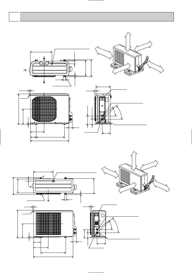
 OUTLINES AND DIMENSIONS
MUZ-GC25VA
MUZ-GC25VAH
381.5
Air in
Air in
Air out
17.5
REQUIRED SPACE
Drain hole [33 (Only MUZ-GC25VA) |
100 |
|
|
mm |
|
|
|
|
|
|
or |
5. |
|
more |
47 |
|
|
Unit: mm
Basically open 100 mm or more without any obstruction in front and on both sides of the unit.
or |
more |
|
|
mm |
|
100 |
|
forpitch installation 264~280 Bolt |
|
|
|
350 |
mm |
or |
|
300 |
or |
more |
|
more |
|||
|
|
||||||
|
|
|
|
||||
mm |
|
|
|
|
|||
100 |
|
|
|
|
|
||
|
|
|
|
|
|
||
40 |
|
Open two sides of left, |
|
|
|
|
|
|
right, or rear side. |
|
|
|
|
||
5 |
|
|
|
|
|
||
.22 |
|
|
|
|
|
|
|
2 holes 10 X 16 |
|
255 |
|
|
|
|
|
|
|
|
|
|
|
|
|
20.8 |
Service panel |
|
540
Handle |
|
|
|
|
|
|
|
|
144.6 |
89.6 |
|
270 |
10 |
|
|
|
|
|
|
|
61 |
|
|
|
|
243 |
Service port |
145.5 |
|
|
105 |
500 |
|
|
|
|
Bolt pitch for installation |
|
|
|
|
|
|
684 |
|
|
|
Liquid refrigerant pipe joint Refrigerant pipe (flared) [6.35
- |
|
40 |
- |
|
43 |
Gas refrigerant pipe joint Refrigerant pipe (flared) [9.52
MUZ-GC35VA MUZ-GC35VAH
REQUIRED SPACE
Basically open 100 mm or more without any obstruction in front and on both sides of the unit.
344.5 |
285 |
550
|
|
|
|
or |
more |
|
|
|
|
|
|
|
Drain hole [42 (MUZ-GC35VA) |
|
|
mm |
|
|
100 |
|
100 |
|
|
400 |
Drain hole [33 (MUZ-GC35VAH) |
mm |
or |
|
|
Air in |
|
|
|
||
|
|
|
|
||
|
|
|
|
more |
|
44 Air in
2 holes 10 X 21
Air out
22.3
Handle
280 10
150
302.5
500 Bolt pitch for installation
800
|
|
pitchBolt for installation 304~325 |
or |
more |
|
|
|
|
|
|
|
|
mm |
|
|
|
|
200 |
|
40 |
17.5 |
|
Open two sides of left, |
|
|
right, or rear side. |
|||
|
|
|||
|
|
|
||
Service panel
23
Liquid refrigerant pipe joint
Refrigerant pipe (flared) [6.35
|
|
|
- |
- |
|
|
|
35 |
43 |
|
164.5 |
|
Gas refrigerant pipe joint |
|
|
|
|
||
|
|
|
Refrigerant pipe (flared) [9.52 |
|
69 |
|
99.5 |
170.5 |
|
|
|
|
||
|
|
|
|
|
Service port
350 |
mm |
|
|
|
or |
|
more |
6

6 
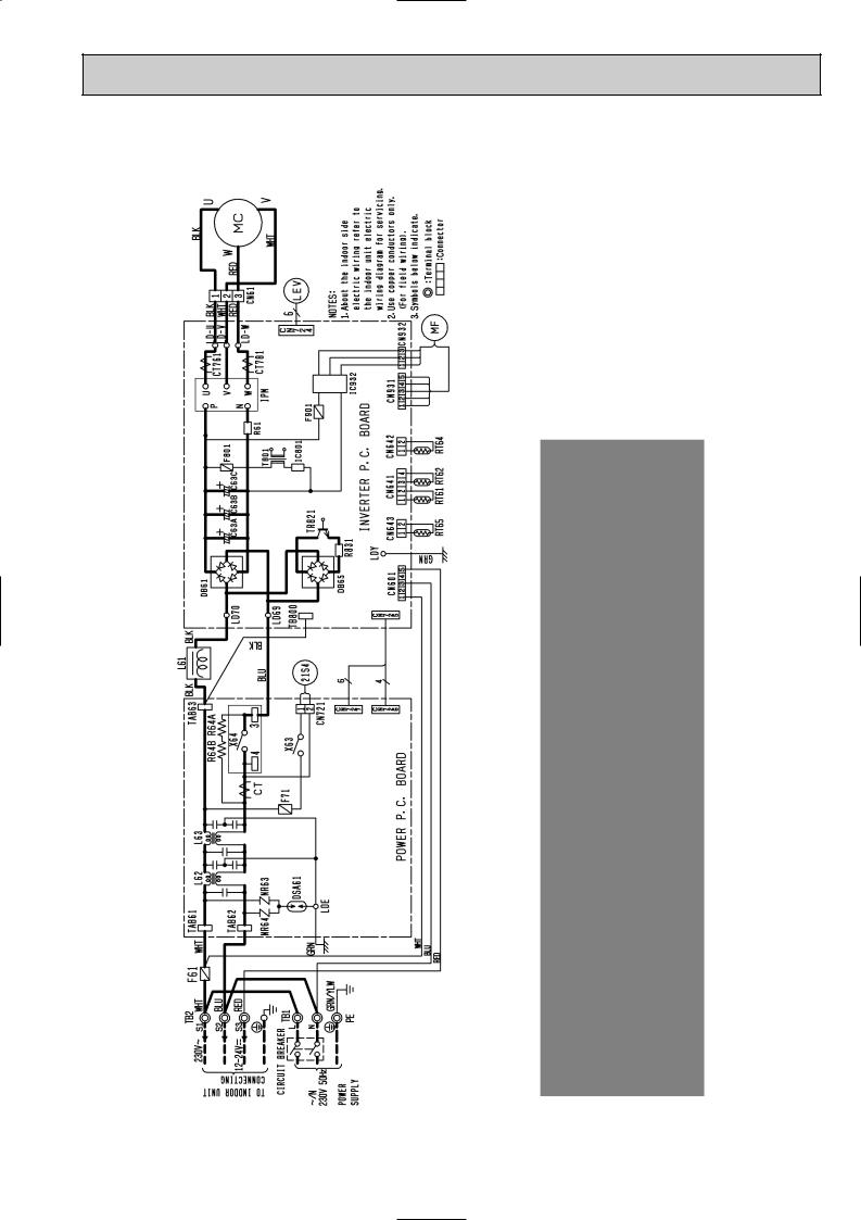
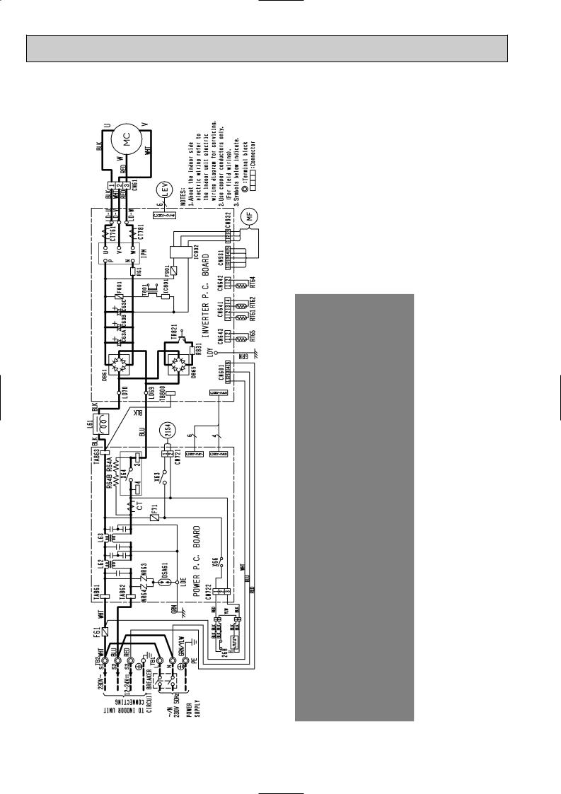
 WIRING DIAGRAM
MUZ-GC25VA
7

MUZ-GC25VAH
8
MUZ-GC35VA
9
MUZ-GC35VAH
10
7 
 REFRIGERANT SYSTEM DIAGRAM
MUZ-GC25VA MUZ-GC25VAH
Refrigerant pipe [9.52 (with heat insulator)
Flared connection
Unit:mm
4-way valve
Muffler 
Stop valve
(with service port)
Discharge |
Muffler |
Outdoor |
|
heat |
|||
|
|||
temperature |
|
exchanger |
|
thermistor |
|
|
|
RT62 |
|
Ambient |
|
|
Compressor |
||
|
temperature |
||
|
|
||
|
Defrost |
thermistor |
|
|
RT65 |
||
|
thermistor |
||
|
RT61 |
|
|
|
|
|
|
|
Strainer |
Flared connection |
|
|
|
#100 |
||
|
Expansion |
|||||
|
Capillary tube |
valve |
||||
|
|
|
|
|
R.V. coil |
|
|
[3.0 [2.0 260 |
|
|
|
|
|
|
|
|
|
|
heating ON |
|
|
|
|
|
|
|
|
|
Stop valve |
|
|
|
|
cooling OFF |
|
|
|
|
|
|
|
Refrigerant pipe [6.35 |
(with strainer) |
|
|
Refrigerant flow in cooling |
||
(with heat insulator) |
|
|
|
|||
|
|
|
Refrigerant flow in heating |
|||
|
|
|
|
|||
MUZ-GC35VA
MUZ-GC35VAH
Refrigerant pipe [9.52 (with heat insulator)
Flared connection
4-way valve
Muffler 
Stop valve
(with service port)
Discharge |
Muffler |
Outdoor |
|
heat |
|||
|
|||
temperature |
|
exchanger |
|
thermistor |
|
|
|
RT62 |
|
Ambient |
|
|
Compressor |
||
|
temperature |
||
|
|
||
|
Defrost |
thermistor |
|
|
RT65 |
||
|
thermistor |
||
|
RT61 |
|
|
|
|
|
|
|
|
Strainer |
Flared connection |
Expansion |
|
|
#100 |
|||
|
|
|
|||||
|
|
|
|
||||
Capillary tube |
valve |
|
|
|
R.V. coil |
||
|
|
|
|
|
|
||
[3.0 [2.0 240 |
Muffler |
|
|
|
|||
|
|
|
heating ON |
||||
Stop valve |
|
|
|
|
|
|
cooling OFF |
|
|
|
|
|
|
||
|
|
|
|
|
|
|
|
Refrigerant pipe [6.35 (with strainer) |
|
|
|
|
Refrigerant flow in cooling |
||
(with heat insulator) |
|
|
|
|
|||
|
|
|
|
Refrigerant flow in heating |
|||
|
|
|
|
|
|||
11
MAX. REFRIGERANT PIPING LENGTH and MAX. HEIGHT DIFFERENCE
|
|
|
|
|
|
Refrigerant piping : m |
Piping size O.D : mm |
||
Model |
|
|
|
|
|
|
|||
|
|
Max. length |
|
Max. Height difference |
|||||
|
|
|
|
|
|||||
|
|
|
|
|
|
|
|
|
|
|
|
|
|
|
A |
|
B |
Gas |
Liquid |
MUZ-GC25VA |
|
|
|
|
|
|
|
|
|
MUZ-GC25VAH |
|
20 |
|
12 |
9.52 |
6.35 |
|||
|
|
|
|
||||||
MUZ-GC35VA |
|
||||||||
|
|
|
|
|
|
|
|
||
MUZ-GC35VAH |
|
|
|
|
|
|
|
|
|
|
|
|
|
|
|
|
|
||
|
|
Indoor |
|
|
|
|
|||
|
|
unit |
|
|
|
|
|||
|
|
|
|
|
|
|
|
|
|
|
|
Max. Height |
|
|
|
|
|||
|
|
difference |
|
|
|
|
|||
|
|
B |
|
|
|
|
|||
|
|
|
|
|
Max. length |
|
|
||
|
|
|
|
|
|
A |
|
|
|
|
|
|
|
|
|
|
Outdoor unit |
|
|
|
|
|
|
|
|
|
|
|
|
ADDITIONAL REFRIGERANT CHARGE (R410A:g)
Model |
Outdoor unit |
|
|
|
Refrigerant piping length (one way) |
|
|
|
||||||
precharged |
5m |
6m |
7m |
8m |
9m |
10m |
11m |
12m |
13m |
14m |
15m |
20m |
||
|
||||||||||||||
MUZ-GC25VA |
750 |
|
|
|
|
|
|
|
|
|
|
|
|
|
|
|
|
|
|
|
|
|
|
|
|
|
|
||
MUZ-GC25VAH |
0 |
0 |
0 |
90 |
120 |
150 |
180 |
210 |
240 |
270 |
300 |
450 |
||
|
||||||||||||||
MUZ-GC35VA |
850 |
|||||||||||||
|
|
|
|
|
|
|
|
|
|
|
|
|||
|
|
|
|
|
|
|
|
|
|
|
|
|
||
MUZ-GC35VAH |
|
|
|
|
|
|
|
|
|
|
|
|
||
|
|
|
|
|
|
|
|
|
|
|
|
|
||
|
|
|
|
|
|
|
|
|
|
|
|
|
|
|
Calculation : Xg=30 g/m (Refrigerant piping length (m)–5)
NOTE: Refrigerant piping exceeding 7 m requires additional refrigerant charge according to the calculation.
12
8 
 PERFORMANCE CURVES
MUZ-GC25VA MUZ-GC35VA
MUZ-GC25VAH MUZ-GC35VAH
The standard data contained in these specifications apply only to the operation of the air conditioner under normal conditions. Since operating conditions vary according to the areas where these units are installed, the following information has been provided to clarify the operating characteristics of the air conditioner under the conditions indicated by the performance curve.
(1)GUARANTEED VOLTAGE
198 ~ 264V, 50Hz
(2)AIR FLOW
Air flow should be set at MAX. |
|
|
|
||
(3) MAIN READINGS |
|
} |
|
||
(1) |
Indoor intake air wet-bulb temperature : |
°C WB |
|
||
(2) |
Indoor outlet air wet-bulb temperature : |
°C WB |
Cooling |
||
|
|||||
(3) |
Outdoor intake air dry-bulb temperature : |
°C DB |
|
||
|
|
||||
(4) |
Total input: |
W |
} |
|
|
(5) |
Indoor intake air dry-bulb temperature : |
°C DB |
Heating |
||
(6) |
Outdoor intake air wet-bulb temperature : |
°C WB |
|||
(7) |
Total input : |
W |
|
||
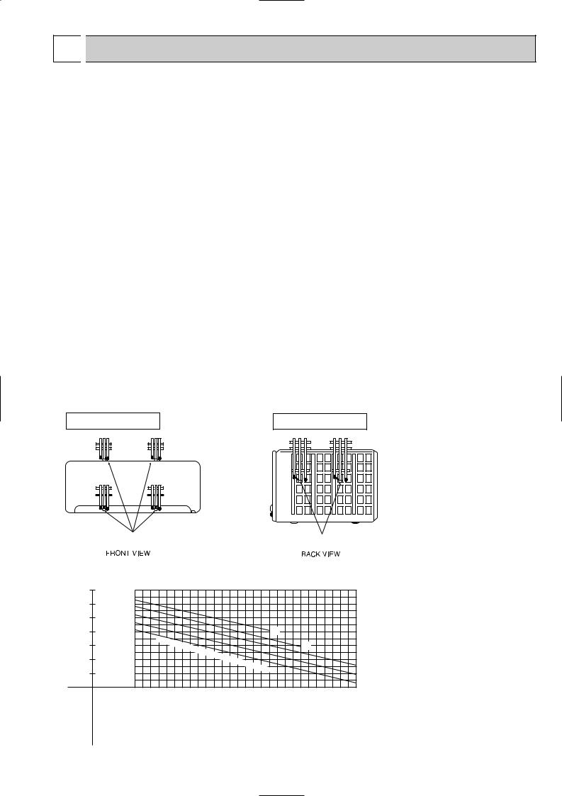
Indoor air wet/dry-bulb temperature difference on the left side of the following chart shows the difference between the indoor intake air wet/dry-bulb temperature and the indoor outlet air wet/dry-bulb temperature for your reference at service.
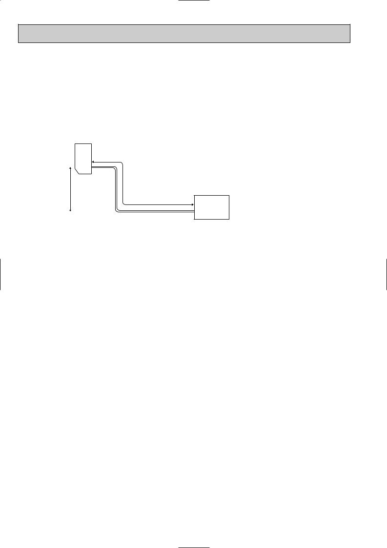
How to measure the indoor air wet-bulb / dry-bulb temperature difference
1.Attach at least 2 sets of wet and dry-bulb thermometers to the indoor air intake as shown in the figure, and at least 2 sets of wet and dry-bulb thermometers to the indoor air outlet. The thermometers must be attached to the position where air speed is high.
2.Attach at least 2 sets of wet and dry-bulb thermometers to the outdoor air intake. Cover the thermometers to prevent direct rays of the sun.
3.Check that the air filter is cleaned.
4.Open windows and doors of room.
5.Press the EMERGENCY OPERATION switch once (twice) to start the EMERGENCY COOL (HEAT) MODE.
6.When system stabilizes after more than 15 minutes, measure temperature and take an average temperature.
7.10 minutes later, measure temperature again and check that the temperature does not change.
INDOOR UNIT |
OUTDOOR UNIT |
Wet and dry-bulb |
Wet and dry-bulb |
thermometers |
thermometers |
8-1. Capacity and input curves
MUZ-GC25VA difference (degree)
Indoor air Wet-bulb temperature
8.1 |
12.7 |
|
1.5 |
|
|
|
Cooling capacity |
|
|
|||
factor |
|
|
|
|
|
|
|
|
|
|||
7.5 |
11.6 |
1.4 |
|
|
|
|
|
|
|
|
|
|
|
|
|
|
|
|
|
|
|
|
|||
6.8 |
10.6 |
correction |
1.3 |
|
|
|
|
|
|
|
|
|
5.7 |
8.7 |
1.1 |
|
|
|
|
|
|
26 |
24 |
|
|
6.3 |
9.6 |
|
1.2 |
|
|
|
|
|
|
|
|
|
|
|
|
|
|
Indoor |
intake |
air |
|
|
|
|
|
|
|
|
|
|
|
|
|
|
|
|
||
|
|
|
|
|
|
|
|
|
|
|
|
|
4.5 |
6.9 |
Capacity |
0.9 |
|
|
|
Wet- |
bulb |
|
|
|
20 |
5.1 |
7.8 |
|
1.0 |
|
|
|
|
temperature |
|
|
|
|
|
|
|
|
|
|
|
|
22 |
||||
|
|
|
|
|
|
|
|
|
(:) |
|
||
|
|
|
|
|
|
|
|
|
|
|
|
18 |
MUZ-GC25VAH at Rated frequency |
MUZ-GC35VA MUZ-GC35VAH |
|
18 |
20 |
|
25 |
|
|
30 |
35 |
40 |
46 |
|
|
|
|
|
|
|
|
|
|
|
||
|
|
|
|
|
|
|
|
|
|
|
13 |
|

MUZ-GC25VA difference (degree)
Indoor air Wet-bulb temperature
6.8 |
10.6 |
|
1.3 |
|
|
Total input (cooling) |
|
|
||
factor |
|
|
|
|
|
|
||||
6.3 |
9.6 |
1.2 |
|
|
|
26 |
24 |
22 |
||
5.7 |
8.7 |
correction |
1.1 |
|
|
|
20 |
|||
|
|
|
|
|
18 |
|||||
|
|
|
|
|
|
|||||
5.1 |
7.8 |
|
1.0 |
|
|
|
|
|
|
|
4.5 |
6.9 |
|
0.9 |
|
|
|
|
|
) |
|
4.0 |
6.0 |
input |
|
|
|
air Wet |
|
(: |
||
0.8 |
|
|
|
temperature |
|
|||||
|
|
|
|
|
|
|
-bulb |
|
|
|
|
|
|
|
|
|
intake |
|
|
|
|
GC25VAH-MUZ frequencyRatedat |
GC35VA-MUZ GC35VAH-MUZ |
frequencyRatedat |
|
|
|
Indoor |
|
|
|
|
18 |
20 |
25 |
30 |
35 |
40 |
46 |
||||
|
|
|
||||||||
|
|
|
|
|
Outdoor intake air Dry-bulb temperature (:) |
|
||||
Indoor air Dry-bulb temperature difference (degree)
20.9
19.3
17.7
16.1
14.5
12.9
11.3
9.7
8.0
6.4
MUZ-GC25VA MUZ-GC25VAH at Rated frequency
27.5 |
|
1.3 |
|
|
Heating capacity |
|
|
15 |
|
|
|
|
|
|
|
|
|||
25.4 |
|
1.2 |
|
|
|
|
|
|
20 |
factor |
|
|
|
|
|
) |
26 |
||
23.3 |
|
|
|
|
|
perature |
(: |
|
|
1.1 |
|
|
|
|
|
|
|||
|
|
|
|
|
|
|
|
||
21.2 |
correction |
1.0 |
|
|
|
-bulb |
tem |
|
|
|
|
|
|
|
|
||||
19.1 |
|
|
|
Indoor |
|
|
|
||
0.9 |
|
|
airDry |
|
|
|
|||
16.9 |
|
0.8 |
|
|
intake |
|
|
|
|
14.8 |
Capacity |
0.7 |
|
|
|
|
|
|
|
12.7 |
0.6 |
|
|
|
|
|
|
|
|
|
|
|
|
|
|
|
|
||
10.6 |
|
0.5 |
|
|
|
|
|
|
|
|
|
|
|
|
|
|
|
|
|
8.5 |
|
0.4 |
|
|
|
|
|
|
|
GC35VA-MUZ GC35VAH-MUZ frequencyRatedat |
|
|
|
|
|
|
|
|
|
|
-20 |
-15 |
-10 |
-5 |
0 |
5 |
10 |
15 |
|
|
|
||||||||
|
|
|
Outdoor intake air Wet-bulb temperature (:) |
|
|||||
Indoor air Dry-bulb temperature difference (degree)
20.9
19.3
17.7
16.1
14.5
12.9
11.3
9.7
8.0
6.4
MUZ-GC25VA MUZ-GC25VAH at Rated frequency
27.5 |
|
1.3 |
|
Total input(heating) |
|
|
|
|||
|
|
|
|
|
|
|
|
|
||
25.4 |
factor |
1.2 |
|
|
|
|
|
|
|
26 |
23.3 |
1.1 |
|
|
|
|
|
) |
|
20 |
|
|
|
|
|
|
|
(: |
|
15 |
||
21.2 |
|
|
|
|
|
|
temperature |
|
|
|
correction |
1.0 |
|
|
|
-bulb |
|
|
|
||
|
|
|
|
|
|
|
|
|
||
19.1 |
|
0.9 |
|
|
air |
Dry |
|
|
|
|
|
|
intake |
|
|
|
|
|
|||
|
|
|
|
|
|
|
|
|||
|
|
|
|
|
|
|
|
|
|
|
16.9 |
|
0.8 |
|
Indoor |
|
|
|
|
|
|
|
|
|
|
|
|
|
|
|
||
14.8 |
Input |
0.7 |
|
|
|
|
|
|
|
|
12.7 |
0.6 |
|
|
|
|
|
|
|
|
|
|
|
|
|
|
|
|
|
|
||
10.6 |
|
0.5 |
|
|
|
|
|
|
|
|
|
|
|
|
|
|
|
|
|
|
|
8.5 |
|
0.4 |
|
|
|
|
|
|
|
|
GC35VA-MUZ GC35VAH-MUZ frequencyRatedat |
|
|
|
|
|
|
|
|
|
|
|
-20 |
-15 |
-10 |
|
-5 |
0 |
5 |
10 |
15 |
|
|
|
|
||||||||
|
|
|
Outdoor intake air Wet-bulb temperature (:) |
|
||||||
NOTE:The above broken lines are for the heating operation without any frost and defrost operation.
14
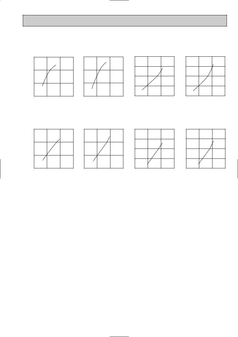
8-2. Capacity and input correction by operational frequency of compressor
MUZ-GC25VA
MUZ-GC25VAH
Capacity correction factors
|
Correction of Cooling capacity |
|
Correction of Cooling total input |
|||||
1.5 |
|
|
correctionInputfactors |
1.5 |
|
|
correctionCapacityfactors |
|
1.0 |
|
|
1.0 |
|
|
|||
|
|
|
|
|
|
|||
0.5 |
|
|
|
0.5 |
|
|
|
|
0.0 |
50 |
100 |
|
0.0 |
50 |
100 |
150(Hz) |
|
0 |
150(Hz) |
0 |
||||||
Correction of Heating capacity
2.0 |
|
|
|
1.5 |
|
|
factors |
1.0 |
|
|
correction |
|
|
|
|
0.5 |
|
|
Input |
|
|
|
|
0.0 |
50 |
100 |
150(Hz) |
0 |
Correction of Heating total input 2.0
1.5
1.0
0.5
0.0 |
50 |
100 |
150(Hz) |
0 |
The operational frequency of compressor The operational frequency of compressor The operational frequency of compressor The operational frequency of compressor
MUZ-GC35VA
MUZ-GC35VAH
Capacity correction factors
Correction of Cooling capacity |
|||
1.5 |
|
|
|
1.0 |
|
|
factors |
0.5 |
|
|
correction |
|
|
|
Input |
0.0 |
50 |
100 |
150(Hz) |
0 |
|||
Correction of Cooling total input
1.5
1.0 |
|
|
factors |
|
|
correction |
|
0.5 |
|
|
|
|
|
Capacity |
|
|
|
|
|
0.0 |
50 |
100 |
150(Hz) |
0 |
Correction of Heating capacity
2.0
1.5 |
|
|
factors |
1.0 |
|
|
correction |
|
|
|
|
0.5 |
|
|
Input |
|
|
|
|
0.0 |
50 |
100 |
150(Hz) |
0 |
Correction of Heating total input 2.0
1.5
1.0
0.5
0.0 |
50 |
100 |
150(Hz) |
0 |
The operational frequency of compressor The operational frequency of compressor The operational frequency of compressor The operational frequency of compressor
8-3. Test run operation (How to operate fixed-frequency operation)
1.Press EMERGENCY OPERATION switch to COOL or HEAT mode (COOL : Press once, HEAT : Press twice).
2.Test run operation starts and continues to operate for 30 minutes.
3.Compressor operates at rated frequency in COOL mode or 58Hz in HEAT mode.
4.Indoor fan operates at High speed.
5.After 30 minutes, test run operation finishes and EMERGENCY OPERATION starts (Operation frequency of compressor varies).
6.To cancel test run operation (EMERGENCY OPERATION), press EMERGENCY OPERATION switch or any button on remote controller.
15
 Loading...