


SPLIT-TYPE AIR CONDITIONERS
No. OB183
SECOND EDITION
SERVICE MANUAL
Wireless type
Models
MSX-05NV - E1
MSX-09NV - E1
MSX-12NV - E1
(WH)●MUX-10NV - E1 (WH)●MUX-18NV - E1 (WH)●MUX-24NV - E1
CONTENTS
1.TECHNICAL CHANGES ····································2
2.PART NAMES AND FUNCTIONS······················3
3.SPECIFICATION·················································6
4.OUTLINES AND DIMENSIONS ·························9
5.WIRING DIAGRAM···········································11
6.REFRIGERANT SYSTEM DIAGRAM ··············14
7.PERFORMANCE CURVES ······························21
8.MICROPROCESSOR CONTROL ····················23
9.SERVICE FUNCTIONS ····································30
10.TROUBLESHOOTING······································31
11.DISASSEMBLY INSTRUCTIONS·····················37
12.PARTS LIST······················································46
13.OPTIONAL PARTS ····································BACK
1 TECHNICAL CHANGES
MSX-10LV- E2 MSX-10NV- E1
MSX-18LV- E2 MSX-18NV- E1
MSX-24NV- E1 New model
Connectable unit table
INDOOR UNIT |
OUTDOOR UNIT |
|
MSX-05NV x 2 |
MUX-10NV- E1 |
|
MSX-09NV x 2 or x 3 |
MUX-18NV- E1 |
|
MSX-09NV x 1 or x 2 |
MUX-24NV- E1 |
|
MSX-12NV x 1 or x 2 |
||
|
It is not connected except above connection of indoor unit and outdoor unit.
1. |
Indoor unit |
has changed. |
|
|
|
||
2. |
Indoor fan |
has changed. (RC2V17-AA |
|
|
RC4V19-AA) |
||
|
|
||||||
3. |
Compressor |
changed. (KH-134VLC |
|
|
KH-134VLL) |
||
|
|||||||
4.Remote controller model has changed.
5.Microprocessor controller has changed.
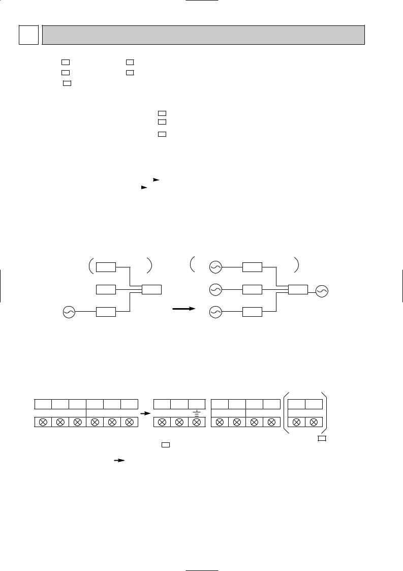
6.The receiving system has changed.
INDOOR |
OUTDOOR |
INDOOR |
OUTDOOR |
|
|
220/240V |
220/240V.50Hz |
|
12VDC |
|
|
|
||
|
MSX-18NV |
|
|
MSX-18NV |
|
|
|
|
|
220/240V |
220/240V.50Hz |
12VDC |
||
220/240V |
|
220/240V.50Hz |
|
220/240V |
50Hz |
220/240V |
|
|
50Hz |
|
|
|
12VDC |
|
7. Terminal block has changed.
|
L N 2 L N 2 |
L N |
2 1 2 1 |
2 1 |
8. |
Wiring diagram has changed. |
|
|
MSX-18NV- E1 |
9. |
Compressor protector has changed. (MSX-18NV- E1 ) |
|
|
|
|
THERMAL SWITCH |
|
|
|
|
OVERCURRENT RELAY |
OVERCURRENT RELAY (INNER THERMOSTAT) |
|
|
2
2 
 PART NAMES AND FUNCTIONS
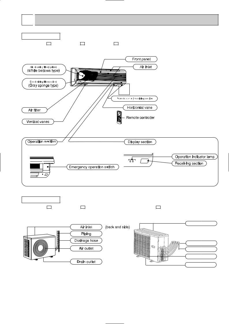
INDOOR UNIT
MSX-05NV- E1 , MSX-09NV- E1 , MSX-12NV- E1
(When the front panel is open)
OUTDOOR UNIT
MUX-10NV- E1 , MUX-18NV- E1 |
MUX-24NV- E1 |
Air inlet (back and side)
Piping
Drainage hose
Air outlet
Drain outlet
3
MSX-05NV- E1
MSX-09NV- E1
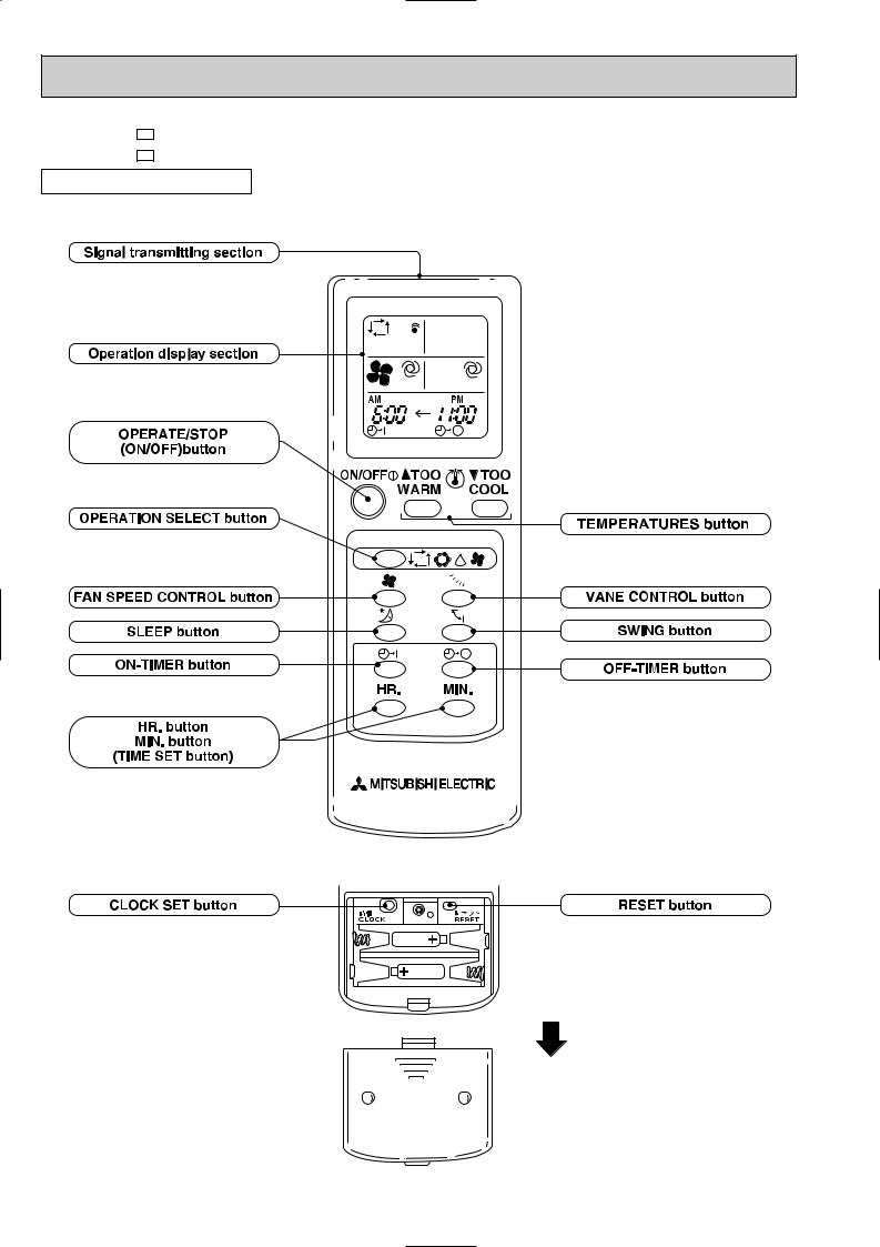
REMOTE CONTROLLER


 .
.
4
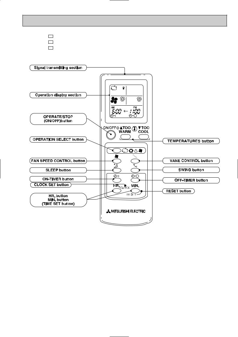
MSX-05NV- E1 (Product number 7000501T~)
MSX-09NV- E1 (Product number 7000701T~)
MSX-12NV- E1
5

3 |
|
|
SPECIFICATION |
|
|
|
|
|||||
|
|
|
|
|
|
|
|
|
|
|
|
|
|
|
|
|
|
|
|
|
|
|
|
|
|
|
|
|
Model |
|
|
MSX-10NV- E1 |
INDOOR MSX-05NV- E1 |
OUTDOOR MUX-10NV- E1 |
|
|||
|
|
|
|
|
|
|
|
|
|
|
||
|
|
|
Function |
|
|
|
Cooling |
|
|
|||
|
|
|
Power supply |
|
|
Single phase, 220-240V, 50Hz |
|
|||||
|
|
|
Unit No. |
|
|
|
Single |
|
Double |
|
||
|
|
|
|
|
|
A or B |
|
A + B |
|
|||
|
|
|
|
|
|
|
|
|
|
|
||
|
|
|
|
|
|
|
|
|
|
|
|
|
|
|
|
Capacity |
|
|
kW |
|
2.2 |
|
1.3x2 |
|
|
Capacity |
Dehumidification |
|
R/h |
|
0.8 |
|
0.2x2 |
|
||||
Air flow |
|
Indoor |
K/h |
|
492 |
|
492x2 |
|
||||
|
|
|
|
|
|
|
||||||
|
|
|
|
Outdoor |
K/h |
|
1,560 |
|
1,560 |
|
||
|
|
|
|
|
|
|
|
|||||
|
|
|
Power outlet |
|
|
A |
|
10 |
|
|
||
|
|
|
Running |
|
Indoor |
A |
|
0.17 |
|
0.17x2 |
|
|
|
|
|
current |
Outdoor |
A |
3.33-3.43 |
|
3.36-3.46 |
|
|||
|
|
|
Power input |
|
Indoor |
W |
|
35 |
|
35x2 |
|
|
|
|
|
|
Outdoor |
W |
705-755 |
|
720-760 |
|
|||
|
|
|
|
|
|
|
||||||
Electrical |
Auxiliary heater |
|
|
A(kW) |
|
– |
|
– |
|
|||
|
|
Indoor |
% |
|
94–86 |
|
94–86 |
|
||||
data |
Power factor |
|
|
|
|
|||||||
|
Outdoor |
% |
|
96-92 |
|
97-92 |
|
|||||
|
|
|
|
|
|
|
|
|||||
|
|
|
Starting current |
|
|
A |
|
17 |
|
|
||
|
|
|
Compressor motor current |
A |
3.05-3.15 |
|
3.25-3.35 |
|
||||
|
|
|
Fan motor |
|
Indoor unit |
A |
|
0.17 |
|
0.17x2 |
|
|
|
|
|
current |
Outdoor unit |
A |
|
0.27 |
|
|
|||
Coefficient of performance(C.O.P) |
|
|
2.97-2.78 |
|
3.29-3.13 |
|
||||||
|
|
|
Model |
|
|
|
|
KH - 134VLL |
|
|
||
Compressor |
Output |
|
|
W |
|
650 |
|
|
||||
|
|
|
Winding resistance (at 20:) |
" |
|
C -R 4.66 C -S 8.20 |
|
|
||||
Indoor |
Model |
|
|
|
|
RC4V 19 - A A |
|
|
||||
fan motor |
Winding resistance (at 20:) |
" |
|
WHT - BLK 292 BLK - RED 324 |
|
|||||||
Outdoor |
Model |
|
|
|
|
RA6V22 - BC |
|
|
||||
fan motor |
Winding resistance (at 20:) |
" |
|
WHT - BLK 325.0 BLK - RED 393.3 |
|
|||||||
|
|
|
|
|
Width |
mm |
|
815 |
|
|
||
|
|
|
Indoor unit |
|
Height |
mm |
|
275 |
|
|
||
Dimensions |
|
|
Depth |
mm |
|
183 |
|
|
||||
|
|
Width |
mm |
|
760 |
|
|
|||||
|
|
|
|
|
|
|
|
|||||
|
|
|
Outdoor unit |
|
Height |
mm |
|
540 |
|
|
||
|
|
|
|
|
Depth |
mm |
|
230 |
|
|
||
Weight |
Indoor unit |
|
|
kg |
|
8 |
|
|
||||
Outdoor unit |
|
|
kg |
|
31 |
|
|
|||||
|
|
|
|
|
|
|
|
|||||
|
|
|
Air direction |
|
|
|
|
5 |
|
|
||
|
|
|
Sound level |
|
Indoor unit |
dB |
|
37 |
|
|
||
|
|
|
(Hi) |
|
Outdoor unit |
dB |
|
46 - 47 |
|
|
||
|
|
|
Fan speed |
|
Indoor unit |
rpm |
|
1,100 |
|
|
||
Special |
(Hi) |
|
Outdoor unit |
rpm |
|
700 |
|
|
||||
remarks |
Fan speed |
|
Indoor unit |
|
|
4 |
|
|
||||
|
|
|
regulator |
|
Outdoor unit |
|
|
1 |
|
|
||
|
|
|
Refrigerant filling capacity(R-22) |
kg |
|
1.15 |
|
|
||||
|
|
|
Thermistor |
|
RT11(at 25:) |
k" |
|
10 |
|
|
||
|
|
|
|
RT12(at 25:) |
k" |
|
10 |
|
|
|||
|
|
|
|
|
|
|
|
|||||
NOTE:Test conditions |
|
|
|
|
|
|
|
|
||||
|
Cooling : Indoor |
DB27°C / WB19°C |
|
|
|
|
||||||
|
|
|
Outdoor |
DB35°C / WB24°C |
|
|
|
|
||||
6

|
|
|
|
|
|
|
|
|
|
|
|
|
|
|
|
|
|
|
|
|
|
|
|
|
|
|
|
|
|
|
Model |
|
|
MSX-18NV- E1 |
INDOOR UNIT MSX-09NV- E1 |
OUTDOOR UNIT MUX-18NV- E1 |
||||||||
|
|
|
|
|
|
|
|
|
|
|
||||
|
Function |
|
|
|
|
|
Cooling |
|
|
|
||||
|
Power supply |
|
|
|
|
Single phase, 220-240V, 50Hz |
|
|||||||
|
Unit No. |
|
|
|
Single |
|
Double |
|
Double |
|
Triple |
|||
|
|
|
|
A or B or C |
|
A + B or A + C |
|
|
B + C |
|
A + B + C |
|||
|
|
|
|
|
|
|
|
|
|
|
||||
|
|
|
|
|
|
|
|
|
|
|
|
|
|
|
|
Capacity |
|
|
kW |
|
2.3 |
|
2.1x2 |
|
|
1.3x2 |
|
2.1+1.3x2 |
|
Capacity |
Dehumidification |
|
R/h |
|
0.9 |
|
0.8x2 |
|
|
0.2x2 |
|
0.8+0.2x2 |
||
Air flow |
|
Indoor |
K/h |
|
492 |
|
492x2 |
|
|
492x2 |
|
492x3 |
||
|
|
|
|
|
|
|
||||||||
|
|
Outdoor |
K/h |
|
1,320 |
|
1,980 |
|
|
1,320 |
|
1,980 |
||
|
|
|
|
|
|
|
|
|||||||
|
Power outlet |
|
|
A |
|
|
|
|
15 |
|
|
|
||
|
Running |
|
Indoor |
A |
|
0.17 |
|
0.17x2 |
|
|
0.17x2 |
|
0.17x3 |
|
|
current |
|
Outdoor |
A |
|
3.63-3.73 |
|
7.06-7.16 |
|
3.66-3.76 |
|
7.09-7.19 |
||
|
Power input |
|
Indoor |
W |
|
35 |
|
35x2 |
|
|
35x2 |
|
35x3 |
|
|
|
Outdoor |
W |
|
755-795 |
|
1500-1580 |
|
760-810 |
|
1495-1585 |
|||
|
|
|
|
|
|
|
||||||||
Electrical |
Auxiliary heater |
|
|
A(kW) |
|
– |
|
– |
|
|
– |
|
– |
|
Power factor |
|
Indoor |
% |
|
94-86 |
|
94-86 |
|
|
94-86 |
|
94-86 |
||
data |
|
|
|
|
|
|
||||||||
|
Outdoor |
% |
|
95-89 |
|
97-92 |
|
|
94-90 |
|
96-92 |
|||
|
|
|
|
|
|
|
|
|||||||
|
Starting current |
|
|
A |
|
17 |
|
17x2 |
|
|
17 |
|
17x2 |
|
|
Compressor motor current |
A |
|
3.3-3.4 |
|
6.67-6.77 |
|
3.32-3.42 |
|
6.69-6.79 |
||||
|
Fan motor |
|
Indoor unit |
A |
|
0.17 |
|
0.17x2 |
|
|
0.17x2 |
|
0.17x3 |
|
|
current |
|
Outdoor unit |
A |
|
0.32 |
|
0.37 |
|
|
0.32 |
|
0.37 |
|
Coefficient of performance(C.O.P) |
|
|
|
2.91-2.77 |
|
2.68-2.55 |
|
3.13-2.95 |
|
2.94-2.78 |
||||
|
Model |
|
|
|
|
|
|
KH-134VLLx2 |
|
|
|
|||
Compressor |
Output |
|
|
W |
|
|
|
650x2 |
|
|
|
|||
|
Winding resistance (at 20:) |
" |
|
|
|
C-R 4.66, C-S 8.20 |
|
|||||||
Indoor |
Model |
|
|
|
|
|
|
RC4V19-AA |
|
|
|
|||
fan motor |
Winding resistance (at 20:) |
" |
|
|
|
WHT-BLK 292 |
|
BLK-RED 324 |
|
|||||
Outdoor |
Model |
|
|
|
|
|
|
RA6V50-CB or RA6V50-CC |
|
|||||
fan motor |
Winding resistance (at 20:) |
" |
|
|
WHT-BLK117.3 BLK-YLW 65 |
YLW-RED 49.6 |
|
|||||||
|
|
|
Width |
mm |
|
|
815 |
|
|
|
||||
|
Indoor unit |
|
Height |
mm |
|
|
275 |
|
|
|
||||
Dimensions |
|
|
Depth |
mm |
|
|
183 |
|
|
|
||||
|
|
Width |
mm |
|
|
850 |
|
|
|
|||||
|
|
|
|
|
|
|
|
|||||||
|
Outdoor unit |
|
Height |
mm |
|
|
605 |
|
|
|
||||
|
|
|
Depth |
mm |
|
|
290 |
|
|
|
||||
Weight |
Indoor unit |
|
|
kg |
|
|
|
|
8 |
|
|
|
||
Outdoor unit |
|
|
kg |
|
|
|
|
54 |
|
|
|
|||
|
|
|
|
|
|
|
|
|
|
|||||
|
Air direction |
|
|
|
|
|
|
|
5 |
|
|
|
||
|
Sound level |
|
Indoor unit |
dB |
|
|
|
|
37 |
|
|
|
||
|
(Hi) |
|
Outdoor unit |
dB |
|
|
|
|
53 |
|
|
|
||
|
Fan speed |
|
Indoor unit |
rpm |
|
|
1,100 |
|
|
|
||||
Special |
(Hi) |
|
Outdoor unit |
rpm |
|
|
830-860 |
|
|
|
||||
remarks |
Fan speed |
|
Indoor unit |
|
|
|
|
|
4 |
|
|
|
||
|
regulator |
|
Outdoor unit |
|
|
|
|
|
2 |
|
|
|
||
|
Refrigerant filling capacity(R-22) |
kg |
|
|
0.75+0.75 |
|
|
|
||||||
|
Thermistor |
|
RT11(at 25:) |
k" |
|
|
|
|
10 |
|
|
|
||
|
|
RT12(at 25:) |
k" |
|
|
|
|
10 |
|
|
|
|||
|
|
|
|
|
|
|
|
|
|
|||||
NOTE:Test conditions |
|
|
|
|
|
|
|
|
|
|
|
|
||
Cooling : Indoor |
DB27°C / WB19°C |
|
|
|
|
|
|
|
|
|||||
|
Outdoor |
DB35°C / WB24°C |
|
|
|
|
|
|
|
|
||||
7

|
|
|
|
|
|
|
|
|
|
|
|
|
|
|
|
|
|
|
|
|
|
|
|
|
|
|
|
|
|
|
|
|
Model |
|
|
MSX-24NV- E1 INDOOR UNIT MSX-09NV- |
OUTDOOR UNIT MUX-24NV- E1 |
||||||||||
|
|
|
|
|
|
|
|
|
|
|
|
E1 |
|
|
|
|
|
|
|
|
|
|
|
|
MSX-12NV- E1 |
|
|
|
|||
|
Function |
|
|
|
|
|
Cooling |
|
|
|
|||||
|
Power supply |
|
|
|
Single phase, 220-240V, 50Hz |
|
|
||||||||
|
|
|
|
|
|
Single |
Single |
Double |
Double |
|
|
Double |
Triple |
Triple |
Four |
|
Unit No. |
|
|
|
A+C or A+D |
A+B+C or |
A+C+D or |
||||||||
|
|
|
A or B |
C or D |
A+B |
C+D |
|
A+B+C+D |
|||||||
|
|
|
|
|
|
|
B+C or B+D |
A+B+D |
B+C+D |
||||||
|
|
|
|
|
|
|
|
|
|
|
|
||||
|
Capacity |
|
|
kW |
3.4 |
2.6 |
2.0x2 |
1.7x2 |
|
|
3.1+2.3 |
1.95x2+2.2 |
2.9+1.55x2 |
1.95x2+1.55x2 |
|
Capacity |
Dehumidification |
|
R/h |
1.6 |
1.2 |
0.5x2 |
0.3x2 |
|
|
1.4+0.8 |
0.5x2+0.8 |
1.3+0.3x2 |
0.5x2+0.3x2 |
||
Air flow |
|
Indoor |
K/h |
558 |
492 |
558x2 |
492x2 |
|
|
558+492 |
558x2+492 |
558+492x2 |
558x2+492x2 |
||
|
|
|
|
||||||||||||
|
|
Outdoor |
K/h |
|
|
|
2400-2640 |
|
|
|
|||||
|
|
|
|
|
|
|
|
|
|||||||
|
Power outlet |
|
|
A |
|
|
|
|
25 |
|
|
|
|
||
|
Running |
|
Indoor |
A |
0.17 |
0.17 |
0.17x2 |
0.17x2 |
|
|
0.17x2 |
0.17x3 |
0.17x3 |
0.17x4 |
|
|
current |
|
Outdoor |
A |
6.2-6.0 |
4.4-4.3 |
6.5-6.5 |
4.6-4.4 |
|
10.8-10.4 |
11.1-10.6 |
11.1-10.6 |
11.5-10.9 |
||
|
Power input |
|
Indoor |
W |
35 |
35 |
35x2 |
35x2 |
|
|
35x2 |
35x3 |
35x3 |
35x4 |
|
|
|
Outdoor |
kW |
1.32-1.38 |
0.94-0.98 |
1.39-1.49 |
0.98-1.02 |
|
2.33-2.40 |
2.37-2.45 |
2.37-2.45 |
2.45-2.50 |
|||
|
|
|
|
||||||||||||
Electrical |
Auxiliary heater |
|
|
A(kW) |
– |
– |
– |
– |
|
|
– |
– |
– |
– |
|
Power factor |
|
Indoor |
% |
94–86 |
94–86 |
94–86 |
94–86 |
|
|
94–86 |
94–86 |
94–86 |
94–86 |
||
data |
|
|
|
||||||||||||
|
Outdoor |
% |
97-96 |
97-96 |
97-96 |
97-96 |
|
|
97-96 |
97-96 |
97-96 |
97-96 |
|||
|
|
|
|
|
|||||||||||
|
Starting current |
|
|
A |
|
|
|
|
48 |
|
|
|
|
||
|
Compressor motor current |
A |
6.2-6.0 |
4.4-4.2 |
6.2-6.0 |
4.4-4.2 |
|
10.6-10.2 |
10.6-10.2 |
10.6-10.2 |
10.6-10.2 |
||||
|
Fan motor |
|
Indoor unit |
A |
0.17 |
0.17 |
0.17x2 |
0.17x2 |
|
|
0.17x2 |
0.17x3 |
0.17x3 |
0.17x4 |
|
|
current |
|
Outdoor unit |
A |
|
|
|
0.28-0.31 |
|
|
|
||||
Coefficient of performance(C.O.P) |
|
|
2.51-2.40 |
2.67-2.56 |
2.74-2.56 |
3.24-3.12 |
|
2.25-2.19 |
2.46-2.39 |
2.42-2.35 |
2.70-2.65 |
||||
|
Model |
|
|
|
|
|
RH-174VGH+RH-231VHA |
|
|
||||||
Compressor |
Output |
|
|
W |
|
|
RH-174VGH 800 |
|
RH-231VHA 1100 |
|
|
||||
|
Winding resistance (at 20:) |
" |
|
RH-174VGH C-R3.30 C-S5.80 |
|
|
RH-231VHA C-R2.13 C-S3.91 |
||||||||
Indoor |
Model |
|
|
|
|
|
|
RC4V19-AA |
|
|
|
||||
fan motor |
Winding resistance (at 20:) |
" |
|
|
WHT-BLK 292 |
|
BLK-RED 324 |
|
|
||||||
Outdoor |
Model |
|
|
|
|
|
|
RA6V25-AA |
|
|
|
||||
fan motor |
Winding resistance (at 20:) |
" |
|
|
WHT-BLK142 BLK-RED135 |
|
|
||||||||
|
|
|
Width |
mm |
|
|
|
815 |
|
|
|
|
|||
|
Indoor unit |
|
Height |
mm |
|
|
|
275 |
|
|
|
|
|||
Dimensions |
|
|
Depth |
mm |
|
|
|
183 |
|
|
|
|
|||
|
|
Width |
mm |
|
|
|
750 |
|
|
|
|
||||
|
|
|
|
|
|
|
|
|
|
||||||
|
Outdoor unit |
|
Height |
mm |
|
|
|
900 |
|
|
|
|
|||
|
|
|
Depth |
mm |
|
|
|
330 |
|
|
|
|
|||
Weight |
Indoor unit |
|
|
kg |
|
|
|
|
8 |
|
|
|
|
||
Outdoor unit |
|
|
kg |
|
|
|
|
72 |
|
|
|
|
|||
|
|
|
|
|
|
|
|
|
|
|
|||||
|
Air direction |
|
|
|
|
|
|
|
5 |
|
|
|
|
||
|
Sound level |
|
Indoor unit |
dB |
|
|
MSX-09NV 37 |
|
MSX-12NV 42 |
|
|
||||
|
(Hi) |
|
Outdoor unit |
dB |
|
|
|
|
49 |
|
|
|
|
||
|
Fan speed |
|
Indoor unit |
rpm |
|
|
MSX-09NV 1100 |
|
MSX-12NV 1230 |
|
|
||||
Special |
(Hi) |
|
Outdoor unit |
rpm |
|
|
|
530-570 |
|
|
|
||||
remarks |
Fan speed |
|
Indoor unit |
|
|
|
|
|
4 |
|
|
|
|
||
|
regulator |
|
Outdoor unit |
|
|
|
|
|
1 |
|
|
|
|
||
|
Refrigerant filling capacity(R-22) |
kg |
|
|
|
1.15+1.15 |
|
|
|
||||||
|
Thermistor |
|
RT11(at 25:) |
k" |
|
|
|
|
10 |
|
|
|
|
||
|
|
RT12(at 25:) |
k" |
|
|
|
|
10 |
|
|
|
|
|||
|
|
|
|
|
|
|
|
|
|
|
|||||
NOTE:Test conditions |
|
|
|
|
|
|
|
|
|
|
|
|
|
||
Cooling : Indoor |
DB27°C / WB19°C |
|
|
|
|
|
|
|
|
|
|||||
|
Outdoor |
DB35°C / WB24°C |
|
|
|
|
|
|
|
|
|
||||
8

4 
 OUTLINES AND DIMENSIONS
INDOOR UNIT |
Unit : mm |
|
MSX-05NV- E1 |
, MSX-09NV- E1 |
|
MSX-12NV- E1 |
|
|
OUTDOOR UNIT
MUX10NV- E1
50 |
Air in |
|
50 |
|
|
|
|||
Drainage |
|
|
|
|
4 hole |
|
|
|
|
[16.2 |
|
|
56 |
105 |
Air in |
|
21 |
||
108 |
60 |
50 |
|
|
70 |
|
|
||
|
|
|
|
|
Air out |
|
|
|
|
230 |
|
760 |
|
|
|
|
112 |
|
|
|
540 |
|
|
|
262.5 |
ø |
|
|
|
415 |
|
260 |
10 |
250 |
|
500 |
|||
|
|||
295 |
|
Bolt pitch for installation |
|
|
|
4 holes 10 21 |
|
|
Bolt pitch |
|
35
58
Wiring hole
Rear side
20
63 |
|
|
57 |
384.5 |
57 |
|
|
|
|
|
57 |
67 |
|
57 |
|
68 |
|
|
|
|
|
68 |
|
REQUIRED SPACE
Unless any obstacle |
more |
|
||
exists in front ,right |
|
|||
and left sides. |
10cm or |
|
||
|
|
|
more |
|
|
|
|
or |
|
|
|
|
|
|
10cm |
|
|
10cm |
|
or |
more |
|
|
|
|
|
|
||
|
|
|
|
|
|
or |
more |
50cm |
|
|
|
|
Unless any obstacle exists in right , left and rear sides.
Service panel
151
Stop valve 1/4F
Stop valve 3/8F
Unit A
35cm |
or |
more |
|
||
|
|
9

OUTDOOR UNIT
MUX-18NV- E1
168
Air in
4 Drain holes [ 16.2
290
5
|
|
605 |
|
|
292 |
16 |
310 |
20 |
16 |
MUX-24NV- E1
|
|
|
|
|
REQUIRED SPACE Unless any |
|||
|
|
|
|
|
|
|
more |
obstacle exists |
|
|
|
|
4 holes-10 21 |
|
|
in front, right |
|
|
|
|
|
|
|
|
or |
and left sides. |
|
Air in |
|
|
|
10cm |
|
10cm |
ormore |
|
|
|
|
|
|
|||
|
|
|
|
|
or |
more |
10cm |
|
57 |
|
35 |
|
34 |
|
|
||
51 |
|
|
|
A |
||||
|
|
|
|
|
|
|
|
|
|
|
|
|
91 |
|
|
|
|
|
|
80 |
236 |
54 |
|
|
|
B |
|
|
|
|
|
|
|
||
|
|
|
|
|
|
|
more |
C |
|
|
|
|
|
|
|
or |
|
|
|
|
|
|
|
|
50cm |
|
|
|
|
|
|
|
Unless any |
|
Air out |
Electrical wiring entrance (Rear) 15 |
25 |
obstacle exists |
||
|
850 |
|
70 |
66 |
|
in right ,left , |
|
|
|
and rear sides. |
|||
30 |
133 |
|
|
|
|
30 |
|
|
186 |
52 |
|
|
|
|
|
|
|
|
|
|
|
|
|
|
|
|
Stop valve 1/4F |
35cm |
or |
more |
|
||
|
|
Liquid side union 1/4F
57 |
Gas side |
|
|
57 |
union 3/8F |
|
|
57 |
|
90 |
|
Service portBC
|
50 |
Service port |
|
|
|
500 |
|
Stop valve |
154.6 |
||
Bolt pitch for installation |
|
A |
|
||
|
3/8F |
|
|
||
|
|
|
|
2-U-Shape noched hols |
|
200 |
500 |
200 |
|
(Base bolt M10) |
|
|
|
|
|||
|
Air in |
|
29 |
|
|
|
|
|
|
|
|
Air in |
|
|
372 |
412 |
|
|
|
|
53 |
|
|
Air out |
|
2-Oval hols(12Å ~36) |
|
||
|
(Base bolt M10) |
|
|||
|
|
|
900 |
330 |
34 |
328 |
72.2 |
|
|
|
58.2 |
Handle for moving |
|
|
|
|
|
750 |
5050 |
|
27 |
|
5050505050 |
Handle for moving
Wiring hole
Liquid pipe  (flared É” 6.35)
Gus pipe (flared É” 12.7)
64.8 |
Gus pipe |
(flared É” 9.52) |
264.2
10
5 
 WIRING DIAGRAM
INDOOR UNIT MODELS MSX-05NV- E1 , MSX-09NV- E1 , MSX-12NV- E1
|
LTB |
|
|
|
|
|
|
|
|
SR11 |
CN |
|
RT12 |
|
|
|
|
|
|
|
|
|
TAB12 |
|
112 |
|
|||
|
|
BRN |
|
|
|
|
|
HIC1 |
|
|
|
|||
TO OUTDOOR |
|
|
|
|
|
CN |
|
RT11 |
||||||
|
|
|
|
|
|
|
|
|
|
|
||||
UNIT |
|
BRN |
F12 |
|
BLU 1 |
|
|
|
|
111 |
|
|||
|
|
|
|
|
|
|
|
|
||||||
CONNECTING |
|
|
|
|
BLU |
CN201 |
|
|
|
|
|
|||
12VDC 2 |
|
WHT |
|
|
BLU 2 |
1 |
NR11 |
|
3 |
BLK |
1 |
|||
|
|
|
|
|
|
|
CN |
GRY |
2 |
|||||
|
|
|
|
|
|
|
|
|
|
|
121 |
|
YLW |
|
|
|
|
|
|
|
|
|
|
|
|
|
3 |
||
|
|
|
|
|
|
CN202 |
|
|
|
|
|
|||
|
1 |
|
|
|
|
|
|
TRANS |
|
|
|
|||
12VDC |
|
BLK |
|
|
2 |
|
|
|
3 |
|
BRN |
4 MF |
||
|
|
|
|
|
|
C11 |
|
|||||||
|
|
|
|
|
|
1 |
|
|
|
F11 |
2 |
|
WHT |
5 |
|
N |
|
BLU |
|
|
|
|
|
|
RED |
||||
|
|
|
|
|
|
|
|
1 |
|
6 |
||||
|
BLU |
|
|
1 |
|
|
|
|
|
|
|
|||
|
|
|
CN |
LD101 |
CN |
|
|
CN211 |
|
|
|
|||
|
|
|
|
|
|
ELECTRONIC CONTROL P.C BOARD |
|
|
|
|||||
|
|
GRN/YLW |
GRN/YLW |
|
|
122 |
|
151 |
|
|
|
|
||
POWER |
|
GUARD |
|
|
|
|
|
|
|
|
|
|||
|
|
|
|
|
|
|
|
|
|
|
|
|||
|
|
|
PLATE |
|
|
|
|
|
|
|
|
|
||
SUPPLY |
|
|
|
|
|
|
5 |
|
|
|
|
|
||
|
|
|
|
|
|
|
|
|
|
|
|
|
||
CORD |
|
|
|
|
|
|
|
|
|
|
|
|
|
|
|
|
|
|
|
|
|
|
|
|
|
|
|
|
|
~/N220-240V |
|
|
POWER MONITOR, |
|
|
|
|
|
|
|
||||
50Hz |
|
|
|
MV |
|
|
|
|
|
|
||||
|
|
|
|
|
RECEIVER |
|
|
|
|
|
|
|
||
|
|
|
|
|
|
|
|
|
|
|
|
|
||
|
|
|
|
|
P.C.BOARD |
|
|
|
|
|
|
|
|
|
CIRCUIT BREAKER
REMOTE
CONTROLLER
SYMBOL |
NAME |
SYMBOL |
NAME |
SYMBOL |
NAME |
C11 |
INDOOR FAN CAPACITOR |
NR11 |
VARISTOR |
HIC1 |
DC/DC CONVERTER |
F11 |
FUSE(3.15A) |
RT11 |
ROOM TEMPERATURE THERMISTOR |
TB |
TERMINAL BLOCK |
|
|
|
|
|
|
MF |
FAN MOTOR |
RT12 |
INDOOR COIL TEMPERATURE THERMISTOR |
F12 |
FUSE (93;) |
MV |
VANE MOTOR |
SR11 |
SOLID STATE RELAY |
|
|
NOTE:1. About the outdoor side electric wiring refer to the outdoor electric wiring diagram for servicing.
2.Use copper conductors only.(For field wiring)
3.Symbols below indicate.
:Terminal block, 


 : Connector
OUTDOOR UNIT |
MODEL MUX-10NV- E1 |
|
|
|
|
|
|
|
|
|
|
|
|
|||||||||
|
POWER SUPPLY |
L |
|
|
|
|
BRN |
|
NO |
52C2COM |
|
|
WHT |
|
1 51C |
WHT |
||||||
|
220-240V |
N |
|
|
BRN |
|
|
BRN |
|
|
WHTWHT |
|
|
|
|
|
|
|
||||
|
|
|
|
|
BLU |
52C1 |
|
|
|
|
|
|
C |
|||||||||
|
50Hz |
|
|
|
|
|
WHT |
TB3 |
|
|
||||||||||||
|
|
|
|
|
|
|
|
|
|
|
|
|
|
|||||||||
|
|
|
|
|
|
|
|
|
|
|
NO |
|
COM |
|
F13 |
1 |
C1 |
S |
MC R |
|||
|
|
|
|
|
|
|
|
|
|
|
|
|
|
|
|
|
||||||
|
|
CIRCUIT BREAKER |
GRN/YLW |
|
|
X2 |
|
|
|
BLU |
|
WHT |
WHT |
RED |
|
|||||||
|
|
|
|
|
|
|
|
WHT |
||||||||||||||
|
|
|
|
|
|
|
F12 |
|
|
|
|
|
BLU |
|
|
|
|
|
BLK |
|||
|
|
|
|
|
|
|
|
|
|
|
|
|
|
|
|
|
|
|
|
|
||
|
|
|
|
|
|
|
|
|
|
YLW |
TB2 |
|
2 |
1 |
|
|
|
|
1 |
|
|
|
|
|
|
|
|
|
BRN |
BRN |
4 |
|
3 |
|
2 |
|
52C2 |
|
|
C2 |
BLU 2 BLK MF |
||||
|
|
|
|
|
|
|
|
YLW |
|
BLU |
||||||||||||
|
|
|
|
|
|
|
X1 |
TB2 |
|
|
|
RED 3 |
RED |
|||||||||
|
|
|
|
|
|
|
|
|
|
|
|
|
|
|
|
|
||||||
|
|
|
|
|
|
|
|
|
|
|
|
2 |
1 |
|
|
|
|
|
|
|
||
|
|
|
TB |
|
|
|
|
|
RED |
|
|
|
|
|
|
|
|
|
||||
|
|
|
|
|
|
4 |
|
3 |
1 |
|
|
52C1 |
|
|
|
|
|
|
|
|
||
|
|
|
2 |
WHT |
|
|
|
RED |
|
|
|
|
|
|
|
|
||||||
|
TO INDOOR |
|
|
|
|
|
|
|
|
BLU |
|
|
|
|
|
|
|
|
|
|
|
|
|
UNIT No.A |
12VDC1 |
X1 |
|
|
|
|
|
|
BLU |
|
|
|
|
|
|
|
|
||||
|
CONNECTING |
|
BLK |
|
|
|
|
21R1 |
|
|
|
|
|
|
|
|
|
|
|
|||
|
|
|
|
|
|
|
|
|
BLU |
|
|
|
|
|
BLU |
|
|
|
||||
|
|
|
2 |
GRY |
|
|
|
|
|
|
|
|
|
|
|
|
|
|||||
|
TO INDOOR |
|
|
|
|
21R2 |
|
|
|
BLU |
|
|
2 |
|
21R |
|
|
|
||||
|
|
|
|
|
|
|
|
|
|
|
|
|
|
|
|
|||||||
|
UNIT No.B |
|
|
|
|
|
|
|
|
|
|
|
|
TB3 BLU |
|
|
|
|||||
|
12VDC1 |
X2 |
|
|
|
|
|
|
|
|
|
|
|
|
|
|||||||
|
CONNECTING |
|
|
|
|
|
|
|
|
|
|
|
|
|
||||||||
|
|
|
|
|
|
|
|
|
|
|
|
|
|
|
|
|
||||||
|
|
|
|
ORN |
|
|
|
|
|
|
|
|
|
|
|
|
|
|
|
|
|
|
SYMBOL |
NAME |
|
SYMBOL |
|
|
|
|
|
NAME |
|
|
|
|
SYMBOL |
|
NAME |
||||||
C1 |
COMPRESSOR CAPACITOR |
TB,TB2,TB3 TERMINAL BLOCK |
|
|
|
|
|
|
51C1 OVER CURRENT RELAY(INNER THERMOSTAT) |
|||||||||||||
C2 |
OUTDOOR FAN CAPACITOR |
|
X1 |
|
|
RELAY(A) |
|
|
|
|
|
|
|
|
52C1 |
|
COMPRESSOR CONTACTOR(A) |
|||||
F12 |
FUSE(2A) |
|
|
X2 |
|
|
RELAY(B) |
|
|
|
|
|
|
|
|
52C2 |
|
COMPRESSOR CONTACTOR(B) |
||||
F13 |
FUSE(2A) |
|
|
21R |
|
BYPASS VALVE SOLENOID COIL |
|
|
|
|
|
|
||||||||||
MC |
COMPRESSOR(B,C) |
|
|
21R1 |
|
SOLENOID COIL(A) |
|
|
|
|
|
|
|
|
|
|
||||||
MF |
FAN MOTOR |
|
|
21R2 |
|
SOLENOID COIL(B) |
|
|
|
|
|
|
|
|
|
|
||||||
NOTE:1. Use copper conductors only.(For field wiring) 2. Symbols below indicate.
: Terminal block, 


 : Connector
3.on the wiring diagram shows the terminals with a lock mechanism, so it cannot be removed when you pull the lead wire Be sure to pull the wire by pushing the locking lever (projected part) of the terminal with a finger.
Slide the sleeve.
Pull the wire while pushing the locking lever.
11

OUTDOOR UNIT |
MODEL |
MUX-18NV- E1 |
|
|
|
|
|
|
|
|
|
|
|
|
|
|
|
|||||||
|
POWER SUPPLY |
L |
TB |
BRN |
|
|
|
|
|
|
|
|
|
|
|
|
BLU |
2 |
BLU |
RED |
|
|||
|
|
|
|
|
52CA COM |
|
|
|
|
|
BLU |
C1 |
|
S |
|
|||||||||
|
|
|
|
|
|
|
|
NO |
|
|
|
BRN |
|
|
||||||||||
|
220-240V |
N |
|
|
|
|
|
|
|
|
BLK R MC1 C |
|||||||||||||
|
|
|
BRN |
|
|
|
|
|
GRY F13 |
|
|
|
|
|||||||||||
|
50Hz |
|
|
|
|
|
|
|
|
|
|
|
||||||||||||
|
|
|
|
|
|
|
|
BLU |
|
|
|
|
|
|
|
3 |
1 3 |
1 |
|
|
|
|
||
|
|
|
|
|
|
|
|
|
|
|
|
|
|
|
|
|
|
|
WHT |
|||||
|
|
|
|
|
|
F12 |
|
|
TB3 1 |
|
BLU 8X11 7 |
GRY |
WHT |
X11 |
X12 |
|
|
|
|
|||||
|
CIRCUIT BREAKER |
|
|
|
|
|
5 |
WHT 5 |
|
1 51C1 |
||||||||||||||
|
|
GRN/YLW |
|
|
|
|
|
|
|
|
|
|
|
BLU |
|
|
|
|
|
|
||||
|
|
|
|
BRN |
|
|
|
|
|
BLU |
|
|
|
|
|
|
RED |
|
||||||
|
|
|
|
|
|
|
|
|
|
|
|
|
|
|
|
|
|
|
||||||
|
|
2 |
YLW 1 |
X2 |
|
|
|
|
|
|
|
|
|
|
|
|
|
|||||||
|
TO INDOOR |
RED1 |
52C2 2 |
BLU |
|
TB2 |
BLU |
|
|
C2 |
|
S |
|
|||||||||||
|
|
|
|
|
|
|
|
|
1 |
|
|
|
|
|
||||||||||
|
UNIT No.A |
12VDC1 |
|
52CA |
BRN |
4 |
3 RED |
BLU |
|
|
TB2 |
|
BLU 21R |
|
|
R MC2 C |
||||||||
|
CONNECTING |
|
|
|
|
|
|
|
BLU |
2 |
|
|
|
|
BLK |
|||||||||
|
|
|
|
|
|
|
|
21R2 |
|
|
|
|
||||||||||||
|
|
|
RED 2 |
BLU |
|
|
WHT |
|
|
|
|
|
|
|
|
WHT |
||||||||
|
|
|
|
|
|
|
|
|
|
|
|
|
|
|
|
|||||||||
|
|
2 |
GRY 1 |
X1 |
|
YLW1 |
|
|
|
WHT |
|
|
1 51C2 |
|||||||||||
|
TO INDOOR |
|
|
|
|
|
|
|
|
|
|
2 |
|
|
|
|
|
|
|
|
|
|
||
|
|
|
|
|
BRN |
4 |
3 |
|
|
|
52C1 |
|
|
|
|
|
|
|
|
|
|
|||
|
UNIT No.B |
|
|
|
|
|
|
|
|
|
|
|
8 X12 |
7 |
GRY |
|
|
|
|
|
||||
|
12VDC1 |
X1 |
|
YLWBLU |
|
|
|
|
BLU |
|
|
|
|
|
||||||||||
|
|
|
|
|
|
|
|
|
|
|
|
|
|
|||||||||||
|
CONNECTING |
|
ORN 2 |
BLU |
|
|
|
|
21R1 |
|
|
X12 4 REDX11 4 |
|
RED |
1 RED |
|
||||||||
|
|
|
|
|
|
|
|
|
C3 |
|
||||||||||||||
|
|
2 |
WHT 1 BRN |
4 |
52C23 |
|
|
|
|
|
|
|
6 |
6 |
2 |
ORN |
2 |
ORN |
|
|||||
|
TO INDOOR |
|
|
|
|
|
|
|
|
|
WHT |
WHT |
MF |
|||||||||||
|
|
|
X2 |
|
BRN |
|
|
|
WHT WHT F14 |
|
2 |
|
|
|
BLK |
3 |
BLK |
|||||||
|
UNIT No.C |
12VDC1 |
|
|
|
|
|
|
|
|
||||||||||||||
|
CONNECTING |
|
|
2 |
|
52C1 |
|
|
YLW |
|
|
YLW |
4 |
YLW |
|
|||||||||
|
|
|
BLK |
|
|
4 |
|
3 |
|
|
|
|
|
|
|
|
|
|
|
|
5 |
|
|
|
|
|
|
|
|
|
|
|
|
|
|
|
|
|
|
|
|
|
|
|
|
|
|
||
SYMBOL |
NAME |
|
|
|
SYMBOL |
|
|
|
|
NAME |
|
|
SYMBOL |
|
NAME |
|
||||||||
C1 |
COMPRESSOR CAPACITOR(A) |
TB |
TERMINAL BLOCK |
51C1 |
OVER CURRENT RELAY(A)INNER THERMOSTAT |
C2 |
COMPRESSOR CAPACITOR(B,C) |
X11 |
FAN MOTOR RELAY(A) |
51C2 |
OVER CURRENT RELAY(B,C)INNER THERMOSTAT |
C3 |
OUTDOOR FAN CAPACITOR |
X12 |
FAN MOTOR RELAY(B,C) |
52CA |
COMPRESSOR CONTACTOR(A) |
|
|
|
|
|
|
MC1 |
COMPRESSOR(A) |
21R |
SOLENOID COIL |
52C1 |
COMPRESSOR CONTACTOR(B) |
|
|
|
|
|
|
MC2 |
COMPRESSOR(B,C) |
21R1 |
SOLENOID COIL(B) |
52C2 |
COMPRESSOR CONTACTOR(C) |
|
|
|
|
|
|
MF |
FAN MOTOR(INNER THERMOSTAT) |
21R2 |
SOLENOID COIL(C) |
X1 |
RELAY(B) |
|
|
|
|
|
|
F12 |
FUSE(2A) |
F14 |
FUSE(2A) |
X2 |
RELAY(C) |
|
|
|
|
|
|
F13 |
FUSE(2A) |
TB2,TB3 |
TERMINAL BLOCK |
|
|
NOTE:1. Use copper conductors only.(For field wiring)
2.Symbols below indicate.
:Terminal block, 


 : Connector
3.on the wiring diagram shows the terminals with a lock mechanism, so it cannot be removed when you pull the lead wire Be sure to pull the wire by pushing the locking lever (projected part) of the terminal with a finger.
Slide the sleeve.
Pull the wire while pushing the locking lever.
12

OUTDOOR UNIT |
MODEL |
|
|
MUX-24NV- E1 |
|
|
|
|
|
|
|
|
|
|
|
|
|
|
|
|
|
|
|
|
|
|
|
|
||||||||||||||||||||
|
POWER SUPPLY |
|
TB |
|
|
BRN |
|
|
|
|
4 |
3 |
|
|
|
|
|
|
|
|
|
|
|
|
|
|
|
|
|
|
|
|
|
|
|
|
|
|
|
|
WHT |
|||||||
|
|
|
|
|
|
|
|
|
|
|
|
|
|
|
|
|
|
|
|
|
|
|
|
|
|
|
|
|
|
|
|
|
|
|
|
|
|
|
||||||||||
|
~/N |
|
|
L |
|
|
|
|
|
|
|
|
|
|
|
BRN |
|
52C1 |
|
WHT |
|
|
|
WHT |
|
|
|
|
|
|
|
|
|
|
|
|
|
WHT |
1 |
|
|
|
C |
|||||
|
|
|
N |
|
|
|
|
|
|
|
|
|
|
|
|
|
|
|
|
|
|
|
|
|
|
|
|
|
|
|
|
|
|
|
|
|
||||||||||||
|
220-240V |
|
|
|
|
|
|
|
|
|
|
|
BRN |
4 52C2 34 |
|
|
|
3 |
|
|
|
|
|
|
|
|
|
|
|
|
|
|
|
RED |
2 RED MC1 |
|
||||||||||||
|
50Hz |
|
|
|
|
|
|
|
|
|
|
|
|
|
|
|
BRN |
|
|
52C4 |
|
|
|
|
WHT |
|
|
|
|
|
|
|
C1 3 |
|
|
S |
R |
WHT BLK |
||||||||||
|
|
|
|
|
|
|
|
|
|
|
|
|
|
|
|
|
|
4 52C3 3 |
|
|
|
|
|
|
|
|
|
|
|
BLK |
|
|
|
|
||||||||||||||
|
CIRCUIT |
|
|
|
|
|
|
|
|
|
|
|
|
|
BLU |
|
|
|
|
|
|
|
|
|
|
|
|
|
|
|
|
|
|
|
|
|
|
C |
||||||||||
|
BREAKER |
GRN/YLW |
|
|
F |
|
|
|
|
|
|
|
|
BLUBRN |
|
|
|
|
BLUWHT |
|
|
|
|
|
|
21RA |
|
|
|
|
BLUWHT 1 |
|
|
|
||||||||||||||
|
|
|
|
|
|
|
|
|
|
|
|
1 |
|
|
|
|
|
|
|
|
|
|
|
|
|
|
|
|
|
|
||||||||||||||||||
|
|
|
|
|
|
|
|
|
|
|
|
|
|
|
|
21R1 BLU |
|
|
|
|
|
|
|
|
|
BLU |
|
|
BLU |
|
RED 2 |
RED MC2 |
|
|||||||||||||||
|
|
|
2 YLW 2BRN |
|
|
|
|
|
|
|
|
|
|
|
|
|
|
|
|
|
|
|
|
|||||||||||||||||||||||||
|
TO INDOOR |
|
|
|
X1 |
|
|
|
2 |
|
|
|
|
|
|
|
|
2 BLU |
|
2 1 |
|
|
|
|
C2 |
3 |
|
S |
R |
BLK |
||||||||||||||||||
|
UNIT No.A |
|
|
TB1 |
X1 |
|
|
|
BLU |
ORN |
|
52C1 |
|
BLU |
|
|
|
|
|
|
BLU |
|
BLK |
|
|
|
|
|||||||||||||||||||||
|
CONNECTING |
|
1 |
|
|
|
|
|
|
|
|
|
4 3 |
|
|
|
1 |
|
2 |
|
TB6 |
BLU |
|
|
|
ORN |
|
|
|
|
|
|
|
|
|
|||||||||||||
|
|
12VDC YLW 1 |
|
|
|
|
|
|
|
|
|
|
|
|
|
|
|
|
|
7 |
X11 |
8 |
BLU |
|
|
|
|
|
|
|
||||||||||||||||||
|
|
|
|
|
|
|
|
|
|
|
|
|
|
|
|
|
|
|
|
|
|
|
|
|
|
|
|
|
||||||||||||||||||||
|
|
|
|
|
|
|
|
|
|
|
|
|
|
|
|
|
21R2BLUBLU |
|
|
BLU BLU |
|
|
1 BLU |
|
|
|
|
|
|
|
|
|
|
|
|
|
|
|
||||||||||
|
|
|
|
ORN |
|
|
|
BRN |
|
|
|
|
|
1 |
|
|
|
|
2 |
|
|
|
|
|
|
|
|
|
|
BRN |
|
|
|
|||||||||||||||
|
TO INDOOR |
|
2 |
2 |
|
X2 |
|
|
|
2 |
|
|
|
BLU |
|
|
|
BLU |
|
TB5 |
|
|
|
3 |
1 |
|
1 |
|
||||||||||||||||||||
|
|
|
|
BLU |
ORN |
|
|
|
|
|
|
|
|
|
3 |
|
||||||||||||||||||||||||||||||||
|
UNIT No.B |
|
1 |
TB2 |
|
|
|
|
|
|
|
|
|
|
|
|
|
|
|
|
|
2 |
1 |
X12 |
|
|
|
X11 |
||||||||||||||||||||
|
|
|
|
|
|
|
4 |
|
|
|
52C2 |
|
|
|
|
|
|
|
|
|
|
|
|
|
|
|
||||||||||||||||||||||
|
CONNECTING |
|
|
X2 |
|
|
|
3 |
|
|
|
1 |
|
2 |
|
|
|
|
|
|
|
|
|
|
|
|
|
TB7 |
|
|
|
|
||||||||||||||||
|
|
12VDC ORN |
|
1 |
|
|
|
|
|
|
|
|
|
|
|
|
|
|
|
|
|
|
|
|
|
|
|
|
|
|
|
|
|
|
|
5 |
|
|
|
|
5 |
|
||||||
|
|
|
|
|
|
|
|
|
|
|
|
|
|
|
|
|
|
BLU |
1 |
|
|
BLU |
|
|
|
|
|
|
|
|
|
|
|
|
WHT |
|
C11 |
|
WHT |
|
|
|||||||
|
|
|
|
|
|
|
|
|
|
|
|
|
|
|
|
|
|
|
|
|
|
|
|
|
|
BLU |
|
|
|
|
|
|
|
|
|
|
|
|
|
|||||||||
|
|
|
|
|
|
|
|
|
BRN |
|
|
|
|
|
21R3 BLU |
2 |
|
|
|
|
|
|
|
|
|
7 |
|
|
|
|
|
GRY |
1 |
RED |
|
|
||||||||||||
|
|
|
2 |
|
WHT |
|
|
X3 |
|
|
|
3 |
|
|
|
|
|
|
|
|
|
|
|
|
|
|
|
|
|
ORN |
ORN |
|
|
|||||||||||||||
|
TO INDOOR |
|
|
|
|
2 |
|
|
|
|
|
|
|
|
|
|
BLU |
|
X12 |
|
8 |
|
|
|
WHT |
2 |
WHT |
MF |
||||||||||||||||||||
|
UNIT No.C |
|
1 |
TB3 |
|
|
|
|
|
|
|
|
|
|
|
|
BLU |
ORN |
|
52C3 |
|
|
|
|
|
|
|
|
|
|
|
YLW |
3 |
BLK |
||||||||||||||
|
CONNECTING |
|
|
X3 |
|
|
|
|
|
4 3 |
|
|
|
1 |
2 |
|
|
|
|
BLU |
|
BLU |
|
|
|
|
|
|
|
|
|
4 |
|
|
|
|
||||||||||||
|
|
12VDC WHT 1 |
|
|
|
|
|
|
|
|
|
|
|
|
|
|
|
|
|
|
|
|
|
|
|
|
|
|
|
|
|
5 |
|
|
|
|
||||||||||||
|
|
|
|
|
|
|
|
|
|
|
|
|
|
|
|
|
|
BLU |
1 |
|
|
BLU |
|
|
|
|
|
|
|
|
|
|
|
|
|
|
|
|
|
|
6 |
|
|
|
|
|||
|
|
|
|
|
|
|
|
|
BRN |
|
|
|
|
|
21R4 BLU |
2 |
|
|
|
|
|
|
|
|
1 2 3 |
|
|
|
|
|
|
|
|
|
|
|
|
|
|
|
||||||||
|
|
|
|
|
|
|
|
|
|
|
|
|
|
|
|
|
|
|
|
|
|
|
|
|
|
|
|
|
|
|
|
|
|
|
|
|
|
|
|
|||||||||
|
|
|
2 |
GRY |
|
|
|
|
|
|
|
|
|
|
|
3 |
|
|
|
|
|
|
|
|
|
|
|
|
|
|
|
|
|
|
|
|
|
|
|
|||||||||
|
TO INDOOR |
|
2 |
X4 |
|
|
|
|
|
|
|
|
BLU |
BLU |
|
|
|
|
|
|
|
|
|
|
|
|
|
|||||||||||||||||||||
|
|
|
|
|
|
|
|
|
|
|
|
|
|
|
|
|
|
|
|
|
|
|
|
|
||||||||||||||||||||||||
|
|
|
|
|
|
|
ORN 52C4 |
|
|
|
|
|
|
|
|
|
|
|
|
|
|
|||||||||||||||||||||||||||
|
UNIT No.D |
|
1 |
TB4 |
|
|
|
|
|
|
|
|
|
|
|
BLU |
|
BLU |
21RB |
|
|
|
|
|
|
|
|
|
|
|
|
|
|
|
|
|
|
|||||||||||
|
|
|
|
X4 |
|
|
|
|
|
|
|
|
|
|
|
|
|
|
|
|
|
|
|
|
|
|
|
|
|
|
|
|
|
|
|
|
|
|
|
|
|
|
|
|
||||
|
CONNECTING |
|
12VDCGRY |
|
1BRN |
|
|
4 3 |
|
|
|
1 |
|
2 |
|
|
|
|
|
|
|
|
|
|
|
|
|
|
|
|
|
|
|
|
|
|
|
|
||||||||||
|
|
MODEL |
|
MUX-24NV- E1 |
|
|
|
|
|
|
(Product number 700501~) |
|||||||||||||||||||||||||||||||||||||
|
|
|
|
L |
TB |
|
|
BRN |
2 |
BRN 4 |
3 |
|
|
|
WHT |
|
|
|
|
1 |
|
|
|
|
WHT |
|
|
|
|
|
|
|
|
|
||||||||||||||
|
|
|
|
|
|
|
|
|
|
|
|
BRN |
52C1 3 |
|
|
|
WHT |
|
|
|
|
|
|
|
|
|
|
|
|
|
WHT |
|
|
|
C |
|
||||||||||||
|
|
|
|
|
|
|
|
BRN |
TB10 |
|
|
|
|
WHT 2 |
TB9 |
|
|
|
|
|
|
|
||||||||||||||||||||||||||
|
POWER SUPPLY |
|
|
N |
|
|
|
|
|
|
|
|
|
|
|
3 |
|
|
|
|
|
|
|
|
|
|
|
|
MC1 |
|||||||||||||||||||
|
|
|
|
|
|
|
|
|
1 BRN 452C2 4 |
|
|
|
|
|
|
|
|
|
|
|
|
|
|
RED |
|
|
S |
|||||||||||||||||||||
|
~/N |
|
|
|
|
|
|
|
|
|
BRN |
|
|
|
|
|
|
BRN |
|
|
|
52C4 |
|
|
WHT |
|
|
|
|
|
|
|
WHT |
C1 |
|
|
|
|
R |
|
||||||||
|
|
|
|
|
|
|
|
|
|
|
|
|
|
|
|
|
|
|
|
|
|
|
|
|
|
|
|
|
|
|
|
|
|
|
|
|||||||||||||
|
220-240V |
|
|
|
|
|
|
|
|
|
|
|
|
|
|
|
|
BLU 4 52C3 3 2 |
|
|
|
|
|
|
|
|
|
|
BLU |
BLK |
|
|
|
|
|
|||||||||||||
|
50Hz |
|
|
|
|
|
|
|
|
|
|
|
|
|
|
BLU |
1 |
|
|
|
|
|
|
|
|
|
|
|
|
|
|
|
|
|||||||||||||||
|
|
|
|
|
|
|
|
|
|
|
|
|
|
BLU |
|
|
|
|
|
|
|
|
|
|
|
|
|
|||||||||||||||||||||
|
CIRCUIT |
|
|
|
|
|
|
|
F |
|
|
|
|
|
|
|
|
|
BLU |
|
TB8 |
|
|
|
|
|
|
|
|
|
|
|
C |
|
||||||||||||||
|
BREAKER GRN/YLW |
|
|
|
|
|
|
|
|
|
|
|
|
BLU |
1 |
|
|
BLU |
|
|
|
|
|
|
|
|
|
|
|
WHT |
|
|
|
|
|
|||||||||||||
|
|
|
|
|
YLW 2 |
|
|
|
|
|
|
21R1 BLU |
|
|
|
|
|
|
|
|
|
|
|
21RA |
|
|
|
RED |
|
|
|
MC2 |
||||||||||||||||
|
TO INDOOR |
|
|
2 |
|
BRN |
X1 |
BLU |
2 |
|
|
|
|
|
|
|
|
|
BLU |
|
BLU |
|
|
C2 |
|
|
S |
R |
|
|||||||||||||||||||
|
|
|
|
|
|
|
|
|
|
|
ORN |
|
|
|
|
|
2 |
BLU 2 1 BLU |
BLK |
|
|
|
|
|||||||||||||||||||||||||
|
UNIT No.A |
|
|
1TB1 X1 |
|
|
|
|
4 |
3 |
|
|
|
|
|
1 |
52C1 |
|
|
|
|
|
|
|
|
|
|
|||||||||||||||||||||
|
CONNECTING |
|
12VDC YLW 1 |
|
|
|
|
|
|
|
|
|
|
|
|
|
BLU BLU |
|
TB6 |
BLU |
X11 |
ORN |
|
|
|
|
|
|
|
|
|
|
||||||||||||||||
|
|
|
|
|
|
|
|
|
|
|
|
|
|
|
|
|
|
BLU |
|
|
|
BLU |
|
|
|
|
7 |
|
8 |
|
|
|
|
|
|
|
|
|
|
|||||||||
|
|
|
|
|
ORN 2BRN |
|
|
|
|
|
1 |
|
|
|
1 |
|
|
|
|
|
|
|
|
|
|
|
|
|
|
|||||||||||||||||||
|
|
|
|
|
|
|
|
|
|
|
|
|
|
|
|
|
|
|
|
|
BRN |
|
|
|
||||||||||||||||||||||||
|
|
|
|
|
|
|
|
|
21R2 BLU |
|
|
|
|
|
|
|
|
|
|
|
|
|
|
|
|
|
|
|
|
|
|
|||||||||||||||||
|
TO INDOOR |
|
|
2 |
|
|
X2 BLU |
2 |
|
|
|
|
|
BLU |
|
BLU |
|
2 |
|
|
|
3 |
1 |
3 |
1 |
|
||||||||||||||||||||||
|
|
|
TB2 |
X2 |
|
|
|
|
|
|
ORN |
52C2 |
|
|
BLU |
|
TB5 |
2 |
1 |
X12 |
|
X11 |
||||||||||||||||||||||||||
|
UNIT No.B |
|
|
1 |
|
|
|
|
|
|
|
|
4 3 |
|
|
|
|
1 |
2 |
|
|
|
|
|
|
1 |
|
|
|
|
|
|||||||||||||||||
|
CONNECTING |
|
12VDC ORN 1 |
|
|
|
|
|
|
|
|
|
|
|
|
|
|
|
TB7 |
|
|
WHT |
5 |
|||||||||||||||||||||||||
|
|
|
|
|
|
|
|
|
BLU |
1 |
|
BLU |
|
|
|
|
|
|
|
|
|
|
|
|
|
WHT |
|
|
5 |
|
|
|
||||||||||||||||
|
|
|
|
|
|
|
|
|
|
|
|
|
|
|
|
|
|
|
|
|
|
|
|
|
BLU |
|
|
|
|
|
C11 |
|
|
|
|
|
|
|
|
|||||||||
|
|
|
2 |
WHT |
|
|
|
BRN |
|
|
|
|
21R3 BLU |
2 |
|
|
|
|
|
|
|
|
|
7 |
|
|
|
|
|
GRY |
|
1 |
RED |
|
|
|||||||||||||
|
TO INDOOR |
|
2 |
|
|
|
|
X3 |
|
|
3 |
|
|
|
|
|
|
|
|
|
X12 8 |
|
|
|
|
ORN |
2 |
ORN |
|
|
||||||||||||||||||
|
|
|
|
|
|
|
|
|
|
BLU |
|
ORN |
|
|
BLU |
|
|
|
|
WHT |
3 |
WHT |
MF |
|||||||||||||||||||||||||
|
UNIT No.C |
|
1TB3 X3 |
|
|
|
|
|
|
|
|
|
1 |
52C3 |
|
|
|
|
|
|
|
|
|
|
|
|
|
|
|
|
YLW 4 |
BLK |
|
|
||||||||||||||
|
CONNECTING |
|
|
|
|
|
|
|
|
|
|
|
|
4 3 |
|
|
|
|
2 |
|
|
BLU |
BLU |
|
|
|
|
|
|
|
|
|
|
5 |
|
|
|
|
||||||||||
|
|
|
12VDCWHT 1 |
|
|
|
|
|
|
|
|
|
|
|
|
|
|
|
|
|
|
|
|
|
|
|
|
|
|
|
|
|
|
|
||||||||||||||
|
|
|
|
|
|
|
|
|
BLU |
1 |
|
BLU |
|
|
|
|
|
|
|
|
|
|
|
|
|
|
6 |
|
|
|
|
|||||||||||||||||
|
|
|
|
|
|
|
|
|
|
|
BRN |
|
|
|
|
21R4 BLU |
2 |
|
|
|
|
|
|
|
|
|
1 2 3 |
|
|
|
|
|
|
|
|
|
|
|
|
|
|
|||||||
|
TO INDOOR |
|
|
2 |
GRY 2 |
|
X4 |
|
|
3 |
|
|
|
|
|
|
BLU |
BLU |
|
|
|
|
|
|
|
|
|
|
|
|
||||||||||||||||||
|
UNIT No.D |
|
|
TB4 |
|
|
|
|
|
BRN |
BLU |
|
ORN 52C4 |
|
BLU |
|
21RB |
|
|
|
|
|
|
|
|
|
|
|
|
|
|
|
|
|
||||||||||||||
|
CONNECTING |
|
|
1 |
X4 |
|
|
|
|
4 3 |
|
|
|
|
1 |
2 |
|
|
|
|
|
|
|
|
|
|
|
|
|
|
|
|
|
|
|
|
|
|
||||||||||
|
|
|
12VDCGRY |
1 |
|
|
|
|
|
|
|
|
|
|
|
|
|
|
|
|
|
|
|
|
|
|
|
|
|
|
|
|
|
|
|
|
|
|
|
|
||||||||
|
|
|
|
|
|
|
|
|
|
|
|
|
|
|
|
|
|
|
|
|
|
|
|
|
|
|
|
|
|
|
|
|
|
|
|
|
|
|
|
|
||||||||
|
|
|
|
|
|
|
|
|
|
|
|
|
|
|
|
|
|
|
|
|
|
|
|
|
|
|
|
|
|
|
|
|
|
|
|
|
|
|
|
|
|
|
|
|||||
SYMBOL |
NAME |
|
|
|
|
|
|
|
|
|
SYMBOL |
|
|
|
|
|
|
|
|
NAME |
|
|
|
|
|
|
|
|
|
|
SYMBOL |
|
|
|
NAME |
|||||||||||||
C1 |
COMPRESSOR CAPACITOR(A,B) |
|
|
|
|
|
|
|
|
TB |
|
TERMINAL BLOCK |
|
|
|
|
|
|
|
|
|
|
|
|
|
52C1 |
|
|
COMPRESSOR RELAY(A) |
|||||||||||||||||||
C2 |
COMPRESSOR CAPACITOR(C,D) |
|
|
|
|
|
|
|
|
X11 |
|
FAN MOTOR RELAY(A,B) |
|
|
|
|
|
|
|
|
|
52C2 |
|
|
COMPRESSOR RELAY(B) |
|||||||||||||||||||||||
C11 |
FAN MOTOR CAPACITOR |
|
|
|
|
|
|
|
|
|
|
X12 |
|
FAN MOTOR RELAY(B,C) |
|
|
|
|
|
|
|
|
|
52C3 |
|
|
COMPRESSOR RELAY(C) |
|||||||||||||||||||||
MC1 |
COMPRESSOR(A,B) |
|
|
|
|
|
|
|
|
|
|
|
21R1 |
|
SOLENOID COIL(A) |
|
|
|
|
|
|
|
|
|
|
|
|
52C4 |
|
|
COMPRESSOR RELAY(D) |
|||||||||||||||||
MC2 |
COMPRESSOR(C,D) |
|
|
|
|
|
|
|
|
|
|
|
21R2 |
|
SOLENOID COIL(B) |
|
|
|
|
|
|
|
|
|
|
|
|
|
X1 |
|
|
RELAY(A) |
||||||||||||||||
MF |
FAN MOTOR(INNER THERMOSTAT) |
|
|
|
|
|
|
21R3 |
|
SOLENOID COIL(C) |
|
|
|
|
|
|
|
|
|
|
|
|
|
X2 |
|
|
RELAY(B) |
|||||||||||||||||||||
F |
FUSE(3.15A) |
|
|
|
|
|
|
|
|
|
|
|
21R4 |
|
SOLENOID COIL(D) |
|
|
|
|
|
|
|
|
|
|
|
|
|
X3 |
|
|
RELAY(C) |
||||||||||||||||
21RA |
SOLENOID COIL |
|
|
|
|
|
|
|
|
TB1~TB10 TERMINAL BLOCK |
|
|
|
|
|
|
|
|
|
|
|
|
|
|
X4 |
|
|
RELAY(D) |
||||||||||||||||||||
21RB SOLENOID COIL
NOTE:1. Use copper conductors only.(For field wiring)
2.Symbols below indicate.
:Terminal block, 


 : Connector
3.on the wiring diagram shows the terminals with a lock mechanism, so it cannot be removed when you pull the lead wire Be sure to pull the wire by pushing the locking lever (projected part) of the terminal with a finger.
Slide the sleeve.
Pull the wire while pushing the locking lever.
13
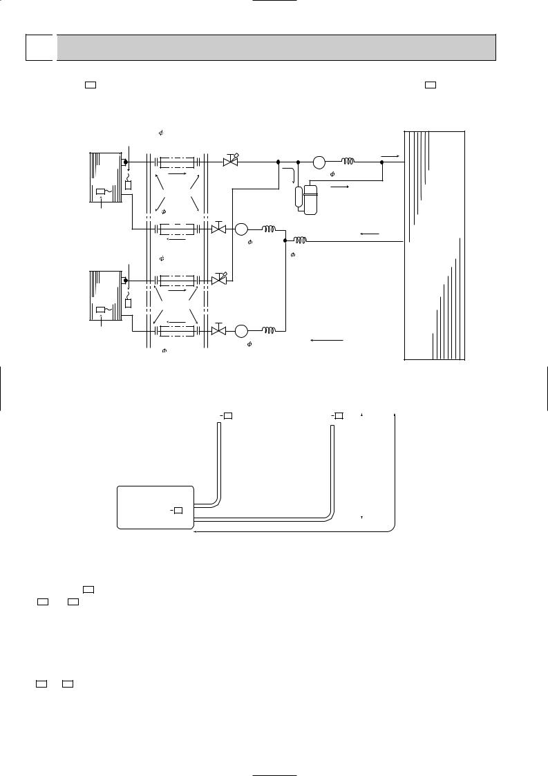
6 
 REFRIGERANT SYSTEM DIAGRAM
MSX-05NV- E1 |
MUX-10NV- E1 Unit : mm |
|||
|
|
|
|
|
|
INDOOR UNIT |
|
OUTDOOR UNIT |
|
UNIT A
UNIT B
Room |
Refrigerant pipe |
|
|
|
temperature |
9.52 (3/8) |
|
|
|
thermistor |
(option) |
|
Solenoid valve |
|
RT11 |
(With insulation) |
|
||
|
|
21R |
||
|
|
|
||
Indoor |
|
Stop valve |
Capillary tube |
|
heat |
|
with service port |
1.6 x 1,000 |
|
exchanger |
|
|
|
|
|
Flared connection |
|
|
|
|
Refrigerant pipe |
Solenoid valve |
|
|
Indoor coil |
6.35 (1/4) |
Compressor |
||
21R1 |
||||
thermistor |
(option) |
|
||
RT12 |
(With insulation) |
|
|
|
|
|
|
|
Stop |
Capillary tube |
|
Outdoor |
Room |
valve |
1.4 x 400 |
Capillary tube |
heat |
Refrigerant pipe |
|
exchanger |
||
temperature |
|
|||
|
1.4 x 200 |
|||
thermistor |
9.52 (3/8) |
|
|
|
|
|
|
||
RT11 |
(option) |
|
|
|
|
(With insulation) |
|
|
|
Indoor |
|
Stop valve |
|
||
heat |
|
|
|||
|
with service port |
|
|||
exchanger |
|
|
|||
Flared connection |
|
|
|
||
|
|
|
|
||
|
|
|
Solenoid valve |
|
|
|
|
|
21R2 |
|
|
Indoor coil |
|
|
|
|
|
thermistor |
|
Stop |
Capillary tube |
Refrigerant flow |
|
RT12 |
Refrigerant pipe |
valve |
1.4 x 400 |
||
|
|||||
|
6.35 (1/4) |
|
|
|
|
(option)
(With insulation)
MAX. REFRIGERANT PIPING LENGTH & MAX. HEIGHT DIFFERENCE
|
|
|
|
Indoor unit A |
|
|
|
|
|
Indoor unit B |
|
|
|
|
|
|
|
|
|
|
|
|
||||||
|
|
|
MSX-05NV |
E1 |
|
|
|
|
MSX-05NV |
|
E1 |
|
|
|
|
|
|
|
|
|
|
|
|
|||||
|
|
|
|
|
|
|
|
|
|
|
Max. length |
|
|
|
||||||||||||||
|
|
|
|
|
|
|
|
|
|
|
|
|
|
|||||||||||||||
|
|
|
|
|
|
|
|
|
|
|
|
|
|
|
|
|
|
|
|
|
|
|
||||||
|
|
|
|
|
|
|
|
|
|
|
|
|
|
|
|
|
|
|
|
|
|
|
||||||
|
|
|
|
|
|
|
|
|
|
|
|
|
|
|
|
|
|
|
|
difference |
|
|
|
|
|
|
||
|
|
|
|
|
|
|
|
|
|
|
|
|
|
|
|
|
|
|
|
5m |
|
|
|
|
|
|
||
|
Outdoor unit |
|
|
|
|
|
|
|
|
|
|
|
|
|
|
|
|
|
|
|
|
|
|
|
|
|
|
|
|
MUX-10NV |
E1 |
|
|
|
|
|
|
|
|
|
|
|
|
|
|
|
|
|
|
|
|
|
|
||||
|
|
|
|
|
|
Additional piping max. length 10m |
|
|
|
|
|
|
|
|
|
|
|
|
|
|
||||||||
|
|
|
|
|
|
|
|
|
|
|
|
|
|
|
|
|
|
|
|
|||||||||
|
|
|
|
|
|
|
|
|
|
|
|
|
|
|
|
|
|
|
|
|||||||||
|
|
|
|
|
|
|
|
|
|
|
|
|
|
|
|
|
|
|
|
|
|
|
|
|||||
ADDITIONAL REFRIGERANT CHARGE (R-22:g) |
|
|
|
|
|
|
|
|
|
|
|
|
|
|
|
|
|
|||||||||||
|
|
|
|
|
|
|
|
|
|
|
|
|
|
|
|
|
|
|
||||||||||
MSX-10NV- E1 |
Outdoor unit |
|
|
|
refrigerant piping length (one way,2unit total) |
|
|
|
|
|
|
|||||||||||||||||
precharged |
|
|
7m |
|
8m |
|
|
9m |
10m |
|
11m |
|
12m |
|
13m |
14m |
|
15m |
||||||||||
A unit+ B unit |
1150g |
|
0 |
|
10 |
|
|
20 |
30 |
|
|
40 |
|
|
|
50 |
|
60 |
70 |
|
80 |
|||||||
PIPING PREPARATION |
|
|
|
|
|
|
|
|
|
|
|
|
|
|
|
|
|
|
|
|
|
|
|
|
|
|
||
1 Table below shows the specifications of pipes commercially available. |
|
|
|
|
|
|
|
|
|
|
|
|
|
|
||||||||||||||
|
|
|
|
|
|
|
|
|
|
|
|
|
|
|
|
|
|
|
||||||||||
UNIT No. |
Pipe |
|
|
Outside diameter |
|
|
|
Insulation |
|
|
Insulation material |
|||||||||||||||||
|
|
mm |
|
|
|
|
inch |
|
|
thickness |
|
|
||||||||||||||||
|
|
|
|
|
|
|
|
|
|
|
|
|
|
|
|
|
|
|||||||||||
|
|
|
|
|
|
|
|
|
|
|
|
|
|
|
|
|
|
|
|
|||||||||
A and B UNIT |
For liquid |
|
6.35 |
|
|
1/4 |
|
|
|
|
6 mm |
|
|
|
Heat resisting foam plastic |
|||||||||||||
|
|
|
|
|
|
|
|
|
|
|
|
|
|
|
|
|
|
|
|
|
|
|
|
|
|
|
|
|
For gas |
|
9.52 |
|
|
3/8 |
|
|
|
|
6 mm |
|
|
|
0.045 specific gravity |
|
|||||||||||||
|
|
|
|
|
|
|
|
|
|
|
|
|||||||||||||||||
|
|
|
|
|
|
|
|
|
|
|
|
|
|
|
|
|
|
|
|
|
|
|
|
|
|
|
|
|
2 Ensure that the 2 refrigerant pipes are well insulated to prevent condensation. 3 Refrigerant bending radius must be 10cm or more.
14
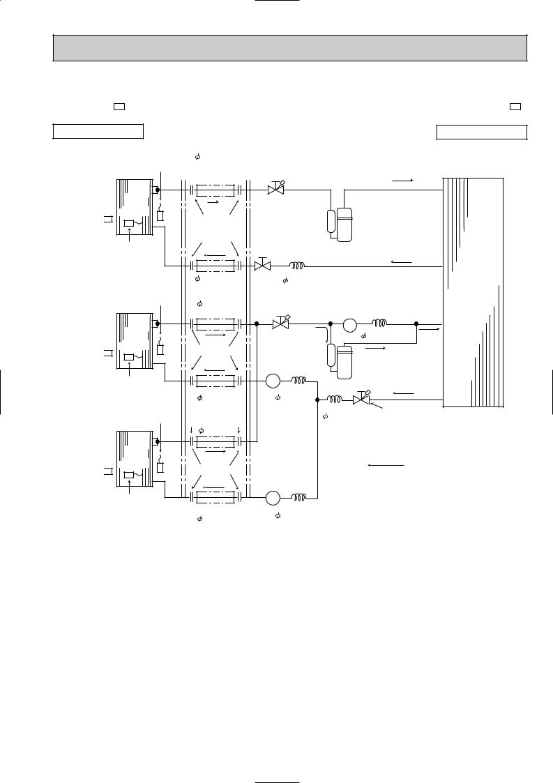
Unit : mm
MSX-09NV- E1
INDOOR UNIT
MUX-18NV- E1
OUTDOOR UNIT
UNIT A
MSX-09NV
 E1
E1
UNIT B
MSX-09NV
 E1
E1
UNIT C
MSX-09NV
 E1
E1
Room |
Refrigerant pipe |
|
|
|
|
temperature |
9.52<3/8> |
|
|
|
|
thermistor |
(option) |
|
|
|
|
(With insulation) |
|
|
|
||
RT11 |
|
|
|
||
|
|
|
|
||
Indoor |
|
Stop valve |
|
|
|
heat |
|
with service port |
|
|
|
exchanger |
|
|
|
|
|
|
Flared connection |
|
|
|
|
Indoor coil |
|
Stop valve |
Compressor(A) |
|
|
thermistor |
|
|
|
||
|
|
|
|
||
RT12 |
|
|
|
|
|
|
Refrigerant pipe |
Capillary tube |
|
|
|
|
6.35<1/4> |
1.4 1000 |
|
Outdoor |
|
Room |
(option) |
|
|||
|
|
heat |
|||
temperature |
(With insulation) |
|
|
||
Refrigerant pipe |
|
|
exchanger |
||
thermistor |
|
|
|||
9.52<3/8> |
|
|
|||
RT11 |
|
Solenoid valve |
|||
(option) |
|
21R |
|
||
|
(With insulation) |
|
|
||
Indoor |
|
Stop valve |
Capillary tube |
||
heat |
|
1.6 |
1,000 |
||
|
with |
||||
exchanger |
|
|
|
||
Flared connection |
service port |
|
|
||
|
|
|
|||
|
|
|
|
||
|
|
Solenoid valve |
|
|
|
|
|
21R1 |
|
|
|
Indoor coil |
|
|
Compressor(B,C) |
||
|
|
|
|
||
thermistor |
Refrigerant pipe |
Capillary tube |
|
|
|
RT12 |
|
|
|||
6.35<1/4> |
1.4 600 |
|
|
||
Room |
|
|
|||
(option) |
Capillary tube |
Stop valve |
|||
temperature |
|||||
(With insulation) |
with |
||||
|
1.4 150 |
||||
thermistor |
|
|
|||
|
|
service port |
|||
Refrigerant pipe |
|
|
|||
RT11 |
|
|
|||
|
|
|
|||
|
9.52<3/8> |
|
|
|
|
Indoor |
|
|
|
|
heat |
|
|
|
|
exchanger |
Flared connection |
|
Refrigerant flow |
|
|
Solenoid valve |
|||
|
|
|||
|
|
21R1 |
|
|
Indoor coil |
|
|
|
|
thermistor |
|
Capillary tube |
||
RT12 |
Refrigerant pipe |
|||
1.4 |
600 |
|||
|
6.35<1/4> |
|||
|
|
|
||
(option)
(With insulation)
15
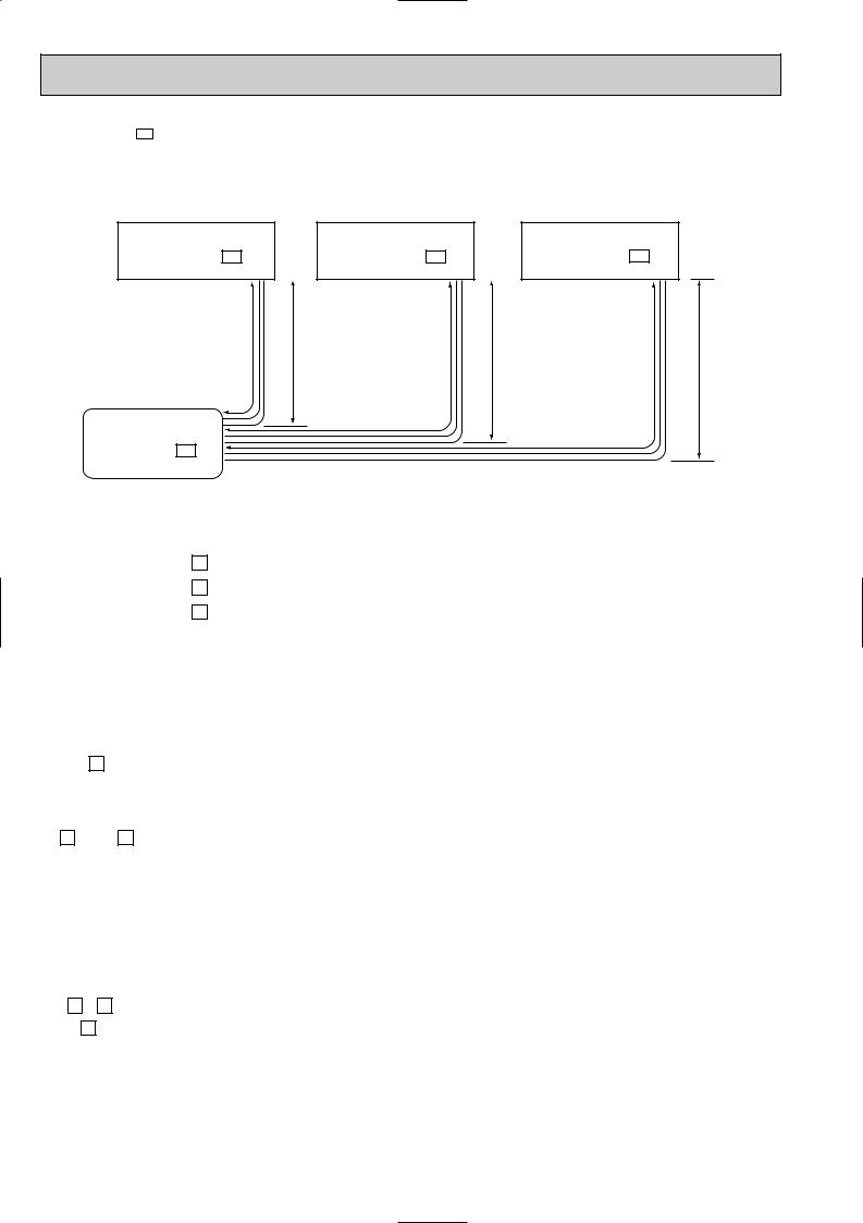
MSX-09NV- E1
MAX.REFRIGERANT PIPING LENGTH & MAX. HEIGHT DIFFERENCE
Indoor unit A |
|
Indoor unit B |
|
Indoor unit C |
MSX-09NV - E1 |
|
MSX-09NV - E1 |
|
MSX-09NV - E1 |
|
|
|
|
|
LA |
H |
LB |
H |
LC |
H
Outdoor unit
MUX-18NV - E1
|
UNIT No. |
|
Pipe length |
|
Height difference (H) |
No. of bends |
|||
|
|
|
|
|
|
|
|
|
|
Max. |
A |
LA |
|
10m |
|
5m |
|
10 |
|
|
|
|
|
|
|
|
|
||
B |
LB |
10m |
LB |
Total |
5m |
10 |
Total |
||
limits |
|||||||||
|
|
+ |
|
|
|||||
|
|
LC |
10m |
15m |
5m |
10 |
15 |
||
|
C |
LC |
|||||||
|
|
|
|||||||
|
|
|
|
|
|
|
|
|
|
Note: The length of piping to individual units (A,B,C) should not exceed 10 meters.
If units B and C are linked, the maximum combined length of piping should not exceed 15 meters.
ADDITIONAL REFRIGERANT CHARGE (R-22:g)
|
|
|
Outdoor unit |
|
|
|
|
|
Refrigerament piping length (one way) |
|
|
|
|||||||
|
|
|
|
|
|
|
|
|
|
|
|
|
|
|
|
|
|
|
|
|
A unit |
|
precharged |
|
7m |
|
|
|
8m |
|
|
9m |
|
|
|
10m |
|
||
|
|
|
|
|
|
|
|
|
|
|
|
|
|||||||
|
|
|
750g |
|
0 |
|
|
|
15 |
|
|
30 |
|
|
|
45 |
|
||
|
|
|
|
|
|
|
|
|
|
|
|
|
|
||||||
|
|
|
Outdoor unit |
|
|
|
Refrigerament piping length (one way,2 unit total) |
|
|
|
|||||||||
|
|
|
|
|
|
|
|
|
|
|
|
|
|
|
|
|
|
|
|
B |
unit + C |
unit |
precharged |
7m |
|
8m |
|
|
9m |
10m |
11m |
12m |
13m |
|
14m |
|
15m |
||
|
|
|
|
|
|
||||||||||||||
|
|
|
750g |
0 |
|
15 |
|
30 |
45 |
60 |
75 |
90 |
|
|
105 |
|
120 |
||
|
|
|
|
|
|
|
|
|
|
|
|
|
|
|
|
|
|
|
|
PIPING PREPARATION
1Table below shows the specifications of pipes commercially available.
UNIT No. |
Pipe |
Outside diameter |
Insulation |
Insulation material |
||
|
|
|||||
mm |
inch |
thickness |
||||
|
|
|
||||
|
|
|
|
|||
|
|
|
|
|
|
|
A , B and |
For liquid |
6.35 |
1/4 |
6mm |
Heat resisting foam plastic |
|
C unit |
For gas |
9.52 |
3/8 |
6mm |
0.045 specific gravity |
|
|
||||||
2Ensure that the 2 refrigerant pipes are well insulated to prevent condensation. 3Refrigerant bending radius must be 10cm or more.
16

|
|
|
|
|
MSX-09NV- E1 |
MUX-24NV- E1 Unit : mm |
|||
MSX-12NV- E1 |
|
|
|
|
|
|
|
|
|
|
INDOOR UNIT |
|
OUTDOOR UNIT |
|
UNIT A MSX-12NV- E1
UNIT B MSX-12NV- E1
UNIT C MSX-09NV- E1
UNIT D MSX-09NV- E1
Room |
Refrigerant pipe |
|
|
temperature |
{12.7 (1/2) |
|
|
thermistor |
(option) |
|
Solenoid valve |
RT11 |
(With insulation) |
|
|
|
|
21RA |
|
|
|
|
|
Indoor |
Stop valve |
Capillary tube |
|
heat |
with service port |
{1.6 x 1,000 |
|
exchanger |
|
|
|
|
Flared connection |
|
|
|
Refrigerant pipe |
Solenoid valve |
|
Indoor coil |
{6.35 (1/4) |
Compressor |
|
thermistor |
(option) |
21R1 |
|
(With insulation) |
|
|
|
RT12 |
|
|
|
|
|
|
|
|
Stop |
Capillary tube |
|
Room |
valve |
{1.6 x 400 |
Capillary tube |
Refrigerant pipe |
|
||
temperature |
|
||
|
{1.8 x 260 |
||
thermistor |
{12.7 (1/2) |
|
|
|
|
||
RT11 |
(option) |
|
|
(With insulation) |
|
|
|
|
|
|
|
Indoor |
|
Stop valve |
|
|
heat |
|
|
||
|
with service port |
|
||
exchanger |
|
|
||
Flared connection |
|
|
|
|
|
|
|
|
|
|
|
|
Solenoid valve |
|
|
|
|
21R2 |
|
Indoor coil |
|
|
|
|
thermistor |
|
Stop |
Capillary tube |
|
RT12 |
Refrigerant pipe |
valve |
{1.6 x 400 |
|
|
{6.35 (1/4) |
|
|
|
|
(option) |
|
|
|
|
(With insulation) |
|
|
Outdoor |
|
|
|
|
|
|
|
|
|
heat |
Room |
Refrigerant pipe |
|
|
exchanger |
temperature |
{9.52 (3/8) |
|
|
|
thermistor |
(option) |
|
|
Solenoid valve |
RT11 |
(With insulation) |
|
|
|
|
|
|
21RB |
|
|
|
|
|
|
Indoor |
|
Stop valve |
Capillary tube |
|
heat |
|
with service port |
{1.6 x 1,000 |
|
exchanger |
|
|
|
|
|
Flared connection |
|
|
|
|
Refrigerant pipe |
|
Solenoid valve |
|
Indoor coil |
{6.35 (1/4) |
|
Compressor |
|
thermistor |
(option) |
|
21R3 |
|
(With insulation) |
|
|
|
|
RT12 |
|
|
|
|
|
|
|
|
|
|
|
Stop |
Capillary tube |
|
Room |
|
valve |
{1.6 x 650 |
Capillary tube |
Refrigerant pipe |
|
|
||
temperature |
|
|
||
|
|
{1.6 x 400 |
||
thermistor |
{9.52 (3/8) |
|
|
|
|
|
|
||
RT11 |
(option) |
|
|
|
|
(With insulation) |
|
|
|
Indoor |
|
Stop valve |
|
|
heat |
|
|
||
|
with service port |
|
||
exchanger |
|
|
||
|
|
|
|
|
|
Flared connection |
|
|
|
|
|
|
Solenoid valve |
|
|
|
|
21R4 |
|
Indoor coil |
|
|
|
|
thermistor |
|
Stop |
Capillary tube |
Refrigerant flow |
RT12 |
Refrigerant pipe |
valve |
{1.6 x 650 |
|
|
{6.35 (1/4) |
|
|
|
(option)
(With insulation)
17
 Loading...