


MUZ-GB50VA-E1
SERVICE MANUAL
CONTENTS
1. TECHNICAL CHANGES ····································2
2. PART NAMES AND FUNCTIONS······················3
3. SPECIFICATION·················································3
4. NOISE CRITERIA CURVES·······························4
5. OUTLINES AND DIMENSIONS·························5
6. WIRING DIAGRAM ············································6
7. REFRIGERANT SYSTEM DIAGRAM················7
8. PERFORMANCE CURVES································9
9. ACTUA TOR CONTROL····································14
10. TROUBLESHOOTING ······································15
11. DISASSEMBLY INSTRUCTIONS·····················34
12. RoHS PARTS LIST···········································38
Wireless type
Models
MUZ-GB50VA -
MUZ-GB50VA -
E2
E1
SPLIT-TYPE, HEAT PUMP AIR CONDITIONERS
OUTDOOR UNIT
Indoor unit service manual
MSZ-GB·VA Series (OB454)
Refrigerant service manual
R410A REFRIGERANT (OBR01)
NOTE:
• This service manual describes technical data of the outdoor units.
HFC
utilized
R410A
Please void OB455 REVISED EDITION-C.
Revision D:
• RoHS PARTS LIST has been changed.
No. OB455
REVISED EDITION-D

2
1
TECHNICAL CHANGES
MUZ-GA50VA - ➔ MUZ- GB50VA -
E1E1
1. Refrigerant filling capacity has been changed.
2. Outdoor electronic control P.C. board has been changed.
Revision A:
• Compressor has been changed.
Previous
New
Model
SNB130FLDH
SNB130FLDH1
RoHS PARTS LIST number
E12 851 900
E12 939 900
Revision B:
• REFRIGERANT SYSTEM DIAGRAM has been changed.
• Oil separator has been added.
• Capillary tube has been added. ([1.8✕[0.6✕1000)
• MUZ-GB50VA- has been added.
• Check of outdoor thermistors(10-6.B) has been corrected.
E2
MUZ-GB50VA - ➔ MUZ- GB50VA -
E2E1
1. Compressor has been changed. (SNB130FLDH1 ➔ SNB130FLEH1)
2. Outdoor electronic control P.C. board has been changed.
Revision C:
• RoHS PARTS LIST has been changed.
Revision D:
• RoHS PARTS LIST has been changed.
3
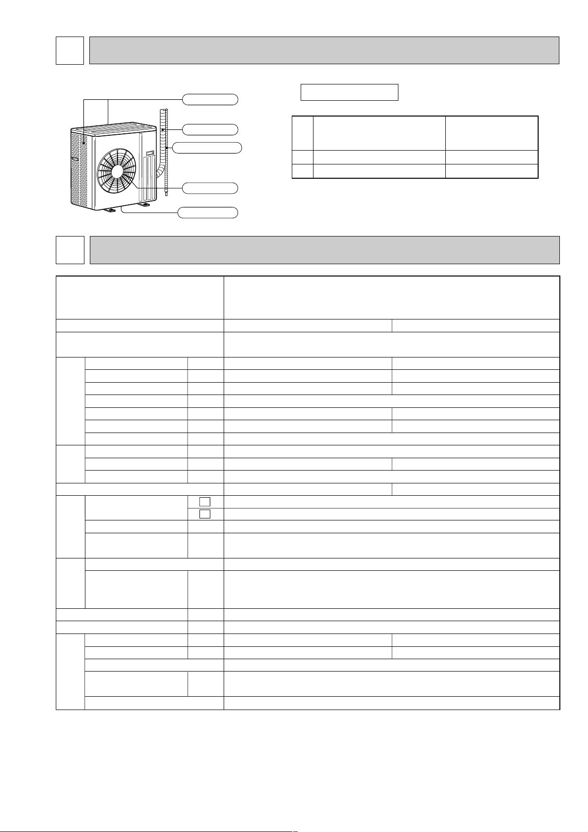
PART NAMES AND FUNCTIONS
2
3
SPECIFICATION
Air inlet
Piping
Air outlet
(back and side)
Drain hose
Drain outlet
MUZ-GB50VA
Outdoor model
Function
Power supply
Capacity Rated frequency(Min.-Max.)
Dehumidification
Air flow ✽1
(High/Low)
Power outlet
Running current ✽1
Power input ✽1
Power factor ✽1
Starting current ✽1
Compressor motor current ✽1
Fan motor current ✽1
Model
Output
Winding
resistance(at 20:)
Model
Winding
resistance(at 20:)
Dimensions WOHOD
Weight
Sound level ✽1
(High/Low)
Fan speed (High/Low)
Fan speed regulator
Refrigerant filling
capacity(R410A)
Refrigeration oil (Model)
kW
r/h
K /h
A
A
W
%
A
A
A
✽1
W
"
"
mm
kg
dB(A)
rpm
kg
Compressor
Fan
motor
Special
remarks
Capacity
Electrical
data
Coefficient of performance(C.O.P)
Single phase
230V,50Hz
20
97
7.46
0.32
SNB130FLDH or SNB130FLDH1
SNB130FLEH1
850
U-V 0.45 W-U 0.45
V-W 0.45
RC0J60-AA
BLK-WHT 15.2
WHT-RED 15.2
RED-BLK 15.2
840o850o330
53
2
1.50
NEO22
Cooling
5.0(0.9-5.8)
2.5
2,940/1,650
7.23
1,610
6.91
3.03
52/51
800/480
Heating
5.8(0.9-7.8)
—
2,940/2,210
7.43
1,660
7.11
3.41
55/53
800/620
MUZ-GB50VA
E1
E2
NOTE : Test conditions are based on ISO 5151.
Cooling : Indoor Dry-bulb temperature 27:Wet-bulb temperature 19:
Outdoor Dry-bulb temperature 35:Wet-bulb temperature 24:
Heating : Indoor Dry-bulb temperature 20:Wet-bulb temperature 15:
Outdoor Dry-bulb temperature 7: Wet-bulb temperature 6:
Refrigerant piping length (one way): 5m
✽1 Measured under rated operating frequency
ACCESSORIES
1
2
Drain socket
Drain cap [33
1
2
MUZ-GB50VA
4
4
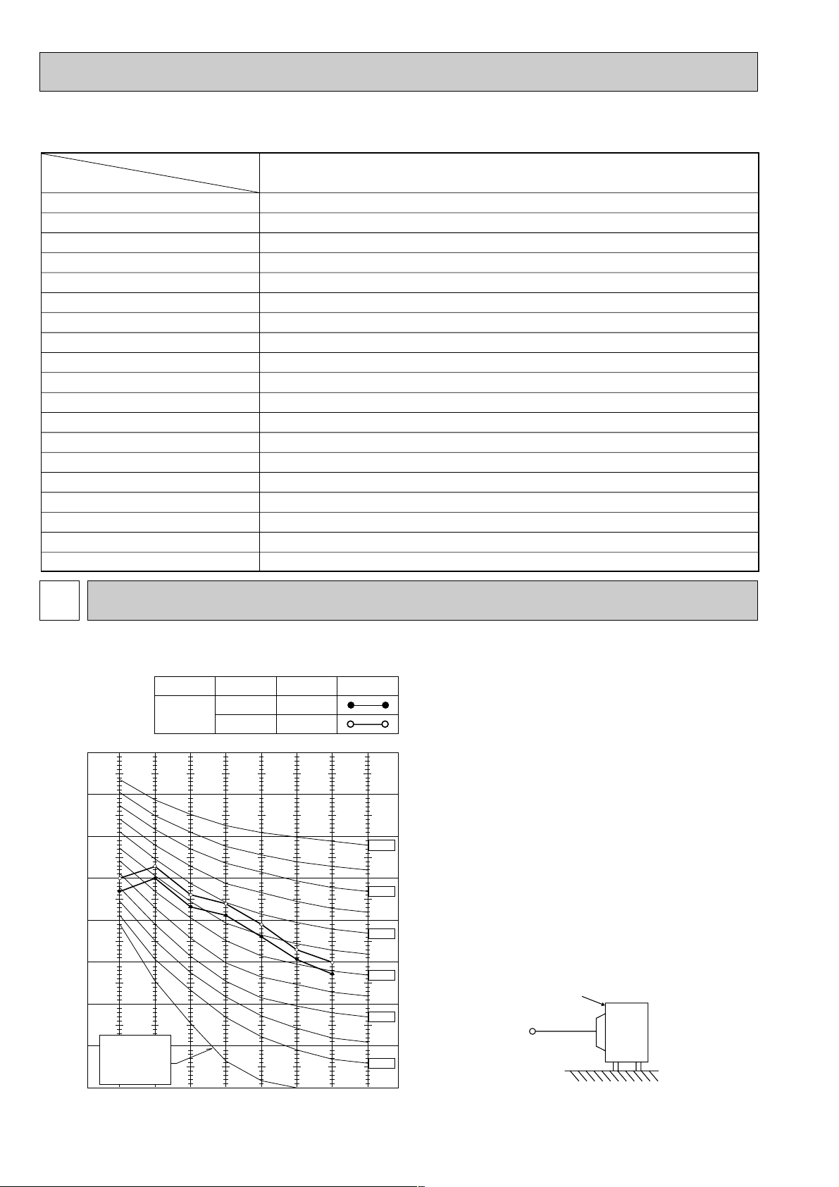
NOISE CRITERIA CURVES
OUTDOOR UNIT
MICROPHONE
1m
Test conditions
Cooling : Dry-bulb temperature 35:
Wet-bulb temperature (24:)
Heating : Dry-bulb temperature 7:
Wet-bulb temperature 6:
COOLING
FUNCTION
SPL(dB(A)) LINE
High
FAN SPEED
HEATING
52
55
90
80
70
60
50
40
30
20
10
63 125 250 500 1000 2000 4000 8000
NC-60
NC-50
NC-40
NC-30
NC-20
NC-70
BAND CENTER FREQUENCIES, Hz
APPROXIMATE
THRESHOLD OF
HEARING FOR
CONTINUOUS
NOISE
OCTAVE BAND SOUND PRESSURE LEVEL, 0dB=20µPa
MUZ-GB50VA
Specifications and rating conditions of main electric parts
Model
Item
Current transformer
Current transformer
Smoothing capacitor
Fuse
Fuse
Fuse
Expansion valve coil
Intelligent power module
Intelligent power module
Reactor
Power factor controller
Resistor
Resistor
Resistor
Solenoid coil relay
Terminal block
Terminal block
Relay
R.V. coil
MUZ-GB50VA
(CT1,2)
(CT61)
(CB1,2,3)
(F64)
(F801)
(F911)
(LEV)
(IPM)
(HC930)
(L)
(PFC)
(R64A,B)
(R937A,B)
(RS1~4)
(SSR61)
(TB1)
(TB2)
(X64)
(21S4)
ETQ19Z68AY
ETQ19Z53AY
560+ 450V
250V 2A
250V 3.15A
250V 1A
CAM-MD12ME
PS21244-A
PS21661-RZ
340µH 20A
PS51259-A
10
"
10W
1.1
"
2W 2%
0.04
"
7W
TLP3506
3P
3P
G4A
LD30013
5
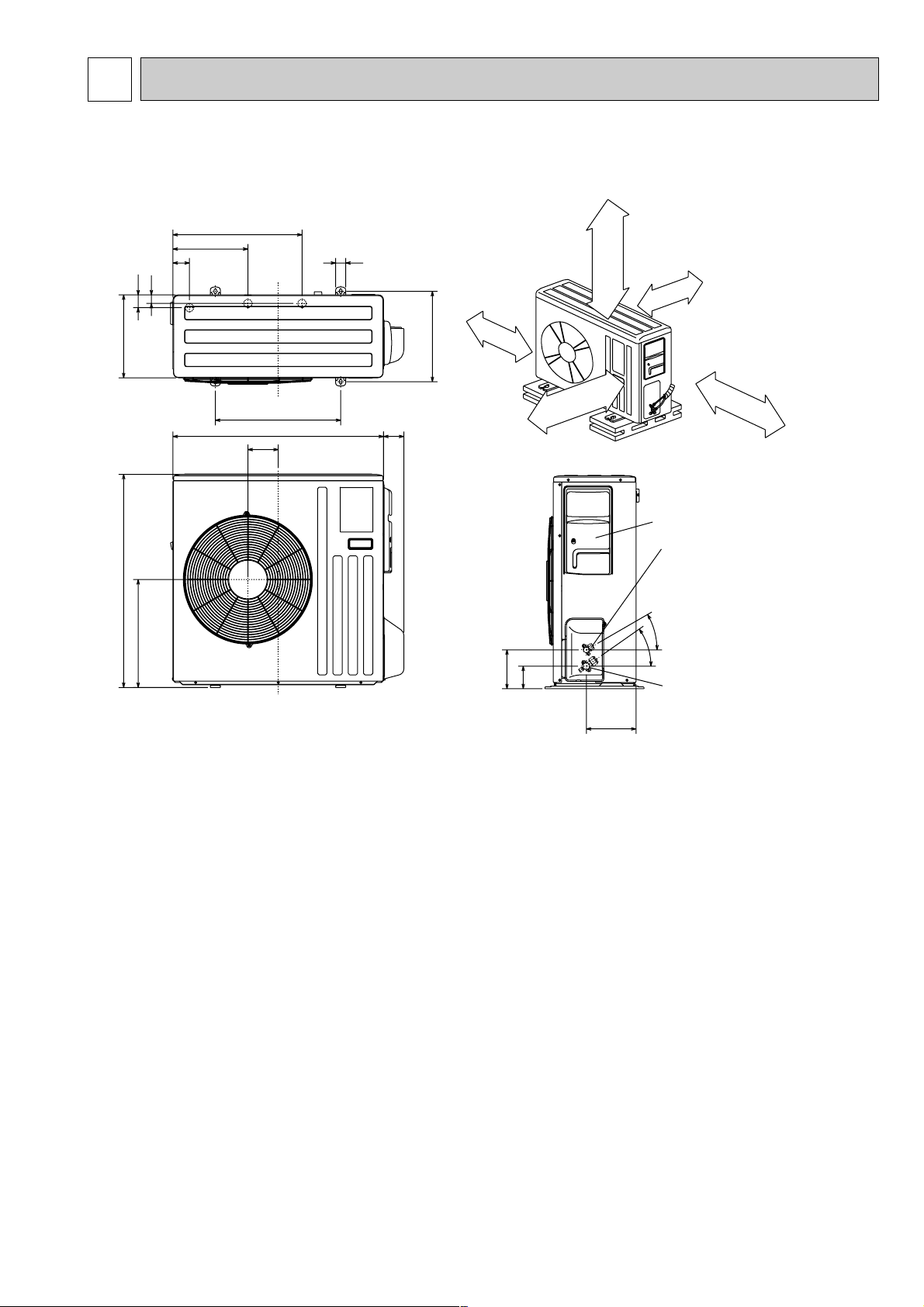
OUTLINES AND DIMENSIONS
5
Unit: mm
MUZ-GB50VA
30-
35-
155
90
198
40
515
299
66
34
51
330
360
850
430
500
80
121
840
Open as a rule
500 mm or more if
the front and both
sides are open
100 mm or more
200 mm or more if
there are obstacles
to both sides
Open as a rule
500 mm or more if the back,
both sides and top are open
350 mm or more
100 mm or more
Service panel
Gas refrigerant
pipe joint
Refrigerant pipe
(flared) [12.7
Liquid refrigerant
pipe joint
Refrigerant pipe
(flared) [6.35
REQUIRED SPACE
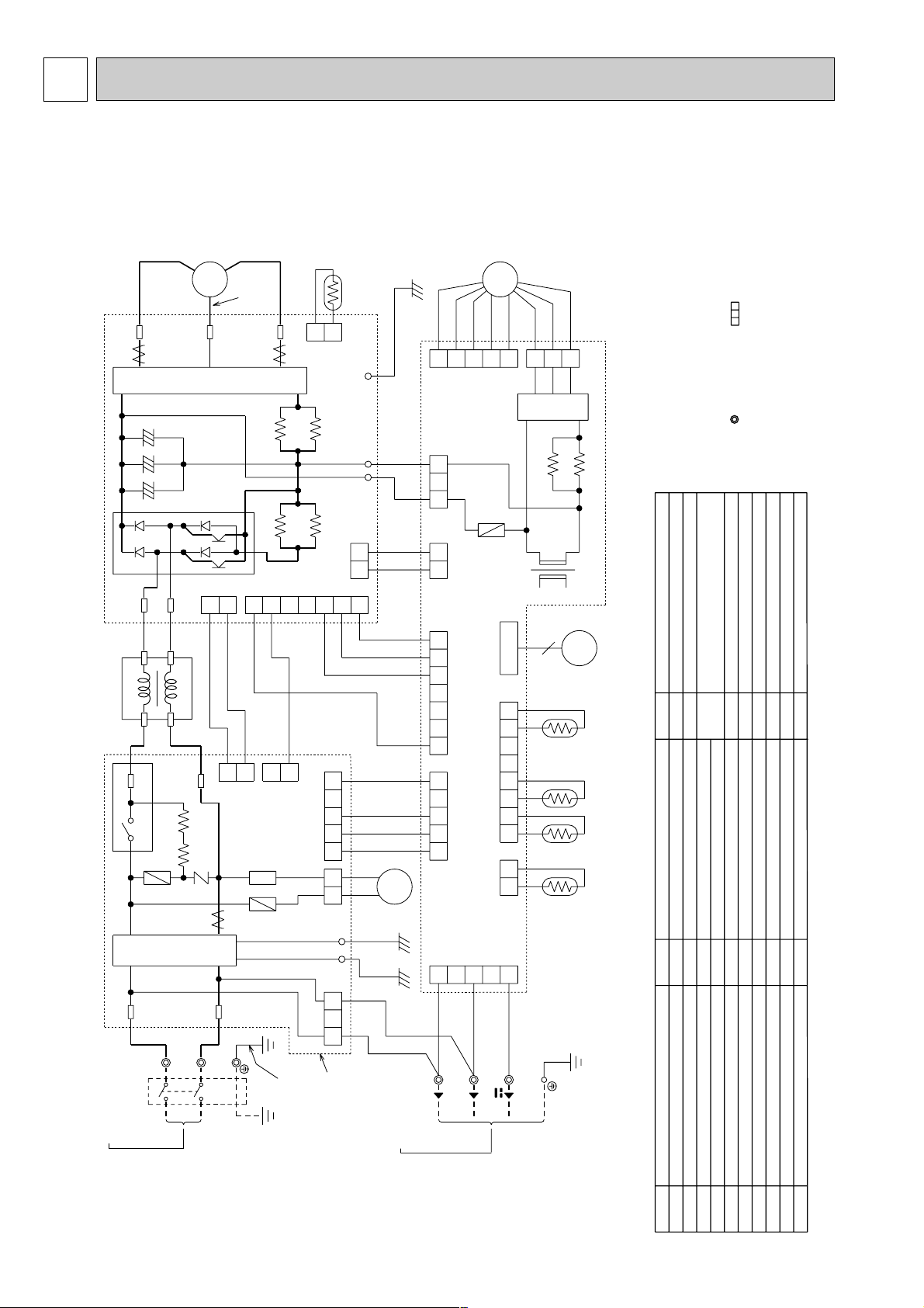
WIRING DIAGRAM
6
6
MUZ-GB50VA
R64B
YLW
230V~
12-24V
CN912
CN663
WHT
BLU
NOISE
FILTER
P.C.BOARD
BRN
TO INDOOR
UNIT
CONNECTING
RED
S3
RT65
21
CN61
13
GRN/YLW
5
PFC
GRN
LD9
POWER
BOARD
RT64
21
CN3
RED
WHT
RS2
RS1
R64A
RS3
RS4
F801
CN901
NR64
ELECTRONIC
CONTROL
P.C.BOARD
CB1
CB2
CB3
HC930
IPM
NF
BLK
BLK
BLK
BLK
WHT
RED
YLW
BLU
ORN
PNK
GRY
BLU
WHT
GRN
GRN
BLU
BLU
BLK
BLK
BLK
BLK
BLK
BLK
BLK
BLK
BLK
BLK
BLK
RED
BLU
L
CT2
CT1
SSR61
U
6
CN7954123 78
CN661
W
CN4
TB2
S1
1
CN601
3
S2
1567
CN702
5321
CN781
13
CN701
12
12
CN931
LD1LD2
T801
R937A
R937B
CN801
23134512
MF
CN932
3X64
5123
LDE2
12
CT61
TAB1
F64
F911
LDE1
21S4
POWER SUPPLY
~/N 230V 50Hz
TAB2
N
PE
L
TB1
CIRCUIT
BREAKER
4
1
RED
YLW
3
2
RED
S
R
21
CN903
21
CN902
21
CN5
6543 1
CN2
27
TAB4
V
MC
W
U
V
WHT
RT61 RT62 RT68
LEV
:Terminal block :Connector
3.Symbols below indicate.
2.Use copper conductors only (for field wiring).
diagram for servicing.
refer to the indoor unit electric wiring
1.About the indoor side electric wiringNOTES:
SYMBOL
NAME
SYMBOL
NAME
CURRENT TRANSFORMER
FUSE (T1AL 250V)
LEV
EXPANSION VALVE COIL
L
REACTOR
IPM
INTELLIGENT POWER MODULE
CT61
FUSE (T2AL 250V)
F64
CT1, 2
CURRENT TRANSFORMER
HC930
INTELLIGENT POWER MODULE
F911
F801
FUSE (T3.15AL 250V)
SMOOTHING CAPACITOR
CB1~3
OUTDOOR FAN MOTOR
POWER FACTOR CONTROLLER
NOISE FILTER
RT61
DISCHARGE TEMPERATURE THERMISTOR
RS1~4
RESISTOR
R937A, B
RESISTOR
MF
MC
COMPRESSOR
R64A,B
RESISTOR
PFC
NF
NR64
VARISTOR
AMBIENT TEMPERATURE THERMISTOR
SOLENOID COIL RELAY
21S4
R.V. COIL
X64
RELAY
TB1
TERMINAL BLOCK
TB2
TERMINAL BLOCK
RT65
FIN TEMPERATURE THERMISTOR
RT64
T801
TRANSFORMER
SSR61
RT68
OUTDOOR HEAT EXCHANGER
TEMPERATURE THERMISTOR
DEFROST THERMISTOR
RT62
NAME
SYMBOL
7
7
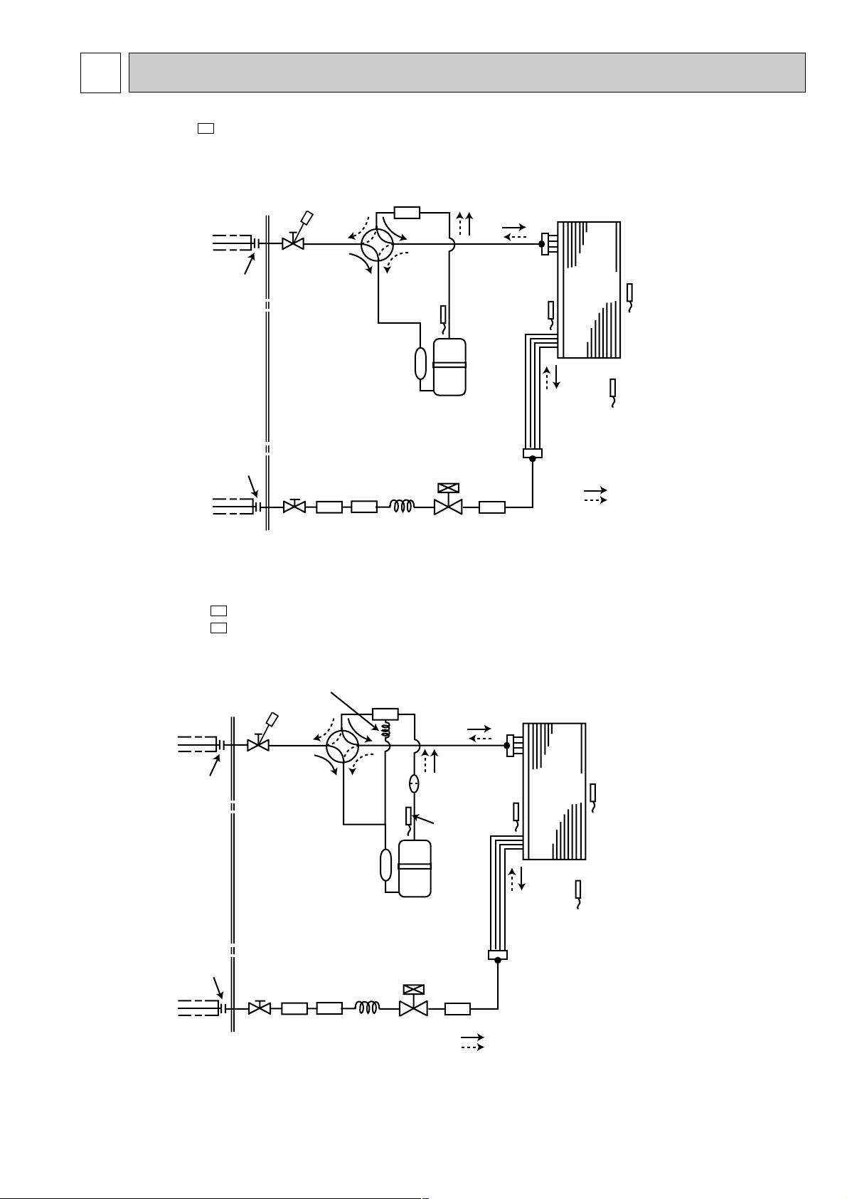
REFRIGERANT SYSTEM DIAGRAM
MUZ-GB50VA-
E1
Unit:mm
Outdoor
heat
exchanger
Flared connection
Defrost
thermistor
RT61
Discharge
temperature
thermistor
RT62
Flared connection
Stop valve
Stop valve
(with service port)
Capillary tube
[3.6✕[2.4✕50
Refrigerant flow in cooling
Compressor
4-way valve
Refrigerant flow in heating
Refrigerant pipe [12.7
(with heat insulator)
Refrigerant pipe [6.35
(with heat insulator)
LEV
R.V. coil
OFF
ON
Muffler
#100
Strainer
#100
Receiver
Outdoor heat
exchanger
temperature
thermistor
RT68
Ambient
temperature
thermistor
RT65
Strainer
#100
MUZ-GB50VA-
MUZ-GB50VA-
E2
E1
Unit:mm
Outdoor
heat
exchanger
Flared connection
Defrost
thermistor
RT61
Discharge
temperature
thermistor
RT62
Flared connection
Stop valve
Stop valve
(with service port)
Capillary tube
[3.6✕[2.4✕50
Capillary tube
[1.8✕[0.6✕1000
Refrigerant flow in cooling
Compressor
4-way valve
Refrigerant flow in heating
Refrigerant pipe [12.7
(with heat insulator)
Refrigerant pipe [6.35
(with heat insulator)
LEV
R.V. coil
heating ON
cooling OFF
Oil separator
Strainer
#100
Receiver
Outdoor
heat
exchanger
temperature
thermistor
RT68
Strainer
#100
Strainer
#100
Ambient
temperature
thermistor
RT65
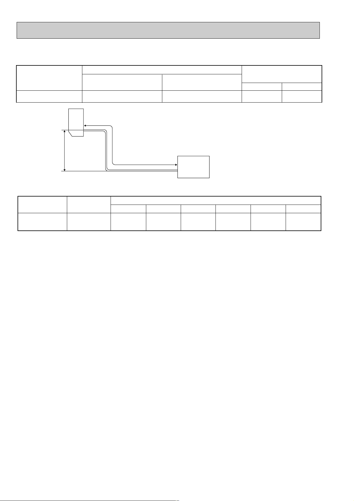
8
ADDITIONAL REFRIGERANT CHARGE (R410A:g)
Max. length
A
Max. Height
difference
B
Indoor
unit
Outdoor unit
MAX. REFRIGERANT PIPING LENGTH and MAX. HEIGHT DIFFERENCE
Max. length
A
30
Max. Height difference
B
15
Model
Gas
12.7
Liquid
6.35
Piping size O.D : mm
Refrigerant piping : m
MUZ-GB50VA
Model
MUZ-GB50VA
Refrigerant piping length (one way)
Outdoor unit
precharged
1,500
15m
160
20m
260
25m
360
30m
460
7m
0
10m
60
Calculation : Xg=20g/m ✕ (Refrigerant piping length (m)–7)
NOTE : Refrigerant piping exceeding 7m requires additional refrigerant charge according to the calculation.
9
PERFORMANCE CURVES8
The standard specifications apply only to the operation of the air conditioner under normal conditions. Since operating condi-
tions vary according to the areas where these units are installed, the following information has been provided to clarify the
operating characteristics of the air conditioner under the conditions indicated by the performance curve.
(1) GUARANTEED VOLTAGE
198 ~ 264V, 50Hz
(2) AIR FLOW
Air flow should be set at MAX.
(3) MAIN READINGS
(1) Indoor intake air wet-bulb temperature : °C [WB]
(2) Indoor outlet air wet-bulb temperature : °C [WB]
(3) Outdoor intake air dry-bulb temperature : °C [DB]
(4) Total input: W
(5) Indoor intake air dry-bulb temperature : °C [DB]
(6) Outdoor intake air wet-bulb temperature : °C [WB]
(7) Total input : W
Indoor air wet/dry-bulb temperature difference on the left side of the following chart shows the difference between the
indoor intake air wet/dry-bulb temperature and the indoor outlet air wet/dry-bulb temperature for your reference at service.
}
}
Cooling
Heating
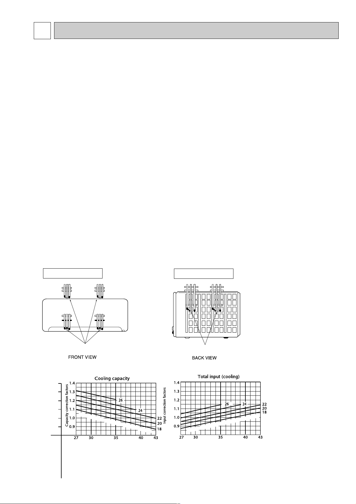
How to measure the indoor air wet-bulb / dry-bulb temperature difference
1. Attach at least 2 sets of wet and dry-bulb thermometers to the indoor air intake as shown in the figure, and at least 2 sets
of wet and dry-bulb thermometers to the indoor air outlet. The thermometers must be attached to the position where air
speed is high.
2. Attach at least 2 sets of wet and dry-bulb thermometers to the outdoor air intake.
Cover the thermometers to prevent direct rays of the sun.
3. Check that the air filter is cleaned.
4. Open windows and doors of room.
5. Press the EMERGENCY OPERATION switch once (twice) to start the EMERGENCY COOL (HEAT) MODE.
6. When system stabilizes after more than 15 minutes, measure temperature and take an average temperature.
7. 10 minutes later, measure temperature again and check that the temperature does not change.
MUZ-GB50VA
INDOOR UNIT
OUTDOOR UNIT
Wet and dry-bulb
thermometers
Wet and dry-bulb
thermometers
Indoor air Wet-bulb temperature
difference (:)
MSZ-GB50VA
8.7
8.0
7.3
6.6
5.9
5.3
at Rated frequency
Outdoor intake air Dry-bulb temperature (:)
Outdoor intake air Dry-bulb temperature (:)
Indoor intake air Wet-bulb temperature (
:)
Indoor intake air W
et-bulb tem
perature (
:
)
MUZ-GB50VA
8-1. Capacity and input curves
10
Indoor air Dry-bulb temperature
difference (
:)
Indoor intake air Dry-bulb tem
perature (
:
)
Outdoor intake air Wet-bulb temperature (:)
Outdoor intake air Wet-bulb temperature (:)
Indoor intake air Dry-bulb temperature (
:)
24.1
22.3
20.4
18.5
16.7
14.8
13.0
11.1
at Rated frequency
MUZ-GB50VA
MSZ-GB50VA
NOTE:The above broken lines are for the heating operation without any
frost and defrost operation.
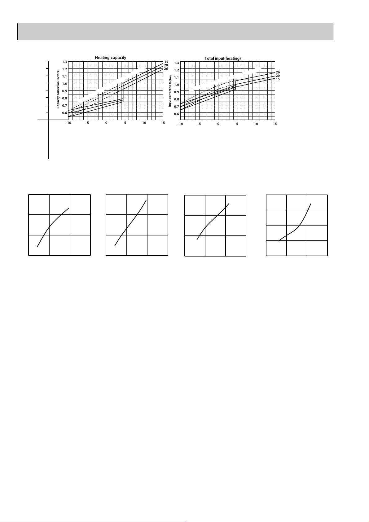
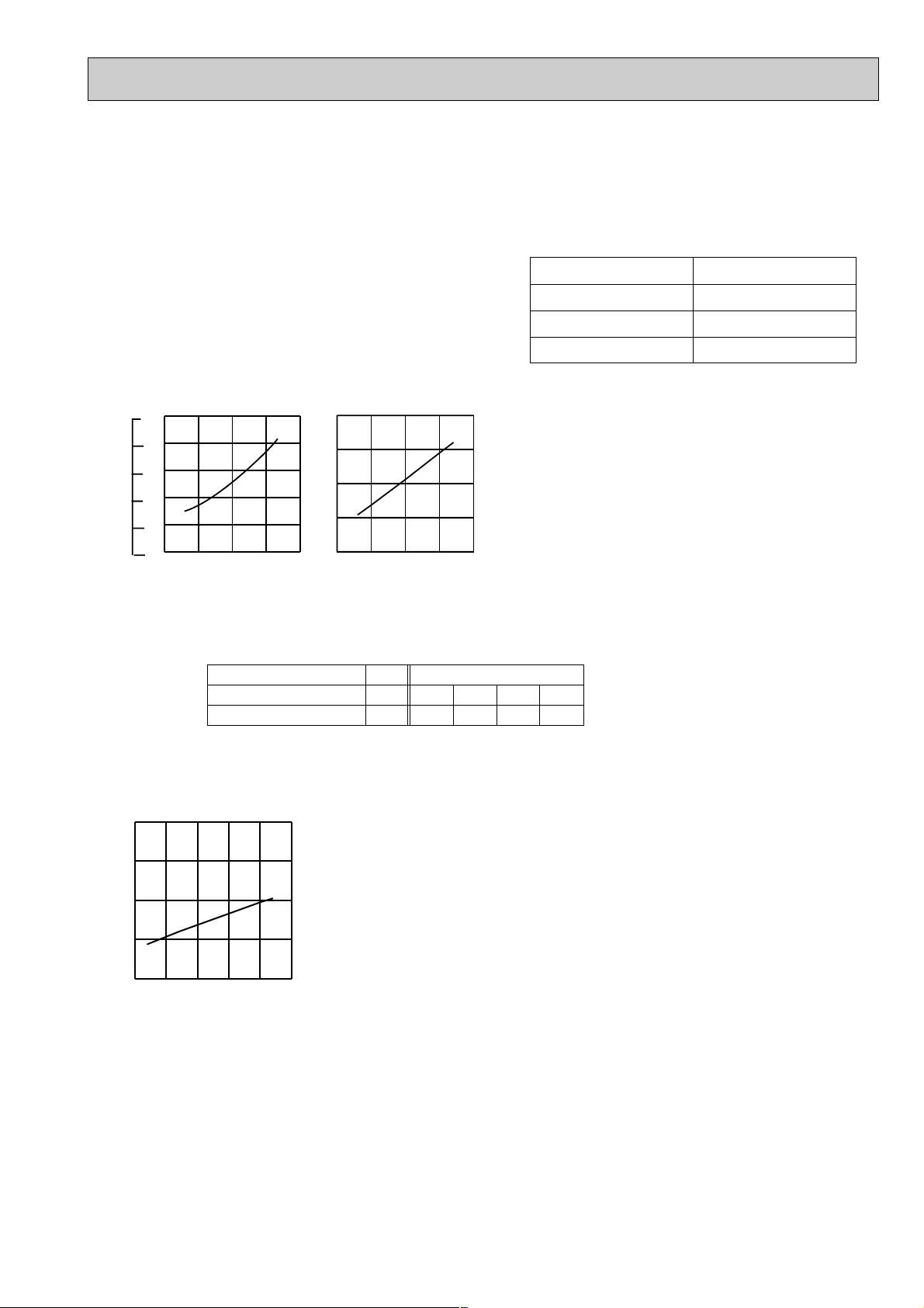
8-2. Capacity and input correction by operational frequency of compressor
Capacity correction factors
Input correction factors
Input correction factors
Capacity correction factors
Correction of Cooling capacity
The operational frequency of compressor
Correction of Cooling total input
The operational frequency of compressor
Correction of Heating total input
The operational frequency of compressor
Correction of Heating capacity
The operational frequency of compressor
MUZ-GB50VA
(Hz)
0 50 100 150
0.0
0.5
1.0
1.5
(Hz)
(Hz)
(Hz)
0 50 100 150
0.0
0.5
1.0
1.5
0 50 100 150
0.0
0.5
1.0
1.5
0 50 100 150
0.0
0.5
1.0
1.5
0 50 100 150
0.0
0.5
1.0
1.5
2.0
1. Press EMERGENCY OPERATION switch to COOL or HEAT mode (COOL : Press once, HEAT : Press twice).
2. Test run operation starts and continues to operate for 30 minutes.
3. Compressor operates at rated frequency in COOL mode or 58Hz in HEAT mode.
4. Indoor fan operates at High speed.
5. After 30 minutes, test run operation finishes and EMERGENCY OPERATION starts (Operation frequency of compressor
varies).
6. To cancel test run operation (EMERGENCY OPERATION), press EMERGENCY OPERATION switch or any button on
remote controller.
8-3. Test run operation (How to operate fixed-frequency operation)
11
COOL operation
1 Both indoor and outdoor unit are under the
same temperature/humidity condition.
2 Operation : TEST RUN OPERATION (refer to 8-3.)
Dry-bulb temperature(:)
Relative humidity(%)
20
50
25
60
30 70
8-4. OUTDOOR LOW PRESSURE AND OUTDOOR UNIT CURRENT
Ambient temperature(˚C)
Ambient humidity(%)
18 32
15 20
50
25
60
30
70 (%)
35(˚C)
Ambient temperature(˚C)
Ambient humidity(%)
18 32
15 20
50
25
60
30
70 (%)
35(˚C)
MUZ-GB50VA
(MPa [Gauge])
(kgf/F [Gauge])
Outdoor low pressure
Outdoor unit current(A)
4
5
6
7
8
0.5
0.6
0.7
0.8
0.9
1.0
5
6
7
8
9
10
1 Condition :
2 Operation : TEST RUN OPERATION (refer to 8-3.)
HEAT operation
Dry bulb temperature (°C)
Indoor
20.0
14.5
2
1
Outdoor
7
6
15
12
20.0
14.5
Wet bulb temperature (°C)
0 5 10 15 20 25(˚C)
4
5
6
7
8
Outdoor unit current (A)
Ambient temperature(˚C)
MUZ-GB50VA
2
NOTE: The unit of pressure has been changed to MPa based on the international system of units (SI unit system).
The conversion factor is: 1(MPa [Gauge] = 10.2 (Kgf/
ff
[Gauge])

12
MSZ-GB50VA : MUZ-GB50VA
21 18 5.88 3.00 0.51 1320 5.63 2.87 0.51 1386 5.40 2.75 0.51 1452 5.20 2.65 0.51 1518
21 20 6.13 2.39 0.39 1386 5.88 2.29 0.39 1469 5.70 2.22 0.39 1502 5.50 2.15 0.39 1568
22 18 5.88 3.23 0.55 1320 5.63 3.09 0.55 1386 5.40 2.97 0.55 1452 5.20 2.86 0.55 1518
22 20 6.13 2.63 0.43 1386 5.88 2.53 0.43 1469 5.70 2.45 0.43 1502 5.50 2.37 0.43 1568
22 22 6.38 1.98 0.31 1436 6.15 1.91 0.31 1526 6.00 1.86 0.31 1568 5.75 1.78 0.31 1634
23 18 5.88 3.47 0.59 1320 5.63 3.32 0.59 1386 5.40 3.19 0.59 1452 5.20 3.07 0.59 1518
23 20 6.13 2.88 0.47 1386 5.88 2.76 0.47 1469 5.70 2.68 0.47 1502 5.50 2.59 0.47 1568
23 22 6.38 2.23 0.35 1436 6.15 2.15 0.35 1526 6.00 2.10 0.35 1568 5.75 2.01 0.35 1634
24 18 5.88 3.70 0.63 1320 5.63 3.54 0.63 1386 5.40 3.40 0.63 1452 5.20 3.28 0.63 1518
24 20 6.13 3.12 0.51 1386 5.88 3.00 0.51 1469 5.70 2.91 0.51 1502 5.50 2.81 0.51 1568
24 22 6.38 2.49 0.39 1436 6.15 2.40 0.39 1526 6.00 2.34 0.39 1568 5.75 2.24 0.39 1634
24 24 6.70 1.81 0.27 1502 6.45 1.74 0.27 1584 6.30 1.70 0.27 1634 6.10 1.65 0.27 1716
25 18 5.88 3.94 0.67 1320 5.63 3.77 0.67 1386 5.40 3.62 0.67 1452 5.20 3.48 0.67 1518
25 20 6.13 3.37 0.55 1386 5.88 3.23 0.55 1469 5.70 3.14 0.55 1502 5.50 3.03 0.55 1568
25 22 6.38 2.74 0.43 1436 6.15 2.64 0.43 1526 6.00 2.58 0.43 1568 5.75 2.47 0.43 1634
25 24 6.70 2.08 0.31 1502 6.45 2.00 0.31 1584 6.30 1.95 0.31 1634 6.10 1.89 0.31 1716
26 18 5.88 4.17 0.71 1320 5.63 3.99 0.71 1386 5.40 3.83 0.71 1452 5.20 3.69 0.71 1518
26 20 6.13 3.61 0.59 1386 5.88 3.47 0.59 1469 5.70 3.36 0.59 1502 5.50 3.25 0.59 1568
26 22 6.38 3.00 0.47 1436 6.15 2.89 0.47 1526 6.00 2.82 0.47 1568 5.75 2.70 0.47 1634
26 24 6.70 2.35 0.35 1502 6.45 2.26 0.35 1584 6.30 2.21 0.35 1634 6.10 2.14 0.35 1716
26 26 6.90 1.59 0.23 1584 6.70 1.54 0.23 1667 6.60 1.52 0.23 1716 6.40 1.47 0.23 1766
27 18 5.88 4.41 0.75 1320 5.63 4.22 0.75 1386 5.40 4.05 0.75 1452 5.20 3.90 0.75 1518
27 20 6.13 3.86 0.63 1386 5.88 3.70 0.63 1469 5.70 3.59 0.63 1502 5.50 3.47 0.63 1568
27 22 6.38 3.25 0.51 1436 6.15 3.14 0.51 1526 6.00 3.06 0.51 1568 5.75 2.93 0.51 1634
27 24 6.70 2.61 0.39 1502 6.45 2.52 0.39 1584 6.30 2.46 0.39 1634 6.10 2.38 0.39 1716
27 26 6.90 1.86 0.27 1584 6.70 1.81 0.27 1667 6.60 1.78 0.27 1716 6.40 1.73 0.27 1766
28 18 5.88 4.64 0.79 1320 5.63 4.44 0.79 1386 5.40 4.27 0.79 1452 5.20 4.11 0.79 1518
28 20 6.13 4.10 0.67 1386 5.88 3.94 0.67 1469 5.70 3.82 0.67 1502 5.50 3.69 0.67 1568
28 22 6.38 3.51 0.55 1436 6.15 3.38 0.55 1526 6.00 3.30 0.55 1568 5.75 3.16 0.55 1634
28 24 6.70 2.88 0.43 1502 6.45 2.77 0.43 1584 6.30 2.71 0.43 1634 6.10 2.62 0.43 1716
28 26 6.90 2.14 0.31 1584 6.70 2.08 0.31 1667 6.60 2.05 0.31 1716 6.40 1.98 0.31 1766
29 18 5.88 4.88 0.83 1320 5.63 4.67 0.83 1386 5.40 4.48 0.83 1452 5.20 4.32 0.83 1518
29 20 6.13 4.35 0.71 1386 5.88 4.17 0.71 1469 5.70 4.05 0.71 1502 5.50 3.91 0.71 1568
29 22 6.38 3.76 0.59 1436 6.15 3.63 0.59 1526 6.00 3.54 0.59 1568 5.75 3.39 0.59 1634
29 24 6.70 3.15 0.47 1502 6.45 3.03 0.47 1584 6.30 2.96 0.47 1634 6.10 2.87 0.47 1716
29 26 6.90 2.42 0.35 1584 6.70 2.35 0.35 1667 6.60 2.31 0.35 1716 6.40 2.24 0.35 1766
30 18 5.88 5.11 0.87 1320 5.63 4.89 0.87 1386 5.40 4.70 0.87 1452 5.20 4.52 0.87 1518
30 20 6.13 4.59 0.75 1386 5.88 4.41 0.75 1469 5.70 4.28 0.75 1502 5.50 4.13 0.75 1568
30 22 6.38 4.02 0.63 1436 6.15 3.87 0.63 1526 6.00 3.78 0.63 1568 5.75 3.62 0.63 1634
30 24 6.70 3.42 0.51 1502 6.45 3.29 0.51 1584 6.30 3.21 0.51 1634 6.10 3.11 0.51 1716
30 26 6.90 2.69 0.39 1584 6.70 2.61 0.39 1667 6.60 2.57 0.39 1716 6.40 2.50 0.39 1766
31 18 5.88 5.35 0.91 1320 5.63 5.12 0.91 1386 5.40 4.91 0.91 1452 5.20 4.73 0.91 1518
31 20 6.13 4.84 0.79 1386 5.88 4.64 0.79 1469 5.70 4.50 0.79 1502 5.50 4.35 0.79 1568
31 22 6.38 4.27 0.67 1436 6.15 4.12 0.67 1526 6.00 4.02 0.67 1568 5.75 3.85 0.67 1634
31 24 6.70 3.69 0.55 1502 6.45 3.55 0.55 1584 6.30 3.47 0.55 1634 6.10 3.36 0.55 1716
31 26 6.90 2.97 0.43 1584 6.70 2.88 0.43 1667 6.60 2.84 0.43 1716 6.40 2.75 0.43 1766
32 18 5.88 5.58 0.95 1320 5.63 5.34 0.95 1386 5.40 5.13 0.95 1452 5.20 4.94 0.95 1518
32 20 6.13 5.08 0.83 1386 5.88 4.88 0.83 1469 5.70 4.73 0.83 1502 5.50 4.57 0.83 1568
32 22 6.38 4.53 0.71 1436 6.15 4.37 0.71 1526 6.00 4.26 0.71 1568 5.75 4.08 0.71 1634
32 24 6.70 3.95 0.59 1502 6.45 3.81 0.59 1584 6.30 3.72 0.59 1634 6.10 3.60 0.59 1716
32 26 6.90 3.24 0.47 1584 6.70 3.15 0.47 1667 6.60 3.10 0.47 1716 6.40 3.01 0.47 1766
INDOOR INDOOR
CAPACITY:5.0(kW)
INPUT:1650(W)SHF:0.69
21
OUTDOOR DB(
:
)
25 27 30
WB(:)
Q SHC SHF Q SHC SHF Q SHC SHF Q SHC SHFINPUT INPUT INPUT INPUT
DB(:)
PERFORMANCE DATA COOL operation at Rated frequency
NOTE Q : Total capacity (kW) SHF : Sensible heat factor DB : Dry-bulb temperature
SHC : Sensible heat capacity (kW) INPUT : Total power input (W) WB : Wet-bulb temperature
 Loading...