


Revision A:
FLOOR AND CEILING TYPE AIR CONDITIONERS
● Power input of SPECIFICATION has modified.
Please void OB337.
|
HFC |
No. OB337 |
|
REVISED EDITION-A |
|
|
utilized |
|
SERVICE MANUAL |
R410A |
|
|
|
|
|
|
|
|
|
|
Wireless type |
|
|
Models |
|
|
MUCFH-A18WV - E1 |
|
|
MUCFH-A24WV - E1 |
|
|
CONTENTS
1.TECHNICAL CHANGES ················
2.PART NAMES AND FUNCTIONS············
3.SPECIFICATION····················
4.NOISE CRITERIA CURVES ···············
5.OUTLINES AND DIMENSIONS ·············
6.WIRING DIAGRAM ··················
7.REFRIGERANT SYSTEM DIAGRAM ···········
8. PERFORMANCE CURVES ···············
Indication of model name 9. ACTUATOR CONTROL·················
MUCFH-A18WV - E1 10. SERVICE FUNCTIONS·················
11.TROUBLESHOOTING ·················
12.DISASSEMBLY INSTRUCTIONS·············
13.PARTS LIST······················
NOTE:
•This service manual describes technical data of outdoor units.
As for indoor units MCFH-A18WV- E1 and MCFH-A24WV- E1 refer to the service manual OB336 REVISED EDITION-A.

Revision A:
•Power input of SPECIFICATION has modified.
1 
 TECHNICAL CHANGES
MUH-A18WV - E1 MUCFH-A18WV - E1
1.Capillary tube has changed.
2.Refrigerant filling capacity has changed. (1.75kg 1.85kg)
MUH-A24WV - E1 MUCFH-A24WV - E1
1.Capillary tube has changed.
2.Refrigerant filling capacity has changed. (2.15kg 2.20kg)
INFORMATION FOR THE AIR CONDITIONER WITH R410A REFRIGERANT
•This room air conditioner adopts an HFC refrigerant (R410A) which never destroys the ozone layer.
•Pay particular attention to the following points, though the basic installation procedure is same as that for R22 conditioners.
1As R410A has working pressure approximate 1.6 times as high as that of R22, some special tools and piping parts/ materials are required. Refer to the table below.
2Take sufficient care not to allow water and other contaminations to enter the R410A refrigerant during storage and installation, since it is more susceptible to contaminations than R22.
3For refrigerant piping, use clean, pressure-proof parts/materials specifically designed for R410A. (Refer to 2. Refrigerant piping.)
4Composition change may occur in R410A since it is a mixed refrigerant. When charging, charge liquid refrigerant to prevent composition change.
Refrigerant
Refrigerating |
oil |
|
New refrigerant |
Previous refrigerant |
Refrigerant |
R410A |
R22 |
|
|
|
Composition (Ratio) |
HFC-32: HFC-125 (50%:50%) |
R22 (100%) |
|
|
|
Refrigerant handling |
Pseudo-azeotropic refrigerant |
Single refrigerant |
|
|
|
Chlorine |
Not included |
Included |
|
|
|
Safety group (ASHRAE) |
A1/A1 |
A1 |
|
|
|
Molecular weight |
72.6 |
86.5 |
|
|
|
Boiling point (:) |
-51.4 |
-40.8 |
Steam pressure [25:](Mpa) |
1.557 |
0.94 |
Saturated steam density [25:](Kg/K) |
64 |
44.4 |
Combustibility |
Non combustible |
Non combustible |
|
|
|
ODP w1 |
0 |
0.055 |
|
|
|
GWP w2 |
1730 |
1700 |
|
|
|
Refrigerant charge method |
From liquid phase in cylinder |
Gas phase |
|
|
|
Additional charge on leakage |
Possible |
Possible |
Kind |
Incompatible oil |
Compatible oil |
|
|
|
Color |
Non |
Light yellow |
|
|
|
Smell |
Non |
Non |
|
|
|
w1 :Ozone Destruction Parameter |
: based on CFC-11 |
w2 :Global Warmth Parameter |
: based on CO2 |
2
|
|
|
|
|
|
|
|
|
|
|
|
|
|
|
|
|
|
|
|
|
|
|
|
|
|
|
|
|
|
|
|
|
|
|
|
|
|
|
|
|
New Specification |
Current Specification |
|
|||||||||||||
|
|
|
|
|
|
|
|
|
|
|
|
|
|
|
|
|
|
|
|
|
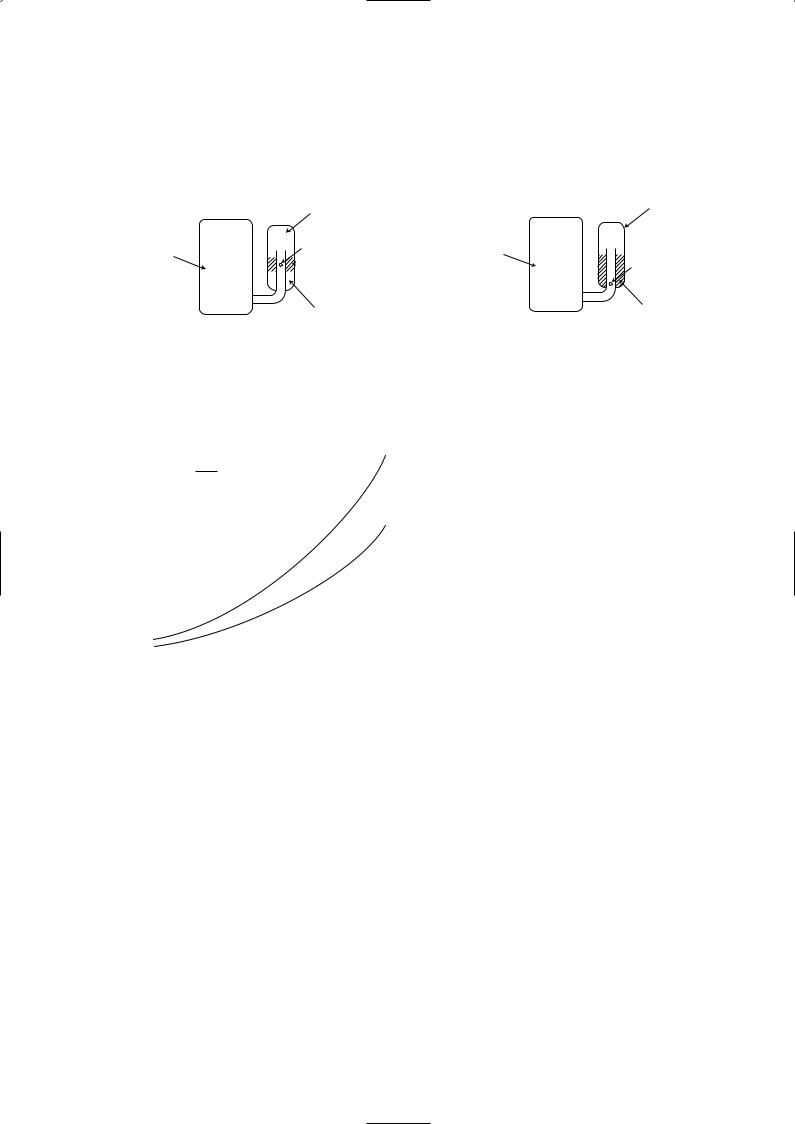
The incompatible refrigerating oil easily separates from |
Since refrigerant and refrigerating oil are compatible each, |
|
||||||||||||||
|
|
refrigerant and is in the upper layer inside the suction muffler. |
refrigerating oil backs to the compressor through the lower |
|
||||||||||||||
|
|
Raising position of the oil back hole enables to back the |
position oil back hole. |
|
||||||||||||||
|
Compressor |
refrigerating oil of the upper layer to flow back to the |
Compressor |
|
||||||||||||||
|
Compressor |
|
|
|
|
|
|
Oil back hole |
|
|||||||||
|
|
compressor. |
|
|
|
|
|
|
Suction muffler |
|
|
|
|
|
|
Suction muffler |
|
|
|
|
|
|
|
|
|
|
|
|
Refrigerating oil |
|
|
|
|
|
|
Oil back hole |
|
|
|
|
|
|
|
|
|
|
|
|
|
|
|
|
|
|
||
|
|
|
|
|
|
|
|
|
|
|
|
|
|
|
|
|
||
|
|
|
|
|
|
|
|
|
|
|
||||||||
|
|
|
|
|
|
|
|
|
Refrigerant |
|
|
|
Refrigerating oil /Refrigerant |
|
||||
|
|
|
|
|
|
|
|
|
|
|
|
|
|
|
|
|
|
|
NOTE : The unit of pressure has been changed to MPa on the international system of units(SI unit system). The conversion factor is: 1(MPa [Gauge]) =10.2(kgf/f [Gauge])
Conversion chart of refrigerant temperature and pressure
(MPa [Gauge]) |
|
|
|
|
|
|
|
|
|
|
|
|
|||
|
4.0 |
|
|
|
|
|
|
|
|
|
|
|
|
|
|
|
3.5 |
|
|
|
|
|
|
|
|
|
|
|
|
|
|
pressure |
|
|
|
|
|
R410A |
|
|
|
|
|
|
|||
|
|
|
|
|
|
|
|
|
|
|
|||||
|
|
|
|
|
|
|
|
|
|
|
|
||||
3.0 |
|
|
|
|
|
R22 |
|
|
|
|
|
|
|||
|
|
|
|
|
|
|
|
|
|
|
|
||||
liquid |
2.5 |
|
|
|
|
|
|
|
|
|
|
|
|
|
|
|
|
|
|
|
|
|
|
|
|
|
|
|
|
||
|
|
|
|
|
|
|
|
|
|
|
|
|
|
||
2.0 |
|
|
|
|
|
|
|
|
|
|
|
|
|
|
|
|
|
|
|
|
|
|
|
|
|
|
|
|
|
||
1.5 |
|
|
|
|
|
|
|
|
|
|
|
|
|
|
|
Saturated |
|
|
|
|
|
|
|
|
|
|
|
|
|
|
|
1.0 |
|
|
|
|
|
|
|
|
|
|
|
|
|
|
|
|
|
|
|
|
|
|
|
|
|
|
|
|
|
|
|
|
0.5 |
|
|
|
|
|
|
|
|
|
|
|
|
|
|
|
|
|
|
|
|
|
|
|
|
|
|
|
|
|
|
|
0.0 |
|
|
|
|
|
|
|
|
|
|
|
|
|
|
|
|
|
|
|
|
|
|
|
|
|
|
|
|
|
|
|
-0.5 |
|
|
|
|
|
|
|
|
|
|
|
|
|
|
|
-30 -20 |
-10 0 10 20 30 40 50 60 |
|||||||||||||
NOTE : The unit of pressure has been changed to MPa on the international system of units(SI unit system).
The conversion factor is: 1(MPa [Gauge]) =10.2(kgf/f [Gauge])
(:)
1.Tools dedicated for the air conditioner with R410A refrigerant
The following tools are required for R410A refrigerant. Some R22 tools can be substituted for R410A tools.
The diameter of the service port on the stop valve in outdoor unit has been changed to prevent any other refrigerant being charged into the unit. Cap size has been changed from 7/16 UNF with 20 threads to 1/2 UNF with 20 threads.
R410A tools |
Can R22 tools be used? |
Description |
|
|
|
R410A has high pressures beyond the measurement range of existing |
|
Gauge manifold |
No |
gauges. Port diameters have been changed to prevent any other refrigerant |
|
|
|
from being charged into the unit. |
|
|
|
|
|
Charge hose |
No |
Hose material and cap size have been changed to improve the pressure |
|
resistance. |
|||
|
|
||
Gas leak detector |
No |
Dedicated for HFC refrigerant. |
|
|
|
|
|
Torque wrench |
Yes |
6.35 mm and 9.52 mm |
|
No |
12.7 mm and 15.88 mm |
||
|
|||
Flare tool |
Yes |
Clamp bar hole has been enlarged to reinforce the spring strength in the tool. |
|
|
|
|
|
Flare gauge |
New |
Provided for flaring work (to be used with R22 flare tool). |
|
|
|
|
|
Vacuum pump |
New |
Provided to prevent the back flow of oil. This adapter enables you to use |
|
adapter |
vacuum pumps. |
||
|
|||
Electronic scale for |
New |
It is difficult to measure R410A with a charging cylinder because the |
|
refrigerant charging |
refrigerant bubbles due to high pressure and high-speed vaporization |
||
|
|||
|
|
|
No : Not Substitutable for R410A Yes : Substitutable for R410A 3
2.Refrigerant piping
1Specifications
Use the refrigerant pipes that meet the following specifications.
Pipe |
Outside diameter |
Wall |
Insulation material |
|
mm |
thickness |
|||
|
|
|||
|
|
|
|
|
6.35 |
0.8 mm |
|
||
For liquid |
|
|
Heat resisting foam plastic |
|
|
0.8 mm |
|||
9.52 |
||||
12.7 |
0.8 mm |
Specific gravity 0.045 Thickness 8 mm |
||
For gas |
|
|
|
|
|
|
|
||
15.881.0 mm
•Use a copper pipe or a copper-alloy seamless pipe with a thickness of 0.8 mm (6.35, 9.52, 12.7), 1.0 mm (15.88). Never use any pipe with a thickness less than 0.8 mm (6.35, 9.52, 12.7), 1.0 mm (15.88), as the pressure resistance is insufficient.
2Flaring work and flare nut
Flaring work for R410A pipe differs from that for R22 pipe.
For details of flaring work, refer to Installation manual “FLARING WORK”.
Pipe diameter |
Dimension of flare nut |
|
|
|
|
|
|
mm |
R410A |
|
R22 |
6.35 |
17 |
|
17 |
|
|
|
|
9.52 |
22 |
|
22 |
|
|
|
|
12.7 |
26 |
|
24 |
15.88 |
29 |
|
27 |
|
|
|
|
3.Refrigerant oil
Apply the special refrigeration oil (accessories: packed with indoor unit) to the flare and the union seat surfaces.
4.Air purge
•Do not discharge the refrigerant into the atmosphere.
Take care not to discharge refrigerant into the atmosphere during installation, reinstallation, or repairs to the refrigerant circuit.
•Use the vacuum pump for air purging for the purpose of environmental protection.
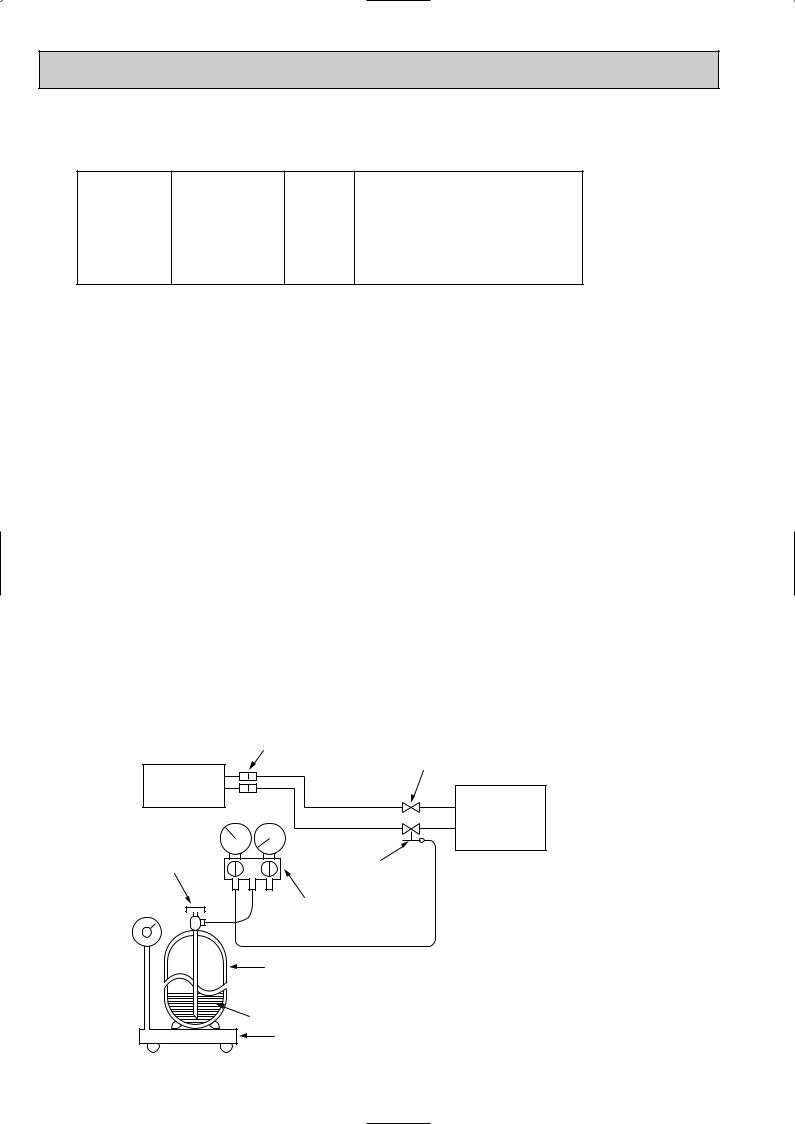
5.Additional charge
For additional charging, charge the refrigerant from liquid phase of the gas cylinder.
If the refrigerant is charged from the gas phase, composition change may occur in the refrigerant inside the cylinder and the outdoor unit. In this case, ability of the refrigerating cycle decreases or normal operation can be impossible. However, charging the liquid refrigerant all at once may cause the compressor to be locked. Thus, charge the refrigerant slowly.
Union
Stop valve
Indoor unit
Liquid pipe
Refrigerant gas cylinder operating valve
Gas pipe |
Outdoor unit |
Service port
Gauge manifold valve (for R410A)
 Charge hose (for R410A)
Refrigerant gas cylinder for R410A with siphon
Refrigerant (liquid)
Electronic scale for refrigerant charging
4
2 
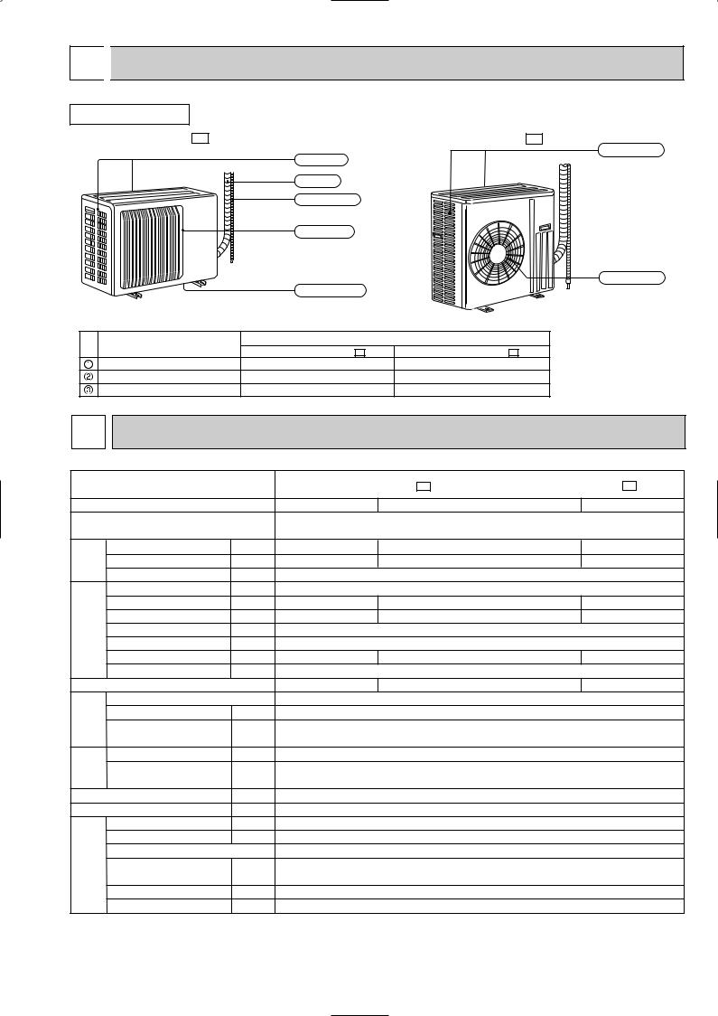
 PART NAMES AND FUNCTIONS
OUTDOOR UNIT |
|
|
|
MUCFH-A18WV - E1 |
|
MUCFH-A24WV - E1 |
|
|
Air inlet |
Air inlet |
|
|
(back and side) |
||
|
|
||
|
Piping |
|
|
|
Drain hose |
|
|
|
Air outlet |
|
|
|
|
Air outlet |
|
|
Drain outlet |
|
|
ACCESSORIES |
|
|
|
Item |
|
Q'ty |
|
MUCFH-A18WV- E1 |
MUCFH-A24WV- E1 |
||
Drain socket |
|||
1 |
1 |
||
Drain cap [33 |
2 |
6 |
|
Drain cap [16 |
1 |
– |
3 SPECIFICATION
Outdoor model
Function
Power supply
Capacity |
Air flow(High) |
K /h |
||
|
|
Capacity |
kW |
|
|
|
Dehumidification |
r/h |
|
|
|
Power outlet |
A |
|
Electrical |
data |
Running current |
A |
|
Power input |
W |
|||
|
|
|||
|
|
Power factor |
% |
|
|
|
Starting current |
A |
|
|
|
Compressor motor current |
A |
|
|
|
Fan motor current |
A |
|
Coefficient of performance(C.O.P) |
||||
Compressor |
Model |
|
||
resistance(at 20:) |
W |
|||
|
|
Output |
||
|
|
Winding |
" |
|
|
|
|
||
Fan |
motor |
Model |
" |
|
Winding |
||||
|
|
|
||
|
|
resistance(at 20:) |
|
|
|
|
Dimensions WOHOD |
mm |
|
|
|
Weight |
kg |
|
|
|
Sound level(High) |
dB |
|
|
remarks |
Fan speed(High) |
rpm |
|
Special |
Fan speed regulator |
|
||
capacity(R410A) |
|
|||
|
|
Refrigerant filling |
kg |
|
|
|
|
||
|
|
Refrigerating oil (Model) |
cc |
|
|
|
Thermistor RT61(at 0:) |
k" |
|
NOTE: Test conditions are based on ISO 5151. Cooling : Indoor DB27°C WB19°C
Outdoor DB35°C WB(24°C) Indoor-Outdoor piping length : 5m
MUCFH-A18WV - E1 |
|
MUCFH-A24WV - E1 |
||
Cooling |
Heating |
|
Cooling |
Heating |
Single phase |
|
|
Single phase |
|
230V, 50Hz |
|
|
230V, 50Hz |
|
4.8 |
5.0 |
|
6.0 |
6.8 |
2.4 |
— |
|
3.1 |
— |
2,196 |
|
|
|
2,760 |
15 |
|
|
|
25 |
8.01 |
8.38 |
|
10.51 |
11.71 |
1,730 |
1,810 |
|
2,370 |
2,640 |
94 |
|
|
|
98 |
37 |
|
|
|
74 |
7.62 |
7.99 |
|
9.93 |
11.13 |
0.39 |
|
|
|
0.58 |
2.65 |
2.65 |
|
2.45 |
2.50 |
RN196VHSHT |
|
|
NN29VBAHT |
|
1,300 |
|
|
|
1,900 |
C-R 1.80 |
|
|
|
C-R 0.80 |
C-S 3.00 |
|
|
|
C-S 1.64 |
RA6V50-OG |
|
|
RA6V85-AB |
|
WHT-BLK 116 |
|
WHT-BLK 63 BLK-YLW 30 |
||
BLK-RED 111 |
|
|
YLW-RED 63 |
|
850o605o290 |
|
840o850o330 |
||
47 |
|
|
|
74 |
52 |
|
|
|
53 |
828 |
|
|
|
730 |
1 |
|
|
|
1 |
1.85 |
|
|
|
2.20 |
520 (NEO22) |
|
1,200 (NEO22) |
||
33.18 |
|
|
|
33.18 |
Heating : Indoor |
DB20°C |
WB 15.5°C |
|
|
Outdoor DB 7°C WB 6°C
5
4 NOISE CRITERIA CURVES
MUCFH-A18WV - E1 |
|
|
|
|
MUCFH-A24WV - E1 |
|
|
|
|
||
|
|
|
|
|
|
|
|
|
|
|
|
|
FAN SPEED |
SPL(dB(A)) |
LINE |
|
|
FAN SPEED |
SPL(dB(A)) |
LINE |
|
||
|
|
|
|
|
|
|
|
|
|
|
|
|
High |
52 |
|
|
|
|
High |
53 |
|
|
|
|
|
|
|
|
|
||||||
|
|
|
|
|
|
|
|
|
|
|
|
Test conditions, |
|
|
|
|
Test conditions, |
|
|
|
|
||
|
|
Cooling : Dry-bulb temperature 35: Wet-bulb temperature (24:) |
|
|
||||||||
|
90 |
Heating : Dry-bulb temperature |
7: Wet-bulb temperature |
6: |
|
90 |
||||||
|
|
|
|
|
|
|
|
|
|
|
||
BAR |
|
|
|
|
|
|
|
|
|
|
BAR |
|
MICRO |
80 |
|
|
|
|
|
|
|
|
|
MICRO |
80 |
|
|
|
|
|
|
|
|
|
|
|
||
dB re 0.0002 |
70 |
|
|
|
|
|
|
|
|
NC-70 |
dB re 0.0002 |
70 |
|
|
|
|
|
|
|
|
|
|
|||
60 |
|
|
|
|
|
|
|
|
|
60 |
||
LEVEL, |
|
|
|
|
|
|
|
|
|
LEVEL, |
||
|
|
|
|
|
|
|
|
|
NC-60 |
|
||
50 |
|
|
|
|
|
|
|
|
|
50 |
||
PRESSURE |
|
|
|
|
|
|
|
|
|
PRESSURE |
||
|
|
|
|
|
|
|
|
|
NC-50 |
|
||
40 |
|
|
|
|
|
|
|
|
|
40 |
||
|
|
|
|
|
|
|
|
|
NC-40 |
|
||
SOUND |
|
|
|
|
|
|
|
|
|
SOUND |
|
|
30 |
|
|
|
|
|
|
|
|
|
30 |
||
|
|
|
|
|
|
|
|
|
NC-30 |
|
||
BAND |
|
|
|
|
|
|
|
|
|
BAND |
|
|
20 |
APPROXIMATE |
|
|
|
|
|
|
|
20 |
|||
OCTAVE |
THRESHOLD OF |
|
|
|
|
|
|
|
OCTAVE |
|||
|
|
|
|
|
|
|
|
|
||||
|
HEARING FOR |
|
|
|
|
|
|
NC-20 |
|
|||
|
CONTINUOUS |
|
|
|
|
|
|
|
||||
|
|
|
|
|
|
|
|
|
||||
10 |
NOISE |
|
|
|
|
|
|
|
|
10 |
||
|
|
|
|
|
|
|
|
|
||||
|
63 |
125 |
250 |
500 |
1000 |
2000 |
4000 |
8000 |
|
|||
|
|
|
|
|||||||||
Cooling : Dry-bulb temperature |
35: |
Wet-bulb temperature (24:) |
Heating : Dry-bulb temperature |
7: |
Wet-bulb temperature 6: |
|
|
|
|
|
|
|
NC-70 |
|
|
|
|
|
|
|
NC-60 |
|
|
|
|
|
|
|
NC-50 |
|
|
|
|
|
|
|
NC-40 |
|
|
|
|
|
|
|
NC-30 |
APPROXIMATE |
|
|
|
|
|
|
|
THRESHOLD OF |
|
|
|
|
|
|
|
HEARING FOR |
|
|
|
|
|
NC-20 |
|
CONTINUOUS |
|
|
|
|
|
||
|
|
|
|
|
|
||
NOISE |
|
|
|
|
|
|
|
63 |
125 |
250 |
500 |
1000 |
2000 |
4000 |
8000 |
BAND CENTER FREQUENCIES, Hz |
BAND CENTER FREQUENCIES, Hz |
OUTDOORUNIT
1m
MICROPHONE
6
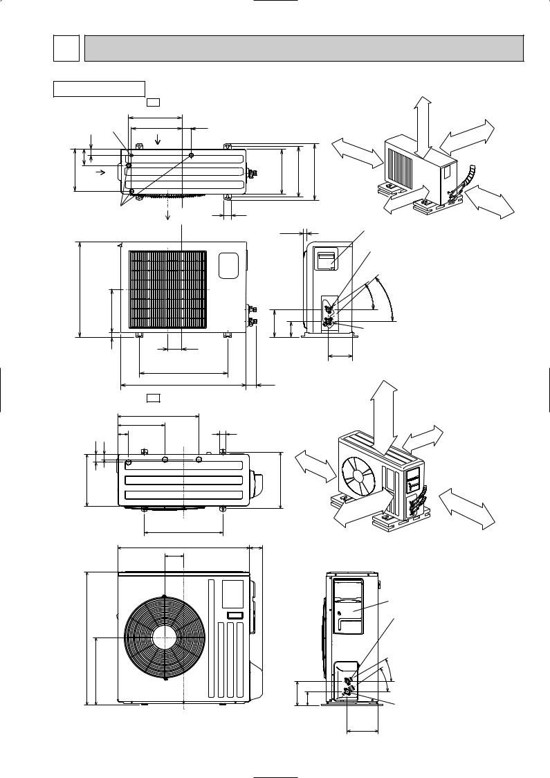
5 |
OUTLINES AND DIMENSIONS |
|
|
|||||
OUTDOOR UNIT |
|
|
|
|
|
|
|
|
MUCFH-A18WV - E1 |
|
|
|
REQUIRED SPACE |
||||
|
|
350 |
20 |
|
|
|
|
moreor |
|
Drainage |
355 |
|
|
|
|
|
|
|
|
|
|
|
|
|
|
|
|
hole [16.2 |
Air in |
|
|
|
|
100mm |
|
|
35 |
|
|
|
|
|||
|
|
|
|
|
|
|
||
|
90 |
|
|
|
|
100mm |
or |
|
|
|
|
|
|
|
|
||
248 |
|
|
290 |
310 |
345 |
more |
||
|
|
|
|
|||||
|
Air in |
|
|
|
|
|
|
|
|
|
|
|
|
|
|
|
more |
|
|
|
|
|
|
|
|
or |
|
Drainage |
|
Air out |
50 |
|
|
|
500mm |
|
|
|
|
|
|
|||
|
3holes [33 |
|
|
|
|
|
|
|
|
|
|
|
30 |
|
Service panel |
||
|
|
|
|
|
|
|||
|
|
|
|
|
|
|
|
Liquid refrigerant |
|
|
|
|
|
|
|
|
pipe joint |
|
|
|
|
|
|
|
|
Refregerant pipe |
605 |
|
|
|
|
|
|
(flared) [6.35 |
|
|
|
|
|
|
- |
- |
||
|
292 |
|
|
|
|
|
30 |
35 |
|
|
|
|
|
|
|
||
|
|
|
157 |
100 |
|
|
|
|
|
|
|
|
|
Gas refregerant |
|||
|
|
|
|
|
|
|
||
|
20 |
|
183 |
|
|
|
pipe joint |
|
|
|
|
|
161 Refregerant pipe |
||||
|
|
|
|
|
|
|||
(flared) [12.7
Unit: mm
ormore 100mm
350mm |
or |
|
more |
500 |
|
850 |
74 |
MUCFH-A24WV - E1 |
REQUIRED SPACE |
515 |
|
Open as a rule 500mm or more if the front and both sides are open
299 |
40 |
|
100mm or more |
66 |
|
||
|
200mm or more if |
||
|
|
100mm or more |
|
51 34 |
|
there are obstacles |
|
|
|
||
|
|
|
to both sides |
330 |
|
360 |
|
500 |
|
Open as a rule |
|
|
500mm or more if the back, |
350mm or more |
|
|
|
||
840 |
|
80 both sides and top are open |
|
|
|
||
121 |
|
|
|
|
|
Service panel |
|
|
Liquid refrigerant |
850 |
|
pipe joint |
|
Refrigerant pipe |
|
|
|
(flared) [6.35 |
430 |
|
- |
|
|
30 |
|
|
- |
155 |
|
35 |
90 |
Gas refrigerant |
|
|
|
|
|
|
pipe joint |
|
198 |
Refrigerant pipe |
|
|
(flared) [15.88 |
7 |
|
|
6 
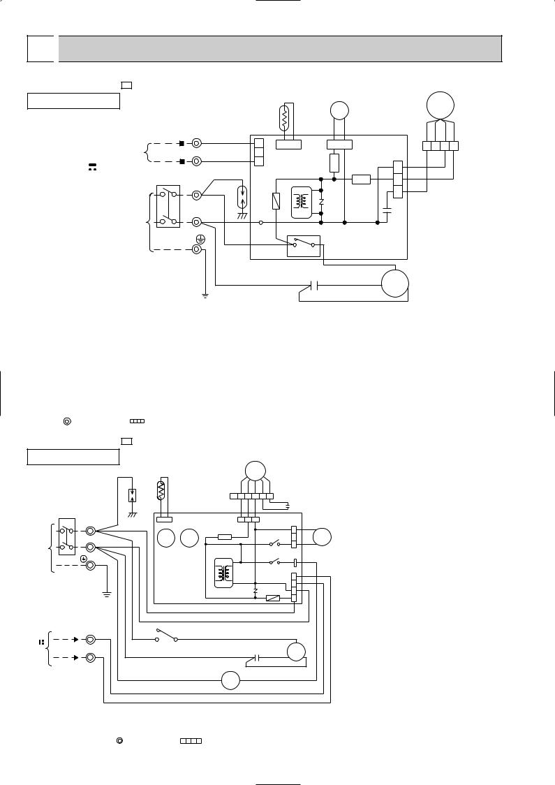
 WIRING DIAGRAM
MUCFH-A18WV - E1
MODEL WIRING DIAGRAM
OUTDOOR UNIT |
|
|
|
|
|
|
|
|
21S4 |
|
|
|
MF |
|
|
|
|
|
|
|
|
|
|
|
|
|
|
||
|
|
|
TB2 |
|
|
RT61 |
|
|
|
|
|
|
||
|
|
|
|
|
|
|
|
|
|
RED |
ORN WHT BLK |
|||
TO |
|
|
3 |
RED |
|
CN730 |
|
|
|
|
|
|||
|
|
|
1 |
CN661 |
|
CN721 |
|
|
||||||
|
|
|
|
|
|
1 2 3 4 |
||||||||
INDOOR UNIT |
|
N |
|
|
|
|
|
|||||||
|
BLK |
|
2 |
|
|
|
CN711 |
|
|
|||||
CONNECTING |
|
|
|
|
SR62 |
|
|
|||||||
|
|
|
|
3 |
|
|
|
|
WHT |
|
||||
12V |
|
|
TB1 BRN |
|
|
|
1 |
|
||||||
|
CIRCUIT BREAKER |
|
|
|
|
SR61 |
2 |
BLK |
|
|||||
|
L |
BRN |
DSAR |
|
|
|
|
RED |
|
|||||
|
|
|
|
|
F61 |
|
|
NR61 |
|
3 |
|
|||
POWER SUPPLY |
|
N BLU |
|
T61 |
|
|
C65 |
|
|
|||||
|
|
|
|
|
|
|
|
|
||||||
|
|
|
|
|
|
|
|
|
|
|||||
~ /N |
|
|
|
|
|
TAB20 |
52C |
|
|
|
|
|
||
230V |
50Hz |
PE |
|
|
|
|
|
|
|
|||||
|
|
|
|
|
|
|
|
|
|
|
||||
|
|
|
|
|
|
|
|
|
|
|
|
|
||
|
|
|
GRN/YLW |
|
|
|
|
4 |
3 |
DEICER P.C.BOARD |
|
|
||
|
|
|
|
|
|
|
|
C1 |
|
WHT |
C |
|
|
|
|
|
|
|
|
BLU |
|
|
RED |
|
|
|
|||
|
|
|
|
|
|
|
|
MC |
|
|
||||
|
|
|
|
|
|
|
|
|
R |
|
||||
|
|
|
|
|
|
|
|
|
BLK |
S |
|
|||
|
|
|
|
|
|
|
|
|
|
|
|
|
|
|
SYMBOL |
NAME |
|
SYMBOL |
NAME |
SYMBOL |
NAME |
C1 |
COMPRESSOR CAPACITOR |
MF |
OUTDOOR FAN MOTOR (INNER PROTECTOR) |
TB1,TB2 |
TERMINAL BLOCK |
|
C65 |
OUTDOOR FAN CAPACITOR |
NR61 |
VARISTOR |
21S4 |
R.V. COIL |
|
|
|
|
|
|
|
|
DSAR |
SURGE ABSORBER |
RT61 |
DEFROST THERMISTOR |
52C |
COMPRESSOR CONTACTOR |
|
|
|
|
|
|
|
|
F61 |
FUSE (2A) |
|
SR61,SR62 |
SOLID STATE RELAY |
|
|
|
|
|
|
|
|
|
MC |
COMPRESOR (INNER PROTECTOR) |
T61 |
TRANSFORMER |
|
|
|
|
|
|
|
|
|
|
NOTES: 1.About the indoor side electric wiring refer to the indoor unit electric wiring diagram for servicing. |
|
|
||||
2.Use copper conductors only. (For field wiring) |
|
|
|
|||
3.Symbols below indicate. |
|
|
|
|
|
|
|
: Terminal block |
: Connector |
|
|
|
|
MUCFH-A24WV - E1
MODEL WIRING DIAGRAM
OUTDOOR UNIT
|
|
|
|
DSAR |
RT61 |
|
YLWYLW |
|
BLKBLK |
MF |
|
|
|
|
|
|
|
|
|
BRN |
|
|
|
WHTWHT |
ORN |
RED |
|
|
|
|
|||
|
|
|
|
|
|
|
6 |
5 |
4 |
3 |
2 |
1 |
RED |
C2 |
|
|
CIRCUIT BREAKER |
|
|
|
|
|
|
|
|
ORN |
|
||||||
|
|
|
|
|
|
|
CN711CN721 |
|
||||||||
SUPPLYPOWER |
|
L |
TB1 |
|
CN661 |
|
|
1 |
2 |
3 |
|
|||||
50Hz230V/N~ |
GRN/YLW |
|
|
|
|
|
|
|
|
|
|
|
1 |
|
||
|
|
X62 |
X52 |
|
|
|
|
X62 |
|
|
21S4 |
|||||
|
|
N |
|
|
SR61 |
|
|
|
|
|
2 |
|||||
|
|
|
|
|
|
|
|
|
|
|
|
|
|
|
||
|
|
|
|
|
|
|
|
|
|
COM |
|
NO |
3 |
|
||
|
|
|
|
|
|
|
|
|
|
|
|
|
|
|||
|
|
|
PE |
|
|
|
|
|
|
|
X52 |
|
TAB52 |
|
||
|
|
|
|
|
|
|
|
|
|
|
|
|
|
|||
|
|
|
|
|
|
|
|
|
|
|
COM |
|
NO |
|
|
|
|
|
|
|
|
|
|
|
|
|
|
|
CN730 7 |
|
|||
|
|
|
|
|
DEICER |
T61 |
|
|
|
|
|
|
|
5 |
|
|
|
|
|
|
|
NR61 |
|
F61 |
3 |
|
|||||||
CONNECTING |
|
3 TB2 |
|
P.C. BOARD |
|
|
|
|
|
|
|
|
1 |
|
||
|
BRN |
3 |
4 |
WHT |
|
|
|
|
|
|
|
C |
|
|||
|
|
|
|
|
BRN |
|
|
|
|
|
|
|
|
|
|
|
|
|
|
|
BLU |
|
|
|
|
|
|
|
|
|
|
|
|
UNIT |
12V |
N |
|
BLU |
52C |
|
|
|
|
C1 |
|
|
S |
MC R |
|
|
|
|
|
|
|
|
|
|
|
||||||||
|
|
|
|
|
|
|
|
|
RED |
|
||||||
INDOOR |
|
|
|
|
|
|
|
|
|
|
|
BLK |
|
|
||
|
|
|
BLU |
|
|
A1 52C |
A2 |
|
|
|
|
|
BLU |
|
||
|
|
|
|
|
|
|
|
|
|
|
|
|||||
TO |
|
|
|
|
|
|
|
|
|
|
|
|
|
|
RED |
|
|
|
|
|
|
|
|
|
|
|
|
|
|
|
|
BLU |
|
|
|
|
|
|
|
|
|
|
|
|
|
|
|
|
|
|
SYMBOL |
NAME |
C1 |
COMPRESSOR CAPACITOR |
C2 |
OUTDOOR FAN CAPACITOR |
DSAR |
SURGE ABSORBER |
|
|
F61 |
FUSE (3.15A) |
|
|
MC |
COMPRESSOR (INNER PROTECTOR) |
|
|
MF |
OUTDOOR FAN MOTOR (INNER PROTECTOR) |
|
|
NR61 |
VARISTOR |
|
|
RT61 |
DEFROST THERMISTOR |
SR61 |
SOLID STATE RELAY |
TB1 |
TERMINAL BLOCK |
TB2 |
TERMINAL BLOCK |
T61 |
TRANSFORMER |
|
|
X52 |
CONTACTOR |
|
|
X62 |
R. V. COIL RELAY |
|
|
21S4 |
R. V. COIL |
|
|
52C |
COMPRESSOR CONTACTOR |
NOTES: 1.Use copper conductors only (For field wiring).
2.Since the indoor and outdoor unit connecting wires have polarity, connect them according to the numbers (3,N). 3.Symbols below indicate.
: Terminal block, : Connector
8
7 
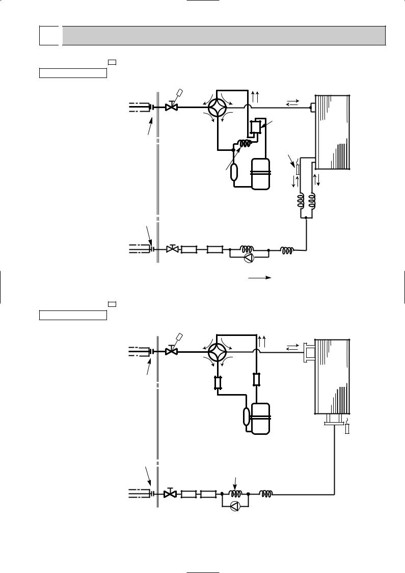
 REFRIGERANT SYSTEM DIAGRAM
MUCFH-A18WV - E1 |
|
|
Unit:mm |
OUTDOOR UNIT |
|
|
|
Refrigerant pipe [12.7 |
4- way valve |
|
|
(with heat insulator) |
|
|
|
Stop valve |
Oil separator |
|
|
(with service port) |
#100 |
Outdoor |
|
Flared connection |
|
Defrost |
heat |
|
exchanger |
||
|
thermistor |
||
|
|
|
|
|
|
RT61 |
|
|
Capillary tube |
|
|
|
[2.5o[0.6o1,000 |
|
|
|
|
Compressor |
|
Flared connection
Refrigerant pipe[6.35 (with heat insulator)
Receiver
Stop valve
Capillary tube [3.0o[1.6o650
Strainer |
|
#100 |
Check valve |
Capillary tube [3.0o[1.6o750 (2 pcs)
R.V. coil Heating ON
Cooling OFF
Capillary tube [3.0o[1.6o500
Refrigerant flow in cooling
 Refrigerant flow in heating
MUCFH-A24WV - E1
OUTDOOR UNIT
Refrigerant pipe [15.88 |
4- way valve |
|
|
|
(with heat insulator) |
|
|
|
|
|
|
|
|
|
|
Stop valve |
|
|
|
|
(with service port) |
|
Outdoor |
|
Flared connection |
|
|
Muffler |
heat |
|
Muffler |
#100 |
exchanger |
|
|
|
|||
Compressor |
Defrost |
|
thermistor |
||
|
||
|
RT61 |
Flared connection |
Capillary tube |
|
|
|
[3.0X[2.0X400 |
|
|
Receiver |
|
|
|
Stop valve |
Strainer |
Capillary tube |
R.V. coil |
Refrigerant pipe [6.35 |
#100 |
[3.0X[2.0X800 |
Heating ON |
Check valve |
|
Cooling OFF |
|
(with heat insulator)
 Refrigerant flow in cooling
 Refrigerant flow in heating
9
MAX. REFRIGERANT PIPING LENGTH & MAX. HEIGHT DIFFERENCE
Model |
Refrigerant piping |
Piping size O.D. : mm |
|
|
MAX. length :mm |
|
|
|
|
|
A |
Gas |
|
Liquid |
MUCFH-A18WV - E1 |
25 |
{12.7 |
|
{6.35 |
MUCFH-A24WV - E1 |
{15.88 |
|
||
|
|
|
||
wIt does not matter which unit is higher.
Max. Height |
difference |
10m |
W |
|
|
A: Refrigerant piping Max.length 25m
ADDITIONAL REFRIGERANT CHARGE (R410A : g)
If pipe length exceeds 7m, additional refrigerant (R410A) charge is required.
Models |
Outdoor unit: |
|
Refrigerant piping length (one way) |
|
|||
precharged |
7m |
10m |
15m |
20m |
25m |
||
|
|||||||
|
|
|
|
|
|
|
|
MUCFH-A18WV - E1 |
1,850 |
0 |
60 |
160 |
260 |
360 |
|
MUCFH-A24WV - E1 |
2,200 |
||||||
|
|
|
|
|
|||
Calculation : g=20g/m (Refrigerant piping length (m)-7)
8 
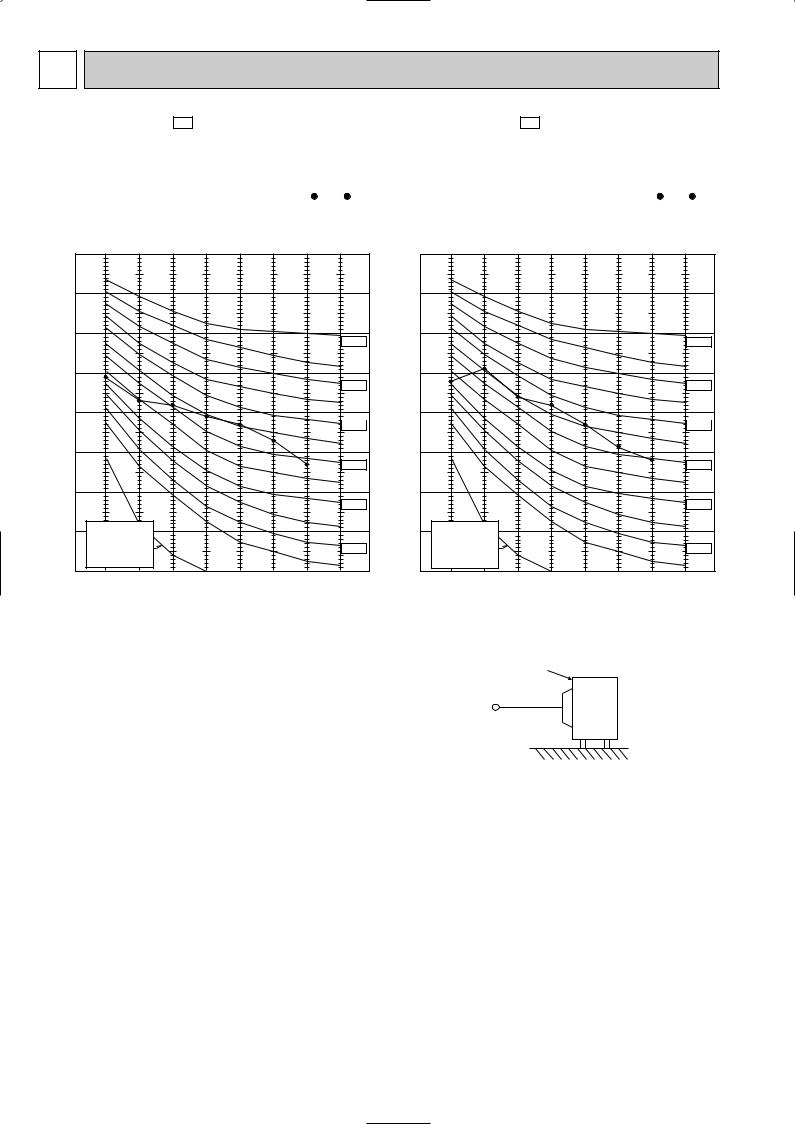
 PERFORMANCE CURVES
MUCFH-A18WV - E1 MUCFH-A24WV - E1
The standard data contained in these specifications apply only to the operation of the air conditioner under normal condition. Operating conditions vary according to the areas where these units are installed. The following information has been provided to clarify the operating characteristics of the air conditioner under the conditions indicated by the performance curve.
(1) GUARANTEED VOLTAGE
198~264V, 50Hz
(2) AIR FLOW
Air flow should be set at MAX.
(3) MAIN READINGS
COOLING |
HEATING |
||
(1) |
Indoor intake air wet-bulb temperature : ˚CWB |
(1) |
Indoor intake air dry-bulb temperature : ˚CDB |
(2) |
Indoor outlet air wet-bulb temperature : ˚CWB |
(2) |
Indoor outlet air dry-bulb temperature : ˚CDB |
(3) |
Outdoor intake air dry-bulb temperature : ˚CDB |
(3) |
Outdoor intake air wet-bulb temperature : ˚CWB |
(4) Total input : W |
(4) Total input : W |
||
Indoor air wet/dry-bulb temperature difference on the left side of the chart on next page shows the difference between the indoor intake air wet/dry-bulb temperature and the indoor outlet air wet/dry-bulb temperature for your reference at service.
10

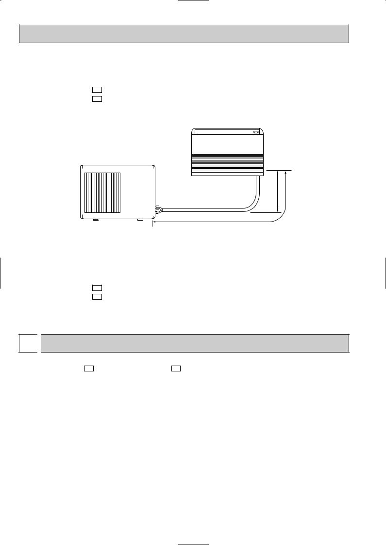
How to measure the indoor air wet-bulb/dry-bulb temperature difference
1.Attach at least 2 sets of wet and dry-bulb thermometers to the indoor air inlet as shown in the figure, and at least 2 sets of wet and dry bulb thermometers to the indoor air outlet. The thermometers must be attached to the position where air speed is high.
2.Attach at least 2 sets of wet and dry-bulb thermometers to the outdoor air inlet.
Cover the thermometers to prevent direct rays of the sun.
3.Check that the air filter is cleaned.
4.Open windows and doors of the room.
5.Press the EMERGENCY OPERATION switch once(twice) to start the EMERGENCY COOL(HEAT) MODE.
6.When system stabilizes after more than 15 minutes, measure temperature and take an average temperature.
7.10 minutes later, measure temperature again and check that the temperature does not change.
INDOOR UNIT |
OUTDOOR UNIT |
|
Air out |
Wet and dry-bulb |
|
thermometers |
||
|
Air in |
FRONT VIEW
11.1 14.7
10.2 13.4
9.2 12.1
8.3 10.9
7.5 9.7
6.6 8.5
MCFH-A18WV- E1 |
MUCFH-A18WV- E1 |
MCFH-A24WV- E1 |
MUCFH-A24WV- E1 |
23.431.8
21.629.3
19.826.9
18.0 |
24.4 |
16.222.0
14.419.5
12.617.1
10.814.7
MCFH-A18WV- E1 |
MUCFH-A18WV- E1 |
MCFH-A24WV- E1 |
MUCFH-A24WV- E1 |
|
|
Wet and dry-bulb
thermometers BACK VIEW
OUTDOOR LOW PRESSURE AND OUTDOOR UNIT CURRENT
COOL operation
1 Both indoor and outdoor units are under the same temperature/humidity condition.
Dry Bulb temperature (˚C) |
Relative humidity (%) |
20 |
50 |
25 |
60 |
30 |
70 |
11
 Loading...