


SPLIT-TYPE, AIR CONDITIONERS
No. OB397
SERVICE MANUAL
Wireless type
Models
MU-A08VD- P1
MU-A10VD- P1
MU-A13VD- P1
CONTENTS
Indication of model name
MU-A08VD - P1 MU-A10VD - P1 MU-A13VD - P1
1.TECHNICAL CHANGES ················
2.PART NAMES AND FUNCTIONS············
3.SPECIFICATION····················
4.OUTLINES AND DIMENSIONS ·············
5.WIRING DIAGRAM ··················
6.REFRIGERANT SYSTEM DIAGRAM ···········
7.PERFORMANCE CURVES ···············
8.TROUBLESHOOTING·················
9.DISASSEMBLY INSTRUCTIONS·············
10.PARTS LIST······················
11.OPTIONAL PARTS ···················
TM |
NOTE:
•This service manual describes technical data of outdoor units.
•As for indoor units MS-A08VD - P1 ,MS-A10VD - P1 and MS-A13VD - P1 , refer to the service manual OB396.
1 TECHNICAL CHANGES
MU-07UV - P1 MU-A08VD - P1
1.Outdoor unit model has been changed.
•Dimension has been changed. (780Wo540Ho255D 800Wo550Ho285D) •Valve bed has been added.
2.Compressor has been changed. (RH135VGCC RH135VHCC)
3.Outdoor fan motor has been changed. (RA6V23-HA RA6V21-AC)
4.Outdoor fan motor capacitor has been changed.
5.Compressor capacitor has been changed.
MU-10UV - P1 MU-A10VD - P1
1.Outdoor unit model has been changed.
•Dimension has been changed. (780Wo540Ho255D 800Wo550Ho285D) •Valve bed has been added.
2.Compressor has been changed. (RH165VGCC RH145VHCC)
3.Outdoor fan motor has been changed. (RA6V23-HA RA6V21-AC)
4.Outdoor fan motor capacitor has been changed.
5.Compressor capacitor has been changed.
MU-13UV - P1 MU-A13VD - P1
1.Outdoor unit model has been changed.
•Dimension has been changed. (780Wo540Ho255D 800Wo550Ho285D) •Valve bed has been added.
2.Compressor has been changed. (RH231VHAC RH207VHAC)
3.Outdoor fan motor has been changed. (RA6V33-FA RA6V33-KA)
4.Outdoor fan motor capacitor has been changed.
5.Compressor capacitor has been changed.
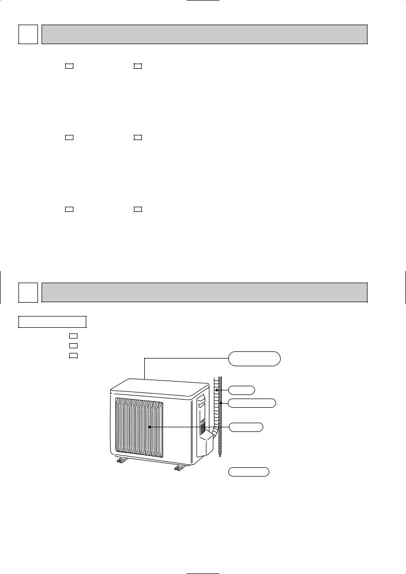
2 PART NAMES AND FUNCTIONS
OUTDOOR UNIT
MU-A08VD - P1 MU-A10VD - P1 MU-A13VD - P1
Air inlet (back )
Piping
Drain hose
Air outlet
 Drain outlet
2
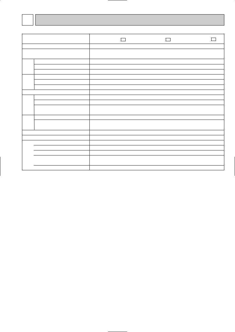
3 SPECIFICATION
Outdoor model
Function
Power supply
Capacity |
Capacity |
kW |
|
|
|||
|
Dehumidification |
R/h |
|
Electrical data |
Air flow |
K /h |
|
Starting current |
A |
||
|
|||
|
Compressor motor current |
A |
|
|
Fan motor current |
A |
|
Coefficient of performance (C.O.P) |
|||
Compressor |
Model |
|
|
Output |
W |
||
|
|||
|
Winding |
" |
|
|
resistance (at20:) |
||
|
|
||
Fan motor |
Model |
|
|
Winding |
" |
||
|
|
||
|
resistance (at20:) |
|
|
|
Dimensions WOHOD |
mm |
|
|
Weight |
kg |
|
|
Sound level |
dB |
|
Special remarks |
Fan speed |
rpm |
|
Fan speed regulator |
|
||
Refrigerant filling |
kg |
||
|
capacity (R22) |
||
|
|
||
|
Refrigeration oil (Model) |
cc |
|
MU-A08VD - P1 |
|
MU-A10VD - P1 |
MU-A13VD - P1 |
|
|
|
Cooling |
|
|
|
|
Single phase |
|
|
|
|
220-230-240V, 50Hz |
|
|
2.3-2.3-2.3 |
|
2.75-2.75-2.75 |
|
3.7-3.7-3.7 |
1.0 |
|
1.2 |
|
1.7 |
1740-1800-1860 |
|
1848-1872-1896 |
||
17-18-19 |
|
|
28-29.5-31 |
|
|
18-19-20 |
|
||
2.85-2.85-2.84 |
|
3.22-3.22-3.21 |
|
4.53-4.52-4.51 |
0.24-0.25-0.25 |
|
0.33-0.34-0.35 |
||
3.24-3.24-3.24 |
|
3.46-3.46-3.46 |
|
3.36-3.36-3.36 |
RH135VHCC |
|
RH145VHCC |
|
RH207VHAC |
650 |
|
700 |
|
1000 |
C-R 4.18 |
|
C-R 4.03 |
|
C-R 2.59 |
C-S 5.76 |
|
C-S 5.71 |
|
C-S 3.94 |
|
RA6V21-AC |
|
RA6V33-KA |
|
WHT-BLK 347 |
|
WHT-BLK 215 |
||
BLK-RED 281 |
|
BLK-RED 307 |
||
|
|
800o550o285 |
|
|
|
31 |
|
|
|
|
|
36 |
||
|
44-45-46 |
|
47-47-48 |
|
725-745-770 |
|
835-845-855 |
||
|
1 |
|
|
|
|
0.55 |
|
|
|
|
|
1.05 |
||
|
300 (MS56) |
|
520 (MS56) |
|
|
|
|
|
|
NOTE: Test conditions are based on JIS C 9612.
Cooling : Indoor |
DB27°C / WB19°C |
Outdoor |
DB35°C / WB24°C |
Indoor-Outdoor piping length 5 m
3

4 OUTLINES AND DIMENSIONS
OUTDOOR UNIT
MU-A08VD - P1
MU-A10VD - P1
MU-A13VD - P1
400 |
Drain hole [42 |
Air in |
|
344.5 |
285 |
44 |
|
Air in |
|||
|
|
2 holes 10X21 |
40 |
|
Air out
22.3
Handle
550 280 10
150
302.5
500 Bolt pitch for installation
800
Unit : mm
REQUIRED SPACE
 Basically open 100mm or more without any obstruction in front and on both sides of the unit.
Bolt forpitchinstallation304~325
17.5 23
|
|
|
|
or |
more |
|
|
|
|
|
|
|
|
|
|
100mm |
|
|
|
100mm |
|
|
|
or |
|
|
|
|
|
|
|
|
|
|
|
|
|
|
|
|
more |
|
|
|
|
|
|
|
|
or |
more |
|
350mm |
or |
more |
|
|
|
|
||||
|
|
|
|
|
|
||
|
200mm |
|
|
|
|
|
|
Open two sides of left, right, or rear side.
Service panel
Liquid refrigerant pipe joint |
|
Refrigerant pipe (flared) [6.35 |
|
- |
- |
35 |
43 |
164.5 |
|
69 |
99.5 |
170.5 |
Gas refrigerant pipe joint |
|
|
Refrigerant pipe (flared) [9.52 |
(MU-A08/A10VD) |
||
|
|
Service port |
Refrigerant pipe (flared) [12.7 |
(MU-A13VD) |
5 WIRING DIAGRAM
OUTDOOR UNIT MU-A08VD - P1 MU-A10VD - P1 MU-A13VD - P1
CONNECTING |
240V~-230- |
MODEL WIRING DIAGRAM |
|||
TB |
|
|
C |
||
|
|
|
|
WHT |
|
|
|
2 |
|
|
|
UNIT |
220 |
|
|
|
BLU C1 RED S MC |
TOINDDOR |
|
N |
|
WHT |
R |
|
|
|
BLK |
||
|
|
|
|
|
|
|
|
|
BLU |
|
C2 |
|
|
|
|
|
|
RED 3 RED
2 BLK MF WHT 1 WHT
SYMBOL |
NAME |
SYMBOL |
NAME |
SYMBOL |
NAME |
|
|
|
|
|
|
C1 |
COMPRESSOR CAPACITOR |
MC |
COMPRESSOR (INNER PROTECTOR) |
TB |
TERMINAL BLOCK |
|
|
|
|
|
|
C2 |
OUTDOOR FAN CAPACITOR |
MF |
OUTDOOR FAN MOTOR (INNER FUSE) |
|
|
NOTE:1. About the indoor side electric wiring refer to the indoor unit electric wiring diagram for servicing.
2.Use copper conductors only. (For field wiring)
3.Symbols below indicate.
/: Terminal block,  : Connector
4

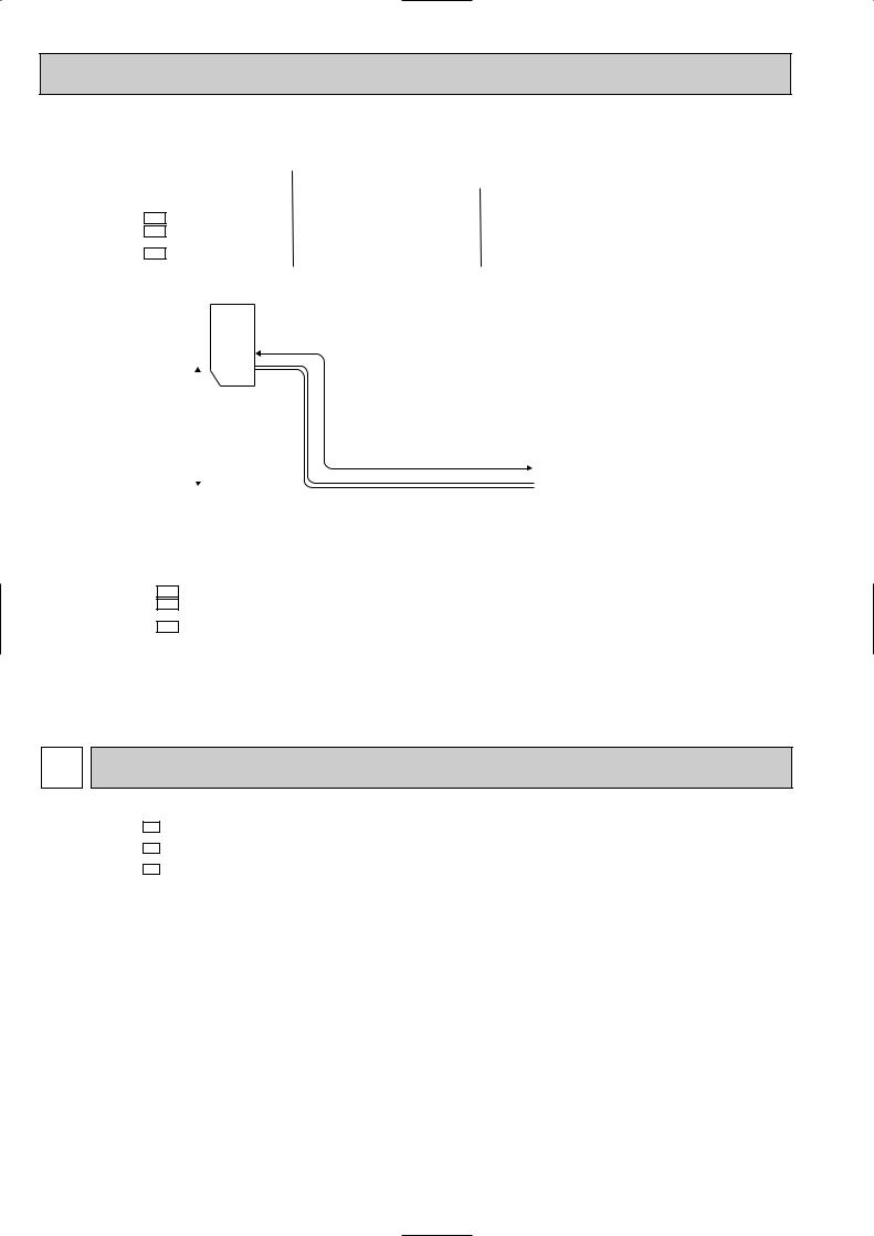
6 REFRIGERANT SYSTEM DIAGRAM
Unit : mm
MU-A08VD - P1
MU-A10VD - P1
OUTDOOR UNIT
Refrigerant pipe |
|
(Option){9.52 |
Stop valve |
(with heat insulator) |
(with service port) |
Flared |
Outdoor |
|
heat |
||
connection |
||
exchanger |
||
|
||
|
Compressor |
Strainer #100
Flared connection
Stop valve Capillary tube Refrigerant pipe {3.0 x { 1.6 x 850
(Option){6.35 (with heat insulator)
 Refrigerant flow in cooling
MU-A13VD - P1
OUTDOOR UNIT
Refrigerant pipe |
|
(Option){12.7 |
Stop valve |
(with heat insulator) |
(with service port) |
|
Outdoor heat |
Flared |
exchanger |
|
connection
Compressor 
 Strainer
#100
Flared connection
Stop valve |
Capillary tube |
|
Refrigerant pipe |
{3.0 x {1.6x650 |
|
(Option){6.35 |
Refrigerant flow in cooling |
|
(with heat insulator) |
||
|
||
|
5 |
MAX.REFRIGERANT PIPING LENGTH
|
|
|
Refrigerant piping : m |
|
|
Piping size O.D : mm |
|
|
|
|
|
|||||||
Model |
|
|
|
|
|
|
|
|
|
|
|
|
||||||
|
Max. length |
Max. height |
|
|
|
|
|
|||||||||||
|
|
|
|
|
|
|
|
|
|
|
||||||||
|
|
|
A |
|
B |
|
|
Gas |
|
|
Liquid |
|
|
|
|
|
||
MU-A08VD - P1 |
|
20 |
10 |
|
|
{9.52 |
|
|
|
|
|
|
|
|
|
|||
MU-A10VD - P1 |
|
|
|
|
{6.35 |
|
|
|
|
|
||||||||
MU-A13VD - P1 |
|
20 |
10 |
|
|
{12.7 |
|
|
|
|
|
|
||||||
|
|
|
|
|
|
|
|
|
|
|
|
|||||||
|
|
|
|
|
|
|
|
|
|
|
|
|
|
|
|
|
|
|
MAX.HEIGHT DIFFERENCE |
|
|
|
|
|
|
|
|
|
|
|
|
|
|
||||
|
|
|
Indoor |
|
|
|
|
|
|
|
|
|
|
|
|
|
|
|
|
|
|
unit |
|
|
|
|
|
|
|
|
|
|
|
|
|
|
|
|
|
|
|
|
|
|
|
|
|
|
|
|
|
|
|
|
|
|
|
|
w Max. Height |
|
|
|
|
|
|
|
|
|
|
|
|
|
|
||
|
|
|
B |
|
|
Refrigerant Piping |
|
|
|
|
|
|
|
|
|
|||
|
|
|
|
|
|
|
|
|
Max. Length |
|
|
|
|
|
|
|
|
|
|
|
|
|
|
|
|
|
|
|
|
|
|
|
|
|
|
|
|
|
|
|
|
|
|
|
|
|
A |
|
|
|
|
|
|
|
|
|
|
|
|
|
|
|
|
|
|
|
|
|
|
Outdoor unit |
|
|
|
|
|
|
|
|
|
|
|
|
|
|
|
|
|
|
|
|
|
|
|
|
ADDITIONAL REFRIGERANT CHARGE(R22 : g) |
|
|
|
|
|
|
|
|
|
|||||||||
|
|
|
|
|
|
|
|
|
||||||||||
|
|
|
|
|
|
|
|
|
|
|
|
|
|
|
||||
Model |
|
Outdoor unit precharged |
|
|
Refrigerant piping length (one way) |
|
||||||||||||
|
|
|
|
|
|
|
|
|
|
|
||||||||
|
|
7m |
|
|
10m |
|
15m |
|
20m |
|||||||||
|
|
|
|
|
|
|
|
|
|
|
|
|
||||||
|
|
|
|
|
|
|
|
|
|
|
|
|
|
|
|
|
|
|
MU-A08VD - P1 |
|
550 |
|
|
0 |
|
|
45 |
|
120 |
|
195 |
||||||
MU-A10VD - P1 |
|
|
|
|
|
|
||||||||||||
MU-A13VD - P1 |
|
1050 |
|
|
0 |
|
45 |
|
120 |
|
195 |
|||||||
|
|
|
|
|
|
|
|
|
|
|
|
|
|
|
|
|
|
|
NOTE : Calculation : Xg=15g/m (Refrigerant piping length (m)-7)
7 PERFORMANCE CURVES
MU-A08VD - P1
MU-A10VD - P1
MU-A13VD - P1
The standard data contained in these specifications apply only to the operation of the air conditioner under normal conditions. Since operating conditions vary according to the areas where these units are installed. The following information has been provided to clarify the operating characteristics of the air conditioner under the conditions indicated by the performance curve.
(1)GUARANTEED VOLTAGE
198 ~ 264V, 50Hz
(2)AIR FLOW
Air flow should be set at MAX.
(3) MAIN READINGS
(1) |
Indoor intake air wet-bulb temperature : |
°CWB |
(2) |
Indoor outlet air wet-bulb temperature : |
°CWB |
(3) |
Outdoor intake air dry-bulb temperature : |
°CDB |
(4) Total input: |
W |
|
Indoor air wet/dry-bulb temperature difference on the left side of the chart on next page shows the difference between the indoor intake air wet/dry-bulb temperature and the indoor outlet air wet/dry-bulb temperature for your reference at service.
6
 Loading...