


NOTES ON THIS MANUAL
Keep these instructions with your computer at all times. The proper set up, use and care can help extend the life of your computer. In the event that you transfer ownership of this computer, please provide these instructions to the new owner.
This manual is divided into sections to help you locate the information you require. Along with the Table of Contents at the beginning of this manual, an Index has been provided to help you find topical information.
If you want to start up your PC immediately, please read the chapters Operational Safety (page 3) and Setting up and Getting Started (page 8).
We strongly recommend you read this entire manual to ensure the proper set-up and operation of your PC.
Many application programs incorporate extensive help functions. As a general rule, you can access help functions by pressing F1 on the keyboard. These help functions will be available to you while you are using the Microsoft Windows® operating system or the respective application program.
We strongly recommend that you read the Online Manual for your PC, which can be found in the Start Menu.
Information about your PC
This interactive manual is designed to provide additional information about your PC as well as useful links accessible via the World Wide Web.
Windows invites you to a tour (note on the task bar) to familiarize yourself with the operating system. We listed further useful sources of information starting on page 59

AUDIENCE
These instructions are intended for both the novice and advanced user. Regardless of the possible professional utilisation, this PC is designed for day-to-day household use. The functions and applications for use with this PC have been designed with the entire family in mind.
PURCHASE DETAILS
Enter your purchase details below for quick reference.
Serial Numbers ......................................
(i.e. Microsoft®) ......................................
Place and date of Purchase ......................................
You will find the PC serial number on the Service Hotline card. The serial number also appears on the rear of the PC.
QUALITY
Medion has selected the components in this computer for their high level of functionality, ease of use, safety and reliability.
Through balanced hardware and software design we are able to provide you with an innovative personal computer useful for applications relating to both work and leisure.
We are pleased to welcome you as our newest customer. Thank you for choosing our products.
© 2006 Medion®. All rights reserved. Microsoft®, MS-DOS®, and Windows are registered trademarks of Microsoft Corporation in the U.S. and other countries. Pentium® is a registered trademark of Intel Corporation. The names of actual companies and products mentioned herein may be the trademarks of their respective owners.
Information in this document is subject to change without notice.
ii

Table of contents |
|
Safety.......................................................................... |
1 |
Operational safety....................................................... |
3 |
Data security ........................................................... |
4 |
Setting up & Getting started....................................... |
5 |
Included with your PC.................................................. |
7 |
Setting up.................................................................. |
8 |
Set-up location......................................................... |
8 |
Ambient temperature ................................................ |
8 |
Ergonomics.............................................................. |
9 |
Connecting .............................................................. |
12 |
Cabling ................................................................. |
12 |
Front connectors .................................................... |
13 |
Connecting the monitor ........................................... |
14 |
Installing wireless keyboard & mouse ........................ |
15 |
Inserting batteries in mouse .................................. |
15 |
Inserting batteries in keyboard............................... |
16 |
Setting the frequency channel or ID........................ |
17 |
Connecting the receiver ........................................ |
18 |
Connecting a USB keyboard/mouse........................... |
19 |
Connecting a PS/2 keyboard/mouse .......................... |
19 |
Connecting parallel devices ...................................... |
19 |
USB/IEEE 1394 ...................................................... |
20 |
Connecting USB devices ........................................ |
20 |
Connecting IEEE 1394 (Fire Wire) devices................ |
20 |
Connecting speakers/audio output ............................ |
21 |
PCs with Surround sound ...................................... |
21 |
Connecting a microphone ........................................ |
22 |
Connecting a sound source/audio input...................... |
22 |
Connecting a recording source / video inlet ................ |
22 |
LAN connection ...................................................... |
23 |
Connecting serial devices......................................... |
23 |
Connecting the PC to a television (TV-out) ................. |
24 |
Antenna connection for TV / radio receiver ................. |
24 |
Modem connection.................................................. |
24 |
Connecting the power supply.................................... |
25 |
iii

Getting started ......................................................... |
26 |
Step 1: Power on.................................................... |
26 |
Switch ................................................................ |
26 |
On/off switch....................................................... |
26 |
Step 2: Starting initial setup .................................... |
27 |
Step 3: Finalizing ................................................... |
28 |
Short description of the Windows® desktop ............. |
28 |
Operation .................................................................. |
31 |
Multimedia at the press of a button ............................. |
33 |
Switch Power Cinema on ......................................... |
33 |
Switch Power Cinema off ......................................... |
33 |
The Mouse ............................................................... |
34 |
Power-saving function ............................................. |
34 |
The Keyboard........................................................... |
35 |
The Alt and Ctrl keys............................................... |
35 |
Multimedia functions ............................................... |
36 |
The hard drive.......................................................... |
38 |
Important directories .............................................. |
39 |
Connecting an external hard drive............................. |
39 |
The optical drive ....................................................... |
40 |
Loading a disc:....................................................... |
40 |
Playing back and retrieving data from discs ................ |
41 |
How to remove a disc: ............................................ |
41 |
The optical drive as boot drive.................................. |
41 |
Regional playback information for DVD ...................... |
42 |
Subjects concerning the CD/DVD-Rewriter ................. |
43 |
LightScribe.......................................................... |
43 |
The card reader ........................................................ |
44 |
The graphics card ..................................................... |
45 |
Performance characteristics ..................................... |
45 |
Current image playback frequencies .......................... |
45 |
Connecting the PC to a television .............................. |
46 |
How to connect the PC to a television: .................... |
47 |
The sound card......................................................... |
48 |
USB port ................................................................. |
48 |
IEEE 1394 (Fire Wire)................................................ |
49 |
Application options for IEEE1394 .............................. |
49 |
Technical specifications ........................................... |
49 |
The radio/TV tuner card ............................................. |
50 |
iv

The remote control.................................................... |
50 |
Inserting batteries .................................................. |
50 |
Button layout ......................................................... |
51 |
Changing the transmission/reception channels............ |
54 |
The network............................................................. |
55 |
What is a network? ................................................. |
55 |
Wireless LAN.......................................................... |
56 |
Safety notes ........................................................ |
56 |
Conditions........................................................... |
56 |
Troubleshooting within the network........................... |
57 |
Modem / ISDN.......................................................... |
58 |
Serial COM port ........................................................ |
58 |
Software.................................................................. |
59 |
Getting to know Windows XP.................................... |
59 |
Windows XP home edition – first steps..................... |
59 |
WindowsXP help and support................................... |
59 |
Microsoft interactive training – step by step ............. |
60 |
Writing CDs/DVDs .................................................. |
61 |
Starting nero - Express ......................................... |
61 |
Installation of software............................................ |
62 |
This is how to install your software: ........................ |
63 |
Software uninstallation.......................................... |
64 |
Windows activation ................................................. |
65 |
Product activation on your PC ................................ |
65 |
BIOS setup ............................................................ |
66 |
Execution of the BIOS setup .................................. |
66 |
Customer service & self help .................................... |
67 |
Data and system security........................................... |
69 |
Data security ......................................................... |
69 |
Maintenance programs ............................................ |
69 |
Password reset file.................................................. |
69 |
System recovery....................................................... |
70 |
Correction ............................................................. |
70 |
Windows® Update................................................... |
71 |
Windows Update information for data security .......... |
72 |
Restoring the factory settings................................... |
73 |
Limits of the recovery ........................................... |
73 |
Carrying out a restore........................................... |
74 |
FAQ – Frequently Asked Questions .............................. |
75 |
v

Customer service ...................................................... |
77 |
Troubleshooting ..................................................... |
77 |
Localise the cause .................................................. |
77 |
Errors and possible causes ....................................... |
78 |
Additional support .................................................. |
79 |
Driver support........................................................ |
79 |
Transporting the PC ................................................ |
80 |
Cleaning and care................................................... |
80 |
Recycling and disposal............................................. |
81 |
Battery treatment................................................... |
81 |
Upgrades and repairs .............................................. |
83 |
Notes for service engineers.................................... |
83 |
Appendix................................................................... |
85 |
PowerCinema Linux license agreement........................ |
87 |
License disclaimer................................................... |
87 |
Download source code .......................................... |
87 |
Standards................................................................ |
88 |
Electromagnetic compatibility ................................... |
88 |
Electrical safety...................................................... |
88 |
Ergonomics............................................................ |
89 |
Noise emission ....................................................... |
89 |
Information about the regulatory compliance of |
|
the modem............................................................ |
90 |
Information about the regulatory compliance of |
|
wireless keyboard / mouse, and wireless LAN ............. |
90 |
FCC compliance statement....................................... |
91 |
Warranty ................................................................. |
92 |
Liability limitations.................................................. |
93 |
Making copies of this manual.................................... |
93 |
Index ...................................................................... |
94 |
Device 
At the end of its life, the appliance must not be disposed of in household rubbish. Enquire about the options for environmentally-friendly disposal
Batteries 
Do not dispose of used batteries in the household rubbish! They must be deposited at a collection point for used batteries.
vi

|
Chapter 1 |
|
Safety |
Subject |
Page |
Operational safety |
..................................3 |
Data security .......................................... |
4 |
Operation Connecting Safety
Help
Appendix

2 |
|
OPERATIONAL SAFETY |
|
|
|

Operational safety
Please read this chapter carefully and observe all listed notes. This ensures reliable operation and long life expectancy of your PC.
!Do not allow children to play unattended with electrical equipment. Children are incapable of judging potential risks properly.
!Do not open the PC casing or use the PC with the casing removed. When the casing is open there is a danger to life from electric shock.
!Optical drives are Laser Class 1 devices. These lasers must remain in their sealed PC casing. Do not remove the drive covers, as exposure to the lasers may prove harmful.
!Do not insert objects through the slots and openings of the PC. This may lead to electric shock or an electrical short-circuit or fire that will damage your PC.
!Do not cover the slots and openings in the PC casing. These openings are for ventilation purposes. Covering these vents may lead to overheating.
Switch off your PC immediately or do not switch it on at all and contact customer service …
•… if the power cord or the connectors attached to it are burnt or damaged. Replace the defective power cord with an original power cord. Under no circumstances may a defective power cord be repaired.
•... if the housing of the PC is damaged or fluids have leaked into it. Have the PC checked by customer service first, because the PC may not be safely operated otherwise and there may be a life-threatening risk of electrocution!
Operation Connecting Safety
Help
Appendix
SAFETY |
|
3 |
|
|
|

DATA SECURITY
!Attention! Every time you update your data make back-up copies on an external storage medium. The supplier does not assume liability for data loss or damage to data storage units, and no claims can be accepted for damages resulting from the loss of data or consequential losses.
4 |
|
OPERATIONAL SAFETY |
|
|
|
|
Chapter 2 |
|
Setting up & |
|
Getting started |
Subject |
Page |
Included with your PC |
...............................7 |
Setting up ............................................... |
8 |
Connecting ............................................ |
12 |
Getting started ...................................... |
26 |
Operation Connecting Safety
Help
Appendix

6 |
|
OPERATIONAL SAFETY |
|
|
|

Included with your PC
Please check that the contents listed below are supplied with your package and notify us within 14 days of purchase if this is not the case. You MUST provide your PC’s serial number when contacting a customer service representative.
Your PC bundle should include the following components:
•PC and power cord
•Windows-compatible keyboard & mouse
•Headset
•Remote control
•Microsoft Windows® Getting Started manual + recovery CD
•Application-/ Support Disc
•Documentation
SETTING UP & |
7 |
GETTING STARTED
Operation Connecting Safety
Help
Appendix

Setting up
Remember that choosing the proper location for your PC is just as important as connecting it correctly. Place your PC in a stable, vibration-free area. Detailed below are additional guidelines on setting up your PC.
SET-UP LOCATION
•Keep your PC and all units connected to it away from moisture, dust, heat and direct sunlight. Failure to observe these instructions can lead to malfunctions or damage to the PC.
•To prevent damage to your PC from a fall, place and operate the PC and all connected units on a stable, balanced and vibration-free surface.
•Your PC is not suitable for use at video workstation devices in the sense of §2 of the video workstation regulation.
AMBIENT TEMPERATURE
•The PC can be operated at an ambient temperature of between 10° and 35°C (+41° and +95°F) and at a relative humidity of between 30% and 70% (without condensation).
•When powered off, the PC can be stored at temperatures between -20° and 50°C (–40° and +158°F).
•Unplug the cable during thunderstorms and make especially sure to remove the antenna cables, if present. We recommend the use of a surge protector for additional safety, in order to protect your PC from being damaged by power peaks or lightning strikes through the power network.
•Delay operating a PC after transport until the device has adjusted to the ambient temperature. In situations of large temperature or humidity differences condensation may build up moisture inside the PC, which might cause an electrical short circuit.
8 |
|
SETTING UP |
|
|
|

ERGONOMICS
iNote: Ensure that the monitor is set up in such a way that reflections, glare and light/darkness contrast are avoided.
You should not position the monitor in close proximity to a window, because this is the brightest area of the room because of daylight. This brightness impedes the adjustment of the eyes to the darker monitor.
Always position the monitor in a line of sight that runs parallel to the window front (see picture).
You should also apply a parallel line of sight with respect to artificial lighting. This means that in a room lit by artificial light essentially the same criteria and objectives apply. Should it not be possible to arrange the monitor as outlined above, the following measures might be helpful:
•Turn, lower or incline the monitor.
•Place horizontal or vertical shades at the windows.
•Working in Comfort
iNote: Take regular breaks from the work at your screen to prevent tenseness and exhaustion.
Operation Connecting Safety
Help
Appendix
SETTING UP & |
9 |
GETTING STARTED

Sitting in one position for long periods can be uncomfortable. To minimize the potential for physical discomfort or injury, it’s important that you maintain proper posture.
Overall: Change your position frequently and take regular breaks to avoid fatigue.
Back: While sitting at your work surface, make sure your back is supported by the chair’s backrest in erect position or angled slightly backwards.
Legs: Your thighs should be horizontal or angled slightly downward. Your lower legs should be near a right angle to your thighs. Your feet should rest flat on the floor. If necessary, use a footrest, but double check that you have your seat height adjusted correctly before getting a footrest.
Arms: Your arms should be relaxed and loose, elbows close to your sides, with forearms and hands approximately parallel to the floor.
Wrists: Your wrists should be as straight as possible while using the keyboard, mouse or trackball. They should not be bent sideways, or more than 10 degrees up or down.
Head: Your head should be upright or tilted slightly forward. Avoid working with your head or trunk twisted.
10 |
|
SETTING UP |
|
|
|
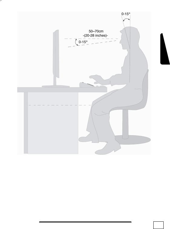
•Hand rest: 2” – 4”
•Top line of screen at eye level or slightly below
•Viewing distance: 20” – 27.5”
•Legroom (vertical): minimum 25.5”
•Legroom (horizontal): minimum 23.6”
SETTING UP &
GETTING STARTED
Operation Connecting Safety
Help
Appendix
11

Connecting
For a better guidance, open up the left inner page of the cover with the diagrams to find the location of the described connections.
!Note: The devices listed are not necessarily included with your PC.
All the connections listed are optional and will not inevitably be available on your PC.
CABLING
Please follow the instructions below in order to correctly connect your PC:
•Arrange cables in such a way that no one can tread on or trip over them.
•Do not place objects on the cables.
•To avoid damage to your PC, connect your peripherals (e.g., keyboard, mouse and monitor) whilst your PC is powered off. Some devices can be connected whilst your PC is in use. These devices usually have a USB or IEEE 1394 connector.
Please follow the appropriate instructions for each device.
•Keep the PC at least one meter (approximately three feet) away from high frequency and magnetic interference sources (e.g., televisions, loudspeaker cabinets, mobile telephones, etc.) in order to avoid malfunctions and/or loss of data.
•Please note that only shielded cables shorter than
3 metres (9.84 ft) should be used for the LPT, COM, USB, IEEE 1394, audio, video and network interfaces with this PC.
•To avoid EMC issues, make sure that all devices are connected to each cable or that cables not in use are removed from the computer.
12 |
|
CONNECTING |
|
|
|
• |
The connection of devices is limited to equipment that com- |
Safety |
||
|
||||
|
plies with EN60950 “Safety of information technology equip- |
|
||
|
ment” or EN60065 “Audio, video and similar electronic appa- |
|
||
|
ratus. Safety requirements”. |
|
||
• |
In the first hours of operation, new devices may emit a typi- |
Connecting |
||
|
opment of this product, we have made sure that the appli- |
|||
|
cal, unavoidable but completely harmless smell, which will |
|
||
|
decline increasingly in the course of time. |
|
||
|
We recommend you to ventilate the room regularly, in order |
|
||
|
to counteract the formation of the smell. During the devel- |
|
||
|
cable limits are clearly fallen below. |
|
||
i |
|
|
|
Operation |
|
Note: You only need to connect those components to |
|||
|
|
|||
|
|
your computer you require. If you do not have the |
|
|
|
|
described device (e. g. printer) you may skip the re- |
|
|
|
|
spective item and carry it out later, if necessary. |
|
|
|
|
|
|
|
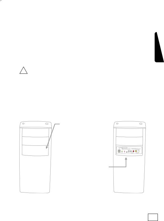
FRONT CONNECTORS
Here is how you can access the card reader and some further connectors on the front of your PC casing.
|
Press on the front |
|
|
DVD-RW |
screen, so that it |
DVD-RW |
|
folds open. The right |
|||
|
|
||
DVD-ROM |
image shows the |
DVD-ROM |
|
|
opened screen. |
|
|
Front screen |
|
|
|
|
|
||
|
|
|
|
|
Turn the screen |
|
|
|
back to its starting |
|
|
|
position. |
|
|
|
|
|
Help
Appendix
SETTING UP & |
13 |
GETTING STARTED

CONNECTING THE MONITOR
Diagram reference: W1, W2
If your graphics card has two VGA sockets, you can use either port to connect to the monitor. Your PC may optionally be equipped with a digital connector (DVI, W2). With the help of an adapter you can also use this connector for your VGA monitor.
Because of its asymmetric form the plug only fits into the socket in one position.
1.Connect the data cable of the monitor to the socket on the graphics card (reference W1 or W2). If necessary, remove the white guard-ring on the monitor plug and ensure that the plug and socket mate together precisely.
2.Hand-tighten the screws on the monitor cable.
CAUTION! Your PC monitor is preconfigured for a screen resolution of 1024 x 768 pixels and an optimal refresh rate of 75 hz. If your monitor does not support these settings it may become damaged or malfunction during use.
You can change the screen resolution and configuration of your monitor as follows (See also your monitor's User Manual):
1.Once you have powered on the PC, press the F8 key to select Safe Mode.
If you don’t hit the F8 key on time, you won‘t see the start menu which gives you the option to run in Safe Mode. Reboot your PC and retry if you have missed this.
2.Select Display Properties to designate the screen resolution for your monitor.
3.You can then adjust the “Display Features” to your monitor.
14 |
|
CONNECTING |
|
|
|
INSTALLING WIRELESS KEYBOARD & MOUSE
These devices are optional. The wireless keyboard and mouse operate with digital radio technology to ensure no hinder communication between the keyboard, the mouse and your computer without connecting cable. The transmission and receiving of keyboard and mouse are free from angle restriction. Before working with your new keyboard and mouse, take a few one-time preparations.
!Beware: Please read and follow the security advices concerning the use of batteries on page 81.
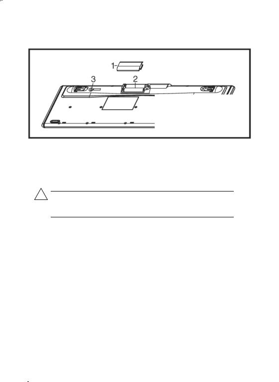
INSERTING BATTERIES IN MOUSE
The mouse requires 2 rechargeable NiMH batteries (Type: AAA).
iNote: Please use only rechargeable batteries. The use of customary batteries can lead to malfunctions or damage to the mouse.
1 = cover
2 = battery compartment
3 = channel setting button
(Diagram the same)
Remove the battery compartment cover (1) on the bottom of the mouse.
1.Insert the two rechargeable NiMH batteries (AAA) in the battery compartment.
2.Replace the battery compartment cover (1) on the bottom of mouse
3.The mouse is charged by your PC using the supplied USBcable. Connect the cable end with the small connector on the front side of the mouse and the other cable end with your PC, while the PC is switched on. Charging is completed after about 8 hours. You can continue using the mouse while it is charging.
SETTING UP &
GETTING STARTED
Operation Connecting Safety
Help
Appendix
15
INSERTING BATTERIES IN KEYBOARD
The keyboard requires two alkaline batteries (AA).
1= Cover
2= Battery compartment 3= Channel setting button
(Diagram the same)
1.Remove the battery compartment cover (1) on the bottom of the keyboard by pushing it in the direction of the arrow.
2.Insert two AA batteries. The illustration on the cover shows how to insert the batteries properly.
3.Recover the battery compartment.
iNote: Please do not push the channel setting button
(3) to the side of the battery compartment cover. It may cause the channel or ID to change.
16 |
|
CONNECTING |
|
|
|

SETTING THE FREQUENCY CHANNEL OR ID
i Important: Do not carry out the following installation steps until you have put the PC into operation as described on the following pages.
For a good wireless radio connection, you must ensure the frequency channel and/or ID of the keyboard and mouse is the same as that of the receiver.
There are 255 IDs each for keyboard and mouse. Changing the frequency channel / ID may prevent interference between devices.
Setting the frequency channel of the keyboard and mouse
1.Push the ‘connect’ button located on top of the receiver. The indicator will start blinking.
2.Push the button on the bottom of the keyboard and/or the mouse. The channel will be changed after the button is released.
iNote: Please do not hold the button for more than 3 seconds. This will change the ID, instead of the channel.
Setting the ID on the keyboard and mouse
1.Push the ‘connect’ button on top of the receiver. The indicator light on the receiver will start blinking.
2.Hold down the button on the bottom of the keyboard and/or the mouse for 3 seconds. The ID will change after the button has been released.
SETTING UP &
GETTING STARTED
Operation Connecting Safety
Help
Appendix
17

CONNECTING THE RECEIVER
Diagram reference: E
1 |
|
2 |
3
4
1 = USB receiver plug (black)
2 = Receiver
3 = Mouse
4 = Keyboard
1.Attach the USB receiver for the mouse and the keyboard to any free USB connection. It is recommended to use a connection at the back of the PC because of the visual appearance.
2.The distance between the reception station and the transmitter (keyboard and mouse) should not exceed 20 cm, in order to receive optimum wireless conditions.
iNote: Change the batteries if it is no longer possible to make entries smoothly.
The operation of the mouse and the keyboard is described on page 34.
18 |
|
CONNECTING |
|
|
|

CONNECTING A USB KEYBOARD/MOUSE
Diagram reference: E
1. Connect the USB keyboard or mouse to a free USB port.
CONNECTING A PS/2 KEYBOARD/MOUSE
Diagram reference: R / O
If you intend to connect a USB keyboard or mouse, you can skip this step.
1.Connect the PS/2 keyboard to the blue PS/2 port and the mouse to the green PS/2 port.
CONNECTING PARALLEL DEVICES
Diagram reference: P
iTake care that the connector and the socket fit exactly to avoid damaging the contacts. Because of its asymmetric form the plug only fits into the socket in one position.
Use a doubly screened, parallel connection cable (25-pin) to connect a printer:
1.Connect the printer cable from your printer to the red printer socket P on the rear of your PC.
2.Hand-tighten the screws of the printer cable.
If you wish to use a scanner, which also connects to the PC via the parallel interface, follow the instructions above. With the PC parallel port in use, the printer can be connected directly to the scanner. You will have use of both devices if they are connected in this manner.
SETTING UP &
GETTING STARTED
Operation Connecting Safety
Help
Appendix
19

USB/IEEE 1394
!Warning: Connect your USB-/IEEE 1394 devices after initial set-up of your new PC. This will prevent unnecessary confusion during installation. These devices can generally be connected during operation. Read the manual for your peripheral device first.
The voltage outputs of your PC for IEEE 1394 as well as for USB are protected by a fuse (limited power source according to EN60950). This ensures that a malfunction of the PC will not damage the peripheral devices connected to the respective jacks.
CONNECTING USB DEVICES
Diagram reference: E
You have a choice of several connection sockets.
It does not matter which you use.
1.If you wish to use a printer, scanner or other device with a USB port, connect the cable to the USB socket on your PC.
iNote: Connect your devices always to the same port otherwise your operating system will give a new ID and asks for driver installation.
CONNECTING IEEE 1394 (FIRE WIRE) DEVICES
Diagram reference: F1, F2
iNote: Peripheral devices can have different connecting cables (6-pole = F1, 4-pole = F2). Please check what kind of cable you need for your peripheral device.
!Important: The connectors of the front side are not configured for parallel use.
20 |
|
CONNECTING |
|
|
|

CONNECTING SPEAKERS/AUDIO OUTPUT
Diagram reference: H1
Here you can connect your headphones, active speakers or audio connection cables for recording. Please refer to the user's guide of your stereo installation for information about which connector you should use (usually Line In or Aux).
1.Connect your headphones or active speakers by plugging the cable with the 3.5 mm stereo jack plug into the green socket (reference H1).
Connecting Safety
PCS WITH SURROUND SOUND
Diagram reference: H1, H2, H3, H4, U1, U2
iNote: You will find information about placing speakers by starting the sound software in the task bar.
Connect your surround equipment as follows:
1.Connect the Front speaker to the green socket (reference
H1).
2.Connect your rear speaker to the Surround 1 connector (H2).
3.Your centre speaker or subwoofer can be connected to the socket Centre/Subwoofer (H3).
4.Connect to the optional Surround 2 socket (H4) two more speakers for the back surround.
A digital audio output (SPDIF) can be connected with an optical and/or coaxial cable.
1.Push the cinch cable into the socket at Position U1. Push the optical cable into the output at Position U2.
2.Connect the other end of the cable to an audio device that has a corresponding digital input.
SETTING UP &
GETTING STARTED
Operation
Help
Appendix
21

CONNECTING A MICROPHONE
Diagram reference: I
1.You can use the pink socket I to connect a microphone with a 3.5 mm mono jack plug.
2.Position the microphone in such a way that it does not point directly at the speakers. If you hear feedback, characterised by loud whistling noises, reposition the microphone until the sound stops.
CONNECTING A SOUND SOURCE/AUDIO INPUT
Diagram reference: J1, J2, T1, T2
This port is used to accommodate a connecting cable for external audio sources (i.e. stereo system, keyboard/synthesizer).
1.Connect the cable with the 3.5 mm stereo jack plug to the light-blue coloured socket (reference J1). You can also connect a stereo Cinch cable (position J2).
If you want to record a digital audio source use the (optional) audio input T1 or T2. A SPDIF-Cinch cable will also be necessary for the T1 while T2 is an optical output.
CONNECTING A RECORDING SOURCE / VIDEO INLET
Diagram reference: K, L
Depending on the configuration you can connect an external video source to your PC using an S-Video or composite (cinch) cable. These connections enable you to record and, if necessary, edit video data.
1.Connect the plug of the cord to the jack (position K for cinch and L for S-Video).
iAttention: These two front connectors cannot be used simultaneously.
22 |
|
CONNECTING |
|
|
|

LAN CONNECTION
Diagram reference: Q
Your PC is equipped with a network connection, in order to prepare it for network operation.
The network cable usually has tow RJ45 plugs so that it is unimportant which plug is connected to which jack.
1.Connect one plug of the cable to the PC jack.
2.Connect the other plug to the other PC or hub/switch.
For further information refer to chapter “The Network” starting at page 55.
CONNECTING SERIAL DEVICES
Diagram reference: S
You can connect an external modem or another serial device using this port.
iTake care that the connector and the socket fit exactly to avoid damaging the contacts. Because of its asymmetric form the plug only fits into the socket in one position.
Operation Connecting Safety
Help
1.In order to connect an external modem, card reader or other serial device, connect the serial cable with the turquoisecoloured connection socket (S) on the rear of your PC.
2.Hand-tighten the screws of the serial cable.
SETTING UP &
GETTING STARTED
Appendix
23

CONNECTING THE PC TO A TELEVISION (TV-OUT)
Diagram reference: V1, V2, V3, V4
If your computer’s VGA card is equipped with a TV-Out socket you can establish a connection to a TV. Depending on the configuration you can use a composite cable (cinch, V1), an S-Video cable (V2) a SCART cable (V3) or a component cable (V4).
iNote: These sockets are only for output purpose.
1.Connect your PC and your television with the cord required for your TV.
ANTENNA CONNECTION FOR TV / RADIO RECEIVER
Diagram reference: Y, Y2
Should your PC be equipped with a TV tuner card, then you must connect the corresponding 75 Ohm coaxial cables (aerial or cable) for radio and TV reception.
1.Connect the supplied radio antenna with the corresponding connector (Y) on the TV card.
2.Connect the TV connector on your TV card (Y2) with the aerial antenna or cable TV.
MODEM CONNECTION
Diagram reference: Z
Your PC may is fitted with an analogue modem card to prepare your PC for Internet excess and fax operation, according to the equipment. The modem cable has an RJ11 plug, which is plugged into the modem of your PC, and a TAE plug, which fits an N- coded, analogue telephone socket.
!Attention! Please observe that the modem may only be connected to an analogue telephone line. The connection of a digital system (ISDN etc.) to an analogue telephone line can possibly cause damage to the modem or the connected devices and the telecommunication network.
24 |
|
CONNECTING |
|
|
|
 Loading...