


NOTES ON THIS MANUAL
Keep these instructions with your computer at all times. The proper set up, use and care can help extend the life of your computer. In the event that you transfer ownership of this computer, please provide these instructions to the new owner.
This manual is divided into sections to help you locate the information you require. Along with the Table of Contents at the beginning of this manual, an Index has been provided to help you find topical information.
If you want to start up your PC immediately, please read the chapters Operational Safety (page 3) and Setting up and Getting Started (page 10).
We strongly recommend you read this entire manual to ensure the proper set-up and operation of your PC.
Many application programs incorporate extensive help functions. As a general rule, you can access help functions by pressing F1 on the keyboard. These help functions will be available to you while you are using the Microsoft Windows® operating system or the respective application program.
We strongly recommend that you read the Online Manual for your PC, which can be found in the Start Menu.
Information about your PC
This interactive manual is designed to provide additional information about your PC as well as useful links accessible via the World Wide Web.
Windowsxp invites you to a tour (notes on the task bar) to familiarize yourself with the operating system. We listed further useful sources of information starting on page 62.

AUDIENCE
These instructions are intended for both the novice and advanced user. Regardless of the possible professional utilisation, this PC is designed for day-to-day household use. The functions and applications for use with this PC have been designed with the entire family in mind.
PURCHASE DETAILS
Enter your purchase details below for quick reference.
Serial Numbers ......................................
(i.e. Microsoft®) ......................................
Place and date of Purchase ......................................
You will find the PC serial number on the Service Hotline card. The serial number also appears on the rear of the PC.
QUALITY
Medion has selected the components in this computer for their high level of functionality, ease of use, safety and reliability.
Through balanced hardware and software design we are able to provide you with an innovative personal computer useful for applications relating to both work and leisure.
We are pleased to welcome you as our newest customer. Thank you for choosing our products.
© 2005 Medion®. All rights reserved. Microsoft®, MS-DOS®, and Windows are registered trademarks of Microsoft Corporation in the U.S. and other countries. Pentium® is a registered trademark of Intel Corporation. The names of actual companies and products mentioned herein may be the trademarks of their respective owners.
Information in this document is subject to change without notice.
MAKING COPIES OF THIS MANUAL
This manual contains information protected by law. All rights reserved. Duplicating this information in mechanical, electronic, or any other form, without the written approval by the manufacturer, is prohibited by copyright law.
ii

Table of Contents |
|
Notes on This Manual ................................................. |
i |
Safety and Maintenance .............................................. |
1 |
Safety and Maintenance............................................... |
3 |
Operational Safety.................................................... |
3 |
Data Security........................................................... |
4 |
Important Additional Safety Instructions ...................... |
5 |
Setting Up & Getting Started....................................... |
7 |
Included with Your PC ............................................... |
9 |
Setting Up ............................................................... |
10 |
Positioning the Monitor ............................................ |
10 |
Working in Comfort .............................................. |
12 |
Set-Up Location...................................................... |
13 |
Ambient Temperature ........................................... |
13 |
Connecting .............................................................. |
15 |
Cabling ................................................................. |
15 |
Front connectors .................................................. |
16 |
Connecting the Monitor ......................................... |
17 |
Installing Wireless Keyboard & Mouse ..................... |
18 |
Connecting a USB Keyboard................................... |
21 |
Connecting a USB Mouse....................................... |
21 |
Connecting a PS/2 Keyboard.................................. |
21 |
Connecting a PS/2 Mouse ...................................... |
21 |
Connecting Parallel Devices ................................... |
21 |
Modem/ISDN Connection....................................... |
22 |
Connecting Serial Devices...................................... |
22 |
Hand-tighten the screws.LAN Connection................. |
23 |
Connecting Speakers/Audio Output......................... |
23 |
Connecting a Sound Source/Audio Input.................. |
24 |
Connecting a Microphone....................................... |
24 |
Antenna connection for TV / radio receiver............... |
24 |
Connecting the PC to a Television ........................... |
25 |
Connecting a recording source / Video inlet.............. |
25 |
USB/IEEE 1394 .................................................... |
26 |
Connecting the Power Supply................................. |
27 |
iii

Getting Started......................................................... |
28 |
Switch ................................................................ |
28 |
Main Power Switch ............................................... |
28 |
Short description of the Windows® Desktop ................ |
30 |
Operation .................................................................. |
33 |
Operation ................................................................ |
35 |
The Mouse............................................................. |
35 |
The Keyboard ........................................................ |
35 |
The Alt and Ctrl Keys ............................................ |
36 |
Multimedia Functions ............................................ |
37 |
Readjustment of the Mouse/Keyboard ..................... |
38 |
The Hard Drive....................................................... |
39 |
Important directories ............................................ |
40 |
The optical drive..................................................... |
41 |
Loading a Disk:.................................................... |
42 |
Playing Back and Retrieving Data from Discs ............ |
43 |
How to remove a Disc:.......................................... |
43 |
The CD-Rom/DVD drive as Boot Drive ..................... |
43 |
DVD Technology................................................... |
44 |
Subjects Concerning the CD/DVD-Rewriter................. |
46 |
Recordable/Rewriteable Discs................................. |
46 |
The Card Reader .................................................... |
47 |
The Graphics Card .................................................. |
48 |
Performance characteristics ................................... |
48 |
Current image playback frequencies........................ |
48 |
Connecting the PC to a Television ........................... |
49 |
The Sound Card ..................................................... |
51 |
USB Port ............................................................... |
51 |
IEEE 1394 (Fire Wire) ............................................. |
52 |
Application Options for IEEE1394............................ |
52 |
Technical Specifications......................................... |
52 |
The Radio-/TV- Tuner Card ...................................... |
53 |
Software for your Radio/TV Tuner Card ................... |
53 |
iv

The Network .......................................................... |
54 |
What is a Network? .............................................. |
54 |
What Do You Need for Networking? ........................ |
55 |
Wireless LAN ....................................................... |
57 |
Bluetooth ............................................................ |
58 |
Enabling and disabling Bluetooth/WLAN................... |
59 |
Troubleshooting within the Network ........................ |
60 |
Modem / ISDN ....................................................... |
61 |
What is a Modem?................................................ |
61 |
Serial COM-Port...................................................... |
61 |
Software ............................................................... |
62 |
Getting to Know Windows XP ................................. |
62 |
Writing CDs/DVDs ................................................ |
63 |
Installation of Software ......................................... |
64 |
Windows Activation .............................................. |
66 |
BIOS Setup ......................................................... |
67 |
Customer Service & Self-Help.................................... |
69 |
Self-Help ................................................................. |
71 |
Data and System Security........................................ |
71 |
Data Security ...................................................... |
71 |
Maintenance Programs.......................................... |
71 |
Password Reset File .............................................. |
71 |
System Recovery.................................................... |
72 |
Correction ........................................................... |
72 |
Windows® Update ................................................ |
73 |
Restoring the Factory Settings.................................. |
74 |
Limits of the Recovery .......................................... |
75 |
Carrying out a Restore .......................................... |
75 |
FAQ – Frequently Asked Questions ............................ |
76 |
Customer Service ..................................................... |
78 |
Troubleshooting ..................................................... |
78 |
Localise the Cause................................................ |
78 |
Errors And Possible Causes .................................... |
79 |
Driver Support ....................................................... |
80 |
Additional Support .................................................. |
80 |
Cleaning and Care .................................................. |
81 |
Recycling and Disposal ............................................ |
81 |
v

Battery treatment................................................... |
82 |
Transporting the PC.............................................. |
83 |
Upgrades and Repairs ............................................. |
83 |
Notes for Service Engineers ................................... |
83 |
Appendix................................................................... |
85 |
Standards.............................................................. |
87 |
Electromagnetic Compatibility ................................ |
87 |
Electrical Safety ................................................... |
88 |
Ergonomics ......................................................... |
88 |
Noise Emission..................................................... |
88 |
Information about the regulatory compliance |
|
of the modem...................................................... |
89 |
Information about the regualtory compliance |
|
of wireless keyboard / mouse, Bluetooth and |
|
wireless LAN........................................................ |
89 |
FCC Compliance Statement.................................... |
89 |
Warranty............................................................... |
90 |
Limitation of Warranty .......................................... |
90 |
Limits of Liability .................................................. |
90 |
Local Law............................................................ |
90 |
Index.................................................................... |
91 |
vi

 Chapter 1
Safety and Maintenance
Subject |
Page |
Operational Safety ........................................ |
3 |
Data Security ................................................ |
4 |
Important Additional Safety Instructions ............ |
5 |
Operation Connecting Safety
Help
Appendix

2 |
|
SAFETY AND MAINTENANCE |

SAFETY AND MAINTENANCE
OPERATIONAL SAFETY
Please read this chapter carefully and observe all listed notes. This ensures a reliable operation and long life expectancy of your PC.
• DO NOT allow children to play unattended with electrical equipment.
• DO NOT open the PC casing or use the PC with the casing removed. When the casing is open there is a danger to life from electric shock.
•DO NOT insert objects through the slots and openings of the PC. This may lead to electric shock or an electrical short-circuit or fire that will damage your PC.
•Connect the PC ONLY to an earthed, easy accessible power socket. For disconnecting the PC from the mains, unplug the power cord from the mains socket.
• DO NOT cover the slots and openings in the PC casing. These openings are for ventilation purposes. Covering these vents may lead to overheating.
•This PC is NOT designed for use within industrial environments.
• CD-ROM-/CDRW-/DVD-drives are Laser Class 1 devices. These lasers must remain in their sealed PC casing. DO NOT remove the drive covers, as exposure to the lasers may prove harmful.
•DO NOT look directly into the laser, even when wearing eye protection.
OPERATIONAL SAFETY |
|
3 |
Operation Connecting Safety
Help
Appendix

For U.S. / Canadian purposes:
Danger — Invisible laser radiation when open. Avoid direct exposure to beam.
Danger — radiations invisibles du laser en cas d’ouverture. Eviter toute exposition directe au faisceau.
This product is certified by the manufacturer to comply with DHHS rules 21CFR, Chapter 1, Subchapter J, applicable at date of manufacturer. Refer to optical drive labels for additional details.
Please contact Customer Service when:
... the power cord or the attached plug is worn or damaged. Have the defective power cord replaced with an original cable. Never try to repair a defective cable.
... the housing of the PC is damaged or liquids have penetrated. Have the PC checked by Customer Service first. Otherwise it is possible the PC cannot be operated safely which might cause danger to life by electric shock! The power cord is worn or damaged.
DATA SECURITY
Every time you update your data make back-up copies on an external storage medium. The supplier does not assume liability for data loss or damage to data storage units, and no claims can be accepted for damages resulting from the loss of data or consequential losses.
4 |
|
SAFETY AND MAINTENANCE |
IMPORTANT ADDITIONAL SAFETY INSTRUCTIONS
When using any electronic equipment, basic safety precautions should always be taken. Following the guidelines below can reduce the risk of fire, electric shock and injury to person:
Do not use this product near water (e.g., near a bathtub, wash bowl, kitchen sink or laundry tub, in a wet basement or near a swimming pool).
Avoid using a telephone/modem (other than a cordless type) during an electrical storm. There may be a remote risk of electric shock from lightning.
Do not use the telephone/modem to report a gas leak in the vicinity of the leak.
Use only the power cord and batteries indicated in this manual. Do not dispose of batteries in a fire. They may explode. Check with local codes for possible special disposal instructions.
Keep batteries away from children at all times.
Caution: To reduce the risk of fire, use only No. 26 AWG or larger telecommunication cords (applies to American Standards).
Caution: Lithium batteries can not handle intense pressure, high temperatures or fire. Danger of explosion if replaced incorrectly. Replace batteries with a compatible type (Sony™, CR 2032) as recommended by the manufacturer. Lithium batteries are hazardous waste and require proper disposal. Contact your Service Center for additional information on battery disposal.
IMPORTANT ADDITIONAL SAFETY |
|
5 |
INSTRUCTIONS |
|
|
Operation Connecting Safety
Help
Appendix

6 |
|
SAFETY AND MAINTENANCE |

 Chapter 2
Setting Up & Getting Started
Subject |
Page |
Included with Your PC |
......................................9 |
Setting Up .................................................... |
10 |
Positioning the Monitor .................................. |
10 |
Set-Up Location ........................................... |
13 |
Connecting ................................................... |
15 |
Getting Started ............................................ |
28 |
Operation Connecting Safety
Help
Appendix

8 |
SETTING UP & GETTING STARTED |

INCLUDED WITH YOUR PC
Please check that the contents listed below are supplied with your package and notify us within 14 days of purchase if this is not the case. You MUST provide your PC’s serial number when contacting a customer service representative.
Your PC bundle should include the following components:
1 x PC and power cord
1 x Windows-compatible keyboard+
1 x Mouse+
1 x Remote Control Set (optional)
1 x Microsoft Windows® Getting Started Manual + Recovery CD
(for re-installing the operation system, for factory roll-back refer to page 74)
1 x Application and Support CD (Drivers etc.)
This instruction manual
Warranty Card
1 x Setting-up poster (optional)
+As a USB radio kit these devices may optionally be equipped with a radio receiver.
INCLUDED WITH YOUR PC |
|
9 |
Operation Connecting Safety
Help
Appendix
SETTING UP
Remember that choosing the proper location for your PC is just as important as connecting it correctly. Place your PC in a stable, vibration-free area. Detailed below are additional guidelines on setting up your PC.
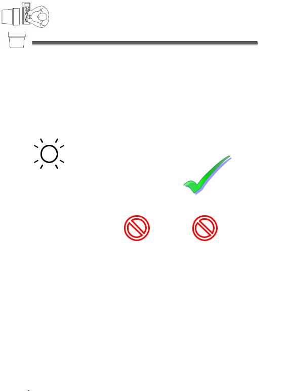
POSITIONING THE MONITOR
Ensure that the monitor is set up in such a way that reflections, glare and light/darkness contrast are avoided.
|
|
|
|
|
|
|
|
|
|
|
|
|
|
|
|
|
|
|
|
|
|
|
|
|
|
|
|
|
|
|
|
|
|
|
|
|
|
|
|
|
|
|
|
|
|
|
|
|
|
|
|
|
|
|
|
|
|
|
|
|
|
|
|
|
|
|
|
|
|
|
|
|
|
|
|
|
|
|
|
|
|
|
|
|
|
|
|
|
|
|
|
|
|
|
|
|
|
|
|
|
|
|
|
|
|
|
|
|
|
|
|
|
|
|
|
|
|
|
|
|
|
|
|
|
|
|
|
|
|
|
|
|
|
|
|
|
|
|
|
|
|
|
|
|
|
|
|
|
|
|
|
|
|
|
|
|
|
|
|
|
|
|
|
|
|
|
|
|
|
|
|
|
|
|
|
10 |
|
|
|
|
|
|
|
SETTING UP & GETTING STARTED |
|
|
|||||

0-15•
50-70 cm -(20-28 inches)-
0-15•
Hand rest: 2” – 4”
Top line of screen at eye level or slightly below Viewing distance: 20” – 27.5”
Legroom (vertical): minimum 25.5” Legroom (horizontal): minimum 23.6”
POSITIONING THE MONITOR
Operation Connecting Safety
Help
Appendix
11

WORKING IN COMFORT
Take regular breaks from the work at your screen to prevent tenseness and exhaustion.
Sitting in one position for long periods can be uncomfortable. To minimize the potential for physical discomfort or injury, it’s important that you maintain proper posture.
•Overall: Change your position frequently and take regular breaks to avoid fatigue.
•Back: While sitting at your work surface, make sure your back is supported by the chair’s backrest in erect position or angled slightly backwards.
•Legs: Your thighs should be horizontal or angled slightly downward. Your lower legs should be near a right angle to your thighs. Your feet should rest flat on the floor. If necessary, use a footrest, but double check that you have your seat height adjusted correctly before getting a footrest.
•Arms: Your arms should be relaxed and loose, elbows close to your sides, with forearms and hands approximately parallel to the floor.
•Wrists: Your wrists should be as straight as possible while using the keyboard, mouse or trackball. They should not be bent sideways, or more than 10 degrees up or down.
•Head: Your head should be upright or tilted slightly forward. Avoid working with your head or trunk twisted.
12 |
|
SETTING UP & GETTING STARTED |

SET-UP LOCATION
Keep your PC and all units connected to it away from moisture, dust, heat and direct sunlight. Failure to observe these instructions can lead to malfunctions or damage to the PC.
To prevent damage to your PC from a fall, place and operate the PC and all connected units on a stable, balanced and vi- bration-free surface.
AMBIENT TEMPERATURE
Connecting Safety
The PC can be operated at an ambient temperature of between 10° C and 35° C (+41° and +95° F) and at a relative humidity of between 30% and 70% (without condensation).
When powered off, the PC can be stored at temperatures between -20° C and 50° C (–40° and +158° F).
To provide additional protection against electric shock, power surges, lightning strikes, or other electrical damage to your PC, we recommend the use of a surge protector.
Wait until the PC has reached ambient (room) temperature before turning it on or connecting it to the power adapter. Drastic variations in temperature and humidity can create condensation within the PC and may cause it to short-circuit.
SET-UP LOCATION
Operation
Help
Appendix
13

14 |
|
SETTING UP & GETTING STARTED |
CONNECTING
For a better guidance, open up the left inner page of the cover with the diagrams to find the location of the described connections.
Note: The devices listed are not necessarily included with your PC.
CABLING
Please follow the instructions below in order to correctly connect your PC:
Arrange cables in such a way that no one can tread on or trip over them.
DO NOT place objects on the cables.
To avoid damage to your PC, connect your peripherals (e.g., keyboard, mouse and monitor) whilst your PC is powered off. Some devices can be connected whilst your PC is in use. These devices usually have a USB or IEEE 1394 connector. Please follow the appropriate instructions for each device.
Keep the PC at least one meter (approximately three feet) away from high frequency and magnetic interference sources
(e.g., televisions, loudspeaker cabinets, mobile telephones, etc.) in order to avoid malfunctions and/or loss of data.
To avoid EMC issues, make sure that all devices are connected to each cable or that cables not in use are removed from the computer.
Please note that only shielded cables shorter than
3 metres (9.84 ft) should be used for the LPT, COM, USB, IEEE 1394, audio, video and network interfaces with this PC.
The connection of devices is limited to equipment that complies with EN60950 “Safety of information technology equipment” or EN60065 “Audio, video and similar electronic apparatus. Safety requirements”.
Operation Connecting Safety
Help
Appendix
CABLING |
|
15 |
Note: You only need to connect those components to your computer you require. If you do not have the described device (e. g. printer) you may skip the respective item and carry it out later, if necessary.
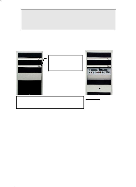
FRONT CONNECTORS
Here is how you can access the (optional) card reader and some further connectors on the front of your PC casing.
DVD-RW
DVD-ROM
Connect XL
Please press this button to slide down the cover.
DVD-RW
DVD-ROM
Connect XL
Push carefully the cover up to hide the card reader and the connectors.
(Diagram the same)
16 |
|
SETTING UP & GETTING STARTED |

CONNECTING THE MONITOR
Diagram reference: W, W2
If your graphics card has two VGA sockets), you can use either port to connect to the monitor. Your PC may optionally be equipped with a digital connector (DVI, W2). With the help of an adapter you can also use this connector for your VGA monitor.
•Because of its asymmetric form the plug only fits into the socket in one position.
1.Connect the data cable of the monitor to the socket on the graphics card (reference W or W2). If necessary, remove the white guard-ring on the monitor plug and ensure that the plug and socket mate together precisely.
2.Hand-tighten the screws on the monitor cable.
CAUTION! Your PC monitor is preconfigured for a screen resolution of 1024 x 768 pixels and an optimal refresh rate of 75 hz. If your monitor does not support these settings it may become damaged or malfunction during use.
You can change the screen resolution and configuration of your monitor as follows (See also your monitor's User Manual):
1.Once you have powered on the PC, press the F8 key to select Safe Mode.
If you don’t hit the F8 key on time, you won‘t see the start menu which gives you the option to run in Safe Mode. Reboot your PC and retry if you have missed this.
2.Select Display Properties to designate the screen resolution for your monitor.
You can then adjust the “Display Features” to your monitor.
CABLING
Operation Connecting Safety
Help
Appendix
17
INSTALLING WIRELESS KEYBOARD & MOUSE
These devices are optional. The wireless keyboard and mouse operate with digital radio technology to ensure no hinder communication between the keyboard, the mouse and your computer without connecting cable. The transmission and receiving of keyboard and mouse are free from angle restriction. Before working with your new keyboard and mouse, take a few one-time preparations.
Beware: Please read and follow the security advices concerning the use of batteries on page 82.
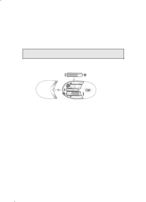
INSERTING BATTERIES IN MOUSE
The mouse requires two alkaline batteries (Type: AAA).
|
|
|
|
(Diagram the same) |
cover |
battery compartment |
|||
1.Remove the cover of the battery compartment of the mouse by pushing it in the direction of the arrow.
2.Insert the two alkaline batteries (AAA) in the battery compartment.
3.Slide the battery compartment cover open again .
18 |
|
SETTING UP & GETTING STARTED |
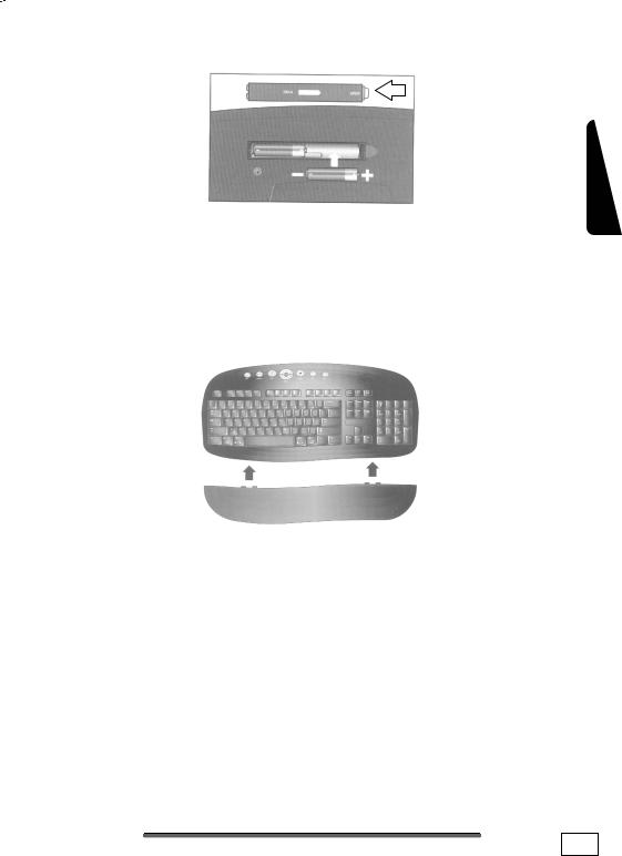
INSERTING BATTERIES IN KEYBOARD
(Similar picture)
The keyboard requires two alkaline batteries (AA).
1.Remove the battery compartment cover (1) on the bottom of the keyboard by pushing it in the direction of the arrow.
2.Insert two AA batteries. The illustration on the cover shows how to insert the batteries properly.
3.Recover the battery compartment.
CONNECTING THE PALM REST
Operation Connecting Safety
Help
1. Connect the palm rest to the keyboard.
CABLING
Appendix
19

CONNECTING THE RECEIVER
Diagram reference: E
1.Attach the USB receiver for the mouse and the keyboard to any free USB connection. It is recommended to use a connection at the back of the PC because of the visual appearance.
The distance between the reception station and the transmitter (keyboard and mouse) should not exceed 50 cm, in order to receive optimum wireless conditions.
Change the batteries if it is no longer possible to make entries smoothly.
The operation of the mouse and the keyboard is described on page 35.
Please proceed as described as follows if your computer is equipped with a cable-connected mouse/keyboard combination:
20 |
|
SETTING UP & GETTING STARTED |

CONNECTING A USB KEYBOARD
Diagram reference: E
1. Connect the USB keyboard to a USB port.
CONNECTING A USB MOUSE
Diagram reference: E
1. Connect the USB mouse to a USB port.
CONNECTING A PS/2 KEYBOARD
Diagram reference: PS2-1
Connect the keyboard to the left, purple PS/2 port.
If you want to connect a USB Keyboard please follow the instructions below.
CONNECTING A PS/2 MOUSE
Diagram reference: PS2-2
Connect the mouse cable to the right, green PS/2 port.
If you want to connect a USB mouse please follow the instructions below.
CONNECTING PARALLEL DEVICES
Diagram reference: P (optional)
Because of its asymmetric form the plug only fits into the socket in one position.
1.If you wish to connect a printer with a parallel (25-pin) connecting cable, connect the printer cable from your printer to the red printer socket P on the rear of your PC.
2.Hand-tighten the screws.
If you wish to use a scanner, which also connects to the PC via the parallel interface, follow the instructions above. With the PC parallel port in use, the printer can be connected directly to the scanner. You will have use of both devices if they are connected in this manner.
CABLING
Operation Connecting Safety
Help
Appendix
21

MODEM/ISDN CONNECTION
Diagram reference: Z
Your PC may be fitted with an analog modem or an ISDN card to prepare your PC for Internet excess and fax operation, according to the equipment.
MODEM
The modem cable has an RJ11 plug, which is plugged into the modem of your PC, and a TAE plug, which fits an N-coded, analogue telephone socket.
ATTENTION! Please observe that the modem may only be connected to an analogue telephone line. The connection of a digital system (ISDN etc.) to an analogue telephone line can possibly cause damage to the modem or the connected devices and the telecommunication network.
ISDN
The ISDN cable has RJ45 plugs at either end. It makes no difference which end is plugged into which socket.
1.Connect the matching plug of the enclosed communication cable to jack Z of your computer. Usually the jack is marked with “Line”.
2.Then connect the other plug to the telephone or ISDN outlet.
ATTENTION! Operate the ISDN unit only with digital telephone systems. This prevents an inadmissible operation possibly causing damage to the unit or the connected devices.
CONNECTING SERIAL DEVICES
Diagram reference: S (optional)
Because of its asymmetric form the plug only fits into the socket in one position. Hand-tighten the screws.
1.In order to connect an external modem, card reader or other serial device, connect the serial cable with the tur- quoise-coloured connection socket (S) on the rear of your PC.
22 |
|
SETTING UP & GETTING STARTED |

HAND-TIGHTEN THE SCREWS.LAN CONNECTION
Diagram reference: Q
According to the features your PC can be equipped with a network connection, in order to prepare it for network operation.
The network cable usually has two RJ45 plugs so that it is unimportant which plug is connected to which jack.
1.Connect the one plug of the cable to the PC jack.
2.Connect the other plug to the other PC or hub/switch.
For further information refer to chapter “The Network” starting at page 53.
CONNECTING SPEAKERS/AUDIO OUTPUT
Diagram reference: H, H2, H3, H4, U, U2
Connect your headphones or active speakers by plugging the cable with the 3.5 mm stereo jack plug into the green socket (reference H).
PCS WITH SURROUND SOUND
NOTE: You will find information about placing speakers by starting the sound software in the task bar
If your PC is equipped with it the following connection is required:
1.Connect the Front speaker to the green socket (reference H).
2.Connect your rear speaker to the Rear connector (H2).
3.Your centre speaker or subwoofer can be connected to the socket Centre/Subwoofer (H3).
4.Connect to the optional Back Surround socket (H4) two more speakers for the back surround.
5.In order to use the (optional) digital audio outlet plug the cinch cable in the jack at location U. The optical digital audio outlet is positioned at location U2. Connect the cable with an audio device with a digital cinch inlet according to the SPDIF standard.
CABLING
Operation Connecting Safety
Help
Appendix
23

CONNECTING A SOUND SOURCE/AUDIO INPUT
Diagram reference: J, J2, T, T2
This port is used to accommodate a connecting cable for external audio sources (i.e. stereo system, keyboard/synthesizer).
1.Connect the cable with the 3.5 mm stereo jack plug to the lightblue coloured socket (reference J). You can also connect a stereo Cinch cable (position J2).
2.If you want to record a digital audio source use the (optional) audio input T or T2. A SPDIF-Cinch cable will also be necessary for the T while T2 is an optical output.
CONNECTING A MICROPHONE
Diagram reference: I
1.You can use the pink socket I to connect a microphone with a 3.5 mm mono jack plug.
2.Position the microphone in such a way that it does not point directly at the speakers. If you hear feedback, characterised by loud whistling noises, reposition the microphone until the sound stops.
ANTENNA CONNECTION FOR TV / RADIO RECEIVER
Position in the flap-out overview: Y, Y2
Should your PC be equipped with a TV tuner card, then you must connect the corresponding 75 Ohm coaxial cables (aerial or cable) for radio and TV reception.
1.Connect the supplied radio antenna with the corresponding connector (Y) on the TV card.
2.Connect the TV connector on your TV card (Y2) with the aerial antenna or cable TV.
24 |
|
SETTING UP & GETTING STARTED |
 Loading...