


Leica MZAPO, MZ125, MZ95, MZ75, MZ6 User Manual
...Leica M-Series
Stereomicroscopes
User Manual
Contents
Page
Overview
Safety concept . . . . . . . . . . . . . . . . . . . . . . . . . . . . . . . . . . . . . . . . . . . . . . . . . . . . . . . . 4 Symbols . . . . . . . . . . . . . . . . . . . . . . . . . . . . . . . . . . . . . . . . . . . . . . . . . . . . . . . . . . . . . 5 Controls and functions . . . . . . . . . . . . . . . . . . . . . . . . . . . . . . . . . . . . . . . . . . . . . . . . . 6 Short instructions . . . . . . . . . . . . . . . . . . . . . . . . . . . . . . . . . . . . . . . . . . . . . . . . . . . . . 8
Use
Ergonomics . . . . . . . . . . . . . . . . . . . . . . . . . . . . . . . . . . . . . . . . . . . . . . . . . . . . . . . . . . 9 Viewing height and interpupillary distance . . . . . . . . . . . . . . . . . . . . . . . . . . . . . . . . 9 Eyepoint, eye contact . . . . . . . . . . . . . . . . . . . . . . . . . . . . . . . . . . . . . . . . . . . . . . . . . . 9 Changing the magnification . . . . . . . . . . . . . . . . . . . . . . . . . . . . . . . . . . . . . . . . . . . . 10 Focusing . . . . . . . . . . . . . . . . . . . . . . . . . . . . . . . . . . . . . . . . . . . . . . . . . . . . . . . . . . . . 11 Stereoscopic and axial observation . . . . . . . . . . . . . . . . . . . . . . . . . . . . . . . . . . . . . 12 Dioptric settings . . . . . . . . . . . . . . . . . . . . . . . . . . . . . . . . . . . . . . . . . . . . . . . . . . . . . . 12 Working with the stereomicroscope . . . . . . . . . . . . . . . . . . . . . . . . . . . . . . . . . . . . . 14
Assembly Basic outfit
Overview: Components . . . . . . . . . . . . . . . . . . . . . . . . . . . . . . . . . . . . . . . . . . . . . . . . 15 Spacer rings . . . . . . . . . . . . . . . . . . . . . . . . . . . . . . . . . . . . . . . . . . . . . . . . . . . . . . . . 16 Fitting the column to the incidentand transmitted-light bases . . . . . . . . . . . . . . . 18 Microscope carrier . . . . . . . . . . . . . . . . . . . . . . . . . . . . . . . . . . . . . . . . . . . . . . . . . . . 18 Binocular tubes, optics carrier, optical accessories . . . . . . . . . . . . . . . . . . . . . . . . 19 Graticules . . . . . . . . . . . . . . . . . . . . . . . . . . . . . . . . . . . . . . . . . . . . . . . . . . . . . . . . . . . 20
Stands
Transmitted-light stand, bright field, 20W . . . . . . . . . . . . . . . . . . . . . . . . . . . . . . . . . 20 Transmitted-light stands, bright and dark field . . . . . . . . . . . . . . . . . . . . . . . . . . . . . 22 Swinging-arm stand ESD . . . . . . . . . . . . . . . . . . . . . . . . . . . . . . . . . . . . . . . . . . . . . . 22 Large swinging-arm and table-clamp stands . . . . . . . . . . . . . . . . . . . . . . . . . . . . . . 24
Illuminators
Transformers . . . . . . . . . . . . . . . . . . . . . . . . . . . . . . . . . . . . . . . . . . . . . . . . . . . . . . . . 26 Leica L2 cold-light source . . . . . . . . . . . . . . . . . . . . . . . . . . . . . . . . . . . . . . . . . . . . . .27 Fibre-optic light guide . . . . . . . . . . . . . . . . . . . . . . . . . . . . . . . . . . . . . . . . . . . . . . . . . 28 Cold-light source Leica CLS Series . . . . . . . . . . . . . . . . . . . . . . . . . . . . . . . . . . . . . .28 Mains (line) lamp 25W . . . . . . . . . . . . . . . . . . . . . . . . . . . . . . . . . . . . . . . . . . . . . . . . 28 Incident lamp 6V/10W . . . . . . . . . . . . . . . . . . . . . . . . . . . . . . . . . . . . . . . . . . . . . . . . . 28 Incident lamp 6V/20W . . . . . . . . . . . . . . . . . . . . . . . . . . . . . . . . . . . . . . . . . . . . . . . . . 30 Coaxial illuminator . . . . . . . . . . . . . . . . . . . . . . . . . . . . . . . . . . . . . . . . . . . . . . . . . . . . 32 Near-vertical illuminator . . . . . . . . . . . . . . . . . . . . . . . . . . . . . . . . . . . . . . . . . . . . . . . 32
2
Page
Accessories
Fitting accessory tubes . . . . . . . . . . . . . . . . . . . . . . . . . . . . . . . . . . . . . . . . . . . . . . . . 33 Double-iris diaphragm . . . . . . . . . . . . . . . . . . . . . . . . . . . . . . . . . . . . . . . . . . . . . . . . . 33 Drawing tube . . . . . . . . . . . . . . . . . . . . . . . . . . . . . . . . . . . . . . . . . . . . . . . . . . . . . . . . 33 Video-phototubes: Photography, video, TV, filming, digital imaging . . . . . . . . . . . . 34 Attachment for vertical and oblique observation . . . . . . . . . . . . . . . . . . . . . . . . . . . 37 Stages, polarization . . . . . . . . . . . . . . . . . . . . . . . . . . . . . . . . . . . . . . . . . . . . . . . . . . . 37
Special notes
Tips and hints: What to do if … . . . . . . . . . . . . . . . . . . . . . . . . . . . . . . . . . . . . . . . . . 38 Care and maintenance of the stereomicroscope, maintenance . . . . . . . . . . . . . . 39 Calculating total magnification and field diameter . . . . . . . . . . . . . . . . . . . . . . . . . 40 Optical data, MS5, MZ6 . . . . . . . . . . . . . . . . . . . . . . . . . . . . . . . . . . . . . . . . . . . . . . . 41 Optical data, MZ75, MZ95 . . . . . . . . . . . . . . . . . . . . . . . . . . . . . . . . . . . . . . . . . . . . . . 42 Optical data, MZ125, MZAPO . . . . . . . . . . . . . . . . . . . . . . . . . . . . . . . . . . . . . . . . . . . 43 Dimensions . . . . . . . . . . . . . . . . . . . . . . . . . . . . . . . . . . . . . . . . . . . . . . . . . . . . . . . . . . 44
3
To you, the user
Thank you for your trust. We wish you success and satisfaction in your work with your new stereomicroscope from Leica.
The innovative technology of the new stereomicroscope line from Leica is expressed externally in the avant-garde form of the instrument. The rounded shapes, with their elliptical tendencies, demonstrate that beauty can be practical.
In developing this new stereomicroscope line we have placed great weight on simple, self-explanatory directions. We have however put a lot of effort into explaining all functions to you by means of pictures and text. You will only get the best out of your stereomicroscope if you take the trouble to study this user manual in detail.
If you still have a question sometime, just contact your local Leica agency or get in touch directly with Leica Microscopy Systems Ltd, Heerbrugg, Switzerland. We are gladly at your service. Customer service is a big thing with us. Not only before the sale, but afterwards as well.*
*The business units of Leica Microsystems hold
the management system certificates for the international standards ISO 9001 and ISO 14001 relating to quality management, quality assurance and environmental management.
Safety concept
General directions
Before you try to use the instrument, please read the user manual and the safety notes.
Permitted uses
The Leica MS5, MZ6, MZ75, MZ95, MZ125 and MZAPO stereomicroscopes are optical instruments which use magnification to see the finer details of objects close to the eye.
The objects may be either natural, or created by human agency. The basic outfit, which includes a stand and a light source,
can be supplemented with various modules for photography, TV, dual station viewing and other applications.
Prohibited uses
•The use of the instrument in a different manner from that described in this user manual can lead to injury, malfunction and damage.
•Do not fit different plugs. Do not dismantle optical systems or mechanical parts unless instructions for doing so are given in the user manual.
Place of use
•The Leica MS5, MZ6, MZ75, MZ95, MZ125 and MZAPO stereomicroscopes are intended mainly for indoor use.
•If the stereomicroscope is used outdoors, protect it from dirt and damp. Lamps and electrically-operated stands from Leica may not be used outdoors.
Use in ESD protected rooms
The optics carrier MS5, MZ6, MZ75, MZ95, MZ125, the binocular tube, ErgoTubus™, ErgoKeil™ 5°–25°, the swinging-arm stand ESD and the cold light sources Leica L2 and CLS consist of ESDdischarging material (surface resistance (<1011 ohms/squared, discharge time <2 seconds, 1,000V to 100V).
•A connection socket for a 4mm dia. earthing cable is provided on the microscope carrier.
•There are two connection sockets for 4mm dia. earthing cables in the base of the swinging-arm stand.
Servicing
Repairs may only be carried out by Leica-trained service technicians. Only original Leica spare parts may be used.
Responsibilities of person in charge of instrument
•Ensure that personnel who use the instrument have read and understood this user manual and in particular the safety instructions.
•Ensure that the Leica MS5, MZ6, MZ75, MZ95, MZ125 and MZAPO stereomicroscopes are operated, maintained and repaired only by authorized and trained personnel.
4

Safety regulations
Electrically-operated items
The safety regulations listed below apply to the following items:
–Transmitted-light stand, bright field, 20W (page 20)
–Mains lamp 25W (page 28)
–Regulating transformer 0–7V/40W (page 26)
–Step transformer 4/5/6V (page 26)
–Motor focus (separate instructions)
Liquids
Be careful when handling liquids. If spilt on the equipment, they can:
–cause the stereomicroscopes and accessories to become electrically live, endangering personnel
–cause damage to the equipment.
Power cables
Inspect cables regularly for damage. Defective cables can:
–directly endanger personnel
–cause the stereomicroscopes and accessories to become electrically live, endangering personnel.
Positioning cables
Position cables with care. Make sure that personnel do not get entangled with them. The instrument could fall over, fall down, become damaged, damage other equipment, or cause personal injury.
Opening the instrument
Only authorized Leica personnel are permitted to repair electrical equipment.
Before opening up the equipment, pull out the power cable.
If you touch the live interior of the equipment, you may receive an electric shock.
Grid voltage
Ensure that the voltage setting on the equipment is correct. A wrong setting can cause damage to the equipment.
Connections
When connecting power-consuming devices to the transformers, do not exceed the maximum permitted loading, as this can cause damage to the equipment.
Changing bulbs
•Before changing a bulb, disconnect the power cable.
•Never attempt to touch the inside of a lamp housing or transmitted-light stand while the instrument is connected to the power supply.
•Before changing a bulb, wait until it is cool, otherwise you may burn your fingers.
Legal requirements
Adhere to general and local regulations relating to accident prevention and environmental protection.
Conformity with European Community directive
The electrically-operated accessories for the Leica MS5, MZ6, MZ75, MZ95, MZ125 and MZAPO stereomicroscopes are constructed in accordance with the latest technologies and are provided with a statement of conformity with EC requirements.
You will find these symbols in the user manual:
Safety direction
This symbol denotes information which must be read and obeyed.
Failure to respect it can cause injury
Failure to respect it can cause malfunctioning, or damage to the equipment
Warning about accessible hot places, e.g. bulbs
Failure to respect it can cause burns
Important information
This symbol denotes additional information
or explanations which promote understanding.
Action
EThis symbol within the text indicates that certain operations must be carried out.
Explanatory notes
•This symbol within the text stands for additional information and explanations.
5

Overview
Standard outfit: Controls and functions
In this overview
we explain the controls and functions relating to the standard outfits.
Does your stereomicroscope look different from the one
in the picture?
The modular design enables you to assemble an outfit matched to the application. Controls and functions which differ from those in the standard outfit are described in the appropriate section (see contents list on page 2).
Leica MZAPO see page 8.
Stereomicroscope
1Magnification changer
Drive knobs with magnification scale. MS5: 5 steps
MZ6: 6:1 zoom MZ75: 7.9:1 zoom MZ95: 9.5:1 zoom MZ125: 12.5:1 zoom MZAPO: 10:1 zoom.
2Engaging ratchet positions
MZ6: Switch engages 7 magnification steps MZ75: Milled ring engages 8 magnification steps MZ95: Switch engages 9 magnification steps MZ125: Switch engages 10 magnification steps MZAPO: Switch engages 9 magnification steps.
3a Focusing drive
3b Coarse and fine focusing
Larger knob: Coarse focusing
Smaller knob: Fine focusing.
3c Adjustable ring
Changes the ease of movement of the coarse/fine drive.
4Clamping screw
Holds the optics carrier in the microscope carrier.
5Clamping screw
Holds the binocular tube (or accessory) to the optics carrier.
6Interchangeable objective
Various objectives (achromatic, planachromatic, planapochromatic), depending on the outfit.
Binocular tube
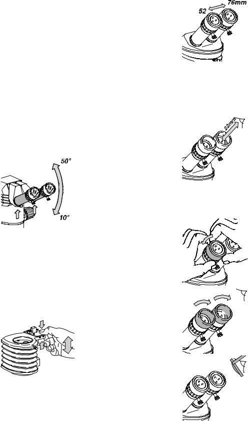
7Adjustable eyepiece tubes:
Interpupillary distance adjustable within the range 52mm – 76mm.
8Wide-field eyepieces for spectacle wearers
Dioptric setting adjustable within the range from +5 to –5, and eyecups adjustable.
9Clamping screws
These hold the eyepieces in the binocular tube.
10ErgoTube™
The viewing angle is adjustable within the range 10° – 50°.
Leica Design
by Ernest Igl / Christophe Apothéloz
MS5
8
9
7
5
1
4
6
3a
6

MZ6
8
9
7
5
4
6
MZ95
8
7
5
4
6
MZ75
8
7
5
1
2
4
6
3a
MZ125
8
7
10
5
4
6
2
1
3c
3b
1
2
3c
3b
7

Short instructions
Checklist
In this overview
we have summarized the working sequence. You will find detailed user instructions on the pages indicated.
MZAPO
8 |
|
|
|
|
|
|
|
|
|
|
|
|
|
|
|
|
|
|
|
|
|
|
|
|
|
|
|
|
|
|
|
|
|
9 |
|
|
|
|
|
|
|
|
|
|
|
|
|
|
|
|
|
|
|
|
|
|
|
|
|
|
|
|
|
|
|
|
|
7 |
|
|
|
|
|
|
|
|
|
|
|
|
|
|
|
|
|
|
|
|
|
|
|
|
|
|
|
|
|
|
|
||
10 |
|
|
|
|
|
|
|
|
|
|
|
|
|
|
|
|
|
|
|
|
|
|
|
|
|
|
|
|
|
|
|
|
|
5 |
|
|
|
|
|
|
|
|
|
|
|
|
|
|
|
2 |
|
|
|
|
|
|
|
|
|
|
|
|
|
|
|
||
|
|
|
|
|
|
|
||||||||||
|
|
|
|
|||||||||||||
|
|
|
|
|
|
|
|
|
1 |
|||||||
|
|
|
|
|
|
|
|
|
||||||||
|
|
|
|
|
||||||||||||
4 |
|
|
|
|
|
|
|
|
|
|
|
|
|
|
|
3b |
|
|
|
|
|
|
|
|
|
|
|
|
|
|
|
||
|
|
|
|
|
|
|
|
|
|
|
|
|
|
|
3c |
|
|
|
|
|
|
|
|
|
|
||||||||
|
|
|
|
|
|
|
|
|
|
|
|
|
|
|||
6 |
|
|
|
|
|
|
|
|
|
|
|
|
|
|
|
|
|
|
|
|
|
|
|
|
|
|
|
|
|
|
|
|
|
Inspect the cleanliness
ERemove dust and dirt from the instrument (page 39).
EClean: Optical accessories, glass stage plates, and any graticules used (page 39).
Only for variable ErgoModules™
E Adjust viewing height (page 9)
Only for photomicrographic outfits
ELever at position “VIS”.
EFor trinocular tube: Push diaphragm lever to the right.
EOpen double-iris diaphragm (position “OPEN”).
Adjust the interpupillary distance
E Using both hands, displace the eyepiece tubes (page 9).
Select the degree of eye contact
E Secure the eyecup in the position required (page 9).
Adjust the dioptric setting
EAdjust the dioptric setting precisely for each eyepiece (page 12).
Set the magnification required
E Turn the rotary knob to the desired magnification (page 10).
Focusing
E Look into the eyepieces and focus on the object (page 11).
•Only for coarse/fine drive:
Focus approximately with the large knob, and then accurately with the small knob.
EIf the focusing movement is too loose or too tight, adjust the ease of movement (page 11).
Adjust the depth of field
EAdjust the depth of field with the double-iris diaphragm (page 33).
Microscope carrier AX
EFor measuring, photography and polarization, engage the vertical beam path (page 12).
8
Use
Ergonomics, viewing height, interpupillary distance, eye contact
Ergonomics
The reasons why users often cannot work comfortably with the 45° tube are the differing heights of the outfits, the various accessories and working distances, and the fact that the same instrument is often used by several people of differing builds. This problem can be effectively solved by using the Leica ErgoModules™.
If you have problems with the viewing configuration on your stereomicroscope, ask your Leica consultant for the most ergonomic Leica solutions.
Viewing height, viewing angle
•The viewing height is correct when your head and back are comfortably positioned.
• On the ErgoTube™, the viewing angle is adjustable from 10° – 50°.
EHolding the eyepiece tubes at their bases, swing them up or down (see arrow).
ErgoModule™
•ErgoWedge™ 5° – 25°
•ErgoWedge™ ±15°
•ErgoModule™ 50mm
•The ErgoTube™ 45° has eyepiece tubes which are 65mm longer than the standard ones.
•ErgoModule™ 30mm – 120mm
• After several years, regreasing may be necessary. Send the ErgoModule™ to the Leica service workshop.
Interpupillary distance
•The interpupillary distance is correct when you see a single circular field when viewing with both eyes.
E Look into the eyepieces and use both hands to move the eyepiece tubes closer together or further apart.
Locating the eyepoint
•For 10×/21B wide-field eyepieces for spectacle wearers, the distance from eye to eyepiece is about 22mm.
•When you can see the entire field of view without restriction, you have found the correct position (eyepoint).
E To find the eyepoint, slowly bring your eyes closer towards the eyepieces.
Selecting the degree of eye contact
If you do not wear spectacles, and want closer contact to the eyepieces:
E Holding the diopter ring, turn the eyecup anticlockwise until it is released.
E Pull the eyecup upwards.
E Holding the diopter ring, turn the eyecup clockwise.
Spectacle wearers need the whole of the available distance. Move the eyecups to the lowest position.
9

Use
Magnification changer
MS5: 5 steps
MZ6: 6:1 zoom
MZ75: 7.9:1 zoom
MZ95: 9.5:1 zoom
MZ125: 12.5:1 zoom
MZAPO: 10:1 zoom
•Zoom means continuous change of magnification. Ratchets can be engaged for certain magnifications (see below).
Changing the magnification
•The magnification changer can be operated from either the right or the left.
E Look into the eyepieces.
E Focus on the object (page 11).
E Turn the magnification changer to the position required.
Ratchet steps
MZ6: 0.8, 1.0, 1.25, 1.6, 2, 2.5, 3.2
MZ75: 0.8, 1, 1.25, 1.6, 2, 2.5, 3.2, 4
MZ95: 0.8, 1, 1.25, 1.6, 2, 2.5, 3.2, 4, 5
MZ125: 1, 1.25, 1.6, 2, 2.5, 3.2, 4, 5, 6.3, 8
MZAPO: 10, 12.5, 16, 20, 25, 32, 40, 50, 63
•Engage the ratchets whenever magnifications need to be exactly reproducible.
EFor MZ6, MZ95, MZ125 and MZAPO: Press the switch.
EFor MZ75: Turn the knurled ring anticlockwise.
Scale of magnifications
MS5, MZ6
Display of magnification factors from 0.63 – 4.
MZ75
Display of magnification factors from 0.63 – 5. For other objectiveeyepiece combinations, appropriate adhesive scales can be applied to the rotary knobs (page 19).
MZ95
Display of magnification factors from 0.63 – 6.
MZ125
Display of magnification factors from 0.8 – 10.
MZAPO
Display of magnifications with various optical combinations, e.g. with 1.0× objective and 10× eyepieces: 8× – 80×.
MZAPO: Setting the scale
The magnification scale can be set in accordance with the optical combination.
Example:
1.0× objective / 25× eyepiece
ETurn the magnification changer to the stop at its lowest magnification position.
E Read the magnification range from the table on page 43 (in the example given, 20× to 200×).
E Place a finger in the rear window of the magnification changer and displace the scale so that the position 20 is lined up with the index.
Magnifications and fields of view
The tables between page 41 and page 43 provide information about the magnifications and field diameters as a function
of the magnification changer position of the eyepiece-objective combination used.
10
Magnification with MZ125/MZAPO Pan and Planapo objectives
When the MZ125/MZAPO planachromatic and planapochromatic objectives are used on the Leica MS5, MZ6, MZ75 and MZ95, the magnification is increased by the factor 1.25×. This factor
is taken into account in the tables.
Magnification on |
Magnification on |
MZ125/MZAPO |
MS5/MZ6/MZ75/MZ95 |
1.0× Plan/Planapo |
1.25× |
|
|
1.6× Planapo |
2.0× |
|
|
0.63× Planapo |
0.8× |
|
|
0.5× Plan |
0.63 |
|
|
0.8× Plan |
1.0× |
|
|
Setting the working distance, focusing = obtaining a sharp picture
•To focus, use the focusing drive to raise or lower the stereomicroscope until the feature of interest is in focus. The working distances of the various objectives are listed in the tables on pages 41–43.
•The focusing drive can be operated from either the right or the left.
E Place the object beneath the objective.
E Engage the lowest magnification (page 10).
E Look into the eyepieces.
EUsing the rotary knob, bring the object into focus.
Adjusting the free running of the focusing drive
Does the focusing drive run too loosely or too tightly, or does the equipment drift downwards?
You can match the ease of movement to the weight of the outfit and to your personal requirements.
Focusing drive
EGrip the drive knobs firmly with both hands and turn them in
opposite directions until you obtain the required degree of resistance during focusing
Focusing drive, coarse / fine
ETurn the black ring on the right-hand drive knob until you
obtain the required degree of resistance during focusing.
Only for coarse / fine drives
EFocus approximately with the larger knob.
EFocus accurately with the smaller knob.
11
Use
Microscope carrier: Turn optics carrier sideways, stereoscopic / axial observation
Microscope carrier for stereoscopic observation
This microscope carrier permits only stereoscopic observation, using both beam paths.
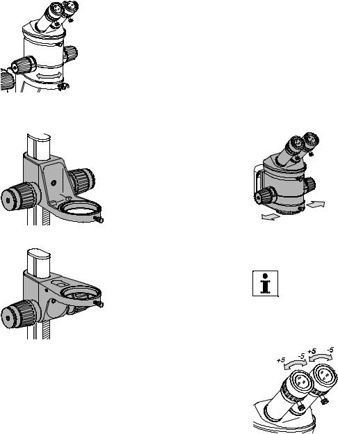
•The optics carrier can be turned sideways in the microscope carrier if the user needs to work from the side:
E Release the clamping screw.
E Turn the optics carrier sideways as required.
E Retighten the clamping screw.
The microscope carrier can be attached to the focusing drive in either of two positions:
•For short working distances and
1for flat objects, use Position 1. Use this position also in conjunction with the attachment for vertical and oblique observation
(see detailed instructions).
Microscope carrier AX
The stereomicroscopes can be equipped with the microscope carrier AX for stereoscopic and axial observation instead of the standard microscope carrier.
•The microscope carrier cannot be turned sideways when in the microscope carrier AX (see page 24).
•The microscope carrier AX can only be fitted in one position to the focusing drive (see page 18).
For the Leica MZ125 and Leica MZAPO, use the spacer ring (page 16).
Stereoscopic observation
A three-dimensional image is essential for studying and working on spatial objects.
E Shift the stereomicroscope to the central position.
Axial observation
The parallax-free imaging produces more precise results in photography, measuring and polarization.
E Shift the stereomicroscope to the left or the right position. The object is now located directly beneath either the left or the right beam path.
• When photographing or measuring, select the beam path above which the phototube or measuring graticule is located.
•Use Position 2 for long working
2 |
distances and for bulky objects. |
Adjusting the dioptric settings and the parfocality
You must adjust the dioptric settings for both eyes exactly as described on page 13. Only then will the image be parfocal, i.e. it will remain sharp whenever the magnification is changed and there will be no need to refocus. Make the most of this opportunity, which is not offered by every stereomicroscope.
For assembly, refer to page 18.
•The dioptric range is from +5 to –5.
12

The following adjustments must be carried out only once by each user.
The procedures for adjusting the dioptric setting and the parfocality are somewhat different if an eyepiece contains a graticule. Refer to the user manuals for the MPS modular photomicrographic systems or for measuring.
A Preparations
ESet up the illumination (pages 20–21, 26–32).
ESet the interpupillary distance and, if necessary, the viewing height (page 9).
EOn the video-/phototube: Move the lever to position “VIS” and open the diaphragm.
E Set the double-iris diaphragm to “OPEN” (page 33).
E Adjust the eyecups (page 9).
E Set both eyepieces to zero.
ESet the microscope carrier AX for stereoscopic observation.
B Focus on the test object
1. Flat test object
EPlace such an object beneath the objective.
2. Lowest magnification
E Engage the lowest magnification position (page 10).
EUse the coarse focusing drive to set the working distance (page 11).
3. Look into the eyepieces
EUsing the focusing drive, bring the test object into focus.
4. Highest magnification
E Engage the highest magnification position.
5. Image sharpness
E Optimize with focusing drive.
CAdjust the dioptric settings
6.Lowest magnification
EEngage the lowest magnification position.
7. Do not look into the eyepieces
E Rotate the eyepieces anticlockwise in the “+” direction as far as the stop (+5 diopters).
8. Look into the eyepieces
E Slowly rotate each eyepiece individually in the “–” direction until each eye sees the object sharply imaged.
D Inspect the parfocality
9. Highest magnification
E Engage the highest magnification position.
10. Refocus
E Refocus if necessary.
11. Magnification changer
ESlowly move the magnification changer from the lowest magnification to the highest.
•The image sharpness must
remain constant (parfocal). Otherwise, repeat the procedure.
13

Use |
• When focusing on a fresh object, always start with the |
|
lowest magnification, because the larger field of view makes |
||
|
||
Working with the stereomicroscope |
the object easier to find. Afterwards, select the magnification |
|
you want. |
||
|
||
In this section |
E Place the object beneath the |
|
objective. |
||
we will show you how to work smoothly with your stereomicro- |
E Illuminate the object. |
|
scope and how to study objects routinely. |
|
|
Preconditions for working comfortably |
|
•Pay great attention when setting up your stereomicroscope. You will only benefit fully from the outstanding optical and ergonomic advantages of the instrument if you set it up precisely in accordance with the directions already given.
•For fatigue-free work, use the ErgoModules™ (page 9).
•Arrange your workplace as well as possible, and pay attention to the heights of chair and table.
•When sitting, use the entire seat area and also the back support of the chair.
•Support your forearms.
•During work breaks, stand up and move around for exercise.
Tips for your work
The stereomicroscopes are parfocally matched. This means that, once you have focused on a feature in the manner described, taking account of dioptric settings (page 12), you can zoom the magnification up and down without refocusing. You only need to refocus if you want to look at higher or lower planes in the object.
ESelect the lowest magnification position.
EUsing the focusing drive, set the working distance approximately (page 11).
ELook into the eyepieces and use the focusing drive to bring the object precisely into focus.
ESelect the highest magnification position.
EUse the focusing drive to refocus.
Now the object should remain in focus at all zoom magnifications. Otherwise, check that your dioptric settings have been adjusted exactly as described on page 12.
14
Assembly
Basic outfit
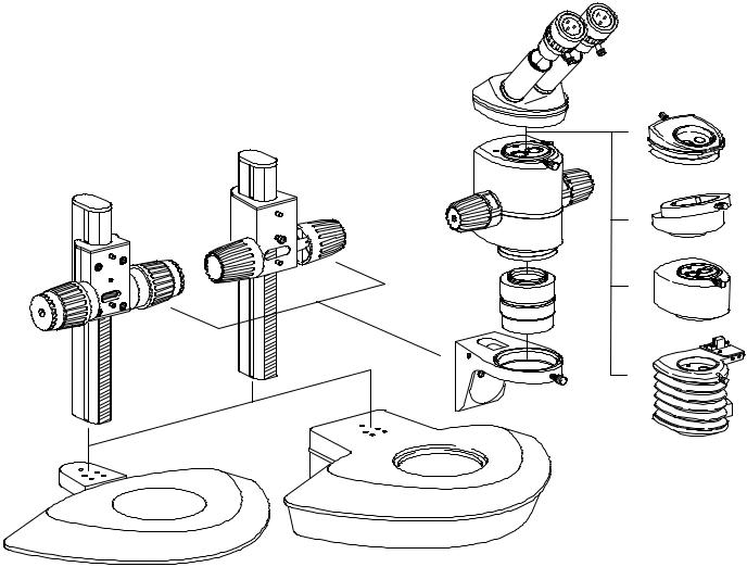
The components
1a Incident-light base with stage plate
1b Transmitted-light base with glass stage plate
2a Side-faced column with drive housing, coarse/fine
2b Side-faced column with drive housing
3Microscope carrier
4Optics carrier
5Interchangeable objective
6Binocular tube
7Wide-field eyepiece for spectacle wearers, with eyecups
8Various ErgoModules™ or accessories for video, photography, drawing, fluorescence, coaxial incident light etc.
2b
2a
1a
7
8
6
4
5
3
1b
15
 Loading...