


Leica M525 OH4
User manual
10 714 367 – version -

Thank you for purchasing a Leica surgical microscope system.
In developing our systems, we have placed great emphasis on simple, self-explanatory operation. Nevertheless, we suggest studying this user manual in detail in order to utilize all the benefits of your new surgical microscope.
For valuable information about Leica Microsystems products and services, and the address of your nearest Leica representative, please visit our website,
www.leica-microsystems.com
Thank you for choosing our products. We hope that you will enjoy the quality and performance of your Leica Microsystems surgical microscope.
Leica Microsystems (Schweiz) AG
Surgical Microscopy Business Unit
Leica M525 OH4 / Ref. 10 714 367 / Version -

|
Chapter overview |
Introduction |
3 |
Controls |
6 |
Preparation for operation |
21 |
Use |
37 |
Safety notes |
58 |
Care and maintenance |
68 |
What to do if...? |
73 |
Technical data |
77 |
Leica M525 OH4 / Ref. 10 714 367 / Version - |
1 |

Contents
|
screen |
Introduction |
|
User manual |
3 |
Product identification |
3 |
Symbols in this user manual |
3 |
Design |
4 |
Controls |
|
Leica M525 microscope with swing arm |
6 |
Control unit |
7 |
Terminals |
7 |
Stand |
8 |
CAN handles |
9 |
Mouth switch |
9 |
Footswitch |
9 |
Beam splitter |
17 |
Beam splitter with counterweight |
17 |
180° assistant’s attachment |
17 |
Ultra Observer Leica ULT500 |
17 |
Dual Imaging Color Module Leica DI C500 |
18 |
Stereoscopic co-observer tube |
18 |
Tubes |
18 |
Video and photo accessories for Leica M525 |
20 |
Preparation for operation |
|
Checklist: before the operation |
21 |
Installing optical accessories |
22 |
Setting the tube |
23 |
Setting the eyepiece |
24 |
Installing documentation accessories |
24 |
Selecting documentation accessories |
26 |
Stand settings |
27 |
Changing the weight disk on the D-axis |
33 |
Releasing the brakes |
34 |
Transport, transporting and rest positions |
35 |
Positioning on the operating table |
36 |
Attaching sterile controls |
36 |
Use |
|
Positioning the microscope |
37 |
Adjusting the microscope |
38 |
Control unit with touch panel |
43 |
Leica DI C500 |
52 |
Autofocus settings |
54 |
The Maintenance menu |
56 |
Microscope settings |
57 |
The "How to..." menu |
57 |
The Service menu |
57 |
|
screen |
Safety notes |
|
Intended use |
58 |
Directions for the person responsible for the |
|
instrument |
58 |
Directions for the operator of the instrument |
59 |
Dangers of use |
60 |
Manufacturer's declaration of electromagnetic |
|
compatibility (EMC) |
62 |
Signs and labels |
66 |
Care and maintenance |
|
Maintenance instructions |
68 |
Cleaning the touch panel |
68 |
Maintenance |
68 |
Changing bulbs |
69 |
Checking the timer for the xenon lamp |
69 |
Changing fuses |
70 |
Notes on reprocessing of |
|
resterilizable products |
71 |
Instructions |
71 |
What to do if...? |
|
General faults |
73 |
TV, photography |
75 |
Error messages on the control unit |
76 |
Technical data |
|
Electrical data |
77 |
Leica M525 |
77 |
Accessories |
77 |
IGS |
78 |
Fluorescence |
78 |
Floor stand |
78 |
Ambient conditions |
79 |
Standards fulfilled |
79 |
Limitations of use |
79 |
List of weights of balanceable configurations |
80 |
Dimensional drawings |
81 |
2 |
Leica M525 OH4 / Ref. 10 714 367 / Version - |

Introduction
User manual |
Symbols in this user manual |
In addition to instructions for use, this user manual also provides important safety notes (see the chapter entitled, "Safety notes").
Read the user manual carefully and thoroughly before placing the product in operation.
Product identification
The model code and serial number of your product are provided on the nameplate found on the illumination unit. Write this data into your user manual and always refer to it when you contact us or the service workshop regarding any questions you may have.
Model: |
Serial No.: |
The symbols used in this user manual have the following meanings:
Warning |
Warning regarding use hazard or |
|
improper use which can cause serious |
|
personal injury or death. |
Caution |
Warning regarding use hazard or |
|
improper use which can cause minor per- |
|
sonal injury, but considerable damage to |
|
property, assets and the environment. |
|
Useful information that can help the user |
|
operate the product correctly and |
|
efficiently. |
|
Call to action; here you are asked to do - |
|
something. |
Leica M525 OH4 / Ref. 10 714 367 / Version - |
3 |
Introduction
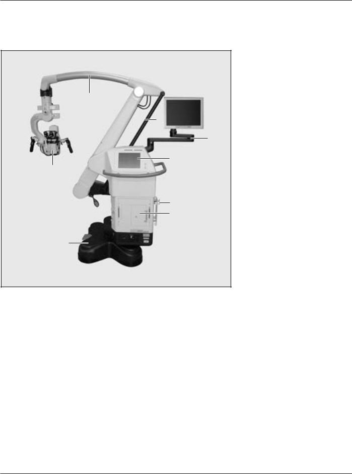
Design
surgical microscope Leica M525 OH4
1
2
3
4
8
5
6
7
1 |
Swing arm |
2 |
Tiebar |
3 |
Video monitor (optional) |
4 |
Control unit with touch panel |
5 |
Suspension device for footswitch |
6 |
Illumination unit |
7 |
Base |
8 |
Optical carrier Leica M525 |
4 |
Leica M525 OH4 / Ref. 10 714 367 / Version - |

Introduction
5 |
|
|
1 |
|
|
||||
|
|
|
|
|
4 |
|
2 |
||
|
||||
6
7
3
1 |
Vertical arm |
2 |
Terminals |
3 |
Footbrake |
4 |
Handle |
5 |
Articulated arm for monitor |
6 |
Camera control unit (optional) |
7 |
System unit Leica MDRS3 (optional) |
The Leica M525 with its open architecture, offers space for accommodating the video control unit and the Leica MDRS3.
Leica M525 OH4 / Ref. 10 714 367 / Version - |
5 |
Controls
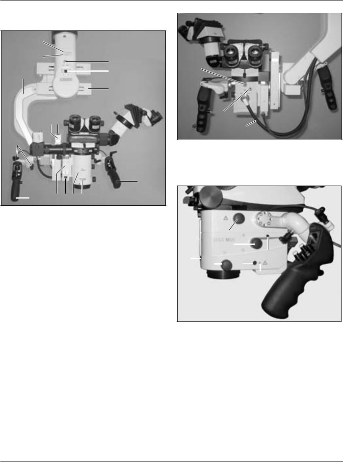
Microscope Leica M525 with swing arm
|
1 |
|
2 |
|
3 |
14 |
4 |
|
|
|
5 |
12 13
11
6
6 10 9 8 7
1Status LED for fluorescence
-LED lights up white = white light mode
-LED lights up blue = blue light mode
-LED lights up yellow = NIR mode
-LED lights up green = Playback mode
2Status LED for recording LED lights up red = recording in progress
3 |
Push-button for intraoperative AC/BC balancing |
4 |
Switch for manual balancing of the C-carriage |
5 |
C-carriage |
6 |
CAN handle |
7 |
Display of set working distance |
8 |
Optical carrier M525 |
9 |
Switch for manual balancing of the A-carriage |
10A-carriage
11CAN handle clamping lever
12Switch for manual balancing of the B-carriage
13B-carriage
14Swing mount
15
16
17
15CAN socket for accessories (DI C500, FL400)
16CAN socket (not used)
17Optical fiber
|
|
|
18 |
|
|
|
|
|
|
|
19 |
|
|
|
|
|
|
|
|
|
|
||
24 |
|
|
20 |
||||
|
|
|
22 |
|
|
||
23 |
|
|
|
||||
|
|
|
|||||
|
|
|
|
|
|
||
|
|
|
21 |
||||
18Rotary button for zoom adjustment
19Rotary button for illumination field diameter adjustment
20Reset button for zoom dependent illumination field diameter adjustment
21Status of multifocus LED
22Multifocus key
23Rotary button for focus adjustment
24Working distance display
6 |
Leica M525 OH4 / Ref. 10 714 367 / Version - |

Controls
Control unit
1
2
3
1 Touch panel
2 Push-button with illumination LED (on/off)
3 Push-button with LED for Auto Balance
Terminals
4 |
|
5 |
|
6 |
|
7 |
|
8 |
|
9 |
|
10 |
4 AD.F. Additional Function 2
5 AD.F. Additional Function 1
6 Footswitch or handswitch 2
7 Footswitch or handswitch 1
8 Internal CAN
9 External CAN
10 External CAN
AD.F. 1 and 2 are digital relay outputs that can switch 24V/2A.
11
12
23
13
22
14
21
15
20
16
19 |
17 |
18
11 |
Storz light source |
18 |
for Sony NIR camera |
12 |
UV camera Hitachi |
19 |
Leica MDRS3 |
13 |
BNC IN (2x) |
20 |
SVGA IN 3 |
14 |
BNC OUT |
21 |
SVGA IN 2 |
15 |
S-Video IN (2x) |
22 |
SVGA IN 1 |
16 |
S-Video OUT |
23 |
SVGA OUT to Leica DI C500 |
17 |
Storz footswitch |
|
|
24 25 26
24S-Video adapter
25BNC adapter
26Ethernet adapter
Terminals 24, 25 and 26 are adapters which can be used to lead out the terminals of the optional Leica MDRS3 system unit or a camera control.
Leica M525 OH4 / Ref. 10 714 367 / Version - |
7 |
Controls
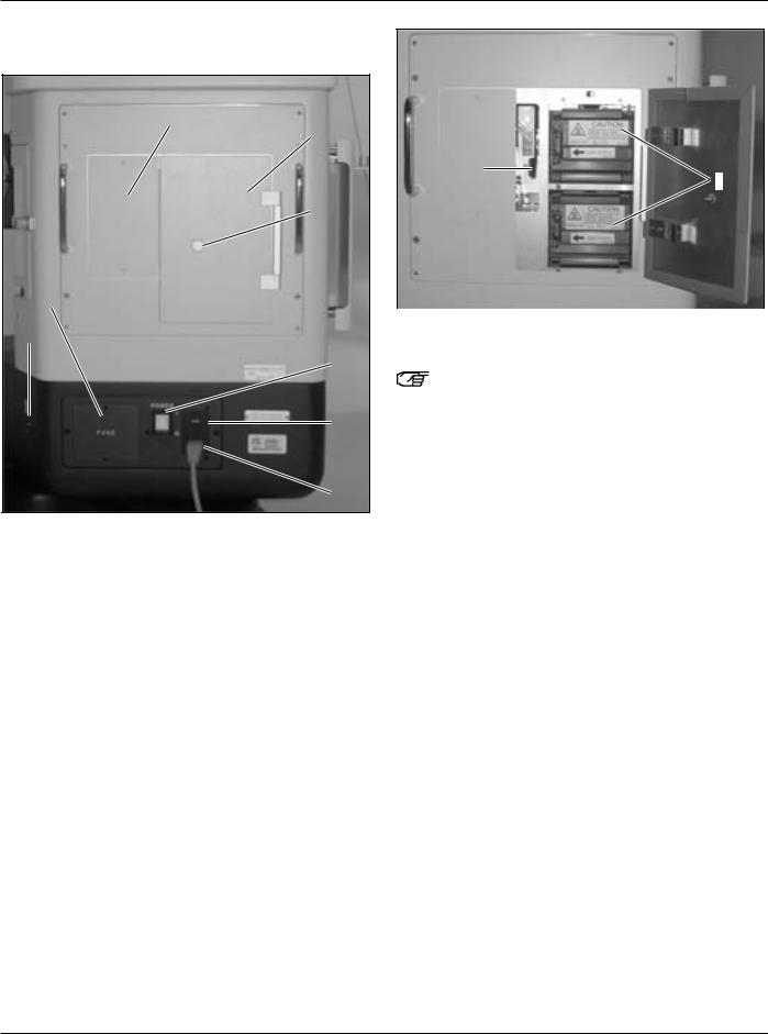
Stand
1
2
10
9
3
|
8 |
|
|
7 |
9 |
Lamp inserts for main illumination or backup illumination |
|
|
10 |
Lever for switching to standby illumination |
|
|
4 |
|
The Leica M525 OH4 surgical microscope has a |
|
|
|
|
|
|
|
primary illumination source and an equivalent standby |
|
5 |
|
illumination source. |
|
|
|
|
6
1 Illumination unit
2 Access door
3 Screw knob
4 Master switch for Leica M525 OH4 surgical microscope
5 Selector switch 100V/120V/220V/240V
6 Power supply
7 Potential equalization socket
8 Fuse box flap
8 |
Leica M525 OH4 / Ref. 10 714 367 / Version - |
Controls
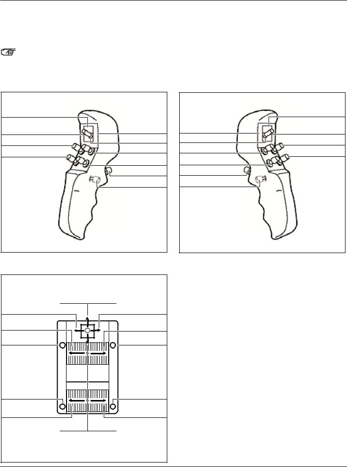
CAN handles |
Mouth switch |
|
2 |
6
1 |
3 |
4
5
|
|
|
6 Release preselected brakes |
|
|
|
|
1 |
Zoom |
||
2 |
4-function joystick |
||
3 |
Focus |
||
4 |
Release All Brakes |
||
5 |
Release preselected brakes |
||
You can assign switches 1, 2, 3 and 5 of the CAN handles individually for each user in the configuration menu (see page 50).
Footswitch
Here you will find an overview of the footswitches which you can use to control your Leica M525 surgical microscope.
Footswitches can be assigned individually for each user in the configuration menu (see page 48).
|
|
|
|
Footswitch |
|
Footswitch |
Footswitch |
|
|
|
|
Footswitch |
|
|||||||||||||||||||||||||||||||||||||||||||||||||||||||||||||||||||||||||||||||||||||||||||||||||||||
|
|
|
|
12 functions crosswise |
|
16 functions crosswise |
12 functions lengthwise |
|
|
|
|
16 functions lengthwise |
|
|||||||||||||||||||||||||||||||||||||||||||||||||||||||||||||||||||||||||||||||||||||||||||||||||||||
|
|
|
|
|
|
|
|
|
|
|
|
|
|
|
|
|
|
|
|
|
|
|
|
|
|
|
|
|
|
|
|
|
|
|
|
|
|
|
|
|
|
|
|
|
|
|
|
|
|
|
|
|
|
|
|
|
|
|
|
|
|
|
|
|
|
|
|
|
|
|
|
|
|
|
|
|
|
|
|
|
|
|
|
|
|
|
|
|
|
|
|
|
|
|
|
|
|
|
|
|
|
|
|
|
|
|
|
|
|
|
|
|
|
|
|
|
|
|
|
|
|
|
|
|
|
|
|
|
|
|
|
|
|
|
|
|
|
|
|
|
|
|
|
|
|
|
|
|
|
|
|
|
|
|
|
|
|
|
|
|
|
|
|
|
|
|
|
|
|
|
|
|
|
|
|
|
|
|
|
|
|
|
|
|
|
|
|
|
|
|
|
|
|
|
|
|
|
|
|
|
|
|
|
|
|
|
|
|
|
|
|
|
|
|
|
|
|
|
|
|
|
|
|
|
|
|
|
|
|
|
|
|
|
|
|
|
|
|
|
|
|
|
|
|
|
|
|
|
|
|
|
|
|
|
|
|
|
|
|
|
|
|
|
|
|
|
|
|
|
|
|
|
|
|
|
|
|
|
|
|
|
|
|
|
|
|
|
|
|
|
|
|
|
|
|
|
|
|
|
|
|
|
|
|
|
|
|
|
|
|
|
|
|
|
|
|
|
|
|
|
|
|
|
|
|
|
|
|
|
|
|
|
|
|
|
|
|
|
|
|
|
|
|
|
|
|
|
|
|
|
|
|
|
|
|
|
|
|
|
|
|
|
|
|
|
|
|
|
|
|
|
|
|
|
|
|
|
|
|
|
|
|
|
|
|
|
|
|
|
|
|
|
|
|
|
|
|
|
|
|
|
|
|
|
|
|
|
|
|
|
|
|
|
|
|
|
|
|
|
|
|
|
|
|
|
|
|
|
|
|
|
|
|
|
|
|
|
|
|
|
|
|
|
|
|
|
|
|
|
|
|
|
|
|
|
|
|
|
|
|
|
|
|
|
|
|
|
|
|
|
|
|
|
|
|
|
|
|
|
|
|
|
|
|
|
|
|
|
|
|
|
|
|
|
|
|
|
|
|
|
|
|
|
|
|
|
|
|
|
|
|
|
|
|
|
|
|
|
|
|
|
|
|
|
|
|
|
|
|
|
|
|
|
|
|
|
|
|
|
|
|
|
|
|
|
|
|
|
|
|
|
|
|
|
|
|
|
|
|
|
|
|
|
|
|
|
|
|
|
|
|
|
|
|
|
|
|
|
|
|
|
|
|
|
|
|
|
|
|
|
|
|
|
|
|
|
|
|
|
|
|
|
|
|
|
|
|
|
|
|
|
|
|
|
|
|
|
|
|
|
|
|
|
|
|
|
|
|
|
|
|
|
|
|
|
|
|
|
|
|
|
|
|
|
|
|
|
|
|
|
|
|
|
|
|
|
|
|
|
|
|
|
|
|
|
|
|
|
|
|
|
|
|
|
|
|
|
|
|
|
|
|
|
|
|
|
|
|
|
Leica M525 OH4 / Ref. 10 714 367 / Version - |
9 |

Controls
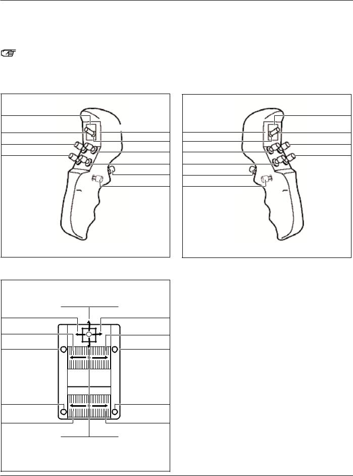
Presets "Cranial"/"Spine"/"ENT"
Here you will find an overview of the assignments of the CAN handles and an optionally connected footswitch for the preset user "Cranial"/"Spine"/"ENT".
You can assign CAN handles and footswitches individually for each user in the configuration menu (see pages 48 and 50).
Y+ |
|
|
|
Y+ |
X- |
X+ |
|
X- |
X+ |
Zoom + |
Y- |
|
Y- |
Zoom + |
Focus + |
|
|
||
Zoom - |
|
Focus + |
Zoom - |
|
|
|
|
||
|
Focus - |
|
Focus - |
|
|
All Brakes |
|
All Brakes |
|
|
Selected brakes |
|
Selected brakes |
|
|
|
|
|
|
|
Y+ |
X- |
X+ |
Focus + |
Focus - |
No function |
No function |
No function |
No function |
Zoom + |
Zoom - |
|
Y- |
10 |
Leica M525 OH4 / Ref. 10 714 367 / Version - |
Controls
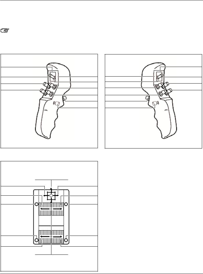
Preset "Image Injection IGS DI C500"
Here you will find an overview of the assignments of the CAN handles and an optionally connected footswitch for the preset user "Image Injection IGS DI C500".
You can assign CAN handles and footswitches individually for each user in the configuration menu (see pages 48 and 50).
IGS 3
IGS 4
Zoom +
Zoom -
IGS 2
IGS 1
Focus +
Focus -
All Brakes
Selected brakes
X-
Y-
Focus +
Focus -
All Brakes
Selected brakes
Y+
X+
Zoom +
Zoom -
|
Y+ |
X- |
X+ |
Focus + |
Focus - |
IGS 3 |
IGS 2 |
IGS 4 |
IGS 1 |
Zoom + |
Zoom - |
|
Y- |
Leica M525 OH4 / Ref. 10 714 367 / Version - |
11 |
Controls
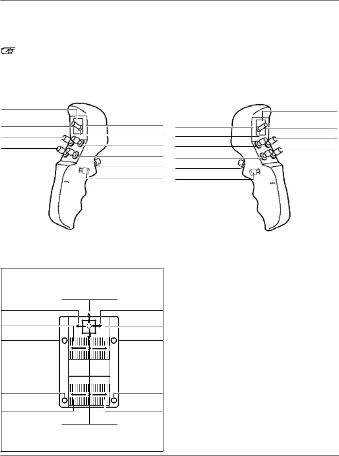
Preset "Image Injection ENDO DI C500"
Here you will find an overview of the assignments of the CAN handles and an optionally connected footswitch for the preset user "Image Injection ENDO DI C500".
You can assign CAN handles and footswitches individually for each user in the configuration menu (see pages 48 and 50).
No function
DI C500: Display on/off
Zoom +
Zoom -
DI C500:Shutter control
No function
Focus +
Focus -
All Brakes
Selected brakes
X-
Y-
Focus +
Focus -
All Brakes
Selected brakes
Y+
X+
Zoom +
Zoom -
|
Y+ |
X- |
X+ |
Focus + |
Focus - |
DI C500: |
DI C500: |
Display on/off |
Shutter control |
No function |
No function |
Zoom + |
Zoom - |
|
Y- |
12 |
Leica M525 OH4 / Ref. 10 714 367 / Version - |

Preset "Fluorescence Vascular FL800"
Here you will find an overview of the assignments of the CAN handles and an optionally connected footswitch for the preset user "Fluorescence Vascular FL800".
You can assign CAN handles and footswitches individually for each user in the configuration menu (see pages 48 and 50).
FL800 NIR Zoom Reset
FL800 Mode on/off
Zoom +
Zoom -
MDRS3 FL: Playback&Enter
MDRS3 FL:Menu&Down
Focus +
Focus -
All Brakes
Selected brakes
X-
Y-
Focus +
Focus -
All Brakes
Selected brakes
|
Y+ |
X- |
X+ |
Focus + |
Focus - |
FL800 Mode on/off |
FL800 NIR |
|
Zoom Reset |
MDRS3 FL:Menu&Down |
MDRS3 FL: |
|
Playback&Enter |
Zoom + |
Zoom - |
|
Y- |
Controls
Y+
X+
Zoom +
Zoom -
Leica M525 OH4 / Ref. 10 714 367 / Version - |
13 |
Controls
Preset "Fluorescence Oncology FL400"
Here you will find an overview of the assignments of the CAN handles and an optionally connected footswitch for the preset user "Fluorescence Oncology FL400".
You can assign CAN handles and footswitches individually for each user in the configuration menu (see pages 48 and 50).
No function
FL400 Mode on/off
Zoom +
Zoom -
No function
No function
Focus +
Focus -
All Brakes
Selected brakes
X-
Y-
Focus +
Focus -
All Brakes
Selected brakes
Y+
X+
Zoom +
Zoom -
|
Y+ |
X- |
X+ |
Focus + |
Focus - |
FL400 Mode on/off |
No function |
No function |
No function |
Zoom + |
Zoom - |
|
Y- |
14 |
Leica M525 OH4 / Ref. 10 714 367 / Version - |

Preset "Fluorescence Oncology FL400 & IGS DI C500"
Here you will find an overview of the assignments of the CAN handles and an optionally connected footswitch for the preset user "Fluorescence Oncology FL400 & IGS DI C500".
You can assign CAN handles and footswitches individually for each user in the configuration menu (see pages 48 and 50).
IGS 3 |
|
IGS 4 |
IGS 2 |
Zoom + |
IGS 1 |
|
|
Zoom - |
Focus + |
|
|
|
Focus - |
|
All Brakes |
|
FL400 Mode on/off |
X-
Y-
Focus +
Focus -
All Brakes
Selected brakes
|
IGS 3 |
IGS 4 |
IGS 2 |
Focus + |
Focus - |
FL400 Mode on/off |
No function |
No function |
No function |
Zoom + |
Zoom - |
|
IGS 1 |
Controls
Y+
X+
Zoom +
Zoom -
Leica M525 OH4 / Ref. 10 714 367 / Version - |
15 |
Controls
Preset "Fluorescence Oncology FL400 & Vascular FL800"
Here you will find an overview of the assignments of the CAN handles and an optionally connected footswitch for the preset user "Fluorescence Oncology FL400 & Vascular FL800".
You can assign CAN handles and footswitches individually for each user in the configuration menu (see pages 48 and 50).
FL800 NIR Zoom Reset |
|
|
|
|
|
|
Y+ |
|
|
|
|
|
|
|
|
FL800 Mode on/off |
|
MDRS3 FL: Playback&Enter |
|
X- |
X+ |
||
|
|
|
|
|
|||
|
|
|
|
|
|
Y- |
|
Zoom + |
|
MDRS3 FL: Menu&Down |
|
Zoom + |
|||
|
Focus + |
|
Focus + |
||||
Zoom - |
|
|
Zoom - |
||||
|
|
|
|
|
|
||
|
|
Focus - |
|
Focus - |
|
||
|
|
All Brakes |
|
All Brakes |
|
||
|
|
FL400 Mode on/off |
|
Selected brakes |
|
||
|
|
|
|
|
|
|
|
|
FL800 NIR Zoom Reset |
FL400 Mode on/off |
MDRS3 FL: Playback&Enter |
Focus + |
Focus - |
FL400 Mode on/off |
No function |
No function |
No function |
Zoom + |
Zoom - |
|
MDRS3 FL: Menu&Down |
16 |
Leica M525 OH4 / Ref. 10 714 367 / Version - |

Controls
A comprehensive range of accessories enables the |
180° second observer attachment |
|
Leica M525 OH4 surgical microscope to be matched to the |
|
|
requirements of the task in hand. Your Leica representative will |
|
|
|
|
|
be pleased to help you select the appropriate accessories. |
|
|
Beam splitter |
|
|
|
|
|
• Allows a second observer to view the procedure
Ultra Observer Leica ULT500
•Can be used for co-observation or documentation
Light distribution: 50% on each side (mono) or 30% / 70%
Beam splitter with counterweight
ULT |
500 |
|
LEICA
VIDEO
• Beam splitter with eight optical ports
• Light distribution:
Surgeon (front) 40% (stereo) Assistant (rear) 40% (stereo) or Assistant (side) 40% (mono) Documentation (side) 20%
•Can be used for co-observation or documentation Light distribution: 50% on each side (mono)
Leica M525 OH4 / Ref. 10 714 367 / Version - |
17 |

Controls
Dual Imaging Color Module Leica DI C500 Stereo attachment for second observer
VIDEO
• Is attached to the side outputs of a beam splitter.
•Beam splitter with eight optical ports
•Integrated color display shows data or video images.
•Light distribution:
Surgeon (front) 40% (stereo) Assistant (rear) 40% (stereo) or Assistant (side) 40% (mono) Documentation (side) 20%
18 |
Leica M525 OH4 / Ref. 10 714 367 / Version - |

Controls
Tubes
Binocular tube variable from 30°–150°
•Variable viewing angles from 30° to 150°
•Adjustable viewing height
•Adjustable interpupillary distance
Binocular tube variable from 0°–180°
• Variable viewing angles from 0° to 180°
Inclined binocular tube
Straight binocular tube
Inclined binocular tube 45°
Leica M525 OH4 / Ref. 10 714 367 / Version - |
19 |

Controls
Video and photo accessories for Leica M525
8 |
|
|
8 |
|
|
|
|
|
|
|
7 |
|
|
|
|
|
3 |
1 |
2 |
3 |
4 |
5 |
6 |
1 Leica 2D Pick up
2 Photo/TV dual attachment
3 Photo camera
4 TV attachment
Leica 2D pick-up
• Video system for recording 2D video sequences.
Leica 2D C-Mount
•Video system for recording 2D video sequences.
•The camera (8) is mounted on the TV attachment or Zoom Video Adapter.
Photo/TV dual attachment
•For using a video camera with C-mount at the same time as an SLR camera.
Complete with adapters.
•Position of video camera engageable in 45° increments.
•Video port with incorporated brightness adjustment (3 positions).
5 |
Zoom Video Adapter |
6 |
Phototube |
7 |
Video camera (such as the Leica D2D V3) |
8 |
Leica 2D C-Mount |
TV attachment
•For commercially-available video cameras with C-mount, complete with adapter.
•The TV attachment (4) is installed at the documentation port of the 0° assistant’s attachment.
•Position of video camera engageable in 90° increments.
Zoom Video Adapter
•For commercially-available video cameras with C-mount, complete with adapter.
•The Zoom Video Adapter (5) is installed at the documentation port of the 0° assistant’s attachment.
•Zoom and fine focus function for Leica Zoom Video Adapter
Phototube
•Complete with adapter, for SLR cameras.
•Adapter f = 250mm: for large fields of view and short expo-
sure times.
•Adapter f = 350mm: for high magnifications.
•The phototube (6) is mounted on the documentation port of the 0° assistant’s attachment.
20 |
Leica M525 OH4 / Ref. 10 714 367 / Version - |

Preparation for operation
Checklist: Before the operation
Cleaning the optical accessories
Check the tubes, eyepieces and the documentation accessories (if used) for cleanliness.
Remove dust and dirt (see page 68).
Installing accessories
Lock the Leica M525 OH4 in place and install all accessories on the microscope so it is ready for use (see page 22).
Position the CAN handles as required.
Connect a mouth switch and/or footswitch (if used).Check the camera image on the monitor and realign if
necessary.
Checking tube settings
Check the tube and eyepiece setting for the selected user (see page 24).
Treat the eyepieces with an antifogging compound if necessary.
Balancing
Balancing the Leica M525 OH4 (see page 27).
Press the "All Brakes" button on the CAN handle and check the balancing.
Function check
Warning 1
Danger of fatal electrical shock.
The Leica M525 OH4 surgical microscope may be connected to a grounded socket only.
Connect the power cable.Switch on the microscope.
Switch on the illumination at the control unit.
Leave the illumination on for at least 5 minutes, as otherwise luminosity will decrease rapidly.
Replace defective bulbs before the operation begins.Test all functions on the CAN handles and on the footswitch.Check the user settings on the control unit for the selected
user (see page 45).
Positioning at the OP table
Position the surgical microscope on the OP table as required, and lock the footbrake (see page 35).
Sterility
Fit sterile components and sterile drape if used (see page 36).
Warning 2
Danger of fatal electric shock
Operate the system only with all equipment in its proper position (all covers fitted, doors closed).
Leica M525 OH4 / Ref. 10 714 367 / Version - |
21 |
Preparation for operation
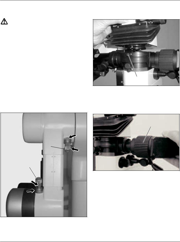
Installing optical accessories
Warning 3
Risk of injury through surgical microscope moving down!
Complete all preparations and adjustments to the stand before the operation.
Never balance or re-equip the instrument over the field of operation.
Always lock the Leica M525 OH4 in position before reequipping it.
Balance the Leica M525 OH4 after re-equipping it.Do not release the brakes when the instrument is in an
unbalanced state.
Locking the Leica M525 OH4 in position
The D-axis of the Leica M525 OH4 is locked in position with the locking device.
The locking device is principally for installation and re-equipping the Leica M525 OH4.
Pull out the locking buttons (1 and 2) and turn them until the two points (arrows) are aligned above each another.
2
1
Installing the 90° stereo attachment, binocular tube and beam splitter
3
Release the clamping screw (3).
Insert the accessories into the dovetail ring from above.Tighten the clamping screw (3).
Installing the stereo attachment for second observer
4
Insert the stereo attachment and check whether the connection has engaged.
Tighten the locknut (4) by hand.
Align the attachment for second observer as required.
Move the swing arm up and down until locking device (1) engages.
Move the swing arm back and forth until locking device (2) engages.
22 |
Leica M525 OH4 / Ref. 10 714 367 / Version - |

Preparation for operation
Setting the tube
Set the interpupillary distance
Adjust the interpupillary distance to a value between 55mm and 75mm.
2 |
1 |
|
|
Using the adjusting wheel (1), set the interpupillary distance such that a circular image field can be seen.
This procedure has to be performed only once for each user.
The acquired value (2) can be stored for each user on the "User
Settings" menu screen under "Tube Settings" (see page 51).
Adjusting the tilt
Hold the tube with both hands.Tilt the tube up or down.
|
|
|
|
|
|
|
|
|
|
|
|
|
|
|
|
|
|
|
|
|
|
|
|
|
|
|
|
|
|
|
|
|
|
|
|
|
|
|
|
|
|
|
|
|
|
|
|
|
|
|
|
|
|
|
|
|
|
|
|
|
|
|
|
|
|
|
|
|
|
|
|
|
|
|
|
|
|
|
|
|
|
|
|
|
|
|
|
|
|
|
|
|
|
|
|
|
|
|
|
|
|
|
|
|
|
|
|
|
|
|
|
|
|
|
|
|
|
|
|
|
|
|
|
|
|
|
|
|
|
|
|
|
|
|
|
|
|
|
|
|
|
|
|
|
|
|
|
|
|
|
Leica M525 OH4 / Ref. 10 714 367 / Version - |
23 |
|||

Preparation for operation
Setting the eyepiece
Determine/set the diopters for the user
The individual diopters can be adjusted continuously for each eyepiece from +5 to -5. Only this method will ensure that the image will stay in focus within the entire zoom range = parfocal. The treatment microscope ensures a high degree of fatigue resistance when the diopter setting is correct for both eyes.
A parfocal adjusted microscope ensures that the assistant´s view and monitor image will always remain sharp.
Set to the minimum magnification.
Place a flat test object with sharp contours under the lens at working distance.
Focus the microscope.
Set to the maximum magnification.
Focus the microscope.
Set to the minimum magnification
 Rotary ring for adjusting


 the diopters
Without looking into the eyepieces, turn both eye lenses to +5 diopters.
Slowly turn the eyepieces towards -5 individually for each eye until the test object appears sharp.
Select the highest magnification and check the sharpness.
This procedure has to be performed only once for each user. The acquired values can be stored for each user on the "User Settings" menu screen under "Tube Settings" (see page 51).
Adjusting the pupillary distance
Eyecup
Rotate the eyecups up or down until the desired distance is set.
Checking parfocality
Place a flat test object with sharp contours under the lens at working distance.
Zoom through the whole range, observing the test object. The image sharpness must remain constant at all magnifications. If this is not the case, check diopter settings of the eyepieces.
Installing documentation accessories
Fitting the Leica 2D
See user manual Leica 2D (10708979).
Fitting the photo/TV dual attachment
Install the dual attachment on the beam splitter.
Equip the video camera (1) with the TV objective (2) and insert into the dual attachment.
Tighten the clamping screw.
Loosen the clamping screw and engage the video camera until it engages in one of the 45° increments depending on the available space.
Tighten the clamping screw.
Equip the photo camera (5) with camera adapter (4).Screw the photo lens onto the camera adapter (4).Fit the camera to the dual attachment.
Tighten the clamping screw.
1
2
|
|
|
|
|
|
|
|
|
|
|
|
|
|
|
|
|
|
|
|
|
|
|
|
|
|
|
|
|
|
|
|
|
|
|
|
|
|
|
|
|
|
|
|
|
|
|
|
|
|
|
|
|
|
|
|
|
|
|
|
|
|
|
|
|
|
|
|
5 |
|
4 |
|
3 |
||||||||||||
1 Video camera
2 TV lens
3 Adapter M600 to M500 interface
4 Camera adapter
5 Photo camera and photo lens
The object image at the camera output is laterally reversed!
24 |
Leica M525 OH4 / Ref. 10 714 367 / Version - |

Preparation for operation
Using the dial, the brightness of the video can be adjusted to 30%, 50% or 100%. One of these filters can be switched with the 8% filter provided. To do so, remove the camera and change the filter in the TV output.
TV attachment / zoom video adapter
Mount the TV attachment on the documentation port of the beam splitter.
Screw the adapter to the camera using the C-mount.Insert the camera with the adapter into the TV attachment
and tighten the clamping screw.
 Video camera
 C-mount adapter


 Clamping screw
TV attachment
90¡ click-stop (TV attachment only):Loosen the clamping screw.
Engage the camera at one of the 90¡ increments in accordance with the space available and tighten the clamping screw.
Setting the Zoom Video Adapter parfocal:Set to the maximum magnification.
Place a flat test object with sharp contours under the objective.
Look through the eyepieces and focus the microscope.Set to the minimum magnification.
Set the maximum magnification (f=100) on the Zoom Video Adapter.
Focus the monitor image on the Zoom Video Adapter.
Adjusting the magnification
Focusing knob
Set the desired magnification on the Zoom Video Adapter.
Fitting the phototube
Mount the phototube on the beam splitter.Secure the camera adapter to the SLR camera.
Connect the f = 250mm or f = 350mm adapter to the camera adapter.
Secure the camera, complete with adapter, in the phototube.Tighten the clamping screw.
Camera |
Camera adapter
Adapter
Clamping screw
Phototube
Leica M525 OH4 / Ref. 10 714 367 / Version - |
25 |
 Loading...