


ST5020
Table of contents
 Loading...
Leica ST 5020
Multistainer
Instructions for Use
Leica ST5020
V1.9 English - 12/2012
Order No. 14 0475 80101 RevD
Always keep this manual together with the instrument.
Read this Instructions for Use carefully
before working with the instrument.


3
Leica ST5020
The information, numerical data, notes and va-
lue judgments contained in this manual repre-
sent the current state of scientific knowledge
and state-of-the-art technology as we under-
stand it following thorough investigation in this
field.
We are under no obligation to update the pre-
sent manual according to the latest technical
developments, nor to provide our customers
with additional copies, updates etc. of this ma-
nual.
For erroneous statements, drawings, technical
illustrations etc. contained in this manual we
exclude liability as far as permissible according
to the national legal system applicable in each
individual case. In particular, no liability
whatsoever is accepted for any financial loss or
consequential damage caused by or related to
compliance with statements or other informa-
tion in this manual.
Statements, drawings, illustrations and other in-
formation as regards contents or technical de-
tails of the present manual are not to be consid-
ered as warranted characteristics of our
products.
These are determined only by the contract pro-
visions agreed between ourselves and our cu-
stomers.
Leica reserves the right to change technical
specifications as well as manufacturing pro-
cesses without prior notice. Only in this way is it
possible to continuously improve the technolo-
gy and manufacturing techniques used in our
products.
This document is protected under copyright
laws. Any copyrights of this document are re-
tained by Leica Biosystems Nussloch GmbH.
Any reproduction of text and illustrations (or of
any parts thereof) by means of print, photocopy,
microfiche, web cam or other methods – includ-
ing any electronic systems and media – requi-
res express prior permission in writing by Leica
Biosystems Nussloch GmbH.
For the instrument serial number and year of
manufacture, please refer to the name plate at
the back of the instrument.
© Leica Biosystems Nussloch GmbH
NOTE
Published by:
Leica Biosystems Nussloch GmbH
Heidelberger Str. 17 - 19
D-69226 Nussloch
Germany
Phone: +49 (0)6224 143-0
Fax: +49 (0)6224 143-2 68
Internet: http://www.LeicaBiosystems.com

4
Instructions for Use, V1.9, RevD - 12/2012
Table of Contents
1. Important information ................................................................................................................ 6
1.1 Symbols used in this manual ............................................................................................................ 6
1.2 Designated use ................................................................................................................................... 6
1.3 Qualification of personnel ................................................................................................................. 6
1.4 Instrument type ................................................................................................................................... 6
2. Safety ............................................................................................................................................ 7
2.1 Safety instructions ............................................................................................................................. 7
2.2 Warnings ............................................................................................................................................. 7
3. Instrument components and specifications ....................................................................... 10
3.1 Overview - Instrument components .............................................................................................. 10
3.2 Instrument specifications ............................................................................................................... 12
3.3 Standard delivery - packing list ..................................................................................................... 13
3.4 Technical Data .................................................................................................................................. 14
3.5 Container system .............................................................................................................................. 16
4. Setting up the instrument ....................................................................................................... 17
4.1 Installation site requirements ......................................................................................................... 17
4.2 Installing the instrument .................................................................................................................. 17
4.3 Tap water supply connection ......................................................................................................... 18
4.4 Installing the oven (optional) .......................................................................................................... 21
4.5 Connecting the air evacuation hose (optional) ........................................................................... 24
4.6 Inserting the activated carbon filter .............................................................................................. 25
4.7 Leveling the instrument ................................................................................................................... 25
4.8 Electrical connection ....................................................................................................................... 27
4.9 Alarm functions................................................................................................................................. 28
4.10 Transport ........................................................................................................................................... 28
5. Operation ................................................................................................................................... 29
5.1 Switching the instrument on ........................................................................................................... 29
5.2 Setup checklist ................................................................................................................................. 30
5.3 Touch screen functions .................................................................................................................. 31
5.3.1 User interface - overview ............................................................................................................... 31
5.3.2 Data entry .......................................................................................................................................... 34
5.3.3 Access levels .................................................................................................................................... 36
5.3.4 The main menu.................................................................................................................................. 37
5.4 System SETUP................................................................................................................................... 38
5.4.1 User interface ................................................................................................................................... 39
5.4.2 Alarm .................................................................................................................................................. 40
5.4.3 Password allocation ........................................................................................................................ 42

5
Leica ST5020
Table of Contents
5.4.4 Set date/time ..................................................................................................................................... 43
5.4.5 Movement .......................................................................................................................................... 44
5.4.6 View and print ................................................................................................................................... 45
5.4.7 Reagent list ........................................................................................................................................ 46
5.4.8 Station options .................................................................................................................................. 49
5.4.9 Calibration dialog.............................................................................................................................. 50
5.4.10 Data backup ...................................................................................................................................... 51
5.5 Instrument status.............................................................................................................................. 53
5.5.1 Station buttons .................................................................................................................................. 54
5.5.2 Station types ..................................................................................................................................... 54
5.5.3 Select station type............................................................................................................................ 56
5.5.4 Change station type ......................................................................................................................... 58
5.6 Staining programs ............................................................................................................................ 59
5.6.1 Creating programs............................................................................................................................ 60
5.6.2 Defining the program steps ............................................................................................................ 61
5.6.3 Assigning a clip color ...................................................................................................................... 66
5.7 Programs in process ........................................................................................................................ 68
5.8 Staining .............................................................................................................................................. 69
5.8.1 Loading the racks ............................................................................................................................. 69
5.8.2 Starting programs............................................................................................................................. 70
5.8.3 Interrupting a staining program ..................................................................................................... 72
5.8.4 Finishing programs ........................................................................................................................... 73
6. Cleaning and maintenance .................................................................................................... 75
6.1 Cleaning the instrument .................................................................................................................. 75
6.2 General maintenance ...................................................................................................................... 76
6.3 Preventative maintenance schedule ............................................................................................77
7. Troubleshooting ....................................................................................................................... 78
7.1 General ............................................................................................................................................... 78
7.2 Correcting errors .............................................................................................................................. 78
7.3 Power failure ..................................................................................................................................... 78
7.4 Replacing the secondary fuses ..................................................................................................... 80
8. Warranty and service .............................................................................................................. 82
9. Appendix .................................................................................................................................... 83
9.1 Container Map .................................................................................................................................. 83
9.2 Optional accessories ....................................................................................................................... 85
10. Information for the People´s Republik of China .................................................................87
6
Instructions for Use, V1.9, RevD - 12/2012
1. Important information
1.3 Qualification of personnel
• The Leica ST5020 may be operated only by
trained laboratory personnel.
• The instrument may be operated only ac-
cording to the instructions contained in this
manual.
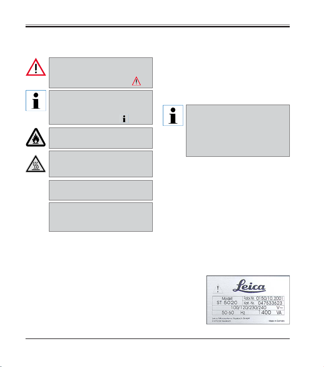
1.4 Instrument type
All information provided in this manual applies
only to the instrument type indicated on the title
page.
A name plate
indicating the
instrument se-
rial number is
attached to the
back of the in-
strument.
1.1 Symbols used in this manual
Warnings
appear in a grey box and are
marked by a warning triangle .
Notes,
i.e. important user information ap-
pear in a grey box and are marked
by an information symbol .
Flammable solvents and reagents
are marked with this symbol.
Instrument surfaces which become
hot during operation are marked
with this symbol.
Figures in brackets refer to item
nos. in drawings.
Function keys to be pressed on the
instrument touch screen are written
in bold-print capital letters.
(5)
ENTER
and their meaning
1.2 Designated use
The Stainer Leica ST5020 is an automated stain-
er for the preparation of histological and cyto-
logical routine stainings.
It is designed for use in pathology laboratories,
and only for performing the following tasks:
• Staining of thin sections of tissue specimens
or of cytological samples, attached to micro-
scope slides
• The instrument may be operated only ac-
cording to the instructions contained in this
manual.
Any other use of the instrument
is considered improper!
To prevent damages to the
instrument and specimens, only
those accessories and spare parts
which have been authorized by
Leica may be installed or used
with the instrument.
7
Leica ST5020
2. Safety
Make sure to comply with the safety instructions and warnings in this chapter.
Make sure to read these instructions, even if you are already familiar with the operation
and use of other Leica products.
2.2 Warnings
The safety devices installed in this instrument by the manufacturer only constitute the basis for
accident prevention. Primarily responsible for accident-free operation is above all the institu-
tion which owns the instrument and, in addition, the designated personnel who operates, ser-
vices or repairs the instrument.
To ensure trouble-free operation of the instrument, make sure to comply with the following in-
structions and warnings.
Material safety data sheets can be obtained from the supplier of the chemicals.
They are also available on the Internet:
http://www.msdsonline.com
The protective devices on both instrument and accessories may neither be removed nor
modified. Only authorized and qualified service personnel may repair the instrument and
access the instrument’s internal components.
This instrument has been built and tested in ac-
cordance with the following safety regulations
on electrical measuring, control, regulating and
laboratory devices.
In order to maintain this condition and to ensure
safe operation, the operator must observe the
instructions and warnings contained in this In-
structions for Use.
For current information about
applicable standards, please refer
to the CE declaration of conformity
on our Internet site:
www.LeicaBiosystems.com
2.1 Safety instructions
This Instructions for Use includes important in-
formation related to the operating safety and
maintenance of the instrument and it is an im-
portant part of the product.
If additional requirements on acci-
dent prevention and environmental
protection exist in the country of op-
eration, this Instructions for Use must
be supplemented by appropriate in-
structions to ensure compliance with
such requirements.

8
Instructions for Use, V1.9, RevD - 12/2012
Warnings - Markings on the instrument itself
Markings on the instrument showing the warning triangle indicate that the correct
Instructions for Use (as defined in this manual) must be followed when operating or re-
placing the item marked.
Failure to adhere to these instructions may result in an accident, personal injury, damage
to the instrument or accessory equipment.
Some instrument surfaces, which become hot during operation are marked with
this warning label. Touching these surfaces may cause burns.
Warnings -handling reagents
Be careful when handling solvents!
Always wear rubber gloves and safety goggles when handling the chemicals used in this
instrument.
Reagents used for tissue infiltration can be both toxic and/or flammable.
Dispose of waste solvents with care according to local regulations and the waste man-
agement policy of the company or institution.
Warnings - Transport and Installation
The instrument may only be transported in an upright position.
Four people are needed to lift / carry the instrument.
Install the instrument on an even laboratory bench which must be absolutely level.
Do not expose the instrument to direct sunlight (windows).
The instrument MUST be connected to an earthed mains power outlet socket. The instru-
ment must not be connected to an extension cord without protective earth conductor.
The instrument will automatically adjust to the required voltage and frequency at the
place of installation.
If new ovens are installed, they must be adjusted to the voltage and frequency required at
the installation site.
The instrument must be set up in a well ventilated area, free from any ignition sources.
The chemicals to be used in the Leica ST5020 are both flammable and noxious. Do not op-
erate the instrument in rooms with explosion hazard.
If there is a significant difference in temperature between the warehousing and the in-
stallation site of the instrument and if at the same time there is a high air humidity level,
condensation water may form. In this case, a waiting period of at least two hours must be
observed before the instrument is switched on. Failure to adhere to this waiting period
may result in damage to the instrument.
2. Safety
9
Leica ST5020
Warnings - Operating the instrument
The Leica ST5020 may only be operated by trained laboratory personnel, according to its
designated use and per the present Instructions for Use.
In case of emergency switch off mains and unplug the power chord.
While working with reagents (filling / emptying the reagent stations, working on the in-
strument while the lid/s is/are open) appropriate protective gear (lab coat, gloves, safety
goggles) must be worn.
Make sure to operate the instrument either with the activated carbon filter or with the ex-
haust air hose. Even when the instrument is operated according to its designated use,
hazardous solvent fumes develop, which are damaging to the operator’s health and do
also pose a risk of fire!
Risk of fire, when working with an open flame (Bunsen burner) immediately next to the
instrument (solvent fumes)! - Therefore, keep a safety distance of 2 meters!
If a staining program is to be interrupted for an extended period of time, do not leave any
slide racks in the tap water stations, in order to prevent them from drying out.
2. Safety
Warnings - Cleaning and maintenance
Prior to each maintenance and/or cleaning, switch the instrument off and disconnect
mains power. Do not clean the instrument with solvents containing acetone or xylene. No
liquid may be spilled into the internal components of the instrument - neither during op-
eration nor during cleaning.
When working with cleaning detergents, comply with all safety instructions by the manu-
facturer of the product and the laboratory management policy.
Wash the tap water and reagent stations in the dishwasher at a temperature of max.
+65°C (149 °F). Use a standard detergent for laboratory dishwashers.
At any rate avoid washing the stations at higher temperatures, as the stations may be-
come deformed!
Spilled solvents (reagents) have to be wiped away immediately! - In case of long-term ex-
posure, the lid surfaces are only conditionally resistant to solvents!
To clean the lids, control panel and housing, use mild household detergents; - see safety
instruction above for non-appropriate ingredients!
Caution with sequences which involve an oven at the initial step.
In this case the loading unit, out of which the specimen holder is removed via the
transport arm, must NOT be filled with an inflammable reagent (e.g. xylene).
As the oven temperature is up to 80°C (176 °F), the reagent may ignite and cause damage
to the device and to the samples.
For the same reason, steps conducted INSIDE an oven must never be carried out from a
reagent station with inflammable reagents.
10
Instructions for Use, V1.9, RevD - 12/2012
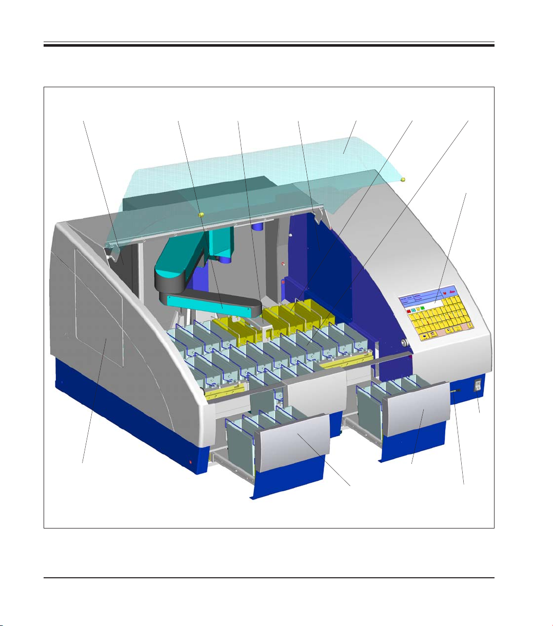
3.1 Overview - Instrument components
3. Instrument components and specifications
Fig. 1
Activated
carbon filter
Transfer arm Lid
Wash
stations
Single (Double)
carrier
Reagent
container
Color touch
screen
Mains
switch
Slot for
PCMCIA
card
Load
drawer
Exit
drawer
Oven
modules
Transfer to
Coverslipper
Leica CV5030
(optional)
11
Leica ST5020
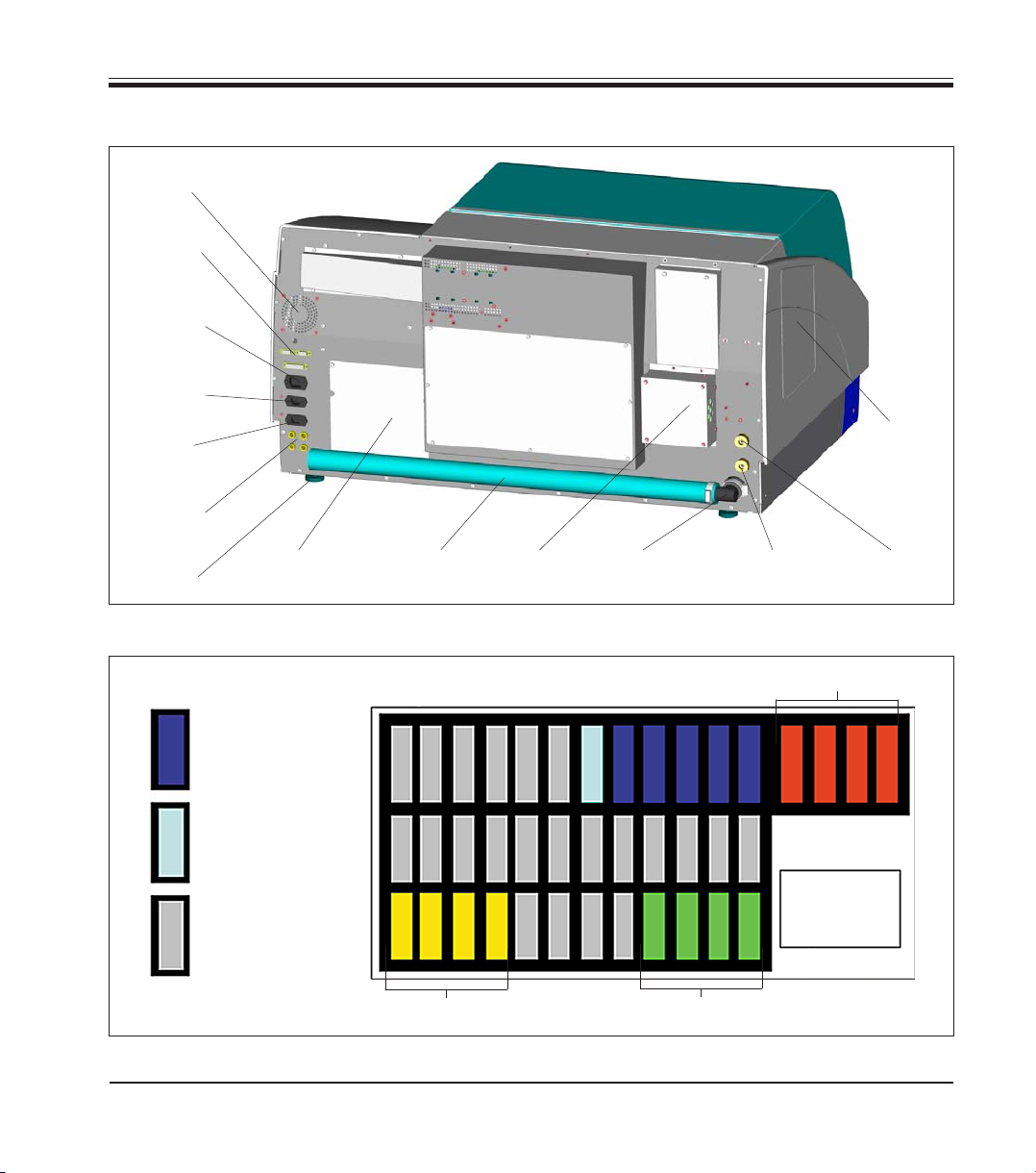
3. Instrument components and specifications
Rear of instrument
Fig. 3
Fig. 2
Wash
stations
Wash
station
DI-water
Reagent
container
Color touch
screen
Exit drawer
Load drawer
Cover for
Oven-Modules
Secondary
fuses
Oven-Modules
Transfer to
Coverslipper
(optional)
Drain
hose
Exhaust
air duct
Drain
outlet
Water inlet
Stations 8-12
DI-Water inlet
Station 7
Fan
electronic
Data
connections
adjustable
foot
Container map
Mains
Power supply
inlet
Power supply
outlet
Power supply
inlet
(electronic)
12 3 456 7 89101112 37383940
181716151413 2322212019 24
25
29282726 33323130 363534
12
Instructions for Use, V1.9, RevD - 12/2012
3.2 Instrument specifications
• High specimen throughput (at maximum 12 racks simultaneously)
• Simultaneously processing of multiple different programs
• Color TFT-Touch screen
• Graphical and intelligent user Interface
• Context-sensitive On-line Help
• Graphical process representation on color screen.
• Reagent Management System.
• Multilingual.
• Maximum of 40 stations.
• Load drawer with max. 4 stations.
• Exit drawer with max. 4 stations.
• Maximum of 6 wash stations, 2 different water sources possible.
(individually valve-controlled)
• CodeRack
TM
Programmable Slide Rack for automatic rack start.
• Overflow Protector (sensor) in stainless steel sink.
• Integrated fume control system with external hose/filter.
Optional Accessories
• Oven modules max. +65°C and up to 4 stations.
• Heated reagent stations (35 - 70°C max.), max. 2,
• Special Stain Kit.
(modified container with reduced reagent volume and racks).
• System upgrade for Coverslipper integration.
(automated staining and coverslipping without operator interaction).
• Air evacuation hose.
• Slide rack (plastic).
• Adapter for racks from other manufacturers.
3. Instrument components and specifications
To prevent damages to the instrument and specimens, only those accessories and
spare parts which have been authorized by Leica may be installed or used with the
instrument.

13
Leica ST5020
3.3 Standard delivery - packing list
The Leica ST5020 standard delivery consists of the following items:
1 Leica ST5020 basic instrument
31 Reagent vessels, assy. (with handles and lids) 14 0475 33659
5 Wash vessels, assy. 14 0475 33660
2 Activated carbon filter 14 0474 32273
1 Set of power cords:
1 Power cord "D" 14 0411 13558
1 Power cord "UK" ST-BU F-5A 14 0411 27822
1 Power cord "USA-C-J" 14 0411 13559
1 Accessory-Kit consisting off: 14 0475 39617
1 Jumper cable - mains 14 0411 34604
3 Reagent vessels, assy. (with handles and lids) 14 0475 33659
1 Set of clips, red, pack of 5 14 0475 33637
1 Set of clips, yellow, pack of 5 14 0475 33633
1 Set of clips, white, pack of 5 14 0475 33632
1 Set of clips, light blue, pack of 5 14 0475 33634
1 Set of slide racks 30, plastic, pack of 5 14 0475 33750
1 Waste water hose, 4 m length 14 0475 35748
1 Hose clamp for waste water hose 14 0422 31972
1 Tap water inlet hose, 2,50 m length, assy. with 3/4” connection for water tap 14 0475 32325
1 ‘V’ strainer 3/4”-40/22 A6 (strainer for inlet hose) 14 0456 36101
1 Threaded nippel 14 0474 33063
2 Gaskets for tap water inlet hose 14 0300 00132
1 Box level 14 0475 37629
1 Special O-ring grease for valves and O-rings (OHA), 25 ml 14 0336 36657
1 PCMCIA Flash Card, with adapter 14 0475 42526
1 Tool set:
1 Screw driver 5.5 x 200 14 0170 10702
1 Allen key, size 3.0, with handle 14 0194 04764
1 Allen key, size 4.0, with handle 14 0194 04782
1 Allen key, size 6.0 14 0194 03959
1 Ring-head wrench, size 13 14 0330 37628
1 Single-head wrench, size 17 14 0330 19641
1 Set of replacement fuses:
4 x T 2.0 A 14 6943 02001
2 x T 2.5 A 14 6943 02501
2 x T 4.0 A 14 6943 04001
1 Instructions for Use Leica ST5020 Multistainer 14 0475 80101
3. Instrument components and specifications

14
Instructions for Use, V1.9, RevD - 12/2012
3.4 Technical Data
General
Approvals: The instrument-specific marks are located next to
the identification label
Nominal voltage: 100 V - 120 V +/- 10%
230 V - 240 V +/- 10%
Nominal frequency: 50 to 60 Hz
Maximum power draw: 1400 VA
IEC 1010 classifications: Protective class 1
Pollution degree 2
Overvoltage installation category II:
• 800 V impulse (120 V systems)
• 1500 V impulse (240 V systems)
Remote alarm relay: 24 V AC/DC, maximum 2 A
Connection:
potential-free contact
(can be operated both as normally open and as
normally closed circuit)
Primary fuses: Fa. Schurter: type FST, mains power inlet 2 x T 8 A
Secondary fuses: Melting fuse, Ø 6.3x32 mm
Type: Schurter FST
F1: T 2.0 A
F2: T 2.0 A
F3: T 2.5 A
F4: T 4.0 A
Operating temperature range: 15 °C to 40 °C
Relative humidity: 10% to 80%, non-condensing
3. Instrument components and specifications

15
Leica ST5020
Capacity data
Specimen slide throughput: depending on the program-structure
Loading capacity: max.12 slide racks (with 12 different Programs)
Slide rack capacity: 30 specimen slides
Total number of stations: 40 (36 + 4 Oven)
Total number of reagent stations: max. 34
Reagent container volume: 450 ml
Number of wash stations: max. 5 and 1 DI-water (optional)
Oven (optional): 2 or 4
Oven chamber temperature: 40 °C to 70 °C or 104 °F to 158 °F
Incubation time setting: 0 sec. up to 23 hours, 59 min., 59 sec.
Load/unload stations: max. each 4, min. each 1
Permanent memory capacity: max. 50 Programs, up to 40 program steps each
Integration: connection to Leica CV5030 Coverslipper (optional)
Dimensions and weight
Basic instrument (W x D x H), in mm: 1060 x 750 x 540
Dry weight, unpacked: ca. 90 kg
Weight, packed: ca. 110 kg
3. Instrument components and specifications
16
Instructions for Use, V1.9, RevD - 12/2012
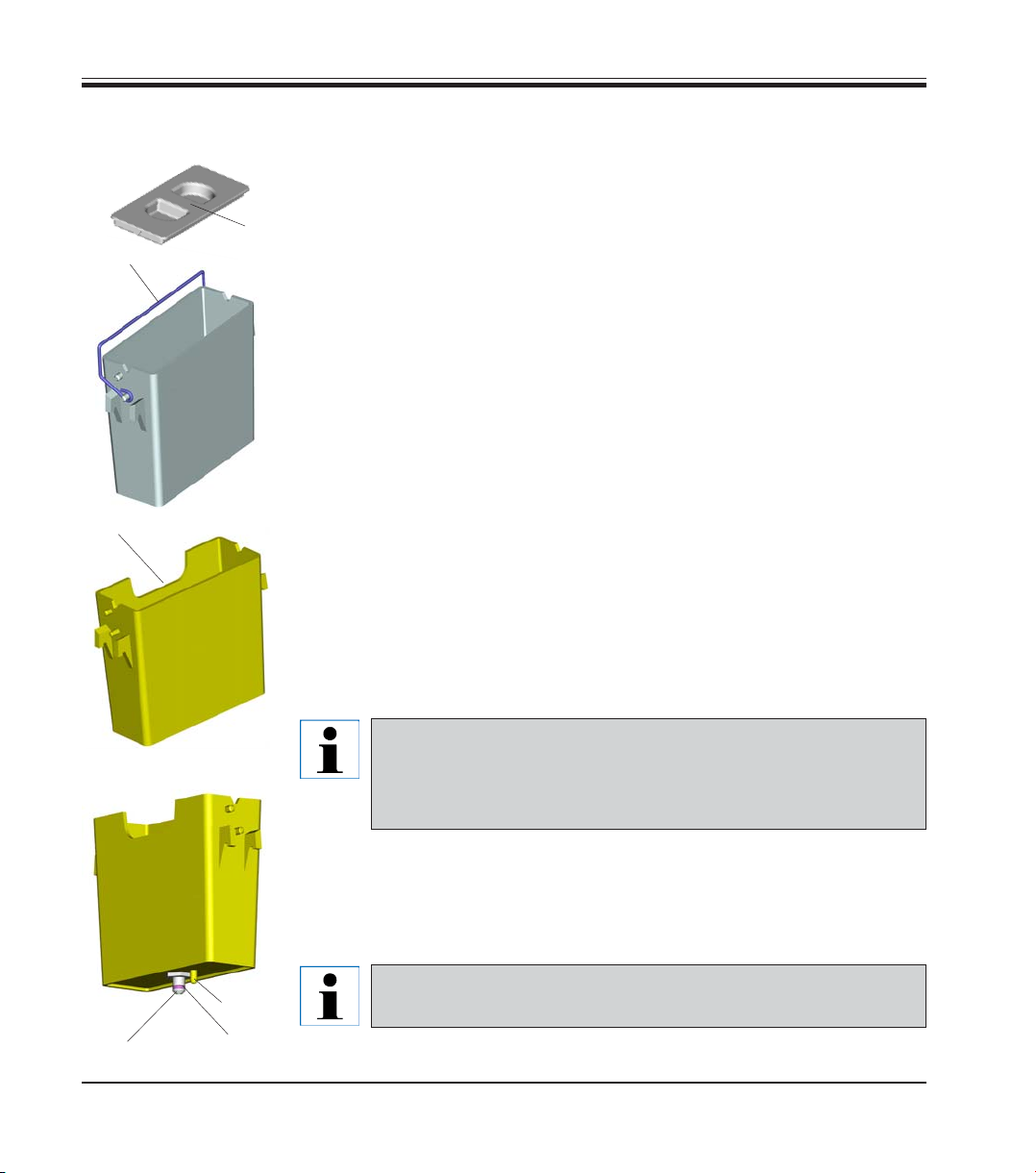
3.5 Container system
Reagent container
The Reagent containers can be individually removed for filling.
For use, fill the reagent containers to the line marked on the inside
(approx. 450 ml capacity) and place into position in the instrument consis-
tent with the programs you wish to run.
Ensure that the reagent containers are correctly seated and that the
handles (1) are over to the side and will not obstruct slide rack movement.
Lids (6) are provided to reduce evaporation while the reagent containers
are not in use.
The Load and Exit drawer containers (E25 and L36) can be filled with a re-
agent if desired.
However, the instrument will not control the immersion time in these sta-
tions.
Wash stations
The wash system consists of five (optional six) wash stations each ca-
pable of holding one slide rack. Water enters the wash station through a
connection piece (2) in the base and exits from the overflow lip (3) at the
top left hand edge.
Wash stations have a locating pin (4) and can only be inserted
one way. Take care when fitting or removing wash stations as
excessive force may damage the O-ring (5) used as a seal.
Lubricate the O-ring seal before fitting a wash station.
To use the wash system, slowly turn the laboratory tap on fully. The flow
control valve in the Leica ST5020 will limit the total water flow in the wash
stations to 1.6 liters/minute/station.
If the water flow drops below this level for any reason the
wash period specified in the program may have to be extended.
3. Instrument components and specifications
3
1
2
5
4
6
Fig. 4

17
Leica ST5020
4. Setting up the instrument
4.1 Installation site requirements
• Stable, exactly horizontal laboratory bench
with even surface of a minimum width of 1.60
m and minimum depth of 0.80 m.
• Tap water supply located a maximum of 2.50
m and waste water drain pipe a maximum of
2.00 m away from the corresponding in-/out-
lets at the rear panel of the instrument.
• If the instrument is to be operated with air
evacuation hose, a fume cupboard at a dis-
tance of maximum 3.50 m from the instru-
ment is required.
Alternative: operation with activated carbon
filter.
• Sufficient space (ca. 0.90 m) above the labo-
ratory bench for opening / closing the instru-
ment lid without any problem.
• Virtually vibration-free floor.
• Stable ambient temperature between +10 °C
and +40 °C.
• Relative air humidity of maximum 80%, non-
condensing.
• Do not place near instruments which might
be sources of vibration.
The chemicals to be used in the
Leica ST5020 are both flammable
and noxious. The instrument must
be set up in a well ventilated area,
free from any ignition sources.
Do not operate the instrument in
rooms with explosion hazard.
• To lift, grip the instrument by the carrying
handles (1, Fig. 5).
Four people are required to lift and/
or carry the instrument, as the in-
strument weighs a total of approx.
95 kg.
• Place the instrument onto the bench.
• Unscrew the carrying handles (remove
screws (2) with Allen key, size 6.0) and store
away.
• Pull off plastic cover.
• Check whether all accessories have been
delivered as per your order.
4.2 Installing the instrument
Fig. 5
1
2
18
Instructions for Use, V1.9, RevD - 12/2012
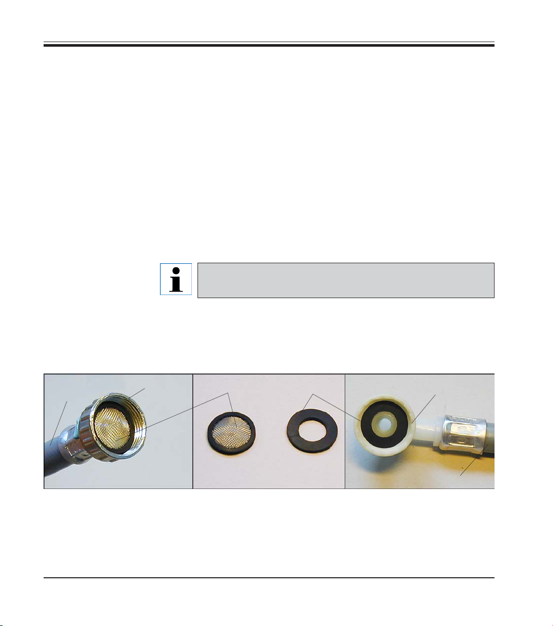
4.3 Tap water supply connection
Fig. 6
3
Connecting the tap water inlet hose
• Unpack the tap water inlet hose - mind the two gaskets (4).
4
5
6
• Insert one gasket (4) into threaded fitting (6). Store away the remaining
gasket(s).
• Insert strainer (3) into union nut (5) (see
Fig. 6) which is screwed onto
the water tap. Do not insert any further gaskets, as the strainer acts
also as a seal.
7
7
4. Setting up the instrument
Water filter
In addition to the filter sieve supplied (item 3 in
Fig. 6) Leica recommends
installing a sediment filter between the water extraction outlet and
ST5020, to guarantee that the instrument is only operated with clean wa-
ter.
This sediment filter should have the following properties:
Filter fineness: 25 μm
Rate of flow: approx. 10 l/min (with 5 wash stations)
Pressure constancy: 10 bar
Connection to the filter output: 1/2“ external thread
This filter insert must be checked and cleaned regularly.
If the filter insert is very dirty it must be replaced.
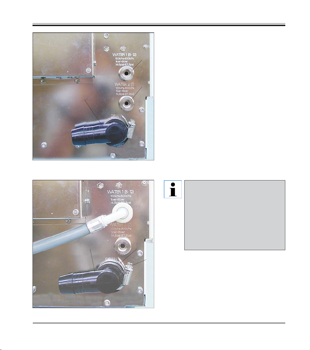
19
Leica ST5020
Fig. 8
Instrument rear panel
water in-/outlets
4. Setting up the instrument
10
11
7
12
Fig. 7
8
9
10
Instrument rear panel
- tap water inlets
• Screw tap water inlet hose (7 in Fig. 8) for
tap water stations 8 - 12 onto water tap and
insert the other end into inlet (8 in Fig. 7) .
• If station no. 7 (Fig. 3) will also be used as a
tap water station, connect a second tap
water inlet hose (optional accessory) to inlet
(9).
Inlet (9) only provides water (or any
other medium supplied via a sepa-
rate connection) to station no. 7. To
use station 7 as a water station, a
wash vessel must be inserted and
station 7 must be defined as a ‘tap
water’ or ‘fully-de-ionized water’
station (DI water station) in ‘stations
options’. (see also Chapter 5.5.3)
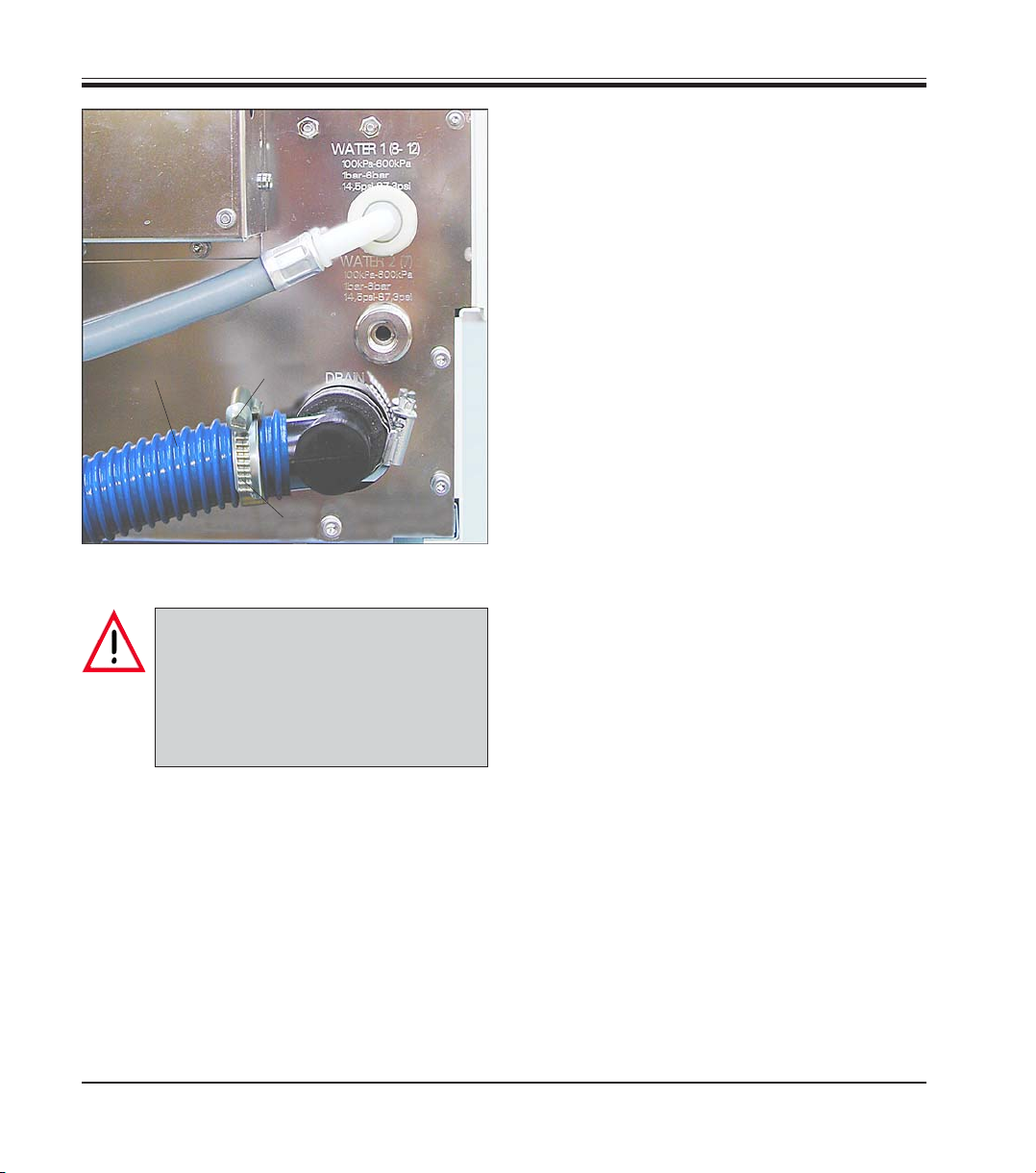
20
Instructions for Use, V1.9, RevD - 12/2012
Connecting the waste water hose
• Outlet connection piece (10) can be turned
to point into different directions, depending
on whether the drain water pipe is located to
the left or to the right of the instrument.
• To adjust the connection piece, loosen
screw (11) of hose clamp (12) sufficiently so
that the connection piece (10) can be turned.
Adjust the connection piece as desired (al-
ways with the opening pointing slightly
downwards) and retighten screw (11).
• Turn screw (15) to the left (use screwdriver)
until hose clamp (14) opens wide enough to
be slid over waste water hose (13).
• Fit waste water hose (13) onto outlet con-
nection piece (10) and position hose clamp
(14) as shown in
Fig. 9.
• Turn screw (15) to the right until hose (13) is
secured tightly on connection piece (10) by
hose clamp (12).
• Insert waste water hose (13) into drain pipe
and secure in position.
Fig. 9
7
13
14
15
Important!
When installing the drain hose al-
ways make sure there is a sufficient
descending gradient from the outlet
(connection piece (10)) on the instru-
ment to the drain pipe!
4. Setting up the instrument

21
Leica ST5020
4.4 Installing the oven (optional)
The following parts must be in-
cluded:
15 - Oven module
16 - Paraffin collecting tray
17 - Cover
18 - Screws
19 - Washers
20 - Screwdriver
21 - Allen key, size 2.5
22 - Allen key, size 4.0
• Take the oven kit out of the box and verify
whether it is complete.
15
16
17
18
19
22
21
20
Fig. 10
Insert paraffin collecting tray
into corresponding opening in
oven module (possible only in
one direction, as shown here).
• Check the voltage selector setting and ad-
just if necessary.
Important!
The voltage selector switch must be
set to the same mains voltage as the
instrument.
To adjust the voltage selector setting, insert
screw driver (20) into gap (23) and turn care-
fully until the white point above the correct
voltage indication is located underneath the
white triangle.
115 means: Instrument voltage 100 -120 V.
230 means: Instrument voltage 230 - 240 V.
Fig. 11
Rear panel - oven
Voltage setting
100 - 120 V
Voltage setting
230 - 240 V
24
25
23
4. Setting up the instrument

22
Instructions for Use, V1.9, RevD - 12/2012
• Cover panel (26) must be removed from the
right inner wall of the instrument, so that the
transfer arm can access the oven stations.
• To do so, remove six screws (27) (Allen key,
size 2.5) and remove cover panel (26).
• Store screws and cover panel in safe place
for further use.
Important!
Prior to taking any further installa-
tion steps, switch the instrument off
and unplug from mains.
• Remove cover panel (28) located to the right
of the electrical connections at the rear wall
of the instrument.
• To remove panel (28), only remove screws
(29).
Do not loosen the two screws (30)!
• Once the oven is installed, attach cover
panel (part of oven kit delivery) (17
in Fig. 10)
with four screws (29) in such a way that the
voltage selected is visible from the outside.
Fig. 12
Fig. 13
26
27
27
28
29
29
29
29
30
4. Setting up the instrument
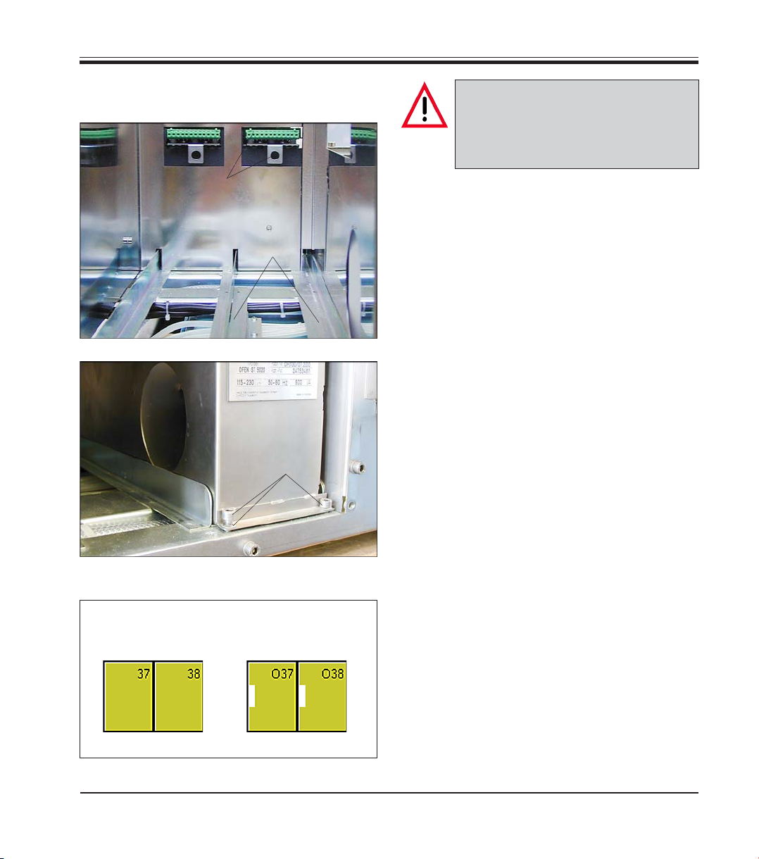
23
Leica ST5020
Important!
If only one oven is installed, it must
be located on the right side (seen
from the rear of the instrument).
• Place oven on rails (32) and insert.
• Keep pushing until the connection pieces of
the oven (positioning pin (24), connector
strip (25), see
Fig. 11) lock into the corre-
sponding connections (31) in the instrument.
Installing the oven
(continued)
• Plug the instrument back into mains and
switch on. The oven modules are detected
automatically and are displayed accordingly
in ‘instrument status’.
• Go to ‘stations options’ and set the desired
oven temperature.
(See
chapter 5.5.3, page 56 for further de-
tails).
• Next, use the two screws (18) and washers
(19) to secure the oven (15) in the bores pro-
vided in the instrument for that purpose.
• If a second oven has been ordered, install it
the same way as the first.
• Fasten cover (item 17, Fig. 10) so that the
voltage range selected for the oven (15) is
the same as the engraved voltage range.
Fig. 14
Fig. 15
15
31
32
18, 19
Indication with
ovens installed
Indication prior to
installing the ovens
INSTRUMENT STATUS
Fig. 16
4. Setting up the instrument

24
Instructions for Use, V1.9, RevD - 12/2012
4.5 Connecting the air evacuation hose
(optional)
• Fasten connection piece (64) with two
screws (63) into tap holes (66) in fan housing
(68).
• Turn clamping screw (67) to the left (use
screw driver (60) until hose clamp (62) is
loosened far enough so that it can be slipped
over the air evacuation hose.
60
65
64
62
63
61
Fig. 17
• Place air evacuation hose (65) together with
hose clamp (62) onto connection piece (64)
(see Fig. 18, right).
• Tighten screw (67) of hose clamp (62) (turn
to the right) to secure the hose.
68
66
66
Fig. 18
64
63
67
62
65
4. Setting up the instrument
If the instrument is operated without activated
carbon filter, the air evacuation hose must be
installed instead.
The air evacuation hose is attached to fan hou-
sing (68) located at the rear left of the instru-
ment. Unpack the components supplied and
check for completeness. The package must
contain the following items:
60 - Screw driver
61 - Allen key, size 2.5
62 - Hose clamp
63 - Allen screw with washer
64 - Hose connection piece with seal
65 - Air evacuation hose

25
Leica ST5020
Once the activated carbon fil-
ter is inserted, push lever (35)
downwards to properly se-
cure the filter in the filter
housing.
4.6 Inserting the activated carbon filter
Make sure to insert the filter
with the correct side pointing
upwards: the three arrows on
the label (51) located at the
right of the filter must point to
front.
Important for trouble-free
operation:
The sealing profiles (33) must
fit against the rear wall of the
filter housing (34).
Fig. 19
33
34
35
Fig. 18
Filter - inserted
51
4. Setting up the instrument
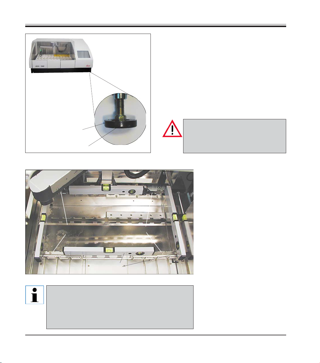
4.7 Leveling the instrument
• Once all accessories are installed (don’t forget the rear panel!), move
the instrument to its final position.
• Prior to leveling the instrument, check whether the bench surface of
the laboratory bench where the instrument will be installed is flat and
exactly horizontal.
• Otherwise, use the box level (standard delivery) to determine the high-
est point of the bench. Next, the instrument foot located at the highest
point of the bench must be screwed in almost completely (
see Fig. 21).
- Then level the instrument adjusting each foot as needed.
26
Instructions for Use, V1.9, RevD - 12/2012
To do so, proceed as follows:
• Remove all vessels located in stations 1 - 24
so that the vessel holder frames can be used
to support the box level for measuring pur-
poses.
• All four instrument feet (37) are height-ad-
justable.
To adjust, place single head wrench, size 13
(standard delivery) onto hexagon bolt (36)
and adjust each foot as needed.
Make sure, all four instrument feet
are firmly set on the bench surface
once the instrument adjustment has
been completed.
36
37
Adjustable
instrument feet
Fig. 21
Bring the instrument to
an exact horizontal posi-
tion by screwing the ad-
justable feet in / out as
needed.
• For leveling, position box
level (38) alternately in posi-
tions (A and B) - see Fig. 22
on the vessel holder frame.
• Screw the instrument feet in-
ward / outward as needed,
gradually bringing the instru-
ment into a horizontal posi-
tion. Start with the instrument
foot located opposite the
highest point of the labora-
tory bench.
• Finally, place the box level in
positions (C und D) to double-
check whether the instru-
ment is in fact in a horizontal
position.
Fig. 22
Abb. 22 shows all four points (A to D) where the box
level must be positioned for leveling the instrument.
For leveling, the box level must be placed onto ves-
sel holder frame (39). - Do not place the box level
elsewhere.
38
39
39
A
B
C
D
4. Setting up the instrument
27
Leica ST5020
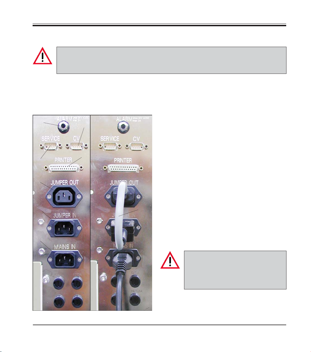
4.8 Electrical connection
The instrument MUST be connected to an earthed mains power outlet socket.
The instrument is supplied with a set of country-specific power cords.
Make sure to use the appropriate mains cable for the local voltage supply (wall outlet).
All electrical connections are located at the rear
of the instrument to the left (Fig. 23).
Power supply
• Connect mains cable to mains power supply
socket (42).
• Jumper cable (43) connects the mains power
supply output (44) to the electronics module
input (45).
Data connections
• Printer port (47)
A suitable printer (and cable) can be recom-
mended by your Leica distributor. If conform-
ance to electromagnetic interference stan-
dards is essential, a specially shielded printer
cable will be required.
• Serial port (48)
Access for technical service.
• Connection for Leica CV 5030 Cover slipper
(49).
All interfaces may be used only with
devices that have been tested in ac-
cordance with EN 60950 and which
satisfy the requirements for SELV cir-
cuits.
Other connections
• Socket for remote alarm system (50)
• Secondary fuses (46)
Fig. 23
Jumper cable / power cord
connected correctly
for mains power supply
50
Sockets for mains power
supply and data transfer.
Secondary fuses.
45
42
43
47
48
44
46
49
4. Setting up the instrument
Loading...