


 Loading...
20 |
30 |
40 |
50 |
RCS1100 Series |
|
||||
|
|
|
|
|
User Manual
Version 1.2
English

Remote Controlled Surveying
Congratulations on your purchase of an
RCS1100 system !
This manual contains important safety directions (refer to section "Safety directions") as well as instructions for setting up the instrument and operating it. Read carefully through the User Manual before you switch on the instrument.
2 |
RCS1100-1.2.0en |

Product identification
The instrument model and the serial number of your product are indicated on the type plate underneath.
Enter the model and serial number of your instrument in your user manual, and always refer to this information when you need to contact your agency or service workshop.
Model: |
|
Serial no.: |
Software version:
RCS1100-1.2.0en |
3 |
Product identification |

Symbols used in this Manual
The symbols used in this User Manual have the following meanings:
DANGER :
Indicates an imminently hazardous situation which, if not avoided, will result in death or serious injury.
WARNING:
Indicates a potentially hazardous situation or an unintended use which, if not avoided, could result in death or serious injury.
CAUTION:
Indicates a potentially hazardous situation or an unintended use which, if not avoided, may result in minor injury and/or in appreciable material, financial and environmental damage.
 Important paragraphs which must be adhered to in practice as they
  enable the product to be used in a technically correct and efficient manner.
Symbols used in this Manual |
4 |
RCS1100-1.2.0en |

View of chapters
Contents |
6 |
|
|
Introduction |
7 |
|
|
Preparation, setting up |
8 |
|
|
Description of the system |
15 |
|
|
Operation |
17 |
|
|
|
|
Care and Storage |
30 |
|
|
|
|
Safety directions |
32 |
|
|
|
|
Technical data |
41 |
|
|
|
|
Index |
43 |
|
|
RCS1100-1.2.0en |
5 |
View of chapters |

Contents
Introduction ....................................................... |
7 |
Preparation, Setting up..................................... |
8 |
Unpacking ................................................................... |
8 |
Fitting the RCS1100 to the reflector pole ...................... |
9 |
Installing the TCPS26 on the tripod of the instrument . 10 |
|
TPS1100/TPS1000 interface parameters ............. |
11 |
TPS1100/TPS1000 interface parameters ............. |
11 |
Switching on ............................................................. |
12 |
Trouble-shooting ....................................................... |
12 |
Packaging and transport ........................................... |
13 |
Batteries and chargers .............................................. |
13 |
Charging batteries ..................................................... |
14 |
Inserting and removing batteries ................................ |
14 |
Description of the system .............................. |
15 |
Description of the instrument ..................................... |
15 |
Software concept ...................................................... |
16 |
Operation ......................................................... |
17 |
Allocation of keys ...................................................... |
17 |
Working procedure .................................................... |
18 |
RCS Searching Window ...................................... |
19 |
Definition of a Working Area (WORKA) ............... |
19 |
Compass .............................................................. |
20 |
PowerSearch ....................................................... |
21 |
Hz / V ................................................................... |
21 |
Joystick ................................................................ |
22 |
Activate/Deactivate Work Area |
|
(WORK+/WORK-) ................................................ |
23 |
Last point stored .................................................. |
23 |
Switching the RCS mode ..................................... |
23 |
Lock interruption / Lock go................................... |
23 |
Complete display ................................................. |
24 |
Working with the TPS1000 series .............................. |
24 |
Local functions .......................................................... |
25 |
Power Off .................................................................. |
29 |
Care and Storage ............................................ |
30 |
Transport and Storage .............................................. |
30 |
Cleaning ................................................................... |
30 |
Battery charging ........................................................ |
31 |
Safety directions ............................................. |
32 |
Intended use of instrument ........................................ |
32 |
Permitted uses ..................................................... |
32 |
Prohibited uses .................................................... |
32 |
Limits of use .............................................................. |
33 |
Responsibilities ......................................................... |
33 |
Hazards in use .......................................................... |
34 |
Electromagnetic acceptability .................................... |
38 |
FCC statement (applicable in U.S.)............................ |
40 |
Technical data ................................................. |
41 |
Radio modem ........................................................... |
42 |
Index ................................................................. |
43 |
Contents |
6 |
RCS1100-1.2.0en |

Introduction
The control unit, the radio modem and the power supply are all contained in a compact, ergonomically-designed housing. The incorporated radio modem is used together with the TCPS26 radio modem as a basic station in the TPS1100.
Instruments in locations which are exposed, difficult to reach, or cramped, can be conveniently operated with the RCS1100 control unit.
Validity of the user manual |
6 |
|
This user manual is valid for all RCS1100 units having a built-in radio modem.
Exceptions relating to the RCS1100 without built-in radio modem are indicated. The present manuel describes the software version 1.22.
RCS1100 stands for Remote Control Surveying. The RCS1100 enables survey instruments of the TPS1100 and TPS1000 series to be remote controlled.
RCS1100-1.2.0en |
7 |
Preparation,SettingIntroductionup |
Preparation, Setting up
Unpacking
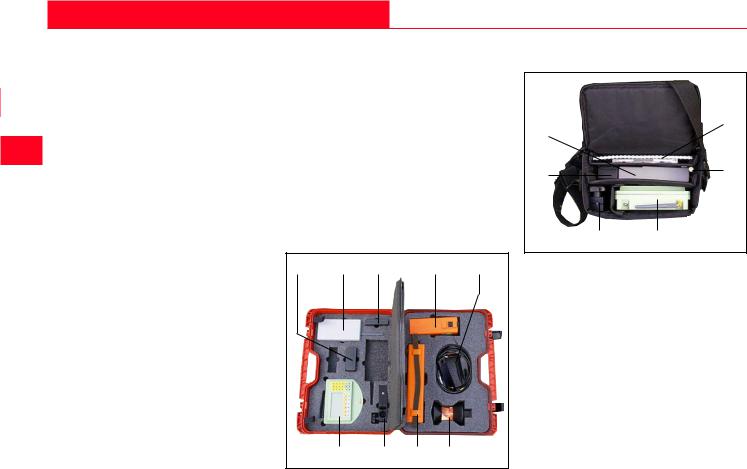
The RCS1100 is supplied complete with the User Manual and with a software diskette / CD in a padded nylon bag. The outfit also includes an adapter which enables the RCS1100 to be connected to a GLS11 reflector pole. The bag has space for a spare GEB111/121 battery and for a TCPS26 radio modem.
The complete equipment and the accessories for Remote Control Surveying can be reliably transported in the container 667 337 (option), in which all of the components are clearly laid out for rapid installation.
The entire equipment has been designed for rough field conditions but we nevertheless recommend that you use the bags and containers provided when you transport it over long distances. Protect cables, plugs, batteries and antennae against the weather.
9 |
8 |
7 |
6 |
5 |
1 2 3 4
10
8
7/9 |
11 |
21
1 RCS1100
2 Holder for reflector pole
3 Battery GEB71
4 360° Reflector
5 Y-cable, Antenna extension
6 Battery GEB70
7 Battery GEB111
8 TCPS26 radio modem
9 Battery GEB121
10User Manual, installation diskette
11Antenna
Preparation, Setting up |
8 |
RCS1100-1.2.0en |
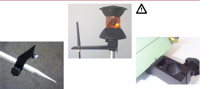
Fitting the RCS1100 to the reflector pole
Using the clamping screw provided, secure the reflector-pole adapter at the appropriate height on a GLS11 reflector pole. The adapter can remain on the reflector pole during transport.
WARNING: |
6 |
||
If the radio modem is |
|||
|
|||
switched on, do not carry the |
|
|
|
|
|
||
antenna closer than 15 cm to your |
|
|
|
body. |
|
|
|
|
|
|
|
|
|
|
|
Screw the antenna to the end of the antenna extension and connect the antenna extension to the reflector adapter.
Now connect the RCS1100 to the reflector-pole adapter by lining up the marks and tightening the screw. Connect the antenna extension to the RCS1100.
At short distances, or under favourable radio transmission conditions, you can leave out the antenna extension and connect the antenna directly to the RCS1100.
Connecting the RCS1100 (lining up the marks on housing and adapter)
The angle bracket and the position of the antenna socket together ensure that the antenna is vertical.
RCS1100-1.2.0en |
9 |
Preparation,Setting up |

Installing the TCPS26 on the tripod of the instrument
If the RCS1100 is secured in another manner, make sure that the antenna is vertical, otherwise the transmission range will be restricted.
2
1
1
2
|
Connect the following to the tripod of |
|
|
|
|
|
the instrument: The TCPS26 radio |
|
|
|
|
|
modem, the antenna extension with |
|
|
|
|
|
antenna, and the GEB70 or GEB71 |
|
|
|
|
|
external battery. Make sure that the |
|
3 |
|
|
|
|
|
|
||
|
antenna can transmit freely in the |
|
|
|
|
|
direction of work. The TCPS26 radio |
|
|
|
|
|
modem must be configured as the |
|
|
|
|
|
BASE modem. |
1 |
Antenna extension |
||
|
Using the Y-cable, connect the |
||||
|
2 TCPS26 radio modem |
||||
|
survey instrument, the battery and |
3 |
GEB70 external battery |
||
|
the TCPS26 radio modem. Connect |
|
|
|
|
Reflctor pole, completely set up |
the antenna extension to the |
|
|
|
|
|
TCPS26. |
|
|
|
|
Preparation, Setting up |
10 |
RCS1100-1.2.0en |
TPS1100/TPS1000 interface parameters
The interface parameters on the TPS1100 / TPS1000 must be inspected and if necessary adjusted to the those for the TCPS26, which were set in the factory to the following values:
19200 baud
8 data bits No parity
Setting the interface on the |
Setting the interface on the |
TPS1100: |
TPS1000: |
Switch on the RCS Mode on TPS1100/ TPS1000
Setting the interface on the |
6 |
|
TPS1100: |
||
|
||
MAIN\ Main menu |
MC |
|
|
||
MAIN\ Configuration |
MC |
|
MAIN\ Communication mode |
||
|
||
MAIN\ RCS mode |
|
|
Switches to Remote Control |
|
|
mode. |
|
|
Do you want to switch ? |
|
MAIN\ Main menu |
MC |
|
|
MAIN\ Configuration |
MC |
|
MAIN\ Communication mode
MAIN\ RCS parameters
Set the following values
19200 baud
8 data bits No parity
The remaining values are not relevant.
MAIN MENU: PROGRAMS |
MC |
|
CONF\ SYSTEM CONFIG.
CONF\ GSI-COMMUNICATION
Confirm with "YES".
MC Setting the interface on the TPS1000:
Set the following values:
19200 baud
8 data bits No parity
For details, refer to the TPS1000 Systems Handbook.
MAIN MENU: PROGRAMS |
MC |
|
|
EXTRA\ EXTRA FUNCTIONS |
MC |
|
EXTRA\ EXTRA FUNCTIONS
Switches to Remote Control mode.
Do you want to switch ?
Confirm with "YES".
RCS1100-1.2.0en |
11 |
Preparation,Setting up |

Switching on |
Trouble-shooting |
|
|
After all connections and settings have been inspected, the RCS1100 can be switched on. This automatically brings the TPS1100 into the RCS mode. After a few seconds, the display of the TPS1100 appears on the RCS1100.
Error |
Cause / remedy |
|
|
Case 1 - Green LED on TCPS26 does not shine: |
|
|
Inspect battery charge, and cables for TCPS26 |
|
No data transfer when |
Case 2 - Message "No signal" on RCS1100: |
|
Inspect battery charge in RCS1100 |
||
starting up (short |
||
or possible link numbers for RCS1100 and |
||
distance between |
||
TCPS26 are not the same. |
||
TCPS26 and RCS1100) |
||
|
Case 3 - Green LED shines and message appears |
|
|
on RCS1100: Set interface paarmeters correctly on |
|
|
TPS and TCPS26. |
|
|
Case 1 - Red LED on TCPS26 flashes: Inspect |
|
Data transfer possible, |
interface parameters. |
|
but transmission fault |
Case 2 - Red LED on TCPS26 does not flash: |
|
|
Connecting cable is defective |
|
Data transfer is very |
Disturbance from other transmitters in the 2.4 Ghz |
|
frequency band: Change link number in RSC1100 |
||
slow |
||
and TCPS26. |
||
|
||
|
|
|
|
Message "No signal" on RCS1100:Operation is at |
|
Interruption during data |
the limit of the range, or there is no visual |
|
communication between RCS1100 and TCPS26. |
||
transfer |
||
Establish visual communication, reduce distance, |
||
|
||
|
use antenna extension. |
|
|
|
Preparation, Setting up |
12 |
RCS1100-1.2.0en |
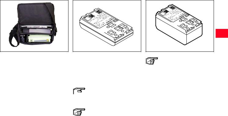
Packaging and transport |
Batteries and chargers |
|
|
Before packing up the RCS1100 and the TCPS26 in the bag, unscrew the antennae and remove the battery from the RCS1100. For maximum protection during transport, pack the units as shown in the diagram.
GEB111 |
T100Z72 |
|
Your Leica Geosystems instrument is operated with rechargable plug-in batteries. The GEB111 is the preferred battery for use with the RCS1100, but the GEB121 may also be used.
Only use batteries, charging
 sets and accessories recommended by Leica Geosystems.
In order to fully exhaust battery capacity it is
absolutely necessary with new batteries to carry out 3 to 5 complete charging/discharging cycles.
6
GEB121 |
1100z06 |
|
After first charging of batteries you can start
immediately with your job. As a result, the batteries will be discharged. Because the operating time of the battery can be very short until full capacity is reached it is recommended to have ready a second battery and the GKL122 battery charger. Using the charger, the battery can be charged/discharged several times before use.
RCS1100-1.2.0en |
13 |
Preparation,Setting up |
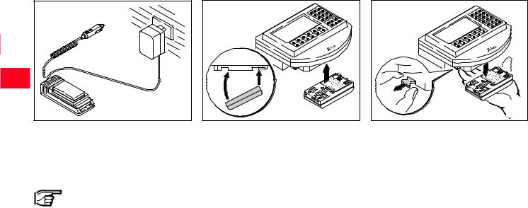
Charging batteries |
Inserting and removing batteries |
|
|
T100Z74 |
Tcs11z01 |
Tcs11z02 |
To charge the battery, use the GKL111 or GKL122 charger as described in the instructions provided with that charger.
The chargers are not intended for outdoor use.
Adhere to the safety directions.
The battery for the RCS1100 fits into a compartment on the underside of the instrument. Push it fully against the side opposite to the catch and then click it into position on the same side as the catch.
To remove the battery, hold it to prevent it from falling and pull out the lever of the catch by about 2mm.
Preparation, Setting up |
14 |
RCS1100-1.2.0en |
Loading...