


 Loading...
Leica TM6100A
User Manual
Version 1.0
English
Introduction |
|
TM6100A |
2 |
Introduction |
|
|
|
Purchase |
Congratulations on the purchase of a TM6100A instrument. |
|
|
|
This manual contains important safety directions as well as instructions for setting |
||
|
up the product and operating it. Refer to "6 Safety Directions" for further informa- |
||
|
tion. |
|
|
|
Read carefully through the User Manual before you switch on the product. |
|
|
Product |
The type and the serial number of your product are indicated on the type plate. |
|
|
identification |
Enter the type and serial number in your manual and always refer to this information |
||
|
when you need to contact your agency or Leica Geosystems authorized service work- |
||
|
shop. |
|
|
|
Type: |
_______________ |
|
|
Serial No.: |
_______________ |
|
Symbols
Trademarks
Validity of this manual
The symbols used in this manual have the following meanings:
Type |
Description |
|
|
Danger |
Indicates an imminently hazardous situation which, if not |
|
avoided, will result in death or serious injury. |
|
|
|
|
|
Warning |
Indicates a potentially hazardous situation or an unintended use |
|
which, if not avoided, could result in death or serious injury. |
|
|
|
|
|
Caution |
Indicates a potentially hazardous situation or an unintended use |
|
which, if not avoided, may result in minor or moderate injury |
|
|
|
and/or appreciable material, financial and environmental |
|
|
damage. |
|
|
|
|
|
Important paragraphs which must be adhered to in practice as |
|
|
they enable the product to be used in a technically correct and |
|
|
efficient manner. |
|
|
|
|
|
|
•CompactFlash and CF are trademarks of SanDisk Corporation
•Bluetooth is a registered trademark of Bluetooth SIG, Inc
All other trademarks are the property of their respective owners.
Description
General This manual applies to all TM6100A instruments.
Introduction |
TM6100A |
3 |

Introduction |
TM6100A |
4 |
|
|
|
Available documentation
Name |
Description and Format |
|
|
|
|
|
|
|
|
|
|||
|
|
|
|
|
|
|
|
|
|
|
|
|
|
User Manual |
All instructions required in order to operate the product |
|
|
|
|
|
|
to a basic level are contained in the User Manual. |
|
|
|||
|
Provides an overview of the product together with |
|
|
|||
|
technical data and safety directions. |
|
|
|||
|
|
|
|
|
|
|
Name |
Description and Format |
|
|
|
|
|
|
|
|
|
|||
|
|
|
|
|
|
|
|
|
|
|
|
|
|
System |
Describes the general working of the product in |
|
|
|
|
|
Field Manual |
standard use and specific onboard application |
|
|
|||
|
programs. Intended as a quick reference field guide. |
|
|
|||
|
|
|
|
|||
Technical |
Overall comprehensive guide to the product and |
|
|
|
|
|
Reference |
program functions. Included are detailed descriptions |
|
|
|||
Manual |
of special software/hardware settings and soft- |
|
|
|||
|
ware/hardware functions intended for technical |
|
|
|||
|
specialists. |
|
|
|||
|
|
|
|
|
|
|
Refer to the following resources for all TM6100A documentation and software
•the TPS6000 Product CD
•http://metrology.leica-geosystems.com/en/Downloads_6843.htm

Table of Contents
In this manual |
Chapter |
|
|
Page |
|
|
1 Description of the System |
8 |
|||
|
|
|
|
|
|
|
|
1.1 |
System Components |
8 |
|
|
|
1.2 |
System Concept |
11 |
|
|
|
|
1.2.1 |
Software Concept |
11 |
|
|
|
1.2.2 |
Data Storage and Data Conversion Concept |
13 |
|
|
|
1.2.3 |
Power Concept |
15 |
|
|
1.3 |
Container Contents |
16 |
|
|
|
1.4 |
Instrument Components |
17 |
|
|
2 |
User Interface |
|
20 |
|
|
|
|
|
|
|
|
|
2.1 |
Keyboard |
|
20 |
|
|
2.2 |
Hot Key Assignments |
24 |
|
|
|
2.3 |
Screen |
|
27 |
|
|
2.4 |
Operating Principles |
29 |
|
|
|
2.5 |
Icons |
|
35 |
|
3 |
Operation |
|
37 |
|
|
|
|
|
|
|
|
|
3.1 |
Instrument Setup |
37 |
|
|
|
3.2 |
Battery |
|
40 |
|
|
|
3.2.1 |
Operating Principles |
40 |
|
|
|
|
|
|
Table of Contents |
|
|
|
TM6100A |
5 |
Table of Contents |
|
|
TM6100A |
6 |
|
|
|
|
3.2.2 |
Instrument Battery |
41 |
|
|
3.3 |
Working with the CompactFlash Card |
43 |
|
|
|
3.4 |
Accessing Survey Application Program |
46 |
|
|
|
3.5 |
Built-in autocollimation device |
49 |
|
|
|
3.6 |
Connection to Application Computer |
51 |
|
|
|
3.7 |
Limitation of the horizontal and vertical movements |
55 |
|
4 |
Check & Adjust |
|
60 |
||
|
|
|
|
|
|
|
|
4.1 |
Overview |
|
60 |
|
|
4.2 |
Preparation |
63 |
|
|
|
4.3 |
Combined Adjustment (l, t, i and c) |
65 |
|
|
|
4.4 |
Tilting Axis Adjustment (a) |
69 |
|
|
|
4.5 |
Adjusting the Circular Level of the Instrument and Tribrach |
74 |
|
|
|
4.6 |
Adjusting the Circular Level of the Prism Pole |
76 |
|
|
|
4.7 |
Inspecting the Laser Plummet of the Instrument |
77 |
|
|
|
4.8 |
Servicing the Tripod |
79 |
|
|
|
4.9 |
Adjustment of the autocollimation reticule |
80 |
|
5 |
Care and Transport |
82 |
|||
|
|
|
|
|
|
|
|
5.1 |
Transport |
|
82 |
|
|
5.2 |
Storage |
|
84 |
|
|
5.3 |
Cleaning and Drying |
85 |
|
|
|
5.4 |
Maintenance |
87 |
|

6 |
Safety Directions |
88 |
||
|
6.1 |
General Introduction |
88 |
|
|
6.2 |
Intended Use |
89 |
|
|
6.3 |
Limits of Use |
91 |
|
|
6.4 |
Responsibilities |
92 |
|
|
6.5 |
Hazards of Use |
93 |
|
|
6.6 |
Laser Classification |
99 |
|
|
|
6.6.1 |
General |
99 |
|
|
6.6.2 |
Laser Plummet |
101 |
|
6.7 |
Electromagnetic Compatibility EMC |
104 |
|
|
6.8 |
FCC Statement, Applicable in U.S. |
107 |
|
7 |
Technical Data |
|
110 |
|
|
|
|
|
|
|
7.1 |
Angle Measurement |
110 |
|
|
7.2 |
Conformity to National Regulations |
111 |
|
|
|
7.2.1 |
Communication side cover with Bluetooth |
111 |
|
7.3 |
General Technical Data of the Instrument |
112 |
|
8 |
International Limited Warranty, |
|
||
|
Software License Agreement |
119 |
||
|
|
|
|
|
Table of Contents |
TM6100A |
7 |
Description of the System |
TM6100A |
1 - 8 |
|
1 |
Description of the System |
|
|
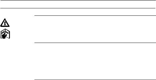
1.1System Components
Main components
TM6100A_001 |
TM6100A |
Component |
Description |
TM6100A |
• an instrument of highest accuracy for measuring, calculating |
|
and capturing data. |
|
• connected with LGO Tools to view, exchange and manage data. |
|
|
Application |
Third party metrology software with an interface to the TM6100A |
Software |
for acquisition, analysis, management and reporting of data. |
|
|
LGO Tools |
An office software consisting of a suite of standard and extended |
|
programs for the viewing, exchange and management of data. |
|
|

Terminology |
The following terms and abbreviations may be found in this manual: |
|
|
|
|
|
Term |
Description |
|
TPS |
Total Station Positioning System |
|
|
|
|
LGO Tools |
LEICA Geo Office Tools |
|
|
|
|
Motorised |
TM6100A instruments are fitted with internal motors, enabling |
|
|
automatic horizontal and vertical turning are referred to as |
|
|
Motorised. |
|
|
|
|
Communication |
Communication side cover with integrated Bluetooth is a compo- |
|
side cover |
nent with external devices, i.e. laptop with application software. |
|
|
|
|
|
|
Description of the System |
TM6100A |
1 - 9 |

Description of the System |
TM6100A |
1 - 10 |
|
Instrument models |
|
|
|
Model |
Description |
|
|
|
|
||
|
TM6100A |
Electronic theodolite, motorised, 0.5" accuracy. |
|
|
|
|
|
|
|
|
|
LEICA Geo Office |
• LGO Tools supports TM6100A instruments. It also supports all other Leica TPS |
||
Tools |
instruments. |
|
|
•LGO Tools is based on a graphical user interface with standard Windows® operating procedures.
•LGO Tools provides the following functionality:
Functionality |
Description |
Standard |
Includes data exchange between computer and instrument, data |
Functionality |
management including viewing and editing, reporting, creation |
|
and management of codelists, creation and use of format files for |
|
data conversion, uploading and deleting of system software and |
|
application programs. |
|
|
•Supported operating systems: Windows® XP, Windows® 2000.
•Refer to the online help of LGO Tools for additional information.
1.2System Concept
1.2.1Software Concept
Description Software type
TM6100A instruments support the following types of software.
Software type |
Description |
System |
This software comprises the central functions of the instrument. |
software |
It is also referred to as firmware. |
|
The programs Survey and Setup are integrated into the firmware |
|
and cannot be deleted. |
|
The English language is integrated into the firmware and cannot |
|
be deleted. |
|
|
Language |
Numerous languages are available for the TM6100A instruments. |
software |
This software is also referred to as system language. |
|
The system software enables a maximum of three languages |
|
which can be stored at any one time - the English language and |
|
two other languages. The English language is the default |
|
language and cannot be deleted. One language is chosen as the |
|
active language. |
|
|
Description of the System |
TM6100A |
1 - 11 |

Description of the System |
TM6100A |
1 - 12 |
|
|
|
|
|
|
Software type |
Description |
|
|
Application |
A suite of optional specific application programs are available for |
|
|
programs |
the instrument. |
|
|
|
Some of the programs are activated freely and require no license |
|
|
|
key and others require purchasing and are only activated with a |
|
|
|
license key. |
|
|
|
|
|
|
Third party appli- |
There are various third party applications available for the |
|
|
cation programs |
TM6100A, onboard or computer based software. Please contact |
|
|
|
your Leica Geosystems representative for details. |
|
|
|
|
|
|
Customised |
Customised software specific to user requirements can be devel- |
|
|
application |
oped using the GeoC++ development kit. Information on the |
|
|
programs |
GeoC++ development environment is available on request from a |
|
|
|
Leica Geosystems representative. |
|
|
|
|
|
|
|
|
|
Software upload All instrument software is stored in the System RAM of the instrument. The software can be uploaded onto the instrument using the following methods:
•Using LGO Tools the software is transferred via the serial interface to the CompactFlash card in the instrument, which is then stored to the System RAM.
•By connecting the CompactFlash card directly to the computer either via an internal card slot housing or an external OMNI drive, the software is transferred to the card, which is then stored to the System RAM.

1.2.2Data Storage and Data Conversion Concept
Description |
Data is stored within a job in a database on a memory device. This is either a |
|
|
CompactFlash card or an internal memory. |
|
|
|
|
Memory device |
CompactFlash card: |
A CompactFlash card housing is standard. A CompactFlash |
|
|
card can be inserted and removed. Available capacity: |
|
|
256 MB and 1 GB. |
|
|
Whilst other CompactFlash cards may be used, |
|
|
Leica recommends Leica CompactFlash cards |
|
|
and cannot be held responsible for data loss or |
|
|
any other error that may occur when using a |
|
|
non-Leica card. |
|
Internal memory: |
An internal memory is always fitted. It resides inside the |
|
|
instrument. Available capacity: 256 MB. |
Unplugging connecting cables or removing the CompactFlash card during the measurement may cause loss of data. Always return to TM6100A Main Menu before removing the CompactFlash card and switch off the instrument before removing cables.
Description of the System |
TM6100A |
1 - 13 |

Description of the System |
TM6100A |
1 - 14 |
|
Data conversion |
Export |
|
|
|
Data can be exported from a job in a wide range of ASCII formats. A standard set of |
||
|
Export Formats is delivered with the system. Customized export format can defined |
||
|
in Format Manager which is a PC tool in LEICA Geo Office Tools. Refer to the online |
||
|
help of LGO Tools for information on creating format files. |
|
|
|
Data can also be exported from a job in DXF or LandXML format. |
|
|
|
Import |
|
|
|
Data can be imported from ASCII, DXF, GSI8 or GSI16 format. |
|
|
|
|
||
Transfer raw data |
Raw data can be transferred between the database on the CompactFlash card or the |
||
to LGO Tools |
internal memory of the instrument and LGO Tools in two ways: |
|
|
•From the CompactFlash card or the internal memory directly via a serial interface to a project in LGO Tools on a PC.
•From the CompactFlash card using for example an OMNI drive as supplied by Leica Geosystems to a project in LGO Tools on a PC.
CompactFlash cards can be used directly in an OMNI drive as supported by Leica
Geosystems. Other PC card drives may require an adapter.

1.2.3Power Concept
General |
Use the Leica Geosystems batteries, chargers and accessories or accessories recom- |
|
|
mended by Leica Geosystems to ensure the correct functionality of the instrument. |
|
|
|
|
Power options |
Instrument |
|
|
Power for the instrument can be supplied either internally or externally. An external |
|
|
battery is connected to the instrument using a LEMO cable. |
|
|
Internal battery: |
One GEB241 battery fitted into the battery compartment. |
|
External battery: |
One GEB171 battery connected via cable |
Description of the System |
TM6100A |
1 - 15 |
Description of the System |
TM6100A |
1 - 16 |
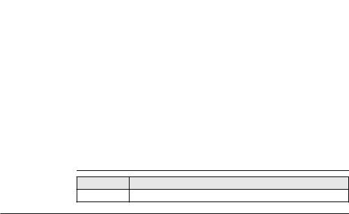
1.3
Container for instrument and delivered accessories
Container Contents
a |
f |
a) |
Protective cover for instrument and |
|
|
|
|
sunshade for objective lens |
|
|
g |
b) |
Container straps |
|
|
h |
c) |
Counterweight for diagonal eyepiece or |
|
|
|
zenith eyepiece - optional |
||
|
|
|
||
|
i |
d) |
Allen key |
|
|
j |
e) |
Spare stylus |
|
|
k |
f) |
Room for normal handle |
|
b |
g) |
Compact Flash card with cover |
||
l |
||||
c |
h) |
User manual |
||
m |
i) |
Autocollimation lamp AL51 - optional |
||
d |
|
j) |
CompactFlash card adapter with cover - |
|
n |
|
optional |
||
e |
k) |
Internal battery GEB241 - optional |
||
o |
l) |
Instrument with supplied stylus and |
||
TM6100A_039 |
||||
|
|
|
tribrach |
|
|
|
m) |
Data transfer cable GEV218 - optional |
|
|
|
n) |
Diagonal eyepiece GFZ3 or zenith |
|
|
|
|
eyepiece GOK6 (eyepiece for steep |
|
|
|
|
sighting) - optional |
|
|
|
o) |
Ball pen - optional |
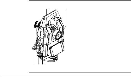
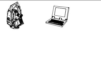
1.4Instrument Components
Instrument |
The instrument components of a TM6100A instrument are shown below. |
|
components |
a b |
c |
part 1 of 2 |
|
|
|
|
a) |
Carry handle |
|
|
|
b) |
Optical sight |
|
|
|
c) |
Panfocal telescope |
|
|
|
d) |
CompactFlash card compartment |
|
|
|
e) |
Horizontal drive |
|
|
|
f) |
User defined SmartKey |
|
|
|
g) |
Vertical drive |
|
d e f g |
h i |
h) |
Lemo connector |
|
i) |
Tribrach |
|||
TM6100A_002 |
|
Description of the System |
TM6100A |
1 - 17 |
Description of the System |
TM6100A |
1 - 18 |
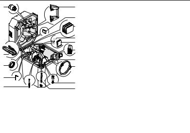
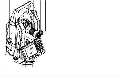
Instrument |
j |
k |
l m |
components |
|
|
|
part 2 of 2 |
|
|
|
n |
o p q r |
s |
TM6100A_003
j)Vertical drive
k)Focusing ring
l)Autocollimation device
m)Interchangeable eyepiece
n)Battery compartment
o)Stylus for touch screen
p)Screen
q)Circular level
r)Footscrew
s)Keyboard
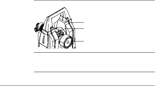
Internal target An internal target GUS29 may be factory fitted to the telescope of the TM6100A to facilitate the mutual accurate collimation of two theodolites. Depending on the measurement task, the internal target can be rotated into or out of position.
a b
c |
a) |
TM6100A |
|
b) |
Knob to rotate internal target GUS29 |
TM6100A_004 |
c) |
Panfocal telescope |
The internal target GUS29 is rotated into the visible positions when the marker line on the knob is perpendicular to the line of sight.
When the marker line on the knob is parallel to the line of sight, the internal target GUS29 is out of sight.
Description of the System |
TM6100A |
1 - 19 |

User Interface |
TM6100A |
20 |
2 |
User Interface |
|
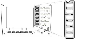
2.1Keyboard
Keyboard |
|
|
|
|
|
|
|
a |
|
|
|
|
|
|
ABC |
DEF |
GHI |
|
|
|
|
|
F12 |
7 |
8 |
9 |
|
|
|
|
|
|
JKL |
MNO |
b |
|
|
|
|
|
|
PQR |
||
|
|
|
|
|
F11 |
4 |
5 |
6 |
|
|
|
|
|
|
STU |
VWX |
YZ |
|
|
|
|
|
F10 |
1 |
2 |
3 |
|
|
|
|
|
F9 |
/$% |
_@& |
*?! |
|
|
|
|
|
0 |
. |
|
|
|
|
|
|
|
F8 |
|
|
c |
|
|
|
|
|
CE |
|
ESC |
|
|
|
|
|
|
F7 |
USER |
|
PROG |
|
|
|
|
|
|
|
OFF |
ON |
|
|
|
|
|
|
PgUp |
|
d |
|
|
|
|
|
|
|
|
|
|
|
|
|
|
SHIFT |
|
|
|
F1 |
F2 |
F3 |
F4 |
F5 |
F6 |
|
|
e |
PgDn
TM6100A_005
f g
a) |
Hot keys F7-F12 |
|
|
b) |
Alphanumeric keys |
e) |
Arrow keys |
c) |
CE, ESC, USER, PROG |
f) |
SHIFT |
d) |
ENTER |
g) |
Function keys F1-F6 |
Keys |
H Key |
Description |
|
Hot keys F7-F12 |
• Pre-defined keys to execute commands or access chosen |
|
|
screens. |
|
|
• The hot key F13, the user defined SmartKey, is located |
|
|
between the horizontal and vertical drive on the right |
|
|
hand side cover. |
|
|
|
|
Alphanumeric keys |
• To type letters and numbers. |
|
|
|
|
CE |
• Clears all entry at the beginning of user input. |
|
|
• Clears the last character during user input. |
|
|
|
|
ESC |
• Leaves the current menu or dialog without storing |
|
|
changes made. |
|
|
|
|
USER |
• Calls the user defined menu. |
|
|
|
|
PROG (ON) |
• If the instrument is off: to turn instrument on. |
|
|
• If the sensor is on: press at any time to select an applica- |
|
|
tion program. |
|
|
|
|
|
|
User Interface |
TM6100A |
21 |

User Interface |
TM6100A |
22 |
|
|
|
|
|
|
Key |
Description |
|
|
ENTER |
• Selects the highlighted line and leads to the next logical |
|
|
|
dialog/menu. |
|
|
|
• Starts the edit mode for edit fields. |
|
|
|
• Opens a list box. |
|
|
|
|
|
|
SHIFT |
• Changes between the first and the second level of func- |
|
|
|
tion keys. |
|
|
|
|
|
|
Arrow keys |
• Move the focus on the screen. |
|
|
|
|
|
|
Function keys F1-F6 |
• Correspond to the six softkeys that appear on the bottom |
|
|
|
of the screen when the screen is activated. |
|
|
|
|
|
|
|
|
|

Key combinations |
Keys |
Description |
|
||
|
PROG plus USER |
Turns instrument off. |
|
|
|
|
SHIFT F12 |
Calls STATUS Level & Laser Plummet. |
|
|
|
|
SHIFT F11 |
Calls CONFIGURE Lights, Display, Beeps, Text, Lights |
|
|
page. |
|
|
|
|
SHIFT USER |
Calls QUICK SET Change Settings to:. |
|
|
|
|
SHIFT |
Pages up. |
|
|
|
|
SHIFT |
Pages down. |
|
|
|
|
|
|
User Interface |
TM6100A |
23 |

User Interface |
TM6100A |
24 |
2.2Hot Key Assignments
General |
TM6100A instruments contain two standard configurations at delivery. Two more |
||
|
configurations are available on the Factory CD. |
|
|
|
|
|
|
|
|
|
|
|
Configuration Set |
Description |
Angle Unit |
|
TM6100A BT |
Standard configuration set for Bluetooth |
Degree |
|
|
connection |
|
|
|
|
|
|
TM6100A Cable |
Standard configuration set for Cable |
Degree |
|
|
connection |
|
|
|
|
|
|
|
|
|

Hot Keys |
All default configurations contain the following Hot Key & Shift Hot Key assignments: |
|
|
|
|
|
Key |
Description |
|
F7 |
Autocollimation lamp On/Off |
|
|
|
|
F8 |
Reticule illumination On/Off |
|
|
|
|
F9 |
Change face |
|
|
|
|
F10 |
Position Hz/V |
|
|
|
|
F11 |
TPS Correction (Environmental Parameters) |
|
|
|
|
F12 |
Check & Adjust |
|
|
|
|
F13 (Trigger Key) |
Rec (Take an angle measurement) |
|
|
|
|
Shift - F7 |
Compensator functions |
|
|
|
|
Shift - F8 |
Telescope accessories |
|
|
|
|
Shift - F9 |
Units & Formats |
|
|
|
|
Shift - F10 |
Battery & Memory Status |
|
|
|
|
Shift - F11 |
Lights & Display Settings |
|
|
|
|
Shift - F12 |
Electronic Level & Plummet |
|
|
|
|
|
|
User Interface |
TM6100A |
25 |
User Interface |
TM6100A |
26 |
Keyboard Overlay A self adhesive keyboard overlay is available for the default Hot Key assignments. The keyboard overlay can be affixed to the keyboard as shown below if required.
|
|
|
|
|
|
|
|
|
|
|
|
|
|
|
|
|
|
|
|
|
|
|
|
|
|
|
|
|
|
|
|
|
ABC |
|
DEF |
|
|
|
GHI |
|
|
|
|
|
F12 |
7 |
8 |
9 |
|
|
|
||||||||
|
|
JKL |
|
|
|
|
|
|
|
|
|
|
||
|
MNO |
|
|
PQR |
|
|
|
|||||||
F11 |
|
|
|
|
|
|
|
|
|
|
|
|
|
|
F10 |
|
|
|
|
|
|
|
|
|
|
|
|
|
|
|
|
|
|
|
|
|
|
|
|
|
|
|
|
|
F9 |
|
|
|
|
|
|
|
|
|
|
|
|
|
|
F8 |
|
|
CE |
|
|
|
|
|
|
|
|
|
|
|
|
|
ESC |
|
|
|
|||||||||
|
|
|
|
|
|
|||||||||
F7 
 USER
USER  PROG
PROG
OFF ON
PgUp
SHIFT
F1 |
F2 |
F3 |
F4 |
F5 |
F6 |
PgDn
TM6100A_006
2.3
Screen
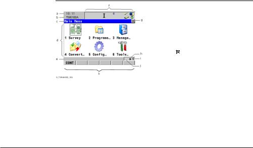
Elements of the screen
Screen
|
a) |
Time |
||
|
b) |
Caption |
||
|
c) |
Title |
||
|
d) |
Screen area |
||
|
e) |
Message line |
||
|
f) |
Icons |
||
|
g) |
ESC |
|
|
|
|
|||
|
|
|||
|
h) |
CAPS |
||
|
i) |
SHIFT icon |
||
|
j) |
Quick coding icon |
||
|
k) |
Softkeys |
||
|
|
|
|
|
|
|
|
|
|
Element |
Description |
|
|
|
Time |
The current local time is shown. |
|||
|
|
|||
Caption |
Shows location either in Main Menu, under PROG key or USER |
|||
|
key. |
|
|
|
|
|
|||
Title |
Name of the screen is shown. |
|||
|
|
|||
Screen area |
The working area of the screen. |
|||
|
|
|
|
|
User Interface |
TM6100A |
27 |

User Interface |
TM6100A |
28 |
|||
|
|
|
|
||
|
Element |
Description |
|
||
|
Message line |
Messages are shown for 10 s. |
|
||
|
|
|
|||
|
Icons |
Shows current status information of the instrument. Refer to |
|||
|
|
|
|
"2.5 Icons". Can be used with touch screen. |
|
|
|
|
|
|
|
|
ESC |
|
|
Can be used with touch screen. Same functionality as the fixed |
|
|
|
||||
|
|
||||
|
|
|
|
key ESC. The last operation will be undone. |
|
|
|
|
|||
|
CAPS |
The caps mode for upper case letters is active.The caps mode |
|||
|
|
|
|
is activated and deactivated by pressing UPPER (F5) or LOWER |
|
|
|
|
|
(F5) in some screens. |
|
|
|
|
|||
|
SHIFT icon |
Shows the status of the SHIFT key; either first or second level |
|||
|
|
|
|
of softkeys is selected. Can be used with touch screen and has |
|
|
|
|
|
the same functionality as the fixed key SHIFT. |
|
|
|
|
|||
|
Quick coding icon |
Shows the quick coding configuration. Can be used with touch |
|||
|
|
|
|
screen to turn quick coding on and off. |
|
|
|
|
|||
|
Softkeys |
Commands can be executed using F1-F6 keys. The commands |
|||
|
|
|
|
assigned to the softkeys are screen dependent. Can be used |
|
|
|
|
|
directly with touch screen. |
|
|
|
|
|
||
|
Scroll bar |
Scrolls the screen area up and down. |
|
||
|
|
|
|
|
|
|
|
|
|
|
|

2.4Operating Principles
Keyboard and The user interface is operated either by the keyboard or by the touch screen with touch screen supplied stylus. The workflow is the same for keyboard and touch screen entry, the
only difference lies in the way information is selected and entered.
Turn instrument on Press and hold PROG for 2 s.
Turn instrument |
Step |
Description |
|
off step-by-step |
|||
|
The instrument can only be turned off in TM6100A Main Menu. |
||
|
|
||
|
|
|
|
|
1. |
Press and hold both USER and PROG simultaneously. |
|
|
|
OR |
|
|
|
Press ESC for more then 2 s. |
|
|
|
|
|
|
2. |
Press YES (F6) to continue or NO (F4) to cancel. |
|
|
|
|
|
|
|
|
Lock/Unlock keyboard
Option |
Description |
Lock |
To lock the keyboard press and hold SHIFT for 3 s. The message ’Keyboard |
|
locked’ is momentarily displayed on the Message Line. |
|
|
Unlock |
To unlock the keyboard press and hold SHIFT for 3 s. The message |
|
’Keyboard unlocked’ is momentarily displayed on the Message Line. |
|
|
User Interface |
TM6100A |
29 |
User Interface |
TM6100A |
30 |
|
|
|
Selecting from a menu
Selecting a page
Appearance |
Description |
|
To select an item from a menu, do one of the following: |
|
Move the focus to the item. ENTER or CONT (F1). |
|
OR |
|
Type the complete selection number in front of the |
|
item. ENTER or CONT (F1) are not required. |
|
OR |
|
Tap on the item with the stylus. |
|
|
|
|
|
|
Appearance |
Description |
|
To select a page in a screen, do one of the following: |
|
PAGE (F6). |
|
OR |
|
Tap on the page tab with the stylus. |
|
|
|
|
Loading...