


 OPTISONIC 3400 Handbook
Multi purpose, all-round, ultrasonic flowmeter for liquids in all industrial processes
ER 2.2.1_
© KROHNE 11/2013 - 4002037702 - HB OPTISONIC 3400 -en-R02
:IMPRINT :::::::::::::::::::::::::::::::::::::::
All rights reserved. It is prohibited to reproduce this documentation, or any part thereof, without the prior written authorisation of KROHNE Messtechnik GmbH.
Subject to change without notice.
Copyright 2013 by
KROHNE Messtechnik GmbH - Ludwig-Krohne-Str. 5 - 47058 Duisburg (Germany)
2 |
www.krohne.com |
11/2013 - 4002037702 - HB OPTISONIC 3400 -en-R02 |

|
|
|
CONTENTS |
|
|
|
|
OPTISONIC 3400 |
|
||||
|
|
1 Safety instructions |
7 |
|
||
|
|
|
||||
|
|
|
|
|
||
1.1 |
Software history ............................................................................................................... |
7 |
||||
1.2 |
Intended use ..................................................................................................................... |
8 |
||||
1.3 |
Certification ...................................................................................................................... |
8 |
||||
1.4 |
Safety instructions from the manufacturer ..................................................................... |
9 |
|
|||
1.4.1 Copyright and data protection ................................................................................................ |
9 |
|
1.4.2 Disclaimer ............................................................................................................................... |
9 |
|
1.4.3 Product liability and warranty .............................................................................................. |
10 |
|
1.4.4 Information concerning the documentation......................................................................... |
10 |
|
1.4.5 Warnings and symbols used................................................................................................. |
11 |
|
1.5 |
Safety instructions for the operator............................................................................... |
11 |
2 Device description |
12 |
|
|
|
|
2.1 |
Scope of delivery............................................................................................................. |
12 |
2.2 |
Device description .......................................................................................................... |
13 |
2.2.1 Field housing......................................................................................................................... |
14 |
|
2.3 |
Nameplates .................................................................................................................... |
15 |
2.3.1 Example of nameplate for the compact version .................................................................. |
15 |
|
2.3.2 Nameplate for the measuring sensor (field version)........................................................... |
16 |
|
2.3.3 Examples of nameplates on the signal converter (field version) ........................................ |
16 |
|
3 Installation |
18 |
|
|
|
|
3.1 |
General notes on installation ......................................................................................... |
18 |
3.2 |
Storage ........................................................................................................................... |
18 |
3.3 |
Transport ........................................................................................................................ |
18 |
3.4 |
Pre-installation requirements ....................................................................................... |
19 |
3.5 |
General requirements .................................................................................................... |
19 |
3.5.1 Vibration ................................................................................................................................ |
19 |
|
3.6 |
Installation conditions .................................................................................................... |
20 |
3.6.1 Inlet and outlet ...................................................................................................................... |
20 |
|
3.6.2 Bends in 2 or 3 dimensions................................................................................................... |
20 |
|
3.6.3 T-section ............................................................................................................................... |
20 |
|
3.6.4 Bends .................................................................................................................................... |
21 |
|
3.6.5 Open feed or discharge......................................................................................................... |
21 |
|
3.6.6 Position of pump ................................................................................................................... |
22 |
|
3.6.7 Control valve ......................................................................................................................... |
22 |
|
3.6.8 Down going pipeline over 5 m /16 ft length.......................................................................... |
23 |
|
3.6.9 Insulation............................................................................................................................... |
23 |
|
3.7 |
Mounting ......................................................................................................................... |
24 |
3.7.1 Flange deviation .................................................................................................................... |
24 |
|
3.7.2 Mounting position.................................................................................................................. |
24 |
|
3.8 |
Mounting the field housing, remote version .................................................................. |
25 |
3.8.1 Pipe mounting ....................................................................................................................... |
25 |
|
3.8.2 Turning the display of the field housing version .................................................................. |
26 |
|
4 Electrical connections |
27 |
|
|
|
|
11/2013 - 4002037702 - HB OPTISONIC 3400 -en-R02 |
www.krohne.com |
3 |

|
CONTENTS |
OPTISONIC 3400 |
|
|
|
||
|
|
|
|
4.1 |
Safety instructions.......................................................................................................... |
27 |
4.2 |
Signal cable (remote versions only)............................................................................... |
27 |
4.3 |
Power supply .................................................................................................................. |
29 |
4.4 |
Laying electrical cables correctly .................................................................................. |
30 |
4.5 |
Inputs and outputs, overview ......................................................................................... |
31 |
4.5.1 Combinations of the inputs/outputs (I/Os) ........................................................................... |
31 |
|
4.5.2 Description of the CG number .............................................................................................. |
32 |
|
4.5.3 Fixed, non-alterable input/output versions.......................................................................... |
33 |
|
4.5.4 Alterable input/output versions............................................................................................ |
34 |
|
4.6 |
Description of the inputs and outputs............................................................................ |
35 |
4.6.1 Control input ......................................................................................................................... |
35 |
|
4.6.2 Current output ...................................................................................................................... |
36 |
|
4.6.3 Pulse and frequency output.................................................................................................. |
37 |
|
4.6.4 Status output and limit switch .............................................................................................. |
38 |
|
4.7 |
Connection diagrams of inputs and outputs .................................................................. |
39 |
4.7.1 Important notes..................................................................................................................... |
39 |
|
4.7.2 Description of the electrical symbols................................................................................... |
40 |
|
4.7.3 Basic inputs/outputs ............................................................................................................. |
41 |
|
4.7.4 Modular inputs/outputs and bus systems............................................................................ |
44 |
|
4.7.5 Ex i inputs/outputs ................................................................................................................ |
50 |
|
4.7.6 HART® connection ................................................................................................................ |
53 |
|
5 Start-up |
55 |
|
5.1 |
Starting the signal converter ......................................................................................... |
55 |
5.2 |
Switching on the power .................................................................................................. |
55 |
6 Operation |
56 |
|
6.1 |
Display and operating elements .................................................................................... |
56 |
6.1.1 Display in measuring mode with 2 or 3 measured values ................................................... |
57 |
|
6.1.2 Display for selection of submenu and functions, 3 lines ..................................................... |
58 |
|
6.1.3 Display when setting parameters, 4 lines ............................................................................ |
58 |
|
6.1.4 Display when previewing parameters, 4 lines...................................................................... |
59 |
|
6.1.5 Using an IR interface (option) ............................................................................................... |
59 |
|
6.2 |
Menu structure............................................................................................................... |
60 |
6.3 |
Function tables ............................................................................................................... |
63 |
6.3.1 Menu A, Quick Setup ............................................................................................................. |
63 |
|
6.3.2 Menu B; test .......................................................................................................................... |
65 |
|
6.3.3 Menu C; setup ....................................................................................................................... |
66 |
|
6.3.4 Set free units......................................................................................................................... |
78 |
|
6.4 |
Description of functions ................................................................................................. |
79 |
6.4.1 Reset totaliser in the menu "Quick Setup"........................................................................... |
79 |
|
6.4.2 Deleting error messages in the menu "Quick Setup".......................................................... |
79 |
|
6.4.3 Diagnosis messages ............................................................................................................. |
80 |
|
6.4.4 Optical keys ........................................................................................................................... |
80 |
|
6.4.5 Graphic page ......................................................................................................................... |
80 |
|
6.4.6 Save settings ......................................................................................................................... |
80 |
|
6.4.7 Load settings......................................................................................................................... |
80 |
|
6.4.8 Passwords............................................................................................................................. |
81 |
|
6.4.9 Date and time........................................................................................................................ |
81 |
|
6.4.10 Quick Access ....................................................................................................................... |
81 |
|
4 |
www.krohne.com |
11/2013 - 4002037702 - HB OPTISONIC 3400 -en-R02 |

|
|
CONTENTS |
|
|
OPTISONIC 3400 |
|
|
|
|
|
|
6.4.11 Low flow cutoff .................................................................................................................... |
81 |
|
6.4.12 Time constant...................................................................................................................... |
82 |
|
6.4.13 Dual phase pulse output ..................................................................................................... |
82 |
|
6.4.14 Timeouts in programming mode ........................................................................................ |
82 |
|
6.4.15 Output hardware ................................................................................................................. |
82 |
|
6.5 |
Status messages and diagnostic information................................................................ |
83 |
7 Service |
90 |
|
7.1 |
Spare parts availability................................................................................................... |
90 |
7.2 |
Availability of services .................................................................................................... |
90 |
7.3 |
Returning the device to the manufacturer..................................................................... |
90 |
7.3.1 General information.............................................................................................................. |
90 |
|
7.3.2 Form (for copying) to accompany a returned device............................................................ |
91 |
|
7.4 |
Disposal .......................................................................................................................... |
91 |
8 Technical data |
92 |
|
8.1 |
Measuring principle........................................................................................................ |
92 |
8.2 |
Technical data................................................................................................................. |
93 |
8.3 |
Dimensions and weights .............................................................................................. |
105 |
8.3.1 Variants ............................................................................................................................... |
105 |
|
8.3.2 Standard flow sensor DN300 and smaller ......................................................................... |
106 |
|
8.3.3 Standard flow sensor DN350 and larger............................................................................ |
110 |
|
8.3.4 Flow sensor variant DN350 and larger.............................................................................. |
112 |
|
8.3.5 Signal converter housing .................................................................................................... |
113 |
|
8.4 |
Pressure derating......................................................................................................... |
114 |
9 Description of HART interface |
115 |
|
9.1 |
General description ...................................................................................................... |
115 |
9.2 |
Software history ........................................................................................................... |
115 |
9.3 |
Connection variants...................................................................................................... |
116 |
9.3.1 Point-to-Point connection - analogue / digital mode......................................................... |
117 |
|
9.3.2 Multi-Drop connection (2-wire connection) ....................................................................... |
118 |
|
9.3.3 Multi-Drop connection (3-wire connection) ....................................................................... |
119 |
|
9.4 |
Inputs/outputs and HART® dynamic variables and device variables.......................... |
120 |
9.5 |
Remote operation ......................................................................................................... |
121 |
9.5.1 Online/offline operation ...................................................................................................... |
121 |
|
9.5.2 Parameters for the basic configuration ............................................................................. |
122 |
|
9.5.3 Units .................................................................................................................................... |
122 |
|
9.6 |
Field Communicator 375/475 (FC 375/475) ................................................................. |
122 |
9.6.1 Installation .......................................................................................................................... |
122 |
|
9.6.2 Operation............................................................................................................................. |
123 |
|
9.7 |
Asset Management Solutions (AMS)............................................................................ |
123 |
9.7.1 Installation .......................................................................................................................... |
123 |
|
9.7.2 Operation............................................................................................................................. |
124 |
|
9.8 |
Process Device Manager (PDM)................................................................................... |
124 |
9.8.1 Installation .......................................................................................................................... |
124 |
|
9.8.2 Operation............................................................................................................................. |
125 |
|
9.9 |
Field Device Manager (FDM) ........................................................................................ |
125 |
11/2013 - 4002037702 - HB OPTISONIC 3400 -en-R02 |
www.krohne.com |
5 |

|
CONTENTS |
OPTISONIC 3400 |
|
|
|
||
|
|
|
|
9.9.1 Installation .......................................................................................................................... |
125 |
9.9.2 Operation............................................................................................................................. |
125 |
9.10 Field Device Tool Device Type Manager (FDT DTM) .................................................. |
126 |
9.10.1 Installation ........................................................................................................................ |
126 |
9.10.2 Operation........................................................................................................................... |
126 |
9.11 HART Menu Tree; UFC400.......................................................................................... |
126 |
9.11.1 HART Menu Tree - Field Communicator HART Application............................................. |
126 |
9.11.2 HART Menu Tree AMS - Device's context menu .............................................................. |
127 |
9.11.3 HART Menu Tree PDM - Menu Bar and Working Window ............................................... |
128 |
9.11.4 HART Menu Tree FDM - Device Configuration ................................................................. |
129 |
9.11.5 Description of used abbreviations .................................................................................... |
129 |
9.11.6 Process Variables Root Menu........................................................................................... |
130 |
9.11.7 Process Variables Root Menu Charts............................................................................... |
131 |
9.11.8 Diagnostic Root Menu ....................................................................................................... |
133 |
9.11.9 Device Root Menu.............................................................................................................. |
135 |
9.11.10 Offline Root Menu............................................................................................................ |
138 |
10 Notes |
141 |
6 |
www.krohne.com |
11/2013 - 4002037702 - HB OPTISONIC 3400 -en-R02 |

|
|
SAFETY INSTRUCTIONS 1 |
|
OPTISONIC 3400 |
|
|
|
|
1.1 Software history
For all GDC devices, the "Electronic Revision" (ER) is consulted to document the revision status of the electronics according to NE 53. It is easy to see from the ER whether any fault repairs or major changes to the electronic equipment have taken place and what effect they have had on compatibility.
Changes and effect on compatibility
1 |
Downwards compatible changes and fault repair with no effect on operation (e.g. spelling |
|
|
mistakes on display) |
|
|
|
|
2-_ |
Downwards compatible hardware and/or software change of interfaces: |
|
|
|
|
|
H |
HART® Version 7 |
|
P |
PROFIBUS (pending) |
|
|
|
|
F |
Foundation Fieldbus |
|
|
|
|
M |
Modbus |
|
|
|
|
X |
all interfaces |
|
|
|
3-_ |
Downwards compatible hardware and/or software change of inputs and outputs: |
|
|
|
|
|
I |
Current output |
|
|
|
|
F, P |
Frequency / pulse output |
|
|
|
|
S |
Status output |
|
|
|
|
C |
Control input |
|
|
|
|
X |
all inputs and outputs |
|
|
|
4 |
Downwards compatible changes with new functions |
|
|
|
|
5 |
Incompatible changes, i.e. electronic equipment must be changed. |
|
|
|
|
INFORMATION!
In the table below, "x" is a placeholder for possible multi-digit alphanumeric combinations, depending on the available version.
Release date |
Electronic Revision |
Changes and |
Documentation |
|
|
compatibility |
|
|
|
|
|
2013-04 |
ER 2.2.0_ |
|
MA OPTISONIC 3400 |
|
|
|
R01 |
2013-09 |
ER 2.2.1_ |
1 |
MA OPTISONIC 3400 |
|
|
|
R02 |
11/2013 - 4002037702 - HB OPTISONIC 3400 -en-R02 |
www.krohne.com |
7 |

1 SAFETY INSTRUCTIONS |
|
|
OPTISONIC 3400 |
|
|
|
|
|
1.2 Intended use
CAUTION!
Responsibility for the use of the measuring devices with regard to suitability, intended use and corrosion resistance of the used materials against the measured fluid lies solely with the operator.
INFORMATION!
The manufacturer is not liable for any damage resulting from improper use or use for other than the intended purpose.
The OPTISONIC 3400 is designed exclusively for measurements on conductive and / or nonconductive fluids, in closed completely filled pipeline circuits. Excess of contaminations (gas, particles, 2 phases) disturb the acoustic signal and thus must be avoided.
The overall functionality of the OPTISONIC 3400 flowmeter, is the continuous measurement of actual volume flow, mass flow, flow speed, velocity of sound, gain, SNR, totalized flow mass and diagnosis values.
1.3 Certification
CE marking
The device fulfils the statutory requirements of the following EC directives:
•EMC Directive 2004/108/EC in conjunction with EN 61326-1: 2006
•Low Voltage Directive 2006/95/EC in conjunction with EN 61010-1: 2001
•NAMUR NE 21/04
The manufacturer certifies successful testing of the product by applying the CE marking.
DANGER!
For devices used in hazardous areas, additional safety notes apply; please refer to the Ex documentation.
8 |
www.krohne.com |
11/2013 - 4002037702 - HB OPTISONIC 3400 -en-R02 |

|
|
SAFETY INSTRUCTIONS 1 |
|
OPTISONIC 3400 |
|
|
|
|
1.4 Safety instructions from the manufacturer
1.4.1 Copyright and data protection
The contents of this document have been created with great care. Nevertheless, we provide no guarantee that the contents are correct, complete or up-to-date.
The contents and works in this document are subject to copyright. Contributions from third parties are identified as such. Reproduction, processing, dissemination and any type of use beyond what is permitted under copyright requires written authorisation from the respective author and/or the manufacturer.
The manufacturer tries always to observe the copyrights of others, and to draw on works created in-house or works in the public domain.
The collection of personal data (such as names, street addresses or e-mail addresses) in the manufacturer's documents is always on a voluntary basis whenever possible. Whenever feasible, it is always possible to make use of the offerings and services without providing any personal data.
We draw your attention to the fact that data transmission over the Internet (e.g. when communicating by e-mail) may involve gaps in security. It is not possible to protect such data completely against access by third parties.
We hereby expressly prohibit the use of the contact data published as part of our duty to publish an imprint for the purpose of sending us any advertising or informational materials that we have not expressly requested.
1.4.2 Disclaimer
The manufacturer will not be liable for any damage of any kind by using its product, including, but not limited to direct, indirect or incidental and consequential damages.
This disclaimer does not apply in case the manufacturer has acted on purpose or with gross negligence. In the event any applicable law does not allow such limitations on implied warranties or the exclusion of limitation of certain damages, you may, if such law applies to you, not be subject to some or all of the above disclaimer, exclusions or limitations.
Any product purchased from the manufacturer is warranted in accordance with the relevant product documentation and our Terms and Conditions of Sale.
The manufacturer reserves the right to alter the content of its documents, including this disclaimer in any way, at any time, for any reason, without prior notification, and will not be liable in any way for possible consequences of such changes.
11/2013 - 4002037702 - HB OPTISONIC 3400 -en-R02 |
www.krohne.com |
9 |

1 SAFETY INSTRUCTIONS |
|
|
OPTISONIC 3400 |
|
|
|
|
|
1.4.3 Product liability and warranty
The operator shall bear responsibility for the suitability of the device for the specific purpose. The manufacturer accepts no liability for the consequences of misuse by the operator. Improper installation and operation of the devices (systems) will cause the warranty to be void. The respective "Standard Terms and Conditions" which form the basis for the sales contract shall also apply.
1.4.4 Information concerning the documentation
To prevent any injury to the user or damage to the device it is essential that you read the information in this document and observe applicable national standards, safety requirements and accident prevention regulations.
If this document is not in your native language and if you have any problems understanding the text, we advise you to contact your local office for assistance. The manufacturer can not accept responsibility for any damage or injury caused by misunderstanding of the information in this document.
This document is provided to help you establish operating conditions, which will permit safe and efficient use of this device. Special considerations and precautions are also described in the document, which appear in the form of underneath icons.
10 |
www.krohne.com |
11/2013 - 4002037702 - HB OPTISONIC 3400 -en-R02 |
|
|
SAFETY INSTRUCTIONS 1 |
|
OPTISONIC 3400 |
|
|
|
|
1.4.5 Warnings and symbols used
Safety warnings are indicated by the following symbols.
DANGER!
This information refers to the immediate danger when working with electricity.
DANGER!
This warning refers to the immediate danger of burns caused by heat or hot surfaces.
DANGER!
This warning refers to the immediate danger when using this device in a hazardous atmosphere.
DANGER!
These warnings must be observed without fail. Even partial disregard of this warning can lead to serious health problems and even death. There is also the risk of seriously damaging the device or parts of the operator's plant.
WARNING!
Disregarding this safety warning, even if only in part, poses the risk of serious health problems. There is also the risk of damaging the device or parts of the operator's plant.
CAUTION!
Disregarding these instructions can result in damage to the device or to parts of the operator's plant.
INFORMATION!
These instructions contain important information for the handling of the device.
LEGAL NOTICE!
This note contains information on statutory directives and standards.
• HANDLING
This symbol designates all instructions for actions to be carried out by the operator in the specified sequence.
iRESULT
This symbol refers to all important consequences of the previous actions.
1.5Safety instructions for the operator
WARNING!
In general, devices from the manufacturer may only be installed, commissioned, operated and maintained by properly trained and authorized personnel.
This document is provided to help you establish operating conditions, which will permit safe and efficient use of this device.
11/2013 - 4002037702 - HB OPTISONIC 3400 -en-R02 |
www.krohne.com |
11 |
2 DEVICE DESCRIPTION |
OPTISONIC 3400 |
|
2.1 Scope of delivery
INFORMATION!
Do a check of the packing list to make sure that you have all the elements given in the order.
INFORMATION!
Inspect the cartons carefully for damages or signs of rough handling. Report damage to the carrier and to the local office of the manufacturer.
INFORMATION!
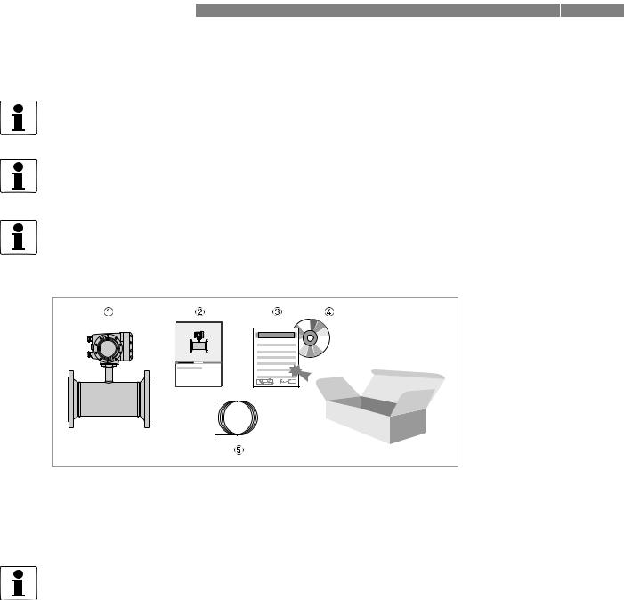
The device will arrive in two cartons. One carton contains the converter and one carton contains the sensor.
Figure 2-1: Scope of delivery - compact version
1Ordered flowmeter
2Product documentation
3Factory calibration certificate
4CD-ROM with product documentation in available languages
5Signal cable (remote versions only)
INFORMATION!
Assembly materials and tools are not part of the delivery. Use the assembly materials and tools in compliance with the applicable occupational health and safety directives.
12 |
www.krohne.com |
11/2013 - 4002037702 - HB OPTISONIC 3400 -en-R02 |
|
|
DEVICE DESCRIPTION 2 |
|
OPTISONIC 3400 |
|
|
|
|
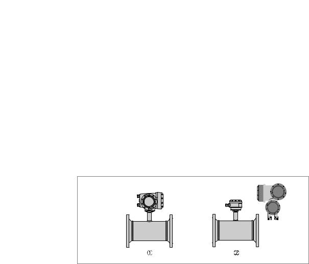
2.2 Device description
This ultrasonic flowmeter is designed for the continuous measurement of actual volume flow, mass flow, flow speed, velocity of sound, gain, SNR and diagnosis value.
Exclusively for measuring conductive and / or non-conductive fluids in closed, completely filled pipeline circuits.
Your measuring device is supplied ready for operation. The factory settings for the operating data have been made in accordance with your order specifications.
The following version is available:
•Compact version (the signal converter is mounted directly on the measuring sensor)
•Remote version (electrical connection to the measuring sensor via signal cable)
1Compact version
2Remote version
11/2013 - 4002037702 - HB OPTISONIC 3400 -en-R02 |
www.krohne.com |
13 |
2 DEVICE DESCRIPTION |
OPTISONIC 3400 |
|
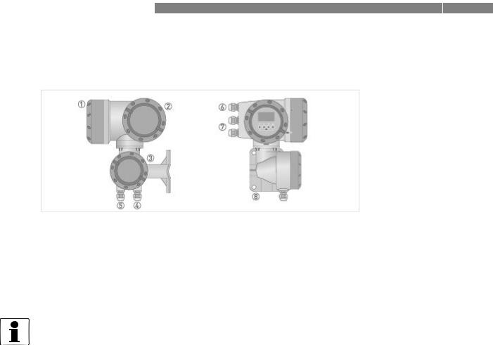
2.2.1 Field housing |
|
|
Figure 2-2: Construction of the field housing
1Cover for electronics and display
2Cover for power supply and inputs/outputs terminal compartment
3Cover for measuring sensor terminal compartment
4Use cable entry 4 or 5 for measuring sensor signal cable
5(see 4)
6Cable entry for power supply
7Cable entry for inputs and outputs
8Mounting plate for pipe and wall mounting
INFORMATION!
Each time a housing cover is opened, the thread should be cleaned and greased.
Use only resin-free and acid-free grease.
Ensure that the housing gasket is properly fitted, clean and undamaged.
14 |
www.krohne.com |
11/2013 - 4002037702 - HB OPTISONIC 3400 -en-R02 |
|
|
DEVICE DESCRIPTION 2 |
|
OPTISONIC 3400 |
|
|
|
|
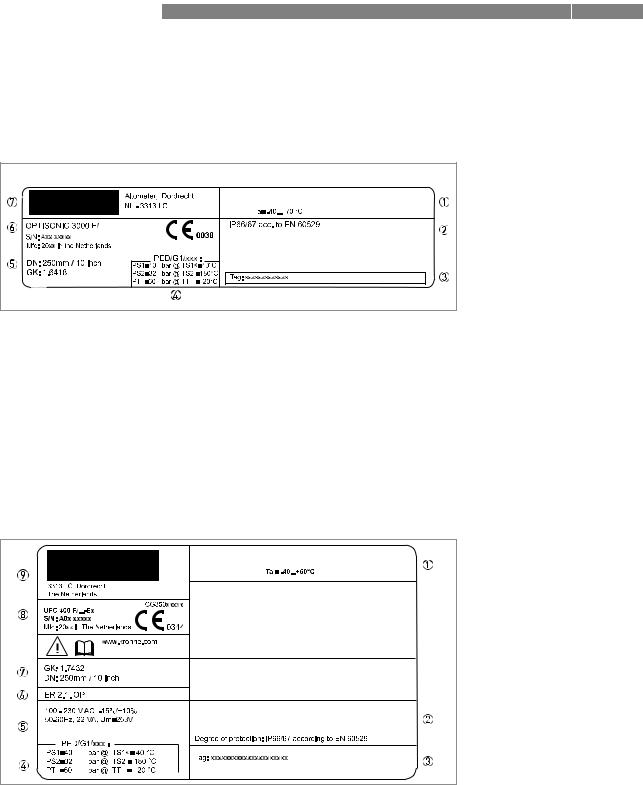
2.3 Nameplates
INFORMATION!
Look at the device nameplate to ensure that the device is delivered according to your order. Check for the correct supply voltage printed on the nameplate.
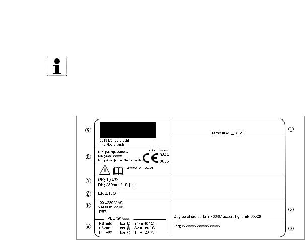
2.3.1 Example of nameplate for the compact version
Figure 2-3: Example of nameplate for the compact version
1Ambient temperature
2Protection class
3Tag number
4PED data, type I / II / II or SEP
5Mains supply data
6Electronic revision number
7Calibration data
8Type designation of the flowmeter and CE sign with number(s) of notified body / bodies
9Name and address of the manufacturer
11/2013 - 4002037702 - HB OPTISONIC 3400 -en-R02 |
www.krohne.com |
15 |
2 DEVICE DESCRIPTION |
OPTISONIC 3400 |
|
2.3.2 Nameplate for the measuring sensor (field version)
Examples for measuring sensor versions in Standard version.
1.Ambient temperature
2.Protection class
3.Tag number
4.PED data, type I / II / II or SEP
5.Calibration data
6.Type designation of the flowmeter and CE sign with number(s) of notified body / bodies
7.Name and address of the manufacturer
2.3.3Examples of nameplates on the signal converter (field version)
Figure 2-4: Examples of nameplates on the signal converter (field version)
1Ambient temperature
2Protection class
3Tag number
4PED data, type I / II / II or SEP
5Mains supply data
6Electronics revision numbers
7Calibration data
8Type designation of the flowmeter and CE sign with number(s) of notified body / bodies
9Name and address of the manufacturer
16 |
www.krohne.com |
11/2013 - 4002037702 - HB OPTISONIC 3400 -en-R02 |
|
|
DEVICE DESCRIPTION 2 |
|
OPTISONIC 3400 |
|
|
|
|
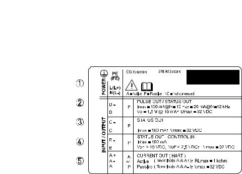
Electrical connection data of inputs/outputs (example of basic version)
1Power supply (AC: L and N, DC: L+ and L-, PE for ≥ 24V AC, FE for ≤ 24 VAC and DC)
2Connection data of connection terminal D/D-
3Connection data of connection terminal C/C-
4Connection data of connection terminal B/B-
5Connection data of connection terminal A/A-, A+ only operable in basic version
•A = active mode; the signal converter supplies the power for connection of the subsequent devices
•P = passive mode; external power supply required for operation of the subsequent devices
•N/C = connection terminals not connected
11/2013 - 4002037702 - HB OPTISONIC 3400 -en-R02 |
www.krohne.com |
17 |
3 INSTALLATION |
OPTISONIC 3400 |
|
3.1 General notes on installation
INFORMATION!
Inspect the cartons carefully for damages or signs of rough handling. Report damage to the carrier and to the local office of the manufacturer.
INFORMATION!
Do a check of the packing list to make sure that you have all the elements given in the order.
INFORMATION!
Look at the device nameplate to ensure that the device is delivered according to your order. Check for the correct supply voltage printed on the nameplate.
3.2Storage
•Store the device in a dry, dust-free location.
•Avoid continuous direct sunlight.
•Store the device in its original packaging.
•Storage temperature: -50...+70°C / -58...+158°F
3.3Transport
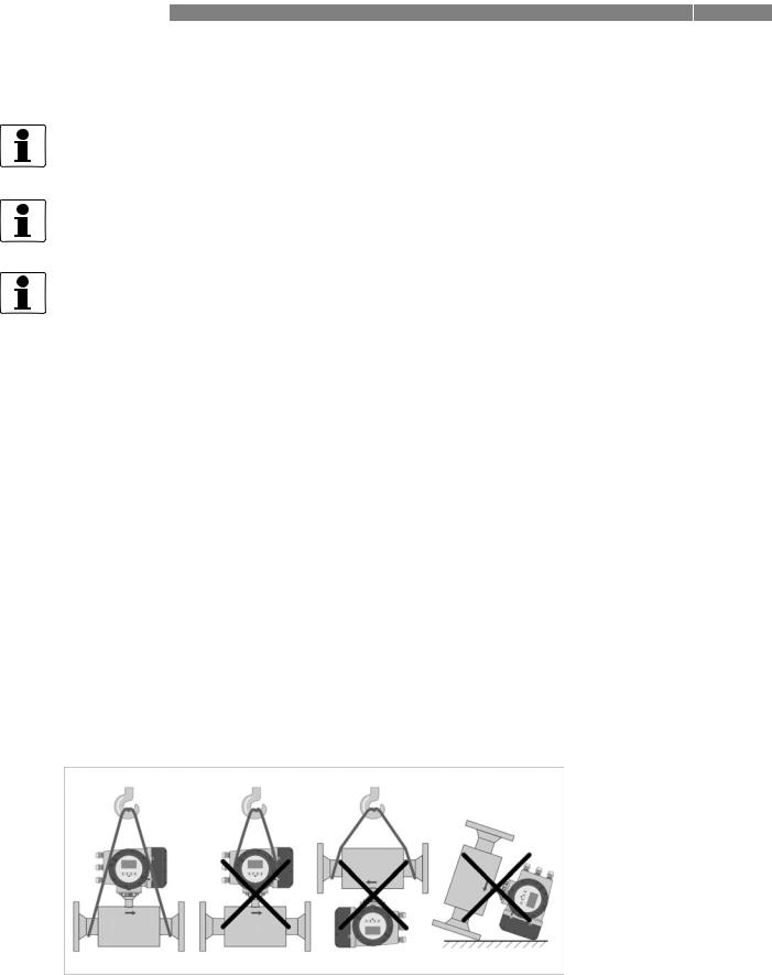
Signal converter
• Do not lift the signal converter by the cable glands.
Measuring sensor
•Do not lift the measuring sensor by the connection box.
•Use hoisting belts only.
•To transport flange devices, use lifting straps. Wrap these around both process connections.
Figure 3-1: Transport
18 |
www.krohne.com |
11/2013 - 4002037702 - HB OPTISONIC 3400 -en-R02 |
|
|
INSTALLATION 3 |
|
OPTISONIC 3400 |
|
|
|
|
3.4 Pre-installation requirements
INFORMATION!
To assure a quick, safe and uncomplicated installation, we kindly request you to make provisions as stated below.
Make sure that you have all necessary tools available:
•Allen key (4 mm)
•Small screwdriver
•Wrench for cable glands
•Wrench for pipe mounting bracket (remote version only) see; on page 25
•Torque wrench for installing flowmeter in pipeline
3.5General requirements
INFORMATION!
The following precautions must be taken to ensure reliable installation.
•Make sure that there is adequate space to the sides.
•Protect the signal converter from direct sunlight and install a sun shade if necessary.
•Signal converters installed in control cabinets require adequate cooling, e.g. by fan or heat exchanger.
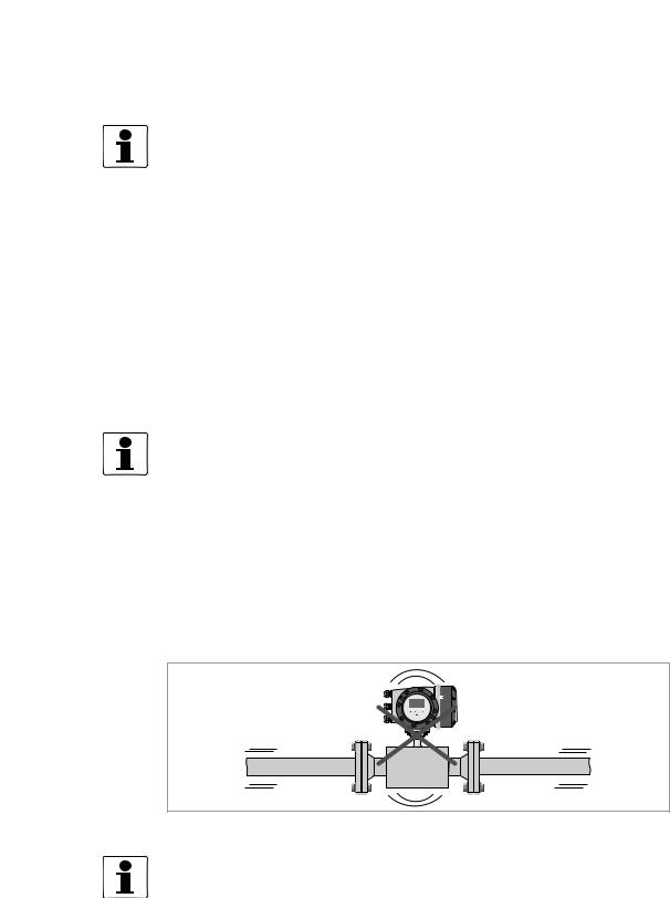
•Do not expose the signal converter to intense vibration. The flowmeters are tested for a vibration level in accordance with IEC 68-2-6.
3.5.1Vibration
Figure 3-2: Avoid vibrations
INFORMATION!
In case of expected vibrations, please install a field version.
11/2013 - 4002037702 - HB OPTISONIC 3400 -en-R02 |
www.krohne.com |
19 |
3 INSTALLATION
3.6 Installation conditions
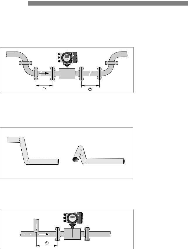
3.6.1 Inlet and outlet
OPTISONIC 3400 
Figure 3-3: Recommended inlet and oulet
1Refer to chapter "Bends in 2 or 3 dimensions"
2≥ 3 DN
3.6.2Bends in 2 or 3 dimensions
Figure 3-4: 2 and 3 dimensional bends, in front of flowmeter
1Bends in 2 dimensions: ≥ 5 DN; bends in 3 dimensions: ≥ 10 DN
3.6.3T-section
Figure 3-5: Distance behind a T-section
1 ≥ 5 DN
20 |
www.krohne.com |
11/2013 - 4002037702 - HB OPTISONIC 3400 -en-R02 |

|
|
INSTALLATION 3 |
|
OPTISONIC 3400 |
|
|
|
|
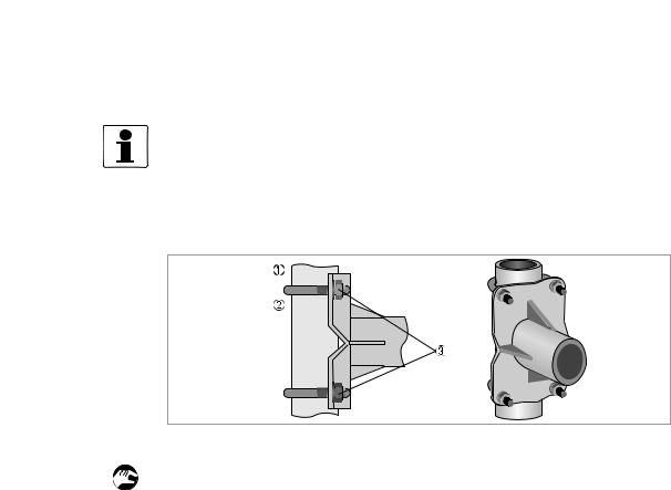
3.6.4 Bends
Figure 3-6: Installation in bending pipes
Figure 3-7: Installation in bending pipes
3.6.5 Open feed or discharge
Figure 3-8: Open discharge
Install meter on a lowered section of the pipe to ensure a full pipe condition through the meter.
11/2013 - 4002037702 - HB OPTISONIC 3400 -en-R02 |
www.krohne.com |
21 |
3 INSTALLATION |
OPTISONIC 3400 |
|
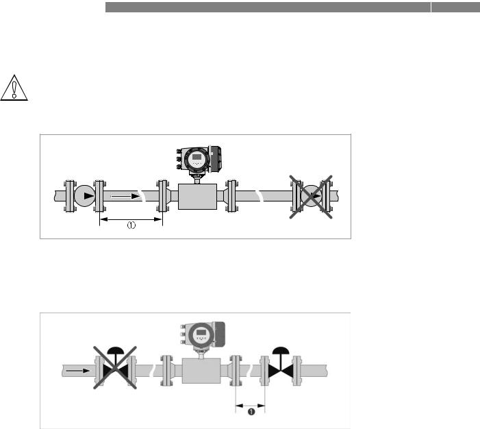
3.6.6 Position of pump
CAUTION!
Never install flowmeter at a pump suction side in order to avoid cavitation or flashing in the flowmeter.
Figure 3-9: Position of pump
1≥ 15 DN
3.6.7Control valve
Figure 3-10: Installation in front of a control valve
1 ≥ 20 DN
22 |
www.krohne.com |
11/2013 - 4002037702 - HB OPTISONIC 3400 -en-R02 |
|
|
INSTALLATION 3 |
|
OPTISONIC 3400 |
|
|
|
|
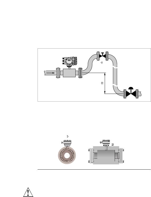
3.6.8 Down going pipeline over 5 m /16 ft length
Install air vent downstream of the flowmeter to prevent vacuum. Although this will not harm the meter, it may cause gases to come out of solution (cavitate) and interfere with proper measurements.
Figure 3-11: Down going pipeline over 5 m / 16 ft length
1≥ 5 m / 16 ft
2Install air vent
3.6.9Insulation
Figure 3-12: Insulation
1Connection box
2Insulation area
WARNING!
The flow sensor can be insulated completely, except for the connection box. (Ex: maximum temperature, refer to Ex supplement)
For devices used in hazardous area, additional maximum temperature and insulation precautions apply. Please refer to the Ex documentation!
11/2013 - 4002037702 - HB OPTISONIC 3400 -en-R02 |
www.krohne.com |
23 |
3 INSTALLATION |
OPTISONIC 3400 |
|
3.7 Mounting
3.7.1 Flange deviation
CAUTION!
Max. permissible deviation of pipe flange faces:
Lmax - Lmin ≤ 0.5 mm / 0.02"
Figure 3-13: Flange deviation
1Lmax
2Lmin
3.7.2Mounting position
Figure 3-14: Horizontal and vertical mounting
24 |
www.krohne.com |
11/2013 - 4002037702 - HB OPTISONIC 3400 -en-R02 |
|
|
INSTALLATION 3 |
|
OPTISONIC 3400 |
|
|
|
|
3.8 Mounting the field housing, remote version
INFORMATION!
Assembly materials and tools are not part of the delivery. Use the assembly materials and tools in compliance with the applicable occupational health and safety directives.
3.8.1 Pipe mounting
Figure 3-15: Pipe mounting of the field housing
1 Fix the signal converter to the pipe.
2Fasten the signal converter using standard U-bolts and washers.
3Tighten the nuts.
11/2013 - 4002037702 - HB OPTISONIC 3400 -en-R02 |
www.krohne.com |
25 |
3 INSTALLATION |
OPTISONIC 3400 |
|
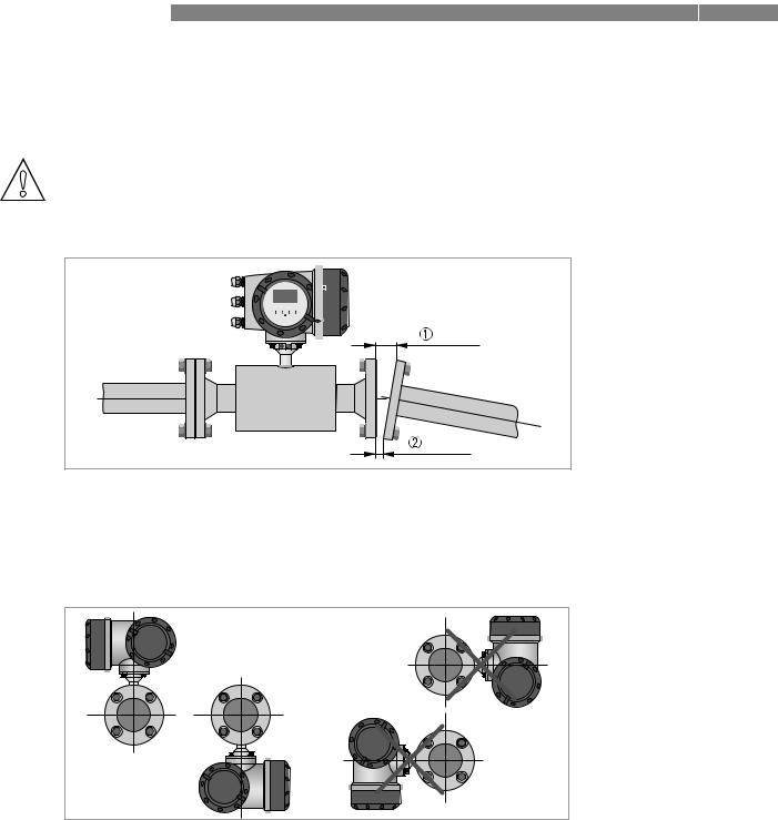
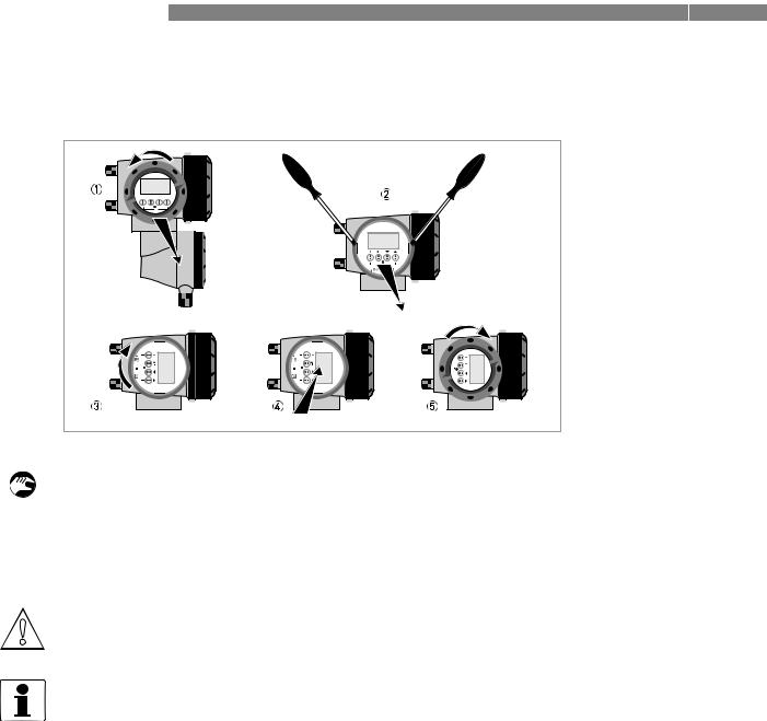
3.8.2 Turning the display of the field housing version
Figure 3-16: Turning the display of the field housing version
The display of the field housing version can be turned in 90° increments.
1Unscrew the cover from the display and operation control unit.
2Using a suitable tool, pull out the two metal puller devices to the left and right of the display.
3Pull out the display between the two metal puller devices and rotate it to the required position.
4Slide the display and then the metal puller devices back into the housing.
5Re-fit the cover and tighten it by hand.
CAUTION!
The ribbon cable of the display must not be folded or twisted repeatedly.
INFORMATION!
Each time a housing cover is opened, the thread should be cleaned and greased. Use only resinfree and acid-free grease.
Ensure that the housing gasket is properly fitted, clean and undamaged.
26 |
www.krohne.com |
11/2013 - 4002037702 - HB OPTISONIC 3400 -en-R02 |
|
|
ELECTRICAL CONNECTIONS 4 |
|
OPTISONIC 3400 |
|
|
|
|
4.1 Safety instructions
DANGER!
All work on the electrical connections may only be carried out with the power disconnected. Take note of the voltage data on the nameplate!
DANGER!
Observe the national regulations for electrical installations!
DANGER!
For devices used in hazardous areas, additional safety notes apply; please refer to the Ex documentation.
WARNING!
Observe without fail the local occupational health and safety regulations. Any work done on the electrical components of the measuring device may only be carried out by properly trained specialists.
INFORMATION!
Look at the device nameplate to ensure that the device is delivered according to your order. Check for the correct supply voltage printed on the nameplate.
4.2 Signal cable (remote versions only)
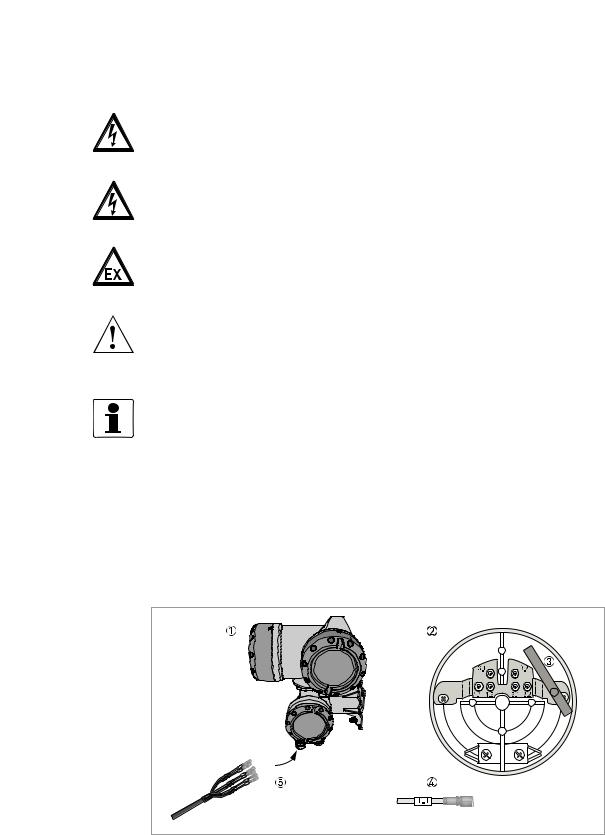
The flow sensor is connected to the signal converter via one signal cable, with 6 (labeled) inner coax cables for the connection of three acoustic paths.
Figure 4-1: Construction of field version
1Signal converter
2Open connection box
3Tool for releasing connectors
4Marking on cable
5Insert cable(s) into terminal compartment
11/2013 - 4002037702 - HB OPTISONIC 3400 -en-R02 |
www.krohne.com |
27 |
4 ELECTRICAL CONNECTIONS |
|
|
OPTISONIC 3400 |
|
|
|
|
|
CAUTION!
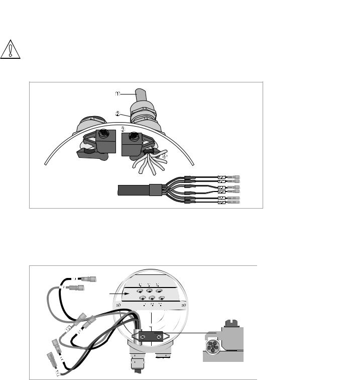
To ensure smooth functioning, always use the signal cable(s) included in the delivery.
Figure 4-2: Clamp the cables on the shielding bush
1Cables
2Cable glands
3Grounding clamps
4Cable with metal shielding bush
Electrical connection - Standard version
Figure 4-3: Connect the cables in the connection box of the flow sensor
28 |
www.krohne.com |
11/2013 - 4002037702 - HB OPTISONIC 3400 -en-R02 |
|
|
ELECTRICAL CONNECTIONS 4 |
|
OPTISONIC 3400 |
|
|
|
|
Connection of flow sensor type Cryogenic and XXT
Figure 4-4: Connect the cables in the connection box of the flow sensor
INFORMATION!
Connect the cable on connector with similar numeral marking
4.3 Power supply
WARNING!
When this device is intended for permanent connection to the mains.
It is required (for example for service) to mount an external switch or circuit breaker near the device for disconnection from the mains. It shall be easily reachable by the operator and marked as the disconnecting the device for this equipment.
The switch or circuit breaker and wiring has to be suitable for the application and shall also be in accordance with the local (safety) requirements of the (building) installation
(e.g. IEC 60947-1 / -3)
INFORMATION!
The power terminals in the terminal compartments are equipped with additional hinged lids to prevent accidental contact.
1100...230 VAC (-15% / +10%), 22 VA
224 VAC/DC (AC: -15% / +10%; DC: -25% / +30%), 22 VA or 12 W
DANGER!
The device must be grounded in accordance with regulations in order to protect personnel against electric shocks.
11/2013 - 4002037702 - HB OPTISONIC 3400 -en-R02 |
www.krohne.com |
29 |
4 ELECTRICAL CONNECTIONS |
|
|
OPTISONIC 3400 |
|
|
|
|
|
100…230 VAC
•Connect the protective ground conductor PE of the mains power supply to the separate terminal in the terminal compartment of the signal converter.
•Connect the live conductor to the L terminal and the neutral conductor to the N terminal.
24 VAC/DC
•Connect a functional ground FE to the separate U-clamp terminal in the terminal compartment of the signal converter.
•When connecting to functional extra-low voltages, provide a facility for protective separation (PELV) (VDE 0100 / VDE 0106 and/or IEC 364 / IEC 536 or relevant national regulations).
4.4Laying electrical cables correctly
Figure 4-5: Protect housing from dust and water
1 Lay the cable in a loop just before the housing.
2Tighten the screw connection of the cable entry securely.
3Never mount the housing with the cable entries facing upwards.
4Seal cable entries that are not needed with a plug.
30 |
www.krohne.com |
11/2013 - 4002037702 - HB OPTISONIC 3400 -en-R02 |
 Loading...