


CORIMASS
Instructions to use with
KROHNE SMART HART ®
Instruction Manual
Krohne SMART or HART® Communications Protocol and
MFC 081 / 085 Mass Flow Converters
Hart is a registered trademark of the HART Communication Foundation

Contents
1. |
The Krohne SMART System |
3 |
1.1 |
Description of Operation |
3 |
1.2 |
SMART overview |
3 |
1.3 |
Connecting the PC or Hand-held Communicator |
4 |
1.4 |
PC CONFIG Software Package |
5 |
1.5 |
Further Instruction Manuals |
5 |
2. |
The HART® Protocol |
6 |
2.1 |
Method of Operation |
6 |
2.2 |
Point to point Operation |
6 |
2.3 |
HART®Protocol Structure |
7 |
2.4 |
Hand-held Communicator |
9 |
2
1.The Krohne SMART System
1.1Description of operation
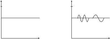
The interface for the Krohne Smart system is the current output. Bi-directional information can be transmitted via the current output cables. The current output signal (0/4 to 20 mA is not affected because the mean value of the signal containing the digital information is equal to zero.
The signals are superimposed by means of frequency shift keying (FSK), based on the Bell 202 communication standard. The digital transmission signal is formed from two frequencies: 2200 Hz = “0” and 1200 Hz = “1”.
MEASURED |
MEASURED |
VALUE |
VALUE |
20 mA |
20 mA |
|
2200 Hz |
1200 Hz |
|
“0” |
“1” |
0 mA |
0 mA |
|
TIME |
|
TIME |
CONVENTIONAL |
SMART FSK MODE |
|
The Smart technology will enable you to utilize its advantages for initial start up, maintenance work and to change settings. All parameters for new measuring devices (in this case, the mass flow meter or meters) or those to be changed can be defined and entered into the PC in the workshop. The stored data can then be downloaded to the mass flow meter and started up from the control room (via the cable marshalling rack).
The same applies to operation and maintenance. The status of the mass flow meter can be displayed on-line, or in test mode, the current output can be set to a specific value or values in order to test the whole circuit. If a converter is replaced, the parameter set from the data base (PC) can be downloaded into the new converter. This eliminates time consuming data entry and programming. The possibility of errors being incurred during programming is also eliminated.
1.2SMART overview
All Krohne Smart signal converters may be operated via PC. The transmission route may be up to 1600 m / 5250 ft long. The load between the coupling part of the PC and the converter output loop should be at least 100 ohms.
Note: This protocol is not compatible with HART â even though it uses a similar method of communication.
3
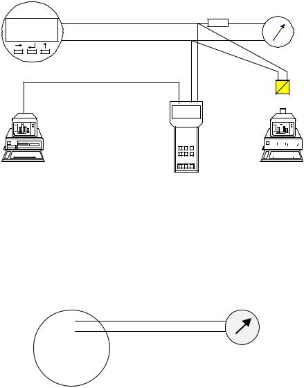
MFC 081/085 |
|
SMART |
0/4 - 20 mA + FSK |
LOAD
SMART Converter
Data can be transferred between a PC and MIC 500 or vice versa
|
|
|
|
|
|
|
|
|
|
|
|
|
|
|
|
|
|
|
|
|
|
|
|
|
|
|
|
|
|
|
MIC 500 |
|
|
|
|
|
|
|
|
Adaptor |
|||||||||||||||||||||
|
|
|
|
|
|
|||||||||||||||||||||||||
|
|
|
|
|
|
|
|
|
|
|
|
|
|
|
|
|
|
|
|
|
|
|
|
|
|
|
|
|
|
|
|
|
|
|
|
|
|
|
|
|
|
|
|
|
|
|
|
|
|
|
|
|
|
|
|
|
|
|
|
|
|
|
|
|
|
|
|
|
|
|
|
|
|
|
|
|
|
|
|
|
|
|
|
|
|
|
|
|
|
|
|
|
|
|
|
|
|
|
|
|
|
|
|
|
|
|
|
|
|
|
|
|
|
|
|
|
|
|
|
|
|
|
|
CONFIG Program communicates directly with converter
1.3Connecting the PC
The PC can only be connected to the first current output of the MFC 081/085, i.e. current output from terminals (5 (–) and 6 (+). The other current outputs that may be available (depending on options ordered) will not carry the FSK signal and the Smart system will not work. If another communication protocol option has been ordered, e.g. RS 485 or Profibus, then the Smart system will be inactive as the processor will only accommodate one communication protocol at a time.
5 |
– |
|
+ |
||
6 |
||
|
||
4 |
|
|
4.1 |
|
|
4.2 |
|
|
|
|
MFC 081/085
0/4 - 20 mA
 Smart always available on first current output only
Note:
This communication protocol is a Krohne designed protocol and for use with Krohne CONFIG Software package and not intended for use on non-Krohne equipment. The protocol description is thus also not available for distribution.
4
1.4PC CONFIG Software package
The VDI/VDE-GMA 2187 Guideline issued in Germany is the first attempt to define a mode of operation for signal converters including those of different makes. The operating unit is the PC through which the all Krohne Smart converters can be controlled and programmed. The signal converters are linked via a RS 232 interface at the PC. All Krohne Smart transducers can be operated using the Krohne PC “CONFIG” operator package.
Minimum PC requirements
∙PC, personal computer, with MSDos or compatible operating system
∙Disk drive: 3½”
∙Screen mode with 25 × 80 characters
∙Serial interface RS 232
∙No special requirements imposed on graphic adaptor (Hercules, EGA, VGA, etc.), the CONFIG program operates in the text mode so older PC’s can also be used.
Items supplied with Krohne PC operator package CONFIG
∙1 × 3½” diskette with complete CONFIG software
∙Smart converter or RS 232 adaptor (or RS 232 - RS 485 converter on request)
∙Smart cable, link between current output and Smart converter
∙Adaptor for 25-pin RS 232 interface at PC
Screen layout, operator control and functions
∙Operation via mouse or keyboard and hot keys
∙Screen layout and operator control modelled on the Microsoft Windows user interface
∙Connection set-up to Smart signal converters or the MIC 500 hand-held communicator
∙Diagnostics, detailed presentation of signal converter messages, and call of simulation functions (tests)
∙Change, compare, print and store instrument parameters
∙Dynamic representation of measured values and signal converter status
1.5Further Instruction Manuals
Krohne PC CONFIG Operating Manual |
Order No. 7.02196.71.00 |
These manuals should accompany the equipment when ordered.
5
2.The HART® Protocol
2.1Method of Operation
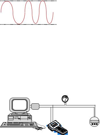
The HART® protocol operates using the frequency shift keying (FSK) principle, which is based on the Bell 202 [1] communication standard. The digital signal is made up from two frequencies - 1200 Hz and 2200 Hz, representing bits 1 and 0 respectively. Sine waves of these frequencies are superimposed on the DC analog signal cables to give simultaneous analog and digital communications. Because the average value of the FSK signal is always zero, the 4 - 20 mA signal is not affected.
This produces genuine, simultaneous communication with a response time of approximately 500 ms for each field device, without interrupting any analog signal transmission that might be taking place.
Up to two master devices may be connected to each HART® loop. The primary one is generally a management system or a PC while the secondary one can be a hand-held terminal
or laptop computer. A available to make field provided by gateways.
standard hand-held terminal - called the HART® Communicator - is operations as uniform as possible. Further networking options are
approx. +0.5 mA |
|
|
|
|
|
|
|||
|
|
|
|
||||||
|
|
|
|
|
|
|
|
||
|
0 |
|
|
|
|
|
|
analog signal |
|
|
|
|
|
|
|
||||
|
|
|
|
|
|
|
|
|
|
|
|
|
|
|
|
|
|
|
|
approx. +0.5 mA |
|
|
|
|
|||||
1200 Hz |
2200 Hz |
||||||||
|
|
|
|
|
|||||
|
|
|
|
|
|||||
|
|
|
|
|
“1” |
“0” |
|||
Simultaneous analog and digital signals
Because the mean harmonic signal value is zero, digital communication makes no difference to any existing analog signal as demonstrated in the figure above.
2.2Point to point operation
The figure below shows some examples of point-to-point mode. The conventional 4 - 20 mA signal continues to be used for analog transmission while measurement, adjustment and equipment data is transferred digitally.
The analog signal remains unaffected and can be used for control in the normal way. HART® data gives access to maintenance, diagnostic and other operational data.
Analog
HART interface
4 mA20
Up to 2 updates/sec
Digital |
MFC 081/085
Multiple Masters
6
2.3HART®Protocol Structure
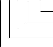
HART®follows the basic Open Systems Interconnection (OSI) reference model, developed by the International Organisation for Standardisation (ISO) [3]. The OSI model provides the structure and elements of a communication system. The HART®protocol uses a reduced OSI model, implementing only layers 1,2 and 7.
OSI Reference Model
Open Systems Interconnection
|
Layer |
Function |
® |
|
HART |
||
|
|
|
|
7 |
Application |
provides formatted data |
HART instructions |
|
|
|
|
6 |
Presentation |
converts data |
|
|
|
|
|
5 |
Session |
handles the dialogue |
|
|
|
|
|
4 |
Transport |
secures the transport |
|
|
|
connection |
|
3 |
Network |
establishes network |
|
|
|
connections |
|
2 |
Link |
establishes the data |
HART protocol |
|
|
link connection |
regulations |
|
|
|
|
1 |
Physical |
connects the equipment |
Bell 202 |
|
|
|
|
The HART®protocol implements layers 1,2 and 7 from the OSI model
Layer 1, the Physical layer, operates on the FSK principle, based on the Bell 202 communication standard:
Data transfer rate: 1200 bit/s
Logic ‘0’ frequency: 2200 Hz
Logic ‘1’ frequency: 1200 Hz
The vast majority of existing wiring is used for this type of digital communication. For short distances, unshielded, 0.2 mm2 two-wire lines are suitable. For longer distances (up to 1500 m), single, shielded bundles of 0.2 mm2 twisted pairs can be used. Beyond this, distances up to 3000 m can be covered using single, shielded, twisted 0.5 mm2 pairs.
A minimum resistance of 230 ohms must be available in the communication circuit.
Layer 2, the Link layer, establishes the format for a HART®message. HART®is a master/slave protocol. All the communication activities originate from a master, e.g. a display terminal. This addresses a field device (slave), which interprets the command message and sends a response.
7
The structure of these messages can be seen in the figure below. In multi-drop mode this can accommodate the addresses for several field devices and terminals.
Structure of a HART®message
Preamble |
SD |
AD |
CD |
BC |
Status |
Data |
Parity |
|
|
|
|
|
|
|
|
Field device and communication status (ONLY from field device to master)
Byte count
HART instruction
Display terminal and field device addresses
Start character
The HART message structure offers a high degree of data integrity
A specific size of operand is required to enable the field device to carry out the HART instruction. The byte count indicates the number of subsequent status and data bytes.
Layer 2 improves transmission reliability by adding the parity character derived from all the preceding characters; each character also receives a bit for odd parity.
The individual characters are: 1 start bit
8 data bits
1 bit for odd parity
1 stop bit
Layer 7, the Application layer, brings the HART instruction set into play. The master sends messages with requests for specified values, actual values and any other data or parameters available from the device. The field device interprets these instructions as defined in the HART protocol. The response message provides the master with status information and data from the slave.
To make interaction between HART compatible devices as efficient as possible, classes of conformity have been established for masters, and classes of commands for slaves. There are six classes of conformity for a master as seen in the figure below.
8

Classes of instruction and classes of conformity |
|
|
|
|||
|
|
|
|
|
|
|
|
UNIVERSAL |
|
|
|
Read Measured |
|
|
|
|
|
Variable |
|
|
|
COMMANDS |
|
|
|
Read Universal |
|
|
|
|
|
|
Information |
|
|
COMMON |
|
|
|
Write Standard |
|
|
|
|
|
Parameters |
|
|
|
PRACTICE |
|
|
|
|
|
|
|
|
|
|
|
|
|
|
|
|
Read Device-Specific |
|
|
|
COMMANDS |
|
|
|
|
|
|
|
|
|
Information |
|
|
|
|
|
|
|
|
|
|
|
|
|
|
|
|
|
DEVICE |
|
|
|
Write Selected |
|
|
|
|
|
Parameters |
|
|
|
SPECIFIC |
|
|
|
|
|
|
|
|
|
|
|
|
|
|
|
|
|
|
|
|
COMMANDS |
|
|
|
Read and Write |
|
|
|
|
|
Entire Database |
|
|
|
|
|
|
|
|
|
|
|
|
|
|
|
|
|
|
|
|
|
|
|
For slave devices, logical, uniform communication is provided by the following command sets:
Universal commands understood by all field devices
Common practice commands
provide functions which can be carried out by many, though not all, field devices. Together, these commands comprise a library of the most common field device functions.
Device-specific commands
provide functions which are restricted to an individual device, permitting special features to be incorporated that are accessible by all users.
Examples of all three command sets can usually be found in a field device, including all universal commands, some common-practice commands and any necessary device-specific commands.
2.4Hand-held Communicator
A standard HART®hand-held communicator may be used on Krohne equipment. The operating instructions for this communicator is not supplied by Krohne and should accompany the hand-held communicator when purchased.
A HART® Communicator is available from Krohne and may be purchased with all customer requested DDL’s already downloaded to the instrument.
The Krohne CONFIG software package can also be supplied for HART®compatible instruments. The functions are similar to that described in Sect. 1.4 (available end 1996).
Further information on HART®may be found in the HART®Field Communication Protocol book available on request.
The Corimass MFC 081/085 HART®protocol is available from Krohne on request. Should you require any further information, please contact your nearest Krohne office or Product Management in Duisburg, Germany.
9
10
Krohne RS 485
Bus-Protocol
Pages 11-23
Contents
1. |
General |
12 |
2. |
Technical Specifications |
12 |
3. |
Connection of instruments on the BUS system |
13 |
3.1 |
Single Master/Slave configuration (Non Ex applications only) |
13 |
3.2 |
Single Master/Slave configuration (Ex applications) |
13 |
3.3 |
Multi-drop applications |
14 |
3.4 |
Bus termination |
14 |
3.5 |
Network Biasing Resistors |
15 |
4. |
Using the Current output with the RS 485 Bus |
16 |
5. |
Converter configuration |
17 |
6. |
Transmission format |
18 |
7. |
Format of the data field |
18 |
8. |
Format of the data blocks |
19 |
8.1 |
Measurement Block |
19 |
8.2 |
Error list |
20 |
9. |
Reference documentation |
21 |
11
 Loading...