


2008 Kia Sedona
2008 BRAKES ABS (Anti-Lock Brake System) - Sedona
2008 BRAKES
ABS (Anti-Lock Brake System) - Sedona
COMPONENTS
Fig. 1: Identifying ABS (Anti-Lock Brake System) Components
Courtesy of KIA MOTORS AMERICA, INC.
DESCRIPTION
This specification applies to HCU (Hydraulic Control Unit) and ECU (Electronic Control Unit) of the HECU (Hydraulic and Electronic Control Unit).
This specification is for the wiring design and installation of ABS/TCS/ESC ECU.

2008 Kia Sedona
2008 BRAKES ABS (Anti-Lock Brake System) - Sedona
This unit has the functions as follows.
{Input of signal from Pressure sensor, Steering angle sensor, Yaw & Lateral G sensor, the wheel speed sensors attached to each wheel.
{Control of braking force/traction force/yaw moment.
{Failsafe function.
{Self-diagnosis function.
{Interface with the external diagnosis tester.
Installation position: engine compartment
{Brake tube length from master cylinder port to HECU inlet port should be max. 1 m
{The position should not be close to the engine block and not lower than the wheel.
OPERATION
The ECU shall be put into operation by switching on the operating voltage (IGN).
On completion of the initialization phase, the ECU shall be ready for operation.
In the operating condition, the ECU shall be ready, within the specified limits (voltage and temperature), to process the signals offered by the various sensors and switches in accordance with the control algorithm defined by the software and to control the hydraulic and electrical actuators.
WHEEL SENSOR SIGNAL PROCESSING
The ECU shall receive wheel speed signal from the four active wheel sensors.
The wheel signals are converted to voltage signal by the signal conditioning circuit after receiving current signal from active wheel sensors and given as input to the MCU.
SOLENOID VALVE CONTROL
When one side of the valve coil is connected to the positive voltage that is provided through the valve relay and the other side is connected to the ground by the semiconductor circuit, the solenoid valve goes into operation.
The electrical function of the coils are always monitored by the valve test pulse under normal operation conditions.
VOLTAGE LIMITS
{Overvoltage
When overvoltage is detected (above 16.8V), the ECU switches off the valve relay and shuts down the system.
2008 Kia Sedona
2008 BRAKES ABS (Anti-Lock Brake System) - Sedona
When voltage is returned to operating range, the system goes back to the normal condition after the initialization phase.
{Undervoltage
In the event of undervoltage (below 9.3V), ABS control shall be inhibited and the warning lamp shall be turned on.
When voltage is returned to operating range, the warning lamp is switched off and ECU returns to normal operating mode.
PUMP MOTOR CHECKING
The ECU performs a pump motor test at a speed of 15km/h once after IGN is switched on.
DIAGNOSTIC INTERFACE
Failures detected by the ECU are encoded on the ECU, stored in a EEPROM and read out by diagnostic equipment when the ignition switch is turned on.
The diagnosis interface can also be used for testing the ECU during production of the ECU and for actuating the HCU (Air-bleeding line or Roll and Brake Test line).
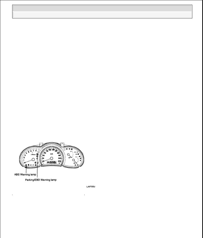
WARNING LAMP MODULE
Fig. 2: Identifying Warning Lamp Module
Courtesy of KIA MOTORS AMERICA, INC.
1.ABS WARNING LAMP MODULE
The active ABS warning lamp module indicates the self-test and failure status of the ABS. The ABS warning lamp shall be on:
{During the initialization phase after IGN ON (continuously 3 seconds).
{In the event of inhibition of ABS functions by failure.
2008 Kia Sedona
2008 BRAKES ABS (Anti-Lock Brake System) - Sedona
{During diagnostic mode.
{When the ECU Connector is separated from ECU.
2.PARKING/EBD WARNING LAMP MODULE
The active EBD warning lamp module indicates the self-test and failure status of the EBD. However, in case the Parking Brake Switch is turned on, the EBD warning lamp is always turned on regardless of EBD functions. The EBD warning lamp shall be on:
{During the initialization phase after IGN ON (continuously 3 seconds).
{When the Parking Brake Switch is ON or brake fluid level is low.
{When the EBD function is out of order.
{During diagnostic mode.
{When the ECU Connector is separated from ECU.
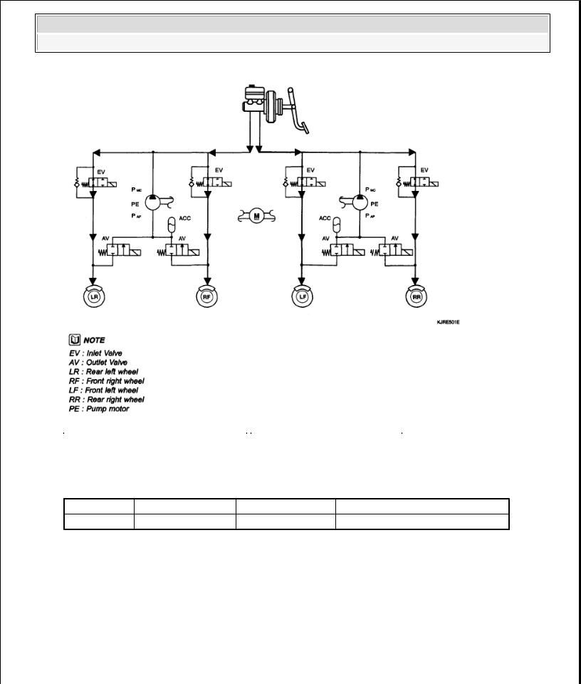
ABS CONTROL
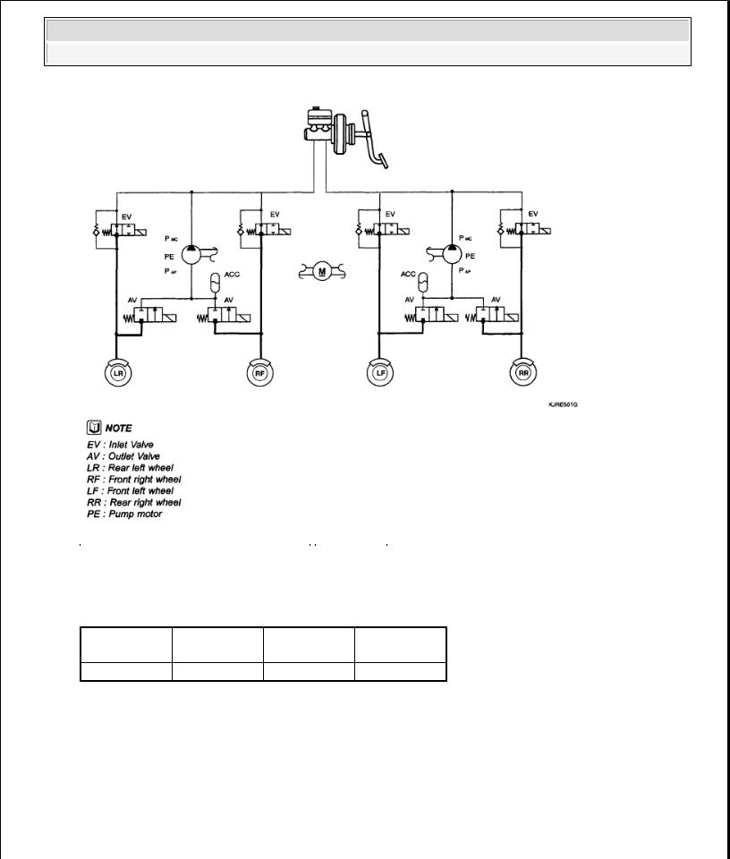
1. NORMAL BRAKING without ABS
OPERATION CHART |
|
|
|
|
Inlet valve |
Outlet valve |
Pump motor |
|
(EV) |
(AV) |
|
Operation |
Open |
Close |
OFF |
2008 Kia Sedona
2008 BRAKES ABS (Anti-Lock Brake System) - Sedona
Fig. 3: ABS Control Circuit Diagram - Normal Braking Without ABS Courtesy of KIA MOTORS AMERICA, INC.
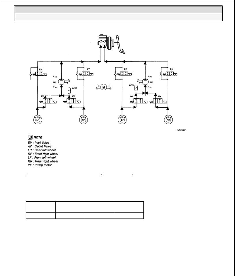
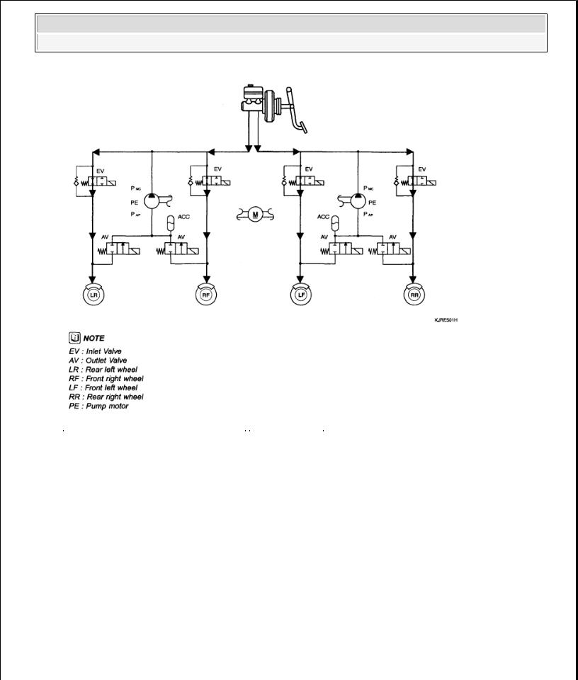
2. DECREASE MODE
OPERATION CHART |
|
|
|
|
Inlet valve (EV) |
Outlet valve (AV) |
Pump motor |
Operation |
Close |
Open |
ON (Motor speed control) |
2008 Kia Sedona
2008 BRAKES ABS (Anti-Lock Brake System) - Sedona
Fig. 4: ABS Control Circuit Diagram - Decrease Mode
Courtesy of KIA MOTORS AMERICA, INC.
3.HOLD MODE
OPERATION CHART
|
Inlet valve |
Outlet valve |
Pump motor |
|
(EV) |
(AV) |
|
Operation |
Close |
Close |
OFF |
2008 Kia Sedona
2008 BRAKES ABS (Anti-Lock Brake System) - Sedona
Fig. 5: ABS Control Circuit Diagram - Hold Mode
Courtesy of KIA MOTORS AMERICA, INC.
4.INCREASE MODE
OPERATION CHART
|
Inlet valve |
Outlet valve |
Pump motor |
|
(EV) |
(AV) |
|
Operation |
Open |
Close |
OFF |
2008 Kia Sedona
2008 BRAKES ABS (Anti-Lock Brake System) - Sedona
Fig. 6: ABS Control Circuit Diagram - Increase Mode
Courtesy of KIA MOTORS AMERICA, INC.
ABS CIRCUIT DIAGRAM

2008 Kia Sedona
2008 BRAKES ABS (Anti-Lock Brake System) - Sedona
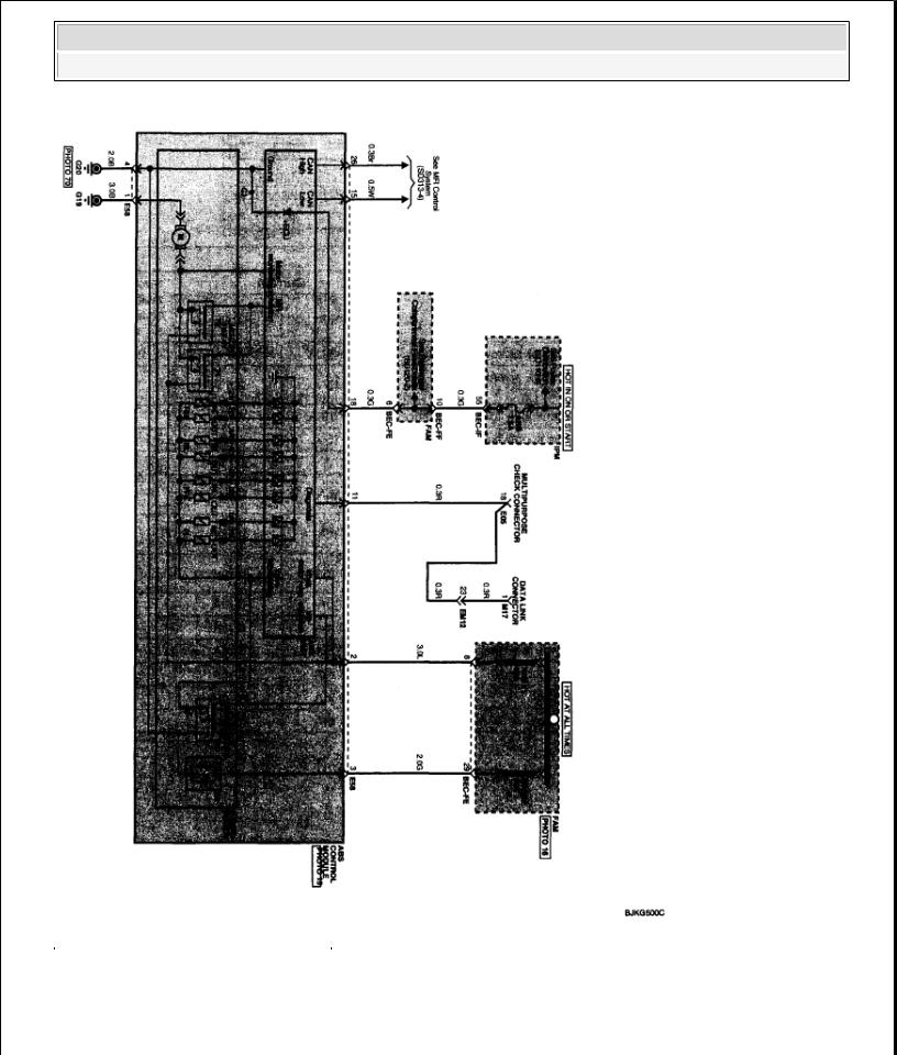
Fig. 7: ABS Circuit Diagram (1 Of 2)
Courtesy of KIA MOTORS AMERICA, INC.
2008 Kia Sedona
2008 BRAKES ABS (Anti-Lock Brake System) - Sedona
Fig. 8: ABS Circuit Diagram (2 Of 2)
Courtesy of KIA MOTORS AMERICA, INC.
ECU CONNECTOR
INPUT/OUTPUT (ABS)
2008 Kia Sedona
2008 BRAKES ABS (Anti-Lock Brake System) - Sedona
Fig. 9: Identifying ECU Connector Terminals Courtesy of KIA MOTORS AMERICA, INC.
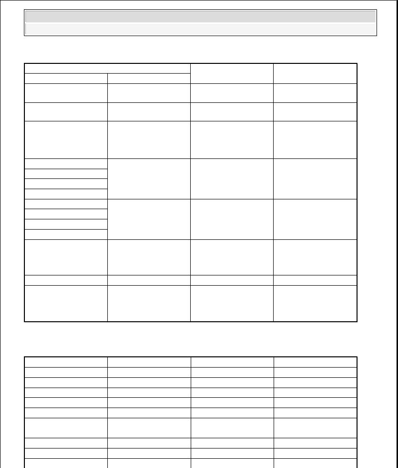
ECU CONNECTOR TERMINALS REFERENCE CHART
Wire No. |
Designation |
Current |
|
|
max |
min |
|||
|
|
|||
1 |
Ground for |
20-39 A |
10 A |
|
|
recirculation pump |
|
|
|
|
Ground for |
5-15 A |
2.5 A |
4solenoid valves and ECU
max. permissible |
min. leakage |
wire resistance |
resistance R_P |
R_L (mohms) |
(kohms) |
10 |
|
10 |
|
2 |
Voltage supply for |
20-39 A |
10 A |
10 |
200 |
|
pump motor |
|
|
|
|
3 |
Voltage supply for |
5-15 A |
2 A |
10 |
200 |
|
solenoid valves |
|
|
|
|
18 |
Voltage for hybrid |
1 A |
500 mA |
60 |
200 |
|
ECU |
|
|
|
|
|
signal wheel speed |
6 mA |
16 mA |
250 |
200 to ground |
5,10,17,19 |
sensor FL, FR, RL, |
|
|
|
1.5M to bat |
|
RR |
|
|
|
|
16,9,6,8
14,24
11
22
Voltage supply for |
6 mA |
16 mA |
250 |
200 to ground |
the active wheel |
|
|
|
1.5M to bat |
speed sensor FL, |
|
|
|
|
FR, RL, RR |
|
|
|
|
wheel speed sensor |
20 mA |
10 mA |
250 |
200 |
output (FR, RL) |
|
|
|
|
Diagnostic wire K |
6 mA |
3 mA |
250 |
200 |
ABS-warning lamp |
30 mA |
5 mA |
250 |
200 |
actuation |
|
|
|
|
12 |
EBD-warning |
30 mA |
5 mA |
250 |
200 |
|
lamp actuation |
|
|
|
|
20 |
brake light switch |
10 mA |
5 mA |
250 |
200 |
15 |
CAN Low |
30 mA |
20 mA |
250 |
200 |
26 |
CAN High |
30 mA |
20 mA |
250 |
200 |
ABS HECU CONNECTOR
|
2008 Kia Sedona |
||
|
2008 BRAKES ABS (Anti-Lock Brake System) - Sedona |
||
ABS HECU CONNECTOR REFERENCE CHART |
|||
Connector terminal |
Specification |
||
Number |
Description |
||
|
|||
1 |
Ground for recirculation |
Current range: Min.10A |
|
pump |
Max.20-39A |
||
|
|||
4 |
Ground for solenoid |
Current range: Min. 2.5A |
|
valves and ECU |
Max. 5-15A |
||
|
|||
2 |
Voltage supply for pump |
|
|
|
motor |
Battery voltage |
|
3 |
Voltage supply for |
||
|
|||
16 |
solenoid valves |
|
|
Voltage supply for the |
|
||
9 |
|
||
active wheel speed sensor |
Battery voltage |
||
6 |
|||
FL, FR, RL, RR |
|
||
8 |
|
||
|
|
||
5 |
|
Voltage (High): 0.89-1.26 |
|
10 |
signal wheel speed sensor |
V |
|
17 |
FL, FR, RL, RR |
Voltage (Low): 0.44-0.63 |
|
19 |
|
V |
|
|
|
Voltage (High) > or = 0.8 |
|
11 |
Diagnostic wire K |
* IG ON |
|
Voltage (Low) < or = 0.2 |
|||
|
|
||
|
|
* IG ON |
|
18 |
Voltage for hybrid ECU |
Battery voltage |
|
|
|
Voltage (High) > or = 0.8 |
|
20 |
Brake light switch |
* IG ON |
|
Voltage (Low) < or = 0.3 |
|||
|
|
||
* IG ON
Condition
Always
Always
Always
IG ON
On driving
On Scan Tool communication
KEY ON/OFF
BRAKE ON/OFF
SENSOR OUTPUT ON SCAN TOOL (ABS) |
|
|
|
SENSOR REFERENCE CHART |
|
|
|
|
Description |
Abbreviation |
Unit |
1 |
Vehicle speed sensor |
VEH. SPD |
Km/h |
2 |
Battery voltage |
BATT. VOL |
V |
3 |
FL Wheel speed sensor |
FL WHEEL |
Km/h |
4 |
FR Wheel speed sensor |
FR WHEEL |
Km/h |
5 |
RL Wheel speed sensor |
RL WHEEL |
Km/h |
6 |
RR Wheel speed sensor |
RR WHEEL |
Km/h |
7 |
ABS Warning lamp |
ABS LAMP |
- |
8 |
EBD Warning lamp |
EBD LAMP |
- |
9 |
Brake Lamp |
B/LAMP |
- |
10 |
Pump relay state |
PUMP RLY |
- |

2008 Kia Sedona
2008 BRAKES ABS (Anti-Lock Brake System) - Sedona
11 |
Valve relay state |
VALVE RLY |
- |
12 |
Motor |
MOTOR |
- |
13 |
Front Left valve (IN) |
FL INLET |
- |
14 |
Front Right valve (IN) |
FR INLET |
- |
15 |
Rear Left valve (IN) |
RL INLET |
- |
16 |
Rear Right valve (IN) |
RR INLET |
- |
17 |
Front Left valve (OUT) |
FL OUTLET |
- |
18 |
Front Right valve (OUT) |
FR OUTLET |
- |
19 |
Rear Left valve (OUT) |
RL OUTLET |
- |
20 |
Rear Right valve (OUT) |
RR OUTLET |
- |
STANDARD FLOW OF DIAGNOSTIC TROUBLESHOOTING
Fig. 10: Standard Flow Of Diagnostic Troubleshooting Chart
Courtesy of KIA MOTORS AMERICA, INC.
NOTES WITH REGARD TO DIAGNOSIS
The phenomena listed in the following table are not abnormal.
TROUBLESHOOTING REFERENCE CHART |
|
Phenomenon |
Explanation |
System check sound |
When starting the engine, a thudding sound can |
|
sometimes be heard coming from inside the engine |
|
compartment. This is because the system operation |
|
|
2008 Kia Sedona
2008 BRAKES ABS (Anti-Lock Brake System) - Sedona
ABS operation sound
ABS operation (Long braking distance)
check is being performed.
1.Sound of the motor inside the ABS hydraulic unit operation (whine).
2.Sound is generated along with vibration of the brake pedal (scraping).
3.When ABS operates, sound is generated from the vehicle chassis due to repeated brake application and release (Thump: suspension; squeak: tires)
For road surfaces such as snow-covered and gravel roads, the braking distance for vehicles with ABS can sometimes be longer than that for other vehicles. Accordingly, advise the customer to drive safely on such roads by lowering the vehicle speed.
Diagnosis detection conditions can vary depending on the diagnosis code. When checking the trouble symptom after the diagnosis code has been erased, ensure that the requirements listed in "Comment" are met.
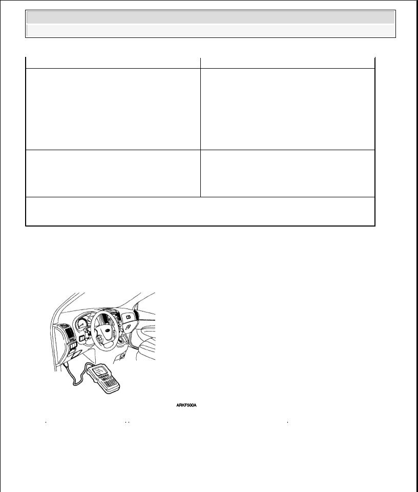
SCAN TOOL CHECK
1.Turn the ignition switch OFF.
2.Connector the Scan tool to the 16P data link connector located the driver's side kick panel.
Fig. 11: Connecting HI-Scan Pro Connector To Data Link Connector
Courtesy of KIA MOTORS AMERICA, INC.
3.Turn the ignition switch ON.
4.Check for DTC using the Scan tool
5.After completion trouble of the repair or correction of the problem, erase the stored fault codes using the scan tool.
6.Disconnect the Scan tool from the 16P data link connector.
2008 Kia Sedona
2008 BRAKES ABS (Anti-Lock Brake System) - Sedona
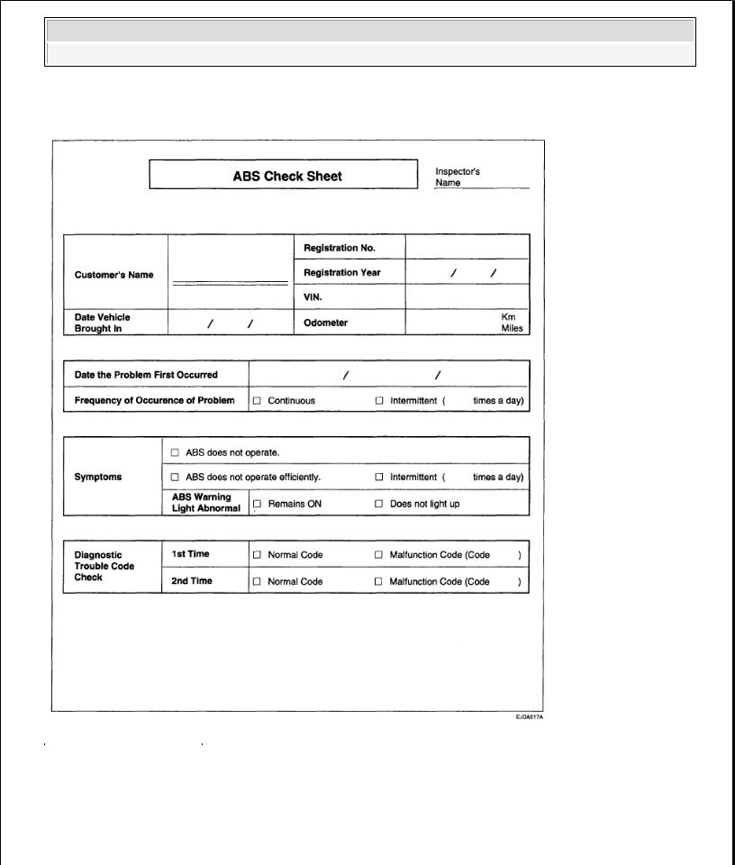
ABS CHECK SHEET
Fig. 12: ABS Check Sheet
Courtesy of KIA MOTORS AMERICA, INC.
PROBLEM SYMPTOMS TABLE
If a normal code is displayed during the DTC check but the problem still occurs, check the circuits for each problem symptom in the order given in the table below and proceed to the relevant troubleshooting page.

2008 Kia Sedona
2008 BRAKES ABS (Anti-Lock Brake System) - Sedona
PROBLEM SYMPTOMS TABLE |
|
|
Symptom |
|
Suspect Area |
ABS does not operate. |
Only when 1. -4. are all normal and the problem is still occurring, |
|
|
replace the HECU. |
|
|
1. |
Check the DTC reconfirming that the system is operating to |
|
|
specifications. |
|
2. |
Power source circuit. |
|
3. |
Speed sensor circuit. |
|
4. |
Check the hydraulic circuit for leakage. |
ABS does not operate |
Only when 1. -4. are all normal and the problem is still occurring, |
|
intermittently. |
replace the ABS actuator assembly. |
|
|
1. |
Check the DTC reconfirming that the system is operating to |
|
|
specifications. |
|
2. |
Wheel speed sensor circuit. |
|
3. |
Stop lamp switch circuit. |
|
4. |
Check the hydraulic circuit for leakage. |
Communication with Scan tool is not possible.
(Communication with any system is not possible)
1.Power source circuit
2.Diagnosis line
Communication with Scan tool is not possible.
(Communication with ABS only is not possible)
When ignition key is turned ON (engine OFF), the ABS warning lamp does not light up.
1.Power source circuit
2.Diagnosis line
3.HECU
1.ABS warning lamp circuit
2.HECU
Even after the engine is started, |
1. |
ABS warning lamp circuit |
|
the ABS warning lamp remains |
2. |
HECU |
|
ON. |
|||
|
|
CAUTION: During ABS operation, the brake pedal may vibrate or may not be able to be depressed. Such phenomena are due to intermittent changes in hydraulic pressure inside the brake line to prevent the wheels from locking and Is not an abnormality.
ABS DOES NOT OPERATE
DETECTING CONDITION
DETECTING CONDITION CHART |
|
Trouble Symptoms |
Possible Cause |
2008 Kia Sedona
2008 BRAKES ABS (Anti-Lock Brake System) - Sedona
Brake operation varies depending on driving conditions and road surface conditions, so diagnosis can be difficult. However if a normal DTC is displayed, check the following probable cause. When the problem is still occurring, replace the ABS control module.
INSPECTION PROCEDURES
DTC INSPECTION
{Inoperative power source circuit
{Inoperative wheel speed sensor circuit
{Inoperative hydraulic circuit for leakage
{Inoperative HECU
1.Connect the Scan Tool with the data link connector and turn the ignition switch ON.
2.Verify that the system is operating to specifications. Is the system operating to specifications?
NO
z Check the power source circuit.
YES
z Erase the DTC and recheck using Scan Tool.
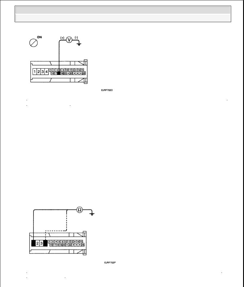
CHECK THE POWER SOURCE CIRCUIT.
1.Disconnect the connector from the ABS control module.
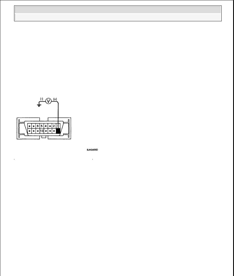
2.Turn the ignition switch ON, measure the voltage between terminal 18 of the ABS control module harness side connector and body ground.
Specification: approximately B+
Is the voltage within specification?
YES
z Check the ground circuit.
NO
zCheck the harness or connector between the fuse (10A) in the engine compartment junction block and the ABS control module. Repair if necessary.
2008 Kia Sedona
2008 BRAKES ABS (Anti-Lock Brake System) - Sedona
Fig. 13: Checking Harness Or Connector Between Fuse Engine Compartment Junction Block And ABS Control Module
Courtesy of KIA MOTORS AMERICA, INC.
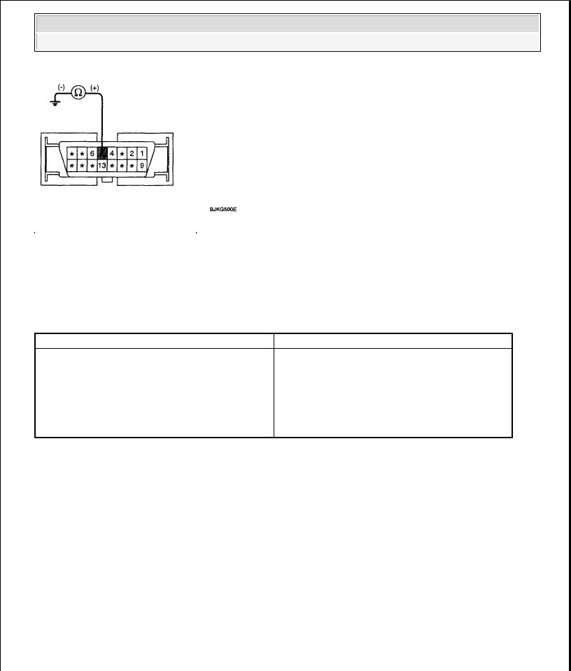
CHECK THE GROUND CIRCUIT.
1.Disconnect the connector from the ABS control module.
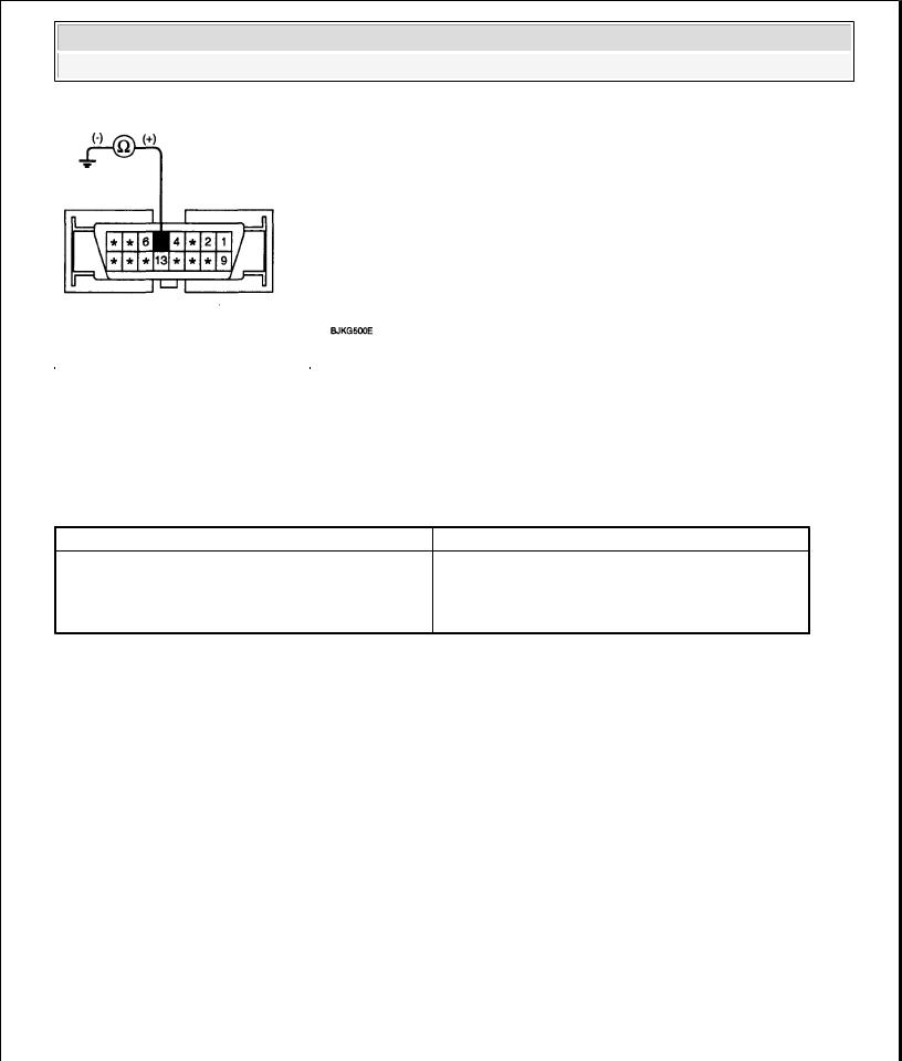
2.Check for continuity between terminals 1,4 of the ABS control module harness side connector and ground point.
Is there continuity?
YES
z Check the wheel speed sensor circuit.
NO
z Repair an open in the wire and ground point.
Fig. 14: Checking Continuity Between Terminals ABS Control Module Harness Side Connector And Ground Point
Courtesy of KIA MOTORS AMERICA, INC.
2008 Kia Sedona
2008 BRAKES ABS (Anti-Lock Brake System) - Sedona
CHECK THE WHEEL SPEED SENSOR CIRCUIT.
Refer to the DTC troubleshooting procedures .
Is the system operating to specifications?
YES
z Check the hydraulic circuit for leakage.
NO
z Repair or replace the wheel speed sensor.
CHECK THE HYDRAULIC CIRCUIT FOR LEAKAGE.
Refer to the hydraulic lines .
Inspect leakage of the hydraulic lines.
Is the system operating to specifications?
YES
z The problem is still occurring, replace the ABS control module.
NO
z Replace the leaking hydraulic lines.
ABS DOES NOT OPERATE (INTERMITTENTLY)
DETECTING CONDITION
DETECTING CONDITION CHART Trouble Symptoms
Brake operation varies depending on driving conditions and road surface conditions, so diagnosis can be difficult. However if a normal DTC is displayed, check the following probable cause. When the problem is still occurring, replace the ABS control module.
Possible Cause
{Inoperative power source circuit
{Inoperative wheel speed sensor circuit
{Inoperative hydraulic circuit for leakage
{Inoperative HECU
INSPECTION PROCEDURES
DTC INSPECTION

2008 Kia Sedona
2008 BRAKES ABS (Anti-Lock Brake System) - Sedona
1.Connect the Scan Tool with the data link connector and turn the ignition switch ON.
2.Verify that the system is operating to specifications. Is the system operating to specifications?
NO
z Check the wheel speed sensor circuit.
YES
z Erase the DTC and recheck using Scan Tool.
CHECK THE WHEEL SPEED SENSOR CIRCUIT.
Refer to the DTC troubleshooting procedures .
Is the system operating to specifications?
YES
z Check the stop lamp switch circuit.
NO
z Repair or replace the wheel speed sensor.
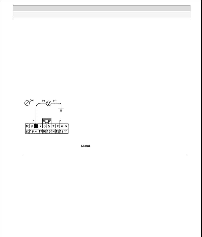
CHECK THE STOP LAMP SWITCH CIRCUIT.
1.Check that stop lamp lights up when brake pedal is depressed and turns off when brake pedal is released.
2.Measure the voltage between terminal 20 of the ABS control module harness side connector and body ground when brake pedal is depressed.
Specification: approximately B+
Is the voltage within specification?
YES
z Check the hydraulic circuit for leakage.
NO
zRepair the stop lamp switch. Repair an open in the wire between the ABS control module and the stop lamp switch.
2008 Kia Sedona
2008 BRAKES ABS (Anti-Lock Brake System) - Sedona
Fig. 15: Checking Stop Lamp Switch Circuit
Courtesy of KIA MOTORS AMERICA, INC.
CHECK THE HYDRAULIC CIRCUIT FOR LEAKAGE.
Refer to the hydraulic lines .
Inspect leakage of the hydraulic lines.
Is the system operating to specifications?
YES
z The problem is still occurring, replace the ABS control module.
NO
z Replace the leaking hydraulic lines.
COMMUNICATION WITH SCAN TOOL IS NOT POSSIBLE (COMMUNICATION WITH ANY SYSTEM IS NOT POSSIBLE)
DETECTING CONDITION
DETECTING CONDITION CHART Trouble Symptoms
Possible malfunction in the power supply system (including ground) for the diagnosis line.
INSPECTION PROCEDURES
Possible Cause
{An open in the wire
{Poor ground
{Inoperative power source circuit
CHECK THE POWER SUPPLY CIRCUIT FOR THE DIAGNOSIS
Measure the voltage between terminal 9 of the data link connector and body ground.
2008 Kia Sedona
2008 BRAKES ABS (Anti-Lock Brake System) - Sedona
Specification: approximately B+
Is voltage within specification?
YES
z Check the ground circuit for the diagnosis.
NO
z Repair an open in the wire. Check and replace fuse (15A) from the engine compartment junction block.
Fig. 16: Checking Power Supply Circuit
Courtesy of KIA MOTORS AMERICA, INC.
CHECK THE GROUND CIRCUIT FOR THE DIAGNOSIS
Check for continuity between terminal 5 of the data link connector and body ground. Is there continuity?
NO
z Repair an open in the wire between terminal 5 of the data link connector and ground point.
2008 Kia Sedona
2008 BRAKES ABS (Anti-Lock Brake System) - Sedona
Fig. 17: Checking Ground Circuit
Courtesy of KIA MOTORS AMERICA, INC.
COMMUNICATION WITH SCAN TOOL IS NOT POSSIBLE (COMMUNICATION WITH ABS ONLY IS NOT POSSIBLE)
DETECTING CONDITION
DETECTING CONDITION CHART Trouble Symptoms
When communication with Scan Tool is not possible, the cause may be probably an open in the HECU power circuit or an open in the diagnosis output circuit.
INSPECTION PROCEDURES
CHECK FOR CONTINUITY IN THE DIAGNOSIS LINE
Possible Cause
{An open in the wire
{Inoperative HECU
{Inoperative power source circuit
1.Disconnect the connector from the ABS control module.
2.Check for continuity between terminals 11 of the ABS control module connector and 1 of the data link connector.
Is there continuity?
YES
z Check the power source of ABS control module.
NO
z Repair an open in the wire.
CHECK THE POWER SOURCE OF ABS CONTROL MODULE
2008 Kia Sedona
2008 BRAKES ABS (Anti-Lock Brake System) - Sedona
1.Disconnect the connector from the ABS control module.
2.Turn the ignition switch ON, measure the voltage between terminal 18 of the ABS control module harness side connector and body ground.
Specification: approximately B+ Is voltage within specification?
YES
z Check for poor ground.
NO
zCheck the harness or connector between the fuse (10A) in the engine compartment junction block and the ABS control module. Repair if necessary.
Fig. 18: Checking Harness Or Connector Between Fuse Engine Compartment Junction Block And ABS Control Module
Courtesy of KIA MOTORS AMERICA, INC.
CHECK FOR POOR GROUND
Check for continuity between terminal 5 of the data link connector and ground point.
YES
z Replace the ABS control module and recheck.
NO
z Repair an open in the wire or poor ground.
2008 Kia Sedona
2008 BRAKES ABS (Anti-Lock Brake System) - Sedona
Fig. 19: Checking Ground Circuit
Courtesy of KIA MOTORS AMERICA, INC.
WHEN IGNITION KEY IS TURNED ON (ENGINE OFF), THE ABS WARNING LAMP DOES NOT LIGHT UP
DETECTING CONDITION
DETECTING CONDITION CHART Trouble Symptoms
When current flows in the HECU the ABS warning lamp turns from ON to OFF as the initial check. Therefore if the lamp does not light up, the cause may be an open in the lamp power supply circuit, a blown bulb, an open in the both circuits between the ABS warning lamp and the HECU, and the inoperative HECU.
INSPECTION PROCEDURES
PROBLEM VERIFICATION
Possible Cause
{Inoperative ABS warning lamp bulb
{Blown No.2 fuse (10A) in the engine compartment junction block
{Inoperative ABS warning lamp module
{Inoperative HECU
Disconnect the connector from the ABS control module and turn the ignition switch ON.
Does the ABS warning lamp light up?
YES
z It is normal. Recheck the ABS control module.
NO
z Check the power source for the ABS warning lamp.
CHECK THE POWER SOURCE FOR THE ABS WARNING LAMP
2008 Kia Sedona
2008 BRAKES ABS (Anti-Lock Brake System) - Sedona
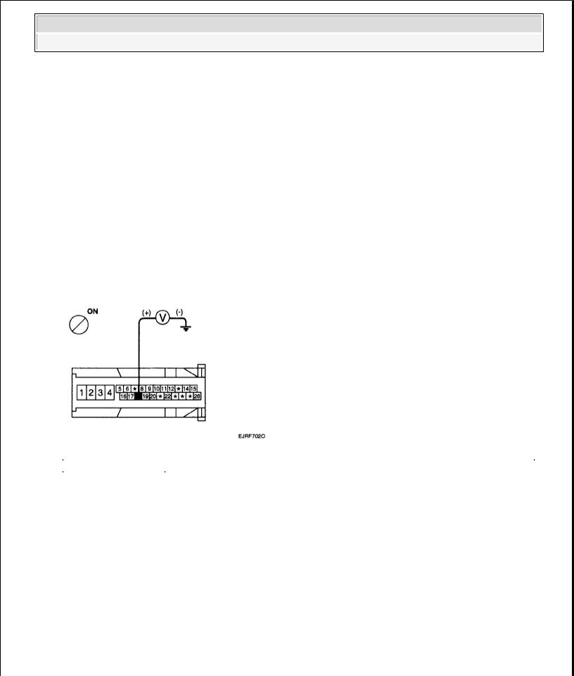
1.Disconnect the instrument cluster connector and turn the ignition switch ON.
2.Measure the voltage between terminal 8 of the cluster harness side connector and body ground. Specification: approximately B+
Is voltage within specification?
YES
z Repair bulb or instrument cluster assembly.
NO
z Check for blown fuse.
Fig. 20: Measuring Voltage Between Terminal Cluster Harness Side Connector And Body Ground Courtesy of KIA MOTORS AMERICA, INC.
CHECK FOR BLOWN FUSE
Check continuity of fuse (10A) from the engine compartment junction block.
Is there continuity?
YES
z Repair an open in the wire between ABS fuse and 1 of cluster connector.
NO
z Replace the blown fuse.
EVEN AFTER THE ENGINE IS STARTED, THE ABS WARNING LAMP REMAINS ON
2008 Kia Sedona
2008 BRAKES ABS (Anti-Lock Brake System) - Sedona
DETECTING CONDITION
DETECTING CONDITION CHART Trouble Symptoms
If the HECU detects trouble, it lights the ABS warning lamp while at the same time prohibiting ABS control. At this time, the HECU records a DTC in memory. Even though the normal code is output, the ABS warning lamp remains ON, then the cause may be probably an open or short in the ABS warning lamp circuit.
INSPECTION PROCEDURES
CHECK DTC OUTPUT.
Possible Cause
{An open in the wire
{Inoperative instrument cluster assembly
{Inoperative ABS warning lamp module
{Inoperative HECU
1.Connect the Scan Tool (pro) to the 16P data link connector located behind the driver's side kick panel.
2.Check the DTC output using Scan Tool (pro). Is DTC output?
YES
z Repair circuit indicated by code output.
NO
z Check instrument cluster.
CHECK INSTRUMENT CLUSTER
Disconnect the cluster connector and turn the ignition switch ON.
Does the ABS warning lamp remains ON?
YES
z Replace the instrument cluster.
NO
z Check for open the wire.
CHECK FOR OPEN IN THE WIRE
Check for continuity in the wire between cluster and ABS control module.
2008 Kia Sedona
2008 BRAKES ABS (Anti-Lock Brake System) - Sedona
Is there continuity?
YES
z Replace the ABS control module and recheck.
NO
z Repair an open in the wire between cluster and ABS control module.
BLEEDING OF BRAKE SYSTEM
This procedure should be followed to ensure adequate bleeding of air and filling of the ABS unit, brake lines and master cylinder with brake fluid.
1. Remove the reservoir cap and fill the brake reservoir with brake fluid.
CAUTION: If there is any brake fluid on any painted surface, wash it off immediately.
NOTE: |
When pressure bleeding, do not depress the brake pedal. |
|
|
Recommended fluid....... |
DOT3 or DOT4 |
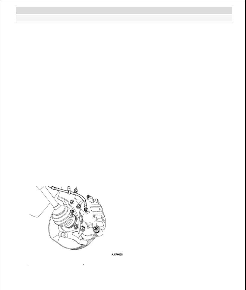
2.Connect a clear plastic tube to the brake caliper bleeder plug and insert the other end of the tube into a half filled clear plastic bottle.
Fig. 21: Identifying Caliper
Courtesy of KIA MOTORS AMERICA, INC.
3. Connect the scan tool to the data link connector located underneath the dash panel.
2008 Kia Sedona
2008 BRAKES ABS (Anti-Lock Brake System) - Sedona
Fig. 22: Connecting Scan Tool To Data Link Connector
Courtesy of KIA MOTORS AMERICA, INC.
4. Select and operate according to the instructions on the scan tool screen.
CAUTION: You must obey the maximum operating time of the ABS motor with the scan tool to prevent the motor pump from burning.
1.Select Kia vehicle diagnosis.
2.Select vehicle name.
3.Select Anti-Lock Brake system.
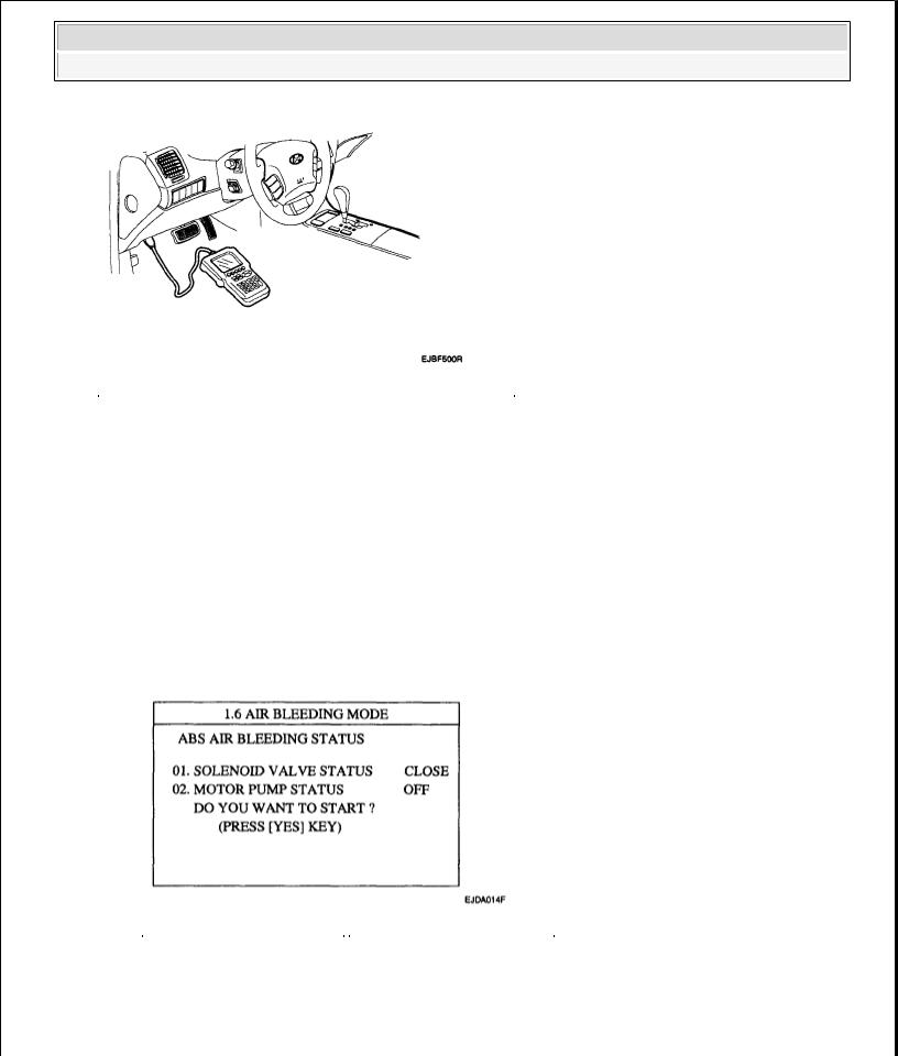
4.Select air bleeding mode.
5.Press "YES" to operate motor pump and solenoid valve.
Fig. 23: Scan Tool Display - Air Bleeding Mode (Close)
Courtesy of KIA MOTORS AMERICA, INC.
6. Wait 60 sec. before operating the air bleeding again. (If not, you may damage the motor.)
2008 Kia Sedona
2008 BRAKES ABS (Anti-Lock Brake System) - Sedona
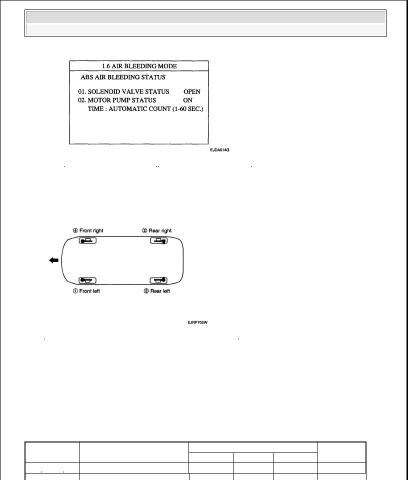
Fig. 24: Scan Tool Display - Air Bleeding Mode (Open)
Courtesy of KIA MOTORS AMERICA, INC.
5.Pump the brake pedal several times, and then loosen the bleeder screw until fluid starts to run out without bubbles. Then close the bleeder screw.
6.Repeat step 5 until there are no more bubbles in the fluid for each wheel.
Fig. 25: Identifying Bleeder Screws & Bleeding Sequence
Courtesy of KIA MOTORS AMERICA, INC.
7.Tighten the bleeder screw. Bleed screw tightening torque:
7-1 3 Nm (0.7 -1.3 kgf.m, 5.06 - 9.4 lb-ft)
DIAGNOSTIC TROUBLE CODE CHART (DTC)
DIAGNOSTIC TROUBLE CODE CHART |
|
WARNING LAMP |
|
|
||
DTC |
DESCRIPTION |
|
|
REMARK |
||
ABS |
EBD |
ESC |
||||
C1101 |
|
|
||||
BATTERY VOLTAGE HIGH |
o |
o |
o |
|
||
 Loading...