

Page 1
Service and Maintenance Manual
Model
510AJ
P/N - 3121181
August, 2014
Page 2

Page 3

INTRODUCTION
SECTION A. INTRODUCTION - MAINTENANCE SAFETY PRECAUTIONS
AGENERAL
This section contains the general safety precautions which
must be observed during maintenance of the aerial platform.
It is of utmost importance that maintenance personnel pay
strict attention to these warnings and precautions to avoid
possible injury to themselves or others, or damage to the
equipment. A maintenance program must be followed to
ensure that the machine is safe to operate.
MODIFICATION OR ALTERATION OF AN AERIAL WORK PLATFORM SHALL BE
MADE ONLY WITH WRITTEN PERMISSION FROM THE MANUFACTURER.
The specific precautions to be observed during maintenance
are inserted at the appropriate point in the manual. These precautions are, for the most part, those that apply when servicing hydraulic and larger machine component parts.
Your safety, and that of others, is the first consideration when
engaging in the maintenance of equipment. Always be conscious of weight. Never attempt to move heavy parts without
the aid of a mechanical device. Do not allow heavy objects to
rest in an unstable position. When raising a portion of the
equipment, ensure that adequate support is provided.
SINCE THE MACHINE MANUFACTURER HAS NO DIRECT CONTROL OVER THE
FIELD INSPECTION AND MAINTENANCE, SAFETY IN THIS AREA RESPONSIBILITY OF THE OWNER/OPERATOR.
BHYDRAULIC SYSTEM SAFETY
It should be noted that the machines hydraulic systems operate at extremely high potentially dangerous pressures. Every
effort should be made to relieve any system pressure prior to
disconnecting or removing any portion of the system.
Relieve system pressure by cycling applicable control several
times with the engine stopped and ignition on, to direct any
line pressure back into the reservoir. Pressure feed lines to system components can then be disconnected with minimal fluid
loss.
CMAINTENANCE
FAILURE TO COMPLY WITH SAFETY PRECAUTIONS LISTED IN THIS SECTION
COULD RESULT IN MACHINE DAMAGE, PERSONNEL INJURY OR DEATH AND IS A
SAFETY VIOLATION.
• ENSURE REPLACEMENT PARTS OR COMPONENTS ARE
IDENTICAL OR EQUIVALENT TO ORIGINAL PARTS OR
COMPONENTS.
• NO SMOKING IS MANDATORY. NEVER REFUEL DURING ELECTRICAL STORMS. ENSURE THAT FUEL CAP IS CLOSED AND
SECURE AT ALL OTHER TIMES.
• REMOVE ALL RINGS, WATCHES AND JEWELRY WHEN PERFORMING ANY MAINTENANCE.
• DO NOT WEAR LONG HAIR UNRESTRAINED, OR LOOSE-FITTING CLOTHING AND NECKTIES WHICH ARE APT TO BECOME
CAUGHT ON OR ENTANGLED IN EQUIPMENT.
• OBSERVE AND OBEY ALL WARNINGS AND CAUTIONS ON
MACHINE AND IN SERVICE MANUAL.
• KEEP OIL, GREASE, WATER, ETC. WIPED FROM STANDING
SURFACES AND HAND HOLDS.
• USE CAUTION WHEN CHECKING A HOT, PRESSURIZED COOLANT SYSTEM.
• NEVER WORK UNDER AN ELEVATED BOOM UNTIL BOOM HAS
BEEN SAFELY RESTRAINED FROM ANY MOVEMENT BY
BLOCKING OR OVERHEAD SLING, OR BOOM SAFETY PROP
HAS BEEN ENGAGED.
• BEFORE MAKING ADJUSTMENTS, LUBRICATING OR PERFORMING ANY OTHER MAINTENANCE, SHUT OFF ALL
POWER CONTROLS.
• BATTERY SHOULD ALWAYS BE DISCONNECTEDDURING
REPLACEMENT OF ELECTRICAL COMPONENTS.
• KEEP ALL SUPPORT EQUIPMENT AND ATTACHMENTS
STOWED IN THEIR PROPER PLACE.
• USE ONLY APPROVED, NONFLAMMABLE CLEANING SOLVENTS.
3121181 – JLG Lift – A-1
Page 4

INTRODUCTION
REVISON LOG
Original Issue - January 24, 2003
Revised - March 12, 2003
Revised - September 20, 2005
Revised - March 16, 2007
Revised - October 10, 2007
Revised - January 5, 2011
Revised - August 20, 2014
A-2 – JLG Lift – 3121181
Page 5

TABLE OF CONTENTS
SECTION NO. TITLE PAGE NO.
SECTION A - INTRODUCTION - MAINTENANCE SAFETY PRECAUTIONS
A General . . . . . . . . . . . . . . . . . . . . . . . . . . . . . . . . . . . . . . . . . . . . . . . . . . . . . . . . . . . . . . . . . . . . . . . . . . . . . . . . . . . . . . . . . . . . A-1
B Hydraulic System Safety . . . . . . . . . . . . . . . . . . . . . . . . . . . . . . . . . . . . . . . . . . . . . . . . . . . . . . . . . . . . . . . . . . . . . . . . . . . . A-1
C Maintenance. . . . . . . . . . . . . . . . . . . . . . . . . . . . . . . . . . . . . . . . . . . . . . . . . . . . . . . . . . . . . . . . . . . . . . . . . . . . . . . . . . . . . . . A-1
SECTION 1 - SPECIFICATIONS
1.1 Capacities . . . . . . . . . . . . . . . . . . . . . . . . . . . . . . . . . . . . . . . . . . . . . . . . . . . . . . . . . . . . . . . . . . . . . . . . . . . . . . . . . . . . . . . . . 1-1
1.2 Tires . . . . . . . . . . . . . . . . . . . . . . . . . . . . . . . . . . . . . . . . . . . . . . . . . . . . . . . . . . . . . . . . . . . . . . . . . . . . . . . . . . . . . . . . . . . . . . . 1-1
1.3 Engine. . . . . . . . . . . . . . . . . . . . . . . . . . . . . . . . . . . . . . . . . . . . . . . . . . . . . . . . . . . . . . . . . . . . . . . . . . . . . . . . . . . . . . . . . . . . . 1-1
1.4 Specifications and Performance Data . . . . . . . . . . . . . . . . . . . . . . . . . . . . . . . . . . . . . . . . . . . . . . . . . . . . . . . . . . . . . . . 1-1
Dimensional Data . . . . . . . . . . . . . . . . . . . . . . . . . . . . . . . . . . . . . . . . . . . . . . . . . . . . . . . . . . . . . . . . . . . . . . . . . . . . . 1-1
Reach Specifications . . . . . . . . . . . . . . . . . . . . . . . . . . . . . . . . . . . . . . . . . . . . . . . . . . . . . . . . . . . . . . . . . . . . . . . . . . 1-2
Chassis . . . . . . . . . . . . . . . . . . . . . . . . . . . . . . . . . . . . . . . . . . . . . . . . . . . . . . . . . . . . . . . . . . . . . . . . . . . . . . . . . . . . . . . 1-2
1.5 Function Speeds . . . . . . . . . . . . . . . . . . . . . . . . . . . . . . . . . . . . . . . . . . . . . . . . . . . . . . . . . . . . . . . . . . . . . . . . . . . . . . . . . . . 1-2
Machine Orientation When Doing Speed Tests . . . . . . . . . . . . . . . . . . . . . . . . . . . . . . . . . . . . . . . . . . . . . . . . . 1-2
Test Notes . . . . . . . . . . . . . . . . . . . . . . . . . . . . . . . . . . . . . . . . . . . . . . . . . . . . . . . . . . . . . . . . . . . . . . . . . . . . . . . . . . . . 1-2
1.6 Torque Requirements . . . . . . . . . . . . . . . . . . . . . . . . . . . . . . . . . . . . . . . . . . . . . . . . . . . . . . . . . . . . . . . . . . . . . . . . . . . . . . 1-3
1.7 Lubrication . . . . . . . . . . . . . . . . . . . . . . . . . . . . . . . . . . . . . . . . . . . . . . . . . . . . . . . . . . . . . . . . . . . . . . . . . . . . . . . . . . . . . . . . 1-3
Hydraulic Oil . . . . . . . . . . . . . . . . . . . . . . . . . . . . . . . . . . . . . . . . . . . . . . . . . . . . . . . . . . . . . . . . . . . . . . . . . . . . . . . . . . 1-3
1.8 Operator Maintenance . . . . . . . . . . . . . . . . . . . . . . . . . . . . . . . . . . . . . . . . . . . . . . . . . . . . . . . . . . . . . . . . . . . . . . . . . . . . . 1-5
1.9 Major Component Weights. . . . . . . . . . . . . . . . . . . . . . . . . . . . . . . . . . . . . . . . . . . . . . . . . . . . . . . . . . . . . . . . . . . . . . . . . 1-8
1.10 Pressure Settings. . . . . . . . . . . . . . . . . . . . . . . . . . . . . . . . . . . . . . . . . . . . . . . . . . . . . . . . . . . . . . . . . . . . . . . . . . . . . . . . . . . 1-8
1.11 Serial Number Location . . . . . . . . . . . . . . . . . . . . . . . . . . . . . . . . . . . . . . . . . . . . . . . . . . . . . . . . . . . . . . . . . . . . . . . . . . . . 1-8
SECTION 2 - GENERAL
2.1 Machine Preparation, Inspection, and Maintenance . . . . . . . . . . . . . . . . . . . . . . . . . . . . . . . . . . . . . . . . . . . . . . . . . 2-1
General . . . . . . . . . . . . . . . . . . . . . . . . . . . . . . . . . . . . . . . . . . . . . . . . . . . . . . . . . . . . . . . . . . . . . . . . . . . . . . . . . . . . . . . 2-1
Preparation, Inspection, and Maintenance . . . . . . . . . . . . . . . . . . . . . . . . . . . . . . . . . . . . . . . . . . . . . . . . . . . . . 2-1
Pre-Start Inspection . . . . . . . . . . . . . . . . . . . . . . . . . . . . . . . . . . . . . . . . . . . . . . . . . . . . . . . . . . . . . . . . . . . . . . . . . . . 2-1
Pre-Delivery Inspection and Frequent Inspection. . . . . . . . . . . . . . . . . . . . . . . . . . . . . . . . . . . . . . . . . . . . . . . 2-1
Annual Machine Inspection. . . . . . . . . . . . . . . . . . . . . . . . . . . . . . . . . . . . . . . . . . . . . . . . . . . . . . . . . . . . . . . . . . . . 2-1
Preventative Maintenance. . . . . . . . . . . . . . . . . . . . . . . . . . . . . . . . . . . . . . . . . . . . . . . . . . . . . . . . . . . . . . . . . . . . . 2-1
2.2 Service and Guidelines . . . . . . . . . . . . . . . . . . . . . . . . . . . . . . . . . . . . . . . . . . . . . . . . . . . . . . . . . . . . . . . . . . . . . . . . . . . . . 2-2
General . . . . . . . . . . . . . . . . . . . . . . . . . . . . . . . . . . . . . . . . . . . . . . . . . . . . . . . . . . . . . . . . . . . . . . . . . . . . . . . . . . . . . . . 2-2
Safety and Workmanship . . . . . . . . . . . . . . . . . . . . . . . . . . . . . . . . . . . . . . . . . . . . . . . . . . . . . . . . . . . . . . . . . . . . . . 2-2
Cleanliness. . . . . . . . . . . . . . . . . . . . . . . . . . . . . . . . . . . . . . . . . . . . . . . . . . . . . . . . . . . . . . . . . . . . . . . . . . . . . . . . . . . . 2-2
Components Removal and Installation. . . . . . . . . . . . . . . . . . . . . . . . . . . . . . . . . . . . . . . . . . . . . . . . . . . . . . . . . 2-2
Component Disassembly and Reassembly . . . . . . . . . . . . . . . . . . . . . . . . . . . . . . . . . . . . . . . . . . . . . . . . . . . . . 2-2
Pressure-Fit Parts. . . . . . . . . . . . . . . . . . . . . . . . . . . . . . . . . . . . . . . . . . . . . . . . . . . . . . . . . . . . . . . . . . . . . . . . . . . . . . 2-3
Bearings . . . . . . . . . . . . . . . . . . . . . . . . . . . . . . . . . . . . . . . . . . . . . . . . . . . . . . . . . . . . . . . . . . . . . . . . . . . . . . . . . . . . . . 2-3
Gaskets . . . . . . . . . . . . . . . . . . . . . . . . . . . . . . . . . . . . . . . . . . . . . . . . . . . . . . . . . . . . . . . . . . . . . . . . . . . . . . . . . . . . . . . 2-3
Bolt Usage and Torque Application . . . . . . . . . . . . . . . . . . . . . . . . . . . . . . . . . . . . . . . . . . . . . . . . . . . . . . . . . . . . 2-3
Hydraulic Lines and Electrical Wiring. . . . . . . . . . . . . . . . . . . . . . . . . . . . . . . . . . . . . . . . . . . . . . . . . . . . . . . . . . . 2-3
Hydraulic System. . . . . . . . . . . . . . . . . . . . . . . . . . . . . . . . . . . . . . . . . . . . . . . . . . . . . . . . . . . . . . . . . . . . . . . . . . . . . . 2-3
Lubrication . . . . . . . . . . . . . . . . . . . . . . . . . . . . . . . . . . . . . . . . . . . . . . . . . . . . . . . . . . . . . . . . . . . . . . . . . . . . . . . . . . . 2-3
Battery. . . . . . . . . . . . . . . . . . . . . . . . . . . . . . . . . . . . . . . . . . . . . . . . . . . . . . . . . . . . . . . . . . . . . . . . . . . . . . . . . . . . . . . . 2-3
Lubrication and Servicing . . . . . . . . . . . . . . . . . . . . . . . . . . . . . . . . . . . . . . . . . . . . . . . . . . . . . . . . . . . . . . . . . . . . . 2-3
2.3 Lubrication and Information. . . . . . . . . . . . . . . . . . . . . . . . . . . . . . . . . . . . . . . . . . . . . . . . . . . . . . . . . . . . . . . . . . . . . . . . 2-3
Hydraulic System. . . . . . . . . . . . . . . . . . . . . . . . . . . . . . . . . . . . . . . . . . . . . . . . . . . . . . . . . . . . . . . . . . . . . . . . . . . . . . 2-3
Hydraulic Oil . . . . . . . . . . . . . . . . . . . . . . . . . . . . . . . . . . . . . . . . . . . . . . . . . . . . . . . . . . . . . . . . . . . . . . . . . . . . . . . . . . 2-4
Changing Hydraulic Oil. . . . . . . . . . . . . . . . . . . . . . . . . . . . . . . . . . . . . . . . . . . . . . . . . . . . . . . . . . . . . . . . . . . . . . . . 2-4
Lubrication Specifications . . . . . . . . . . . . . . . . . . . . . . . . . . . . . . . . . . . . . . . . . . . . . . . . . . . . . . . . . . . . . . . . . . . . . 2-4
Cylinder Drift Test . . . . . . . . . . . . . . . . . . . . . . . . . . . . . . . . . . . . . . . . . . . . . . . . . . . . . . . . . . . . . . . . . . . . . . . . . . . . . 2-4
Platform Drift . . . . . . . . . . . . . . . . . . . . . . . . . . . . . . . . . . . . . . . . . . . . . . . . . . . . . . . . . . . . . . . . . . . . . . . . . . . . . . . . . 2-4
Cylinder Drift. . . . . . . . . . . . . . . . . . . . . . . . . . . . . . . . . . . . . . . . . . . . . . . . . . . . . . . . . . . . . . . . . . . . . . . . . . . . . . . . . . 2-4
2.4 Pins and Composite Bearing Repair Guidelines . . . . . . . . . . . . . . . . . . . . . . . . . . . . . . . . . . . . . . . . . . . . . . . . . . . . . . 2-5
2.5 Welding on JLG Equipment. . . . . . . . . . . . . . . . . . . . . . . . . . . . . . . . . . . . . . . . . . . . . . . . . . . . . . . . . . . . . . . . . . . . . . . . . 2-5
3121181 – JLG Lift – i
Page 6

TABLE OF CONTENTS
SECTION NO. TITLE PAGE NO.
SECTION 3 - CHASSIS AND TURNTABLE
3.1 Tires & Wheels. . . . . . . . . . . . . . . . . . . . . . . . . . . . . . . . . . . . . . . . . . . . . . . . . . . . . . . . . . . . . . . . . . . . . . . . . . . . . . . . . . . . . . 3-1
Tire Inflation. . . . . . . . . . . . . . . . . . . . . . . . . . . . . . . . . . . . . . . . . . . . . . . . . . . . . . . . . . . . . . . . . . . . . . . . . . . . . . . . . . 3-1
Tire Damage . . . . . . . . . . . . . . . . . . . . . . . . . . . . . . . . . . . . . . . . . . . . . . . . . . . . . . . . . . . . . . . . . . . . . . . . . . . . . . . . . 3-1
Tire Replacement. . . . . . . . . . . . . . . . . . . . . . . . . . . . . . . . . . . . . . . . . . . . . . . . . . . . . . . . . . . . . . . . . . . . . . . . . . . . . 3-1
Wheel Replacement . . . . . . . . . . . . . . . . . . . . . . . . . . . . . . . . . . . . . . . . . . . . . . . . . . . . . . . . . . . . . . . . . . . . . . . . . . 3-1
Wheel Installation . . . . . . . . . . . . . . . . . . . . . . . . . . . . . . . . . . . . . . . . . . . . . . . . . . . . . . . . . . . . . . . . . . . . . . . . . . . . 3-1
3.2 Torque Hub (Machines built Before S/N 1300000064) . . . . . . . . . . . . . . . . . . . . . . . . . . . . . . . . . . . . . . . . . . . . . . . . 3-2
Roll, Leak and Brake Testing. . . . . . . . . . . . . . . . . . . . . . . . . . . . . . . . . . . . . . . . . . . . . . . . . . . . . . . . . . . . . . . . . . . 3-2
Tightening and Torquing Bolts. . . . . . . . . . . . . . . . . . . . . . . . . . . . . . . . . . . . . . . . . . . . . . . . . . . . . . . . . . . . . . . . 3-2
Main Disassembly . . . . . . . . . . . . . . . . . . . . . . . . . . . . . . . . . . . . . . . . . . . . . . . . . . . . . . . . . . . . . . . . . . . . . . . . . . . . 3-3
Input Carrier Disassembly. . . . . . . . . . . . . . . . . . . . . . . . . . . . . . . . . . . . . . . . . . . . . . . . . . . . . . . . . . . . . . . . . . . . . 3-5
Output Carrier Disassembly . . . . . . . . . . . . . . . . . . . . . . . . . . . . . . . . . . . . . . . . . . . . . . . . . . . . . . . . . . . . . . . . . . . 3-6
Housing-Spindle Disassembly. . . . . . . . . . . . . . . . . . . . . . . . . . . . . . . . . . . . . . . . . . . . . . . . . . . . . . . . . . . . . . . . . 3-7
Spindle-Brake Disassembly . . . . . . . . . . . . . . . . . . . . . . . . . . . . . . . . . . . . . . . . . . . . . . . . . . . . . . . . . . . . . . . . . . . 3-8
Input Carrier Sub-Assembly . . . . . . . . . . . . . . . . . . . . . . . . . . . . . . . . . . . . . . . . . . . . . . . . . . . . . . . . . . . . . . . . . . . 3-9
Output Carrier Sub-Assembly . . . . . . . . . . . . . . . . . . . . . . . . . . . . . . . . . . . . . . . . . . . . . . . . . . . . . . . . . . . . . . . . . 3-11
Spindle-Brake Sub-Assembly. . . . . . . . . . . . . . . . . . . . . . . . . . . . . . . . . . . . . . . . . . . . . . . . . . . . . . . . . . . . . . . . . . 3-13
Housing-Spindle Sub-Assembly. . . . . . . . . . . . . . . . . . . . . . . . . . . . . . . . . . . . . . . . . . . . . . . . . . . . . . . . . . . . . . . 3-15
Integral Brake Check. . . . . . . . . . . . . . . . . . . . . . . . . . . . . . . . . . . . . . . . . . . . . . . . . . . . . . . . . . . . . . . . . . . . . . . . . . 3-15
Main Assembly . . . . . . . . . . . . . . . . . . . . . . . . . . . . . . . . . . . . . . . . . . . . . . . . . . . . . . . . . . . . . . . . . . . . . . . . . . . . . . . 3-17
3.3 Torque Hub (Machines built After S/N 1300000064) . . . . . . . . . . . . . . . . . . . . . . . . . . . . . . . . . . . . . . . . . . . . . . . . . 3-29
Roll and Leak Testing . . . . . . . . . . . . . . . . . . . . . . . . . . . . . . . . . . . . . . . . . . . . . . . . . . . . . . . . . . . . . . . . . . . . . . . . . 3-29
Tightening and Torquing Bolts . . . . . . . . . . . . . . . . . . . . . . . . . . . . . . . . . . . . . . . . . . . . . . . . . . . . . . . . . . . . . . . 3-29
Oil Information . . . . . . . . . . . . . . . . . . . . . . . . . . . . . . . . . . . . . . . . . . . . . . . . . . . . . . . . . . . . . . . . . . . . . . . . . . . . . . . 3-29
Main Disassembly for ”B” Drives . . . . . . . . . . . . . . . . . . . . . . . . . . . . . . . . . . . . . . . . . . . . . . . . . . . . . . . . . . . . . . 3-29
Hub-Spindle Disassembly . . . . . . . . . . . . . . . . . . . . . . . . . . . . . . . . . . . . . . . . . . . . . . . . . . . . . . . . . . . . . . . . . . . . 3-30
Cover Disassembly . . . . . . . . . . . . . . . . . . . . . . . . . . . . . . . . . . . . . . . . . . . . . . . . . . . . . . . . . . . . . . . . . . . . . . . . . . . 3-30
Carrier Disassembly. . . . . . . . . . . . . . . . . . . . . . . . . . . . . . . . . . . . . . . . . . . . . . . . . . . . . . . . . . . . . . . . . . . . . . . . . . . 3-30
Carrier Assembly . . . . . . . . . . . . . . . . . . . . . . . . . . . . . . . . . . . . . . . . . . . . . . . . . . . . . . . . . . . . . . . . . . . . . . . . . . . . . 3-31
Cover Sub-Assembly. . . . . . . . . . . . . . . . . . . . . . . . . . . . . . . . . . . . . . . . . . . . . . . . . . . . . . . . . . . . . . . . . . . . . . . . . . 3-33
Hub-Spindle Sub-Assembly . . . . . . . . . . . . . . . . . . . . . . . . . . . . . . . . . . . . . . . . . . . . . . . . . . . . . . . . . . . . . . . . . . . 3-34
Main Assembly . . . . . . . . . . . . . . . . . . . . . . . . . . . . . . . . . . . . . . . . . . . . . . . . . . . . . . . . . . . . . . . . . . . . . . . . . . . . . . . 3-36
Tool List . . . . . . . . . . . . . . . . . . . . . . . . . . . . . . . . . . . . . . . . . . . . . . . . . . . . . . . . . . . . . . . . . . . . . . . . . . . . . . . . . . . . . 3-41
3.4 Re-Aligning torque hub input coupling . . . . . . . . . . . . . . . . . . . . . . . . . . . . . . . . . . . . . . . . . . . . . . . . . . . . . . . . . . . . . 3-42
Equipment Required . . . . . . . . . . . . . . . . . . . . . . . . . . . . . . . . . . . . . . . . . . . . . . . . . . . . . . . . . . . . . . . . . . . . . . . . . 3-42
Procedure. . . . . . . . . . . . . . . . . . . . . . . . . . . . . . . . . . . . . . . . . . . . . . . . . . . . . . . . . . . . . . . . . . . . . . . . . . . . . . . . . . . . 3-42
3.5 Drive Motor . . . . . . . . . . . . . . . . . . . . . . . . . . . . . . . . . . . . . . . . . . . . . . . . . . . . . . . . . . . . . . . . . . . . . . . . . . . . . . . . . . . . . . . . 3-42
Description. . . . . . . . . . . . . . . . . . . . . . . . . . . . . . . . . . . . . . . . . . . . . . . . . . . . . . . . . . . . . . . . . . . . . . . . . . . . . . . . . . . 3-42
Shaft Seal Replacement. . . . . . . . . . . . . . . . . . . . . . . . . . . . . . . . . . . . . . . . . . . . . . . . . . . . . . . . . . . . . . . . . . . . . . . 3-42
Loop Flushing Valve . . . . . . . . . . . . . . . . . . . . . . . . . . . . . . . . . . . . . . . . . . . . . . . . . . . . . . . . . . . . . . . . . . . . . . . . . . 3-43
Troubleshooting . . . . . . . . . . . . . . . . . . . . . . . . . . . . . . . . . . . . . . . . . . . . . . . . . . . . . . . . . . . . . . . . . . . . . . . . . . . . . 3-44
Disassembly. . . . . . . . . . . . . . . . . . . . . . . . . . . . . . . . . . . . . . . . . . . . . . . . . . . . . . . . . . . . . . . . . . . . . . . . . . . . . . . . . . 3-45
Inspection. . . . . . . . . . . . . . . . . . . . . . . . . . . . . . . . . . . . . . . . . . . . . . . . . . . . . . . . . . . . . . . . . . . . . . . . . . . . . . . . . . . . 3-48
Assembly . . . . . . . . . . . . . . . . . . . . . . . . . . . . . . . . . . . . . . . . . . . . . . . . . . . . . . . . . . . . . . . . . . . . . . . . . . . . . . . . . . . . 3-51
Initial Start-up Procedures . . . . . . . . . . . . . . . . . . . . . . . . . . . . . . . . . . . . . . . . . . . . . . . . . . . . . . . . . . . . . . . . . . . . 3-55
3.6 Adjustment Procedure For Lockout Valve . . . . . . . . . . . . . . . . . . . . . . . . . . . . . . . . . . . . . . . . . . . . . . . . . . . . . . . . . . . 3-58
3.7 Oscillating Axle Bleeding Procedure and Lockout Test . . . . . . . . . . . . . . . . . . . . . . . . . . . . . . . . . . . . . . . . . . . . . . . 3-58
Lockout Cylinder Bleeding (Early Cylinders). . . . . . . . . . . . . . . . . . . . . . . . . . . . . . . . . . . . . . . . . . . . . . . . . . . . 3-58
Lockout Cylinder Bleeding (Ram Cylinders) . . . . . . . . . . . . . . . . . . . . . . . . . . . . . . . . . . . . . . . . . . . . . . . . . . . . 3-59
Oscillating Axle Lockout Test. . . . . . . . . . . . . . . . . . . . . . . . . . . . . . . . . . . . . . . . . . . . . . . . . . . . . . . . . . . . . . . . . . 3-59
3.8 Swing Bearing. . . . . . . . . . . . . . . . . . . . . . . . . . . . . . . . . . . . . . . . . . . . . . . . . . . . . . . .
Description. . . . . . . . . . . . . . . . . . . . . . . . . . . . . . . . . . . . . . . . . . . . . . . . . . . . . . . . . . . . . . . . . . . . . . . . . . . . . . . . . . . 3-60
Removal . . . . . . . . . . . . . . . . . . . . . . . . . . . . . . . . . . . . . . . . . . . . . . . . . . . . . . . . . . . . . . . . . . . . . . . . . . . . . . . . . . . . . 3-60
Disassembly. . . . . . . . . . . . . . . . . . . . . . . . . . . . . . . . . . . . . . . . . . . . . . . . . . . . . . . . . . . . . . . . . . . . . . . . . . . . . . . . . . 3-60
Assembly . . . . . . . . . . . . . . . . . . . . . . . . . . . . . . . . . . . . . . . . . . . . . . . . . . . . . . . . . . . . . . . . . . . . . . . . . . . . . . . . . . . . 3-63
Installation . . . . . . . . . . . . . . . . . . . . . . . . . . . . . . . . . . . . . . . . . . . . . . . . . . . . . . . . . . . . . . . . . . . . . . . . . . . . . . . . . . . 3-63
. . . . . . . . . . . . . . . . . . . . . . . . . . . . . . 3-60
ii – JLG Lift – 3121181
Page 7

TABLE OF CONTENTS
SECTION NO. TITLE PAGE NO.
Turntable Bearing Mounting Bolt Condition Check . . . . . . . . . . . . . . . . . . . . . . . . . . . . . . . . . . . . . . . . . . . . . 3-64
Wear Tolerance . . . . . . . . . . . . . . . . . . . . . . . . . . . . . . . . . . . . . . . . . . . . . . . . . . . . . . . . . . . . . . . . . . . . . . . . . . . . . . . 3-65
Swing Bearing Torque Value. . . . . . . . . . . . . . . . . . . . . . . . . . . . . . . . . . . . . . . . . . . . . . . . . . . . . . . . . . . . . . . . . . . 3-65
3.9 Generator. . . . . . . . . . . . . . . . . . . . . . . . . . . . . . . . . . . . . . . . . . . . . . . . . . . . . . . . . . . . . . . . . . . . . . . . . . . . . . . . . . . . . . . . . . 3-68
Every 250 hours . . . . . . . . . . . . . . . . . . . . . . . . . . . . . . . . . . . . . . . . . . . . . . . . . . . . . . . . . . . . . . . . . . . . . . . . . . . . . . . 3-68
Every 500 hours . . . . . . . . . . . . . . . . . . . . . . . . . . . . . . . . . . . . . . . . . . . . . . . . . . . . . . . . . . . . . . . . . . . . . . . . . . . . . . . 3-68
Overload Protection. . . . . . . . . . . . . . . . . . . . . . . . . . . . . . . . . . . . . . . . . . . . . . . . . . . . . . . . . . . . . . . . . . . . . . . . . . . 3-68
Inspecting Brushes, Replacing Brushes, and Cleaning Slip Rings. . . . . . . . . . . . . . . . . . . . . . . . . . . . . . . . . 3-68
3.10 Deutz Engine . . . . . . . . . . . . . . . . . . . . . . . . . . . . . . . . . . . . . . . . . . . . . . . . . . . . . . . . . . . . . . . . . . . . . . . . . . . . . . . . . . . . . . 3-70
Checking Oil Level . . . . . . . . . . . . . . . . . . . . . . . . . . . . . . . . . . . . . . . . . . . . . . . . . . . . . . . . . . . . . . . . . . . . . . . . . . . . 3-70
Changing Engine Oil . . . . . . . . . . . . . . . . . . . . . . . . . . . . . . . . . . . . . . . . . . . . . . . . . . . . . . . . . . . . . . . . . . . . . . . . . . 3-70
Changing the Oil Filter . . . . . . . . . . . . . . . . . . . . . . . . . . . . . . . . . . . . . . . . . . . . . . . . . . . . . . . . . . . . . . . . . . . . . . . . 3-70
Replacing Fuel Filter. . . . . . . . . . . . . . . . . . . . . . . . . . . . . . . . . . . . . . . . . . . . . . . . . . . . . . . . . . . . . . . . . . . . . . . . . . . 3-71
Cleaning Fuel Strainer . . . . . . . . . . . . . . . . . . . . . . . . . . . . . . . . . . . . . . . . . . . . . . . . . . . . . . . . . . . . . . . . . . . . . . . . . 3-71
3.11 Deutz EMR 2 (S/N 1300000981 to Present) . . . . . . . . . . . . . . . . . . . . . . . . . . . . . . . . . . . . . . . . . . . . . . . . . . . . . . . . . . 3-72
3.12 Perkins Engine General Maintenance . . . . . . . . . . . . . . . . . . . . . . . . . . . . . . . . . . . . . . . . . . . . . . . . . . . . . . . . . . . . . . . 3-84
Replacing the Engine Crankcase Breather . . . . . . . . . . . . . . . . . . . . . . . . . . . . . . . . . . . . . . . . . . . . . . . . . . . . . . 3-84
Engine Oil Level - Check . . . . . . . . . . . . . . . . . . . . . . . . . . . . . . . . . . . . . . . . . . . . . . . . . . . . . . . . . . . . . . . . . . . . . . . 3-84
Engine Oil and Filter - Change . . . . . . . . . . . . . . . . . . . . . . . . . . . . . . . . . . . . . . . . . . . . . . . . . . . . . . . . . . . . . . . . . 3-84
Fuel Filter/Water Separator . . . . . . . . . . . . . . . . . . . . . . . . . . . . . . . . . . . . . . . . . . . . . . . . . . . . . . . . . . . . . . . . . . . . 3-86
Setting the Actuator. . . . . . . . . . . . . . . . . . . . . . . . . . . . . . . . . . . . . . . . . . . . . . . . . . . . . . . . . . . . . . . . . . . . . . . . . . . 3-87
Speed Sensor Installation. . . . . . . . . . . . . . . . . . . . . . . . . . . . . . . . . . . . . . . . . . . . . . . . . . . . . . . . . . . . . . . . . . . . . . 3-88
3.13 Engine Radiator Fill Procedure - Perkins & Caterpillar . . . . . . . . . . . . . . . . . . . . . . . . . . . . . . . . . . . . . . . . . . . . . . . . 3-88
3.14 DGC Diagnostic Support and Trouble Code Definitions. . . . . . . . . . . . . . . . . . . . . . . . . . . . . . . . . . . . . . . . . . . . . . 3-90
Section Layout . . . . . . . . . . . . . . . . . . . . . . . . . . . . . . . . . . . . . . . . . . . . . . . . . . . . . . . . . . . . . . . . . . . . . . . . . . . . . . . . 3-90
List of Abbreviations in this Section . . . . . . . . . . . . . . . . . . . . . . . . . . . . . . . . . . . . . . . . . . . . . . . . . . . . . . . . . . . . 3-91
Fault Code Broadcast. . . . . . . . . . . . . . . . . . . . . . . . . . . . . . . . . . . . . . . . . . . . . . . . . . . . . . . . . . . . . . . . . . . . . . . . . . 3-92
Diagnostic Trouble Codes . . . . . . . . . . . . . . . . . . . . . . . . . . . . . . . . . . . . . . . . . . . . . . . . . . . . . . . . . . . . . . . . . . . . . 3-92
CAN . . . . . . . . . . . . . . . . . . . . . . . . . . . . . . . . . . . . . . . . . . . . . . . . . . . . . . . . . . . . . . . . . . . . . . . . . . . . . . . . . . . . . . . . . . 3-92
MIL Output . . . . . . . . . . . . . . . . . . . . . . . . . . . . . . . . . . . . . . . . . . . . . . . . . . . . . . . . . . . . . . . . . . . . . . . . . . . . . . . . . . . 3-92
Diagnostic Calibration Configuration and Corrective Actions . . . . . . . . . . . . . . . . . . . . . . . . . . . . . . . . . . . 3-93
Fault/Diagnostic Trouble Code Interaction . . . . . . . . . . . . . . . . . . . . . . . . . . . . . . . . . . . . . . . . . . . . . . . . . . . . . 3-94
DBW Diagnostic Test . . . . . . . . . . . . . . . . . . . . . . . . . . . . . . . . . . . . . . . . . . . . . . . . . . . . . . . . . . . . . . . . . . . . . . . . . . 3-99
3.15 Diagnostic Trouble Code Fault Descriptions. . . . . . . . . . . . . . . . . . . . . . . . . . . . . . . . . . . . . . . . . . . . . . . . . . . . . . . . . 3-100
DTC 116- ECT Higher Than Expected Stage 1 . . . . . . . . . . . . . . . . . . . . . . . . . . . . . . . . . . . . . . . . . . . . . . . . . . . 3-100
DTC 117- ECT/CHT Low Voltage. . . . . . . . . . . . . . . . . . . . . . . . . . . . . . . . . . . . . . . . . . . . . . . . . . . . . . . . . . . . . . . . 3-101
DTC 118- ECT/CHT High Voltage . . . . . . . . . . . . . . . . . . . . . . . . . . . . . . . . . . . . . . . . . . . . . . . . . . . . . . . . . . . . . . . 3-103
DTC 122- TPS1 Signal Voltage Low. . . . . . . . . . . . . . . . . . . . . . . . . . . . . . . . . . . . . . . . . . . . . . . . . . . . . . . . . . . . . 3-105
DTC 123- TPS1 Signal Voltage High . . . . . . . . . . . . . . . . . . . . . . . . . . . . . . . . . . . . . . . . . . . . . . . . . . . . . . . . . . . . 3-107
DTC 217- ECT Higher Than Expected 2 . . . . . . . . . . . . . . . . . . . . . . . . . . . . . . . . . . . . . . . . . . . . . . . . . . . . . . . . . 3-109
DTC 219- RPM Higher Than Max Allowed Governed Speed . . . . . . . . . . . . . . . . . . . . . . . . . . . . . . . . . . . . . 3-110
DTC 336- Crank Signal Input Noise. . . . . . . . . . . . . . . . . . . . . . . . . . . . . . . . . . . . . . . . . . . . . . . . . . . . . . . . . . . . . 3-111
DTC 337- Loss of Crank Input Signal. . . . . . . . . . . . . . . . . . . . . . . . . . . . . . . . . . . . . . . . . . . . . . . . . . . . . . . . . . . . 3-113
DTC 521- Oil Pressure Sender/Switch High Pressure . . . . . . . . . . . . . . . . . . . . . . . . . . . . . . . . . . . . . . . . . . . . 3-114
DTC 524- Oil Pressure Low. . . . . . . . . . . . . . . . . . . . . . . . . . . . . . . . . . . . . . . . . . . . . . . . . . . . . . . . . . . . . . . . . . . . . 3-117
DTC 562- Battery Voltage (VBat) Low. . . . . . . . . . . . . . . . . . . . . . . . . . . . . . . . . . . . . . . . . . . . . . . . . . . . . . . . . . . 3-121
DTC 563- Battery Voltage (VBat) High . . . . . . . . . . . . . . . . . . . . . . . . . . . . . . . . . . . . . . . . . . . . . . . . . . . . . . . . . . 3-123
DTC 601- Microprocessor Failure - FLASH . . . . . . . . . . . . . . . . . . . . . . . . . . . . . . . . . . . . . . . . . . . . . . . . . . . . . . 3-125
DTC 604- Microprocessor Failure - RAM . . . . . . . . . . . . . . . . . . . . . . . . . . . . . . . . . . . . . . . . . . . . . . . . . . . . . . . . 3-127
DTC 606- Microprocessor Failure - COP. . . . . . . . . . . . . . . . . . . . . . . . . . . . . . . . . . . . . . . . . . . . . . . . . . . . . . . . . 3-129
DTC 642- 5 Volt External Low Voltage . . . . . . . . . . . . . . . . . . . . . . . . . . . . . . . . . . . . . . . . . . . . . . . . . . . . . . . . . . 3-131
DTC 643- 5 Volt External High Voltage . . . . . . . . . . . . . . . . . . . . . . . . . . . . . . . . . . . . . . . . . . . . . . . . . . . . . . . . . 3-132
DTC 1612- Microprocessor Failure - RTI 1 . . . . . . . . . . . . . . . . . . . . . . . . . . . . . . . . . . . . . . . . . . . . . . . . . . . . . . . 3-133
DTC 1613- Microprocessor Failure - RTI 2 . . . . . . . . . . . . . . . . . . . . . . . . . . . . . . . . . . . . . . . . . . . . . . . . . . . . . . . 3-134
DTC 1614- Microprocessor Failure - RTI 3 . . . . . . . . . . . . . . . . . . . . . . . . . . . . . . . . . . . . . . . . . . . . . . . . . . . . . . . 3-136
DTC 1615- Microprocessor Failure - A/D. . . . . . . . . . . . . . . . . . . . . . . . . . . . . . . . . . . . . . . . . . . . . . . . . . . . . . . . 3-138
DTC 1616- Microprocessor Failure - interrupt. . . . . . . . . . . . . . . . . . . . . . . . . . . . . . . . . . . . . . . . . . . . . . . . . . . 3-140
DTC 1625- CAN J1939 Shutdown Request. . . . . . . . . . . . . . . . . . . . . . . . . . . . . . . . . . . . . . . . . . . . . . . . . . . . . . 3-142
3121181 – JLG Lift – iii
Page 8

TABLE OF CONTENTS
SECTION NO. TITLE PAGE NO.
DTC 1626- CAN J1939 Transmit (Tx) Fault. . . . . . . . . . . . . . . . . . . . . . . . . . . . . . . . . . . . . . . . . . . . . . . . . . . . . . 3-143
DTC 1627- CAN J1939 Receive (Rx) Fault. . . . . . . . . . . . . . . . . . . . . . . . . . . . . . . . . . . . . . . . . . . . . . . . . . . . . . . 3-144
DTC 1628- CAN Address Conflict Failure . . . . . . . . . . . . . . . . . . . . . . . . . . . . . . . . . . . . . . . . . . . . . . . . . . . . . . . 3-145
DTC 1629- J1939 TSC1 Message Reciept Loss . . . . . . . . . . . . . . . . . . . . . . . . . . . . . . . . . . . . . . . . . . . . . . . . . . 3-147
Diagnostic Aids. . . . . . . . . . . . . . . . . . . . . . . . . . . . . . . . . . . . . . . . . . . . . . . . . . . . . . . . . . . . . . . . . . . . . . . . . . . . . . . 3-147
DTC 1652- TPS1 Loss of Communications. . . . . . . . . . . . . . . . . . . . . . . . . . . . . . . . . . . . . . . . . . . . . . . . . . . . . . 3-148
Diagnostic Aids. . . . . . . . . . . . . . . . . . . . . . . . . . . . . . . . . . . . . . . . . . . . . . . . . . . . . . . . . . . . . . . . . . . . . . . . . . . . . . . 3-148
DTC 2111- Unable to Reach Lower TPS . . . . . . . . . . . . . . . . . . . . . . . . . . . . . . . . . . . . . . . . . . . . . . . . . . . . . . . . 3-149
DTC 2112- Unable to Reach Higher TPS. . . . . . . . . . . . . . . . . . . . . . . . . . . . . . . . . . . . . . . . . . . . . . . . . . . . . . . . 3-151
DTC 9999- Throttle Actuator Failsafe Spring Failure . . . . . . . . . . . . . . . . . . . . . . . . . . . . . . . . . . . . . . . . . . . . 3-152
DTC to SPN/FMI Table . . . . . . . . . . . . . . . . . . . . . . . . . . . . . . . . . . . . . . . . . . . . . . . . . . . . . . . . . . . . . . . . . . . . . . . . 3-153
SECTION 4 - BOOM AND PLATFORM
4.1 Boom Maintenance. . . . . . . . . . . . . . . . . . . . . . . . . . . . . . . . . . . . . . . . . . . . . . . . . . . . . . . . . . . . . . . . . . . . . . . . . . . . . . . . . 4-1
Remove Boom Assembly . . . . . . . . . . . . . . . . . . . . . . . . . . . . . . . . . . . . . . . . . . . . . . . . . . . . . . . . . . . . . . . . . . . . . 4-1
Disassemble Main Boom. . . . . . . . . . . . . . . . . . . . . . . . . . . . . . . . . . . . . . . . . . . . . . . . . . . . . . . . . . . . . . . . . . . . . . 4-2
Inspection. . . . . . . . . . . . . . . . . . . . . . . . . . . . . . . . . . . . . . . . . . . . . . . . . . . . . . . . . . . . . . . . . . . . . . . . . . . . . . . . . . . . 4-2
Assemble Main Boom. . . . . . . . . . . . . . . . . . . . . . . . . . . . . . . . . . . . . . . . . . . . . . . . . . . . . . . . . . . . . . . . . . . . . . . . . 4-3
Install Boom Assembly. . . . . . . . . . . . . . . . . . . . . . . . . . . . . . . . . . . . . . . . . . . . . . . . . . . . . . . . . . . . . . . . . . . . . . . . 4-3
4.2 Rotator. . . . . . . . . . . . . . . . . . . . . . . . . . . . . . . . . . . . . . . . . . . . . . . . . . . . . . . . . . . . . . . . . . . . . . . . . . . . . . . . . . . . . . . . . . . . . 4-7
Disassembly and Inspection . . . . . . . . . . . . . . . . . . . . . . . . . . . . . . . . . . . . . . . . . . . . . . . . . . . . . . . . . . . . . . . . . . 4-7
Assembly and Testing . . . . . . . . . . . . . . . . . . . . . . . . . . . . . . . . . . . . . . . . . . . . . . . . . . . . . . . . . . . . . . . . . . . . . . . . 4-7
4.3 Rotary Actuator
(S/N 1300006433 to Present)4-9
Theory of Operation . . . . . . . . . . . . . . . . . . . . . . . . . . . . . . . . . . . . . . . . . . . . . . . . . . . . . . . . . . . . . . . . . . . . . . . . . . 4-9
Required Tools . . . . . . . . . . . . . . . . . . . . . . . . . . . . . . . . . . . . . . . . . . . . . . . . . . . . . . . . . . . . . . . . . . . . . . . . . . . . . . . 4-9
Disassembly. . . . . . . . . . . . . . . . . . . . . . . . . . . . . . . . . . . . . . . . . . . . . . . . . . . . . . . . . . . . . . . . . . . . . . . . . . . . . . . . . . 4-12
Inspection. . . . . . . . . . . . . . . . . . . . . . . . . . . . . . . . . . . . . . . . . . . . . . . . . . . . . . . . . . . . . . . . . . . . . . . . . . . . . . . . . . . . 4-16
Assembly . . . . . . . . . . . . . . . . . . . . . . . . . . . . . . . . . . . . . . . . . . . . . . . . . . . . . . . . . . . . . . . . . . . . . . . . . . . . . . . . . . . . 4-16
Installing Counterbalance Valve. . . . . . . . . . . . . . . . . . . . . . . . . . . . . . . . . . . . . . . . . . . . . . . . . . . . . . . . . . . . . . . 4-21
SECTION 5 - HYDRAULICS AND HYDRAULIC SCHEMATICS
5.1 O-Ring Lubrication . . . . . . . . . . . . . . . . . . . . . . . . . . . . . . . . . . . . . . . . . . . . . . . . . . . . . . . . . . . . . . . . . . . . . . . . . . . . . . . . . 5-1
Cup and Brush . . . . . . . . . . . . . . . . . . . . . . . . . . . . . . . . . . . . . . . . . . . . . . . . . . . . . . . . . . . . . . . . . . . . . . . . . . . . . . . 5-1
Dip. . . . . . . . . . . . . . . . . . . . . . . . . . . . . . . . . . . . . . . . . . . . . . . . . . . . . . . . . . . . . . . . . . . . . . . . . . . . . . . . . . . . . . . . . . . 5-2
Spray . . . . . . . . . . . . . . . . . . . . . . . . . . . . . . . . . . . . . . . . . . . . . . . . . . . . . . . . . . . . . . . . . . . . . . . . . . . . . . . . . . . . . . . . 5-2
Brush-On. . . . . . . . . . . . . . . . . . . . . . . . . . . . . . . . . . . . . . . . . . . . . . . . . . . . . . . . . . . . . . . . . . . . . . . . . . . . . . . . . . . . . 5-2
5.2 Hydraulic Cylinders . . . . . . . . . . . . . . . . . . . . . . . . . . . . . . . . . . . . . . . . . . . . . . . . . . . . . . . . . . . . . . . . . . . . . . . . . . . . . . . . . 5-3
Tower Lift Cylinder . . . . . . . . . . . . . . . . . . . . . . . . . . . . . . . . . . . . . . . . . . . . . . . . . . . . . . . . . . . . . . . . . . . . . . . . . . . 5-4
Main Lift Cylinder. . . . . . . . . . . . . . . . . . . . . . . . . . . . . . . . . . . . . . . . . . . . . . . . . . . . . . . . . . . . . . . . . . . . . . . . . . . . . 5-8
Master Cylinder . . . . . . . . . . . . . . . . . . . . . . . . . . . . . . . . . . . . . . . . . . . . . . . . . . . . . . . . . . . . . . . . . . . . . . . . . . . . . . 5-12
Telescope Cylinder . . . . . . . . . . . . . . . . . . . . . . . . . . . . . . . . . . . . . . . . . . . . . . . . . . . . . . . . . . . . . . . . . . . . . . . . . . . 5-16
Platform Level (Slave) Cylinder . . . . . . . . . . . . . . . . . . . . . . . . . . . . . . . . . . . . . . . . . . . . . . . . . . . . . . . . . . . . . . . . 5-20
Jib Lift Cylinder. . . . . . . . . . . . . . . . . . . . . . . . . . . . . . . . . . . . . . . . . . . . . . . . . . . . . . . . . . . . . . . . . . . . . . . . . . . . . . . 5-24
Steer Cylinder . . . . . . . . . . . . . . . . . . . . . . . . . . . . . . . . . . . . . . . . . . . . . . . . . . . . . . . . . . . . . . . . . . . . . . . . . . . . . . . . 5-28
Axle Lockout Cylinder (Outside Frame) . . . . . . . . . . . . . . . . . . . . . . . . . . . . . . . . . . . . . . . . . . . . . . . . . . . . . . . . 5-32
Axle Lockout Cylinder (Inside Frame) . . . . . . . . . . . . . . . . . . . . . . . . . . . . . . . . . . . . . . . . . . . . . . . . . . . . . . . . . . 5-34
5.3 Hydraulic Pump (Gear). . . . . . . . . . . . . . . . . . . . . . . . . . . . . . . . . . . . . . . . . . . . . . . . . . . . . . . . . . . . . . . . . . . . . . . . . . . . . . 5-38
Disassembly. . . . . . . . . . . . . . . . . . . . . . . . . . . . . . . . . . . . . . . . . . . . . . . . . . . . . . . . . . . . . . . . . . . . . . . . . . . . . . . . . . 5-38
Inspect Parts For Wear . . . . . . . . . . . . . . . . . . . . . . . . . . . . . . . . . . . . . . . . . . . . . . . . . . . . . . . . . . . . . . . . . . . . . . . . 5-40
General Information . . . . . . . . . . . . . . . . . . . . . . . . . . . . . . . . . . . . . . . . . . . . . . . . . . . . . . . . . . . . . . . . . . . . . . . . . . 5-41
Reverse Shaft Rotation of Pump. . . . . . . . . . . . . . . . . . . . . . . . . . . . . . . . . . . . . . . . . . . . . . . . . . . . . . . . . . . . . . . 5-41
Assembly . . . . . . . . . . . . . . . . . . . . . . . . . . . . . . . . . . . . . . . . . . . . . . . . . . . . . . . . . . . . . . . . . . . . . . . . . . . . . . . . . . . . 5-41
Placing Pump Back Into Service . . . . . . . . . . . . . . . . . . . . . . . . . . . . . . . . . . . . . . . . . . . . . . . . . . . . . . . . . . . . . . . 5-44
5.4 Variable Pump . . . . . . . . . . . . . . . . . . . . . . . . . . . . . . . . . . . . . . . . . . . . . . . . . . . . . . . . . . . . . . . . . . . . . . . . . . . . . . . . . . . . . 5-44
Ports and Pressure Gauges. . . . . . . . . . . . . . . . . . . . . . . . . . . . . . . . . . . . . . . . . . . . . . . . . . . . . . . . . . . . . . . . . . . . 5-44
NFPE Control . . . . . . . . . . . . . . . . . . . . . . . . . . . . . . . . . . . . . . . . . . . . . . . . . . . . . . . . . . . . . . . . . . . . . . . . . . . . . . . . . 5-44
Removal and Installation of FNR and NFPE Modules . . . . . . . . . . . . . . . . . . . . . . . . . . . . . . . . . . . . . . . . . . . 5-45
iv – JLG Lift – 3121181
Page 9

TABLE OF CONTENTS
SECTION NO. TITLE PAGE NO.
Removal and Installation of FNR and NFPE Control Orifices . . . . . . . . . . . . . . . . . . . . . . . . . . . . . . . . . . . . . 5-45
Charge Relief Valve. . . . . . . . . . . . . . . . . . . . . . . . . . . . . . . . . . . . . . . . . . . . . . . . . . . . . . . . . . . . . . . . . . . . . . . . . . . . 5-45
Shaft Seal and Shaft Replacement . . . . . . . . . . . . . . . . . . . . . . . . . . . . . . . . . . . . . . . . . . . . . . . . . . . . . . . . . . . . . 5-49
Charge Pump . . . . . . . . . . . . . . . . . . . . . . . . . . . . . . . . . . . . . . . . . . . . . . . . . . . . . . . . . . . . . . . . . . . . . . . . . . . . . . . . . 5-51
5.5 Hydraulic Component Start-Up Procedures and Recommendations. . . . . . . . . . . . . . . . . . . . . . . . . . . . . . . . . . 5-52
5.6 Pressure Setting Procedure. . . . . . . . . . . . . . . . . . . . . . . . . . . . . . . . . . . . . . . . . . . . . . . . . . . . . . . . . . . . . . . . . . . . . . . . . 5-53
Telescope Main Relief . . . . . . . . . . . . . . . . . . . . . . . . . . . . . . . . . . . . . . . . . . . . . . . . . . . . . . . . . . . . . . . . . . . . . . . . . 5-53
Steer. . . . . . . . . . . . . . . . . . . . . . . . . . . . . . . . . . . . . . . . . . . . . . . . . . . . . . . . . . . . . . . . . . . . . . . . . . . . . . . . . . . . . . . . . . 5-53
Platform Level Up . . . . . . . . . . . . . . . . . . . . . . . . . . . . . . . . . . . . . . . . . . . . . . . . . . . . . . . . . . . . . . . . . . . . . . . . . . . . . 5-53
Platform Level Down . . . . . . . . . . . . . . . . . . . . . . . . . . . . . . . . . . . . . . . . . . . . . . . . . . . . . . . . . . . . . . . . . . . . . . . . . . 5-53
Articulating Jib. . . . . . . . . . . . . . . . . . . . . . . . . . . . . . . . . . . . . . . . . . . . . . . . . . . . . . . . . . . . . . . . . . . . . . . . . . . . . . . . 5-53
Proportional Main Relief. . . . . . . . . . . . . . . . . . . . . . . . . . . . . . . . . . . . . . . . . . . . . . . . . . . . . . . . . . . . . . . . . . . . . . . 5-53
Lift Down . . . . . . . . . . . . . . . . . . . . . . . . . . . . . . . . . . . . . . . . . . . . . . . . . . . . . . . . . . . . . . . . . . . . . . . . . . . . . . . . . . . . . 5-53
Swing. . . . . . . . . . . . . . . . . . . . . . . . . . . . . . . . . . . . . . . . . . . . . . . . . . . . . . . . . . . . . . . . . . . . . . . . . . . . . . . . . . . . . . . . . 5-53
SECTION 6 - JLG CONTROL SYSTEM
6.1 introduction . . . . . . . . . . . . . . . . . . . . . . . . . . . . . . . . . . . . . . . . . . . . . . . . . . . . . . . . . . . . . . . . . . . . . . . . . . . . . . . . . . . . . . . 6-1
6.4 To Connect the JLG Control System Analyzer. . . . . . . . . . . . . . . . . . . . . . . . . . . . . . . . . . . . . . . . . . . . . . . . . . . . . . . . 6-4
6.5 Using the Analyzer . . . . . . . . . . . . . . . . . . . . . . . . . . . . . . . . . . . . . . . . . . . . . . . . . . . . . . . . . . . . . . . . . . . . . . . . . . . . . . . . . 6-4
6.6 Changing the Access Level of the Hand Held Analyzer. . . . . . . . . . . . . . . . . . . . . . . . . . . . . . . . . . . . . . . . . . . . . . . 6-5
6.7 Adjusting Parameters Using the Hand Held Analyzer . . . . . . . . . . . . . . . . . . . . . . . . . . . . . . . . . . . . . . . . . . . . . . . . 6-7
6.8 Machine Setup . . . . . . . . . . . . . . . . . . . . . . . . . . . . . . . . . . . . . . . . . . . . . . . . . . . . . . . . . . . . . . . . . . . . . . . . . . . . . . . . . . . . . 6-7
6.9 Machine Personality Settings . . . . . . . . . . . . . . . . . . . . . . . . . . . . . . . . . . . . . . . . . . . . . . . . . . . . . . . . . . . . . . . . . . . . . . . 6-27
6.10 System Test . . . . . . . . . . . . . . . . . . . . . . . . . . . . . . . . . . . . . . . . . . . . . . . . . . . . . . . . . . . . . . . . . . . . . . . . . . . . . . . . . . . . . . . . 6-51
Test from the Platform . . . . . . . . . . . . . . . . . . . . . . . . . . . . . . . . . . . . . . . . . . . . . . . . . . . . . . . . . . . . . . . . . . . . . . . . 6-51
Test from the Ground Station. . . . . . . . . . . . . . . . . . . . . . . . . . . . . . . . . . . . . . . . . . . . . . . . . . . . . . . . . . . . . . . . . . 6-53
SECTION 7 - BASIC ELECTRICAL INFORMATION AND ELECTRICAL SCHEMATICS
7.1 General . . . . . . . . . . . . . . . . . . . . . . . . . . . . . . . . . . . . . . . . . . . . . . . . . . . . . . . . . . . . . . . . . . . . . . . . . . . . . . . . . . . . . . . . . . . . 7-1
7.2 Multimeter Basics . . . . . . . . . . . . . . . . . . . . . . . . . . . . . . . . . . . . . . . . . . . . . . . . . . . . . . . . . . . . . . . . . . . . . . . . . . . . . . . . . . 7-1
Grounding . . . . . . . . . . . . . . . . . . . . . . . . . . . . . . . . . . . . . . . . . . . . . . . . . . . . . . . . . . . . . . . . . . . . . . . . . . . . . . . . . . . . 7-1
Backprobing . . . . . . . . . . . . . . . . . . . . . . . . . . . . . . . . . . . . . . . . . . . . . . . . . . . . . . . . . . . . . . . . . . . . . . . . . . . . . . . . . . 7-1
Min/Max . . . . . . . . . . . . . . . . . . . . . . . . . . . . . . . . . . . . . . . . . . . . . . . . . . . . . . . . . . . . . . . . . . . . . . . . . . . . . . . . . . . . . . 7-1
Polarity . . . . . . . . . . . . . . . . . . . . . . . . . . . . . . . . . . . . . . . . . . . . . . . . . . . . . . . . . . . . . . . . . . . . . . . . . . . . . . . . . . . . . . . 7-1
Scale. . . . . . . . . . . . . . . . . . . . . . . . . . . . . . . . . . . . . . . . . . . . . . . . . . . . . . . . . . . . . . . . . . . . . . . . . . . . . . . . . . . . . . . . . . 7-1
Voltage Measurement. . . . . . . . . . . . . . . . . . . . . . . . . . . . . . . . . . . . . . . . . . . . . . . . . . . . . . . . . . . . . . . . . . . . . . . . . 7-1
Resistance Measurement . . . . . . . . . . . . . . . . . . . . . . . . . . . . . . . . . . . . . . . . . . . . . . . . . . . . . . . . . . . . . . . . . . . . . . 7-2
Continuity Measurement . . . . . . . . . . . . . . . . . . . . . . . . . . . . . . . . . . . . . . . . . . . . . . . . . . . . . . . . . . . . . . . . . . . . . . 7-2
Current Measurement . . . . . . . . . . . . . . . . . . . . . . . . . . . . . . . . . . . . . . . . . . . . . . . . . . . . . . . . . . . . . . . . . . . . . . . . . 7-3
7.3 Applying Silicone Dielectric Compound to Electrical Connections. . . . . . . . . . . . . . . . . . . . . . . . . . . . . . . . . . . . 7-3
7.4 AMP Connector . . . . . . . . . . . . . . . . . . . . . . . . . . . . . . . . . . . . . . . . . . . . . . . . . . . . . . . . . . . . . . . . . . . . . . . . . . . . . . . . . . . . 7-4
Applying Silicone Dielectric Compound to AMP Connectors . . . . . . . . . . . . . . . . . . . . . . . . . . . . . . . . . . . . 7-4
Assembly . . . . . . . . . . . . . . . . . . . . . . . . . . . . . . . . . . . . . . . . . . . . . . . . . . . . . . . . . . . . . . . . . . . . . . . . . . . . . . . . . . . . . 7-4
Disassembly . . . . . . . . . . . . . . . . . . . . . . . . . . . . . . . . . . . . . . . . . . . . . . . . . . . . . . . . . . . . . . . . . . . . . . . . . . . . . . . . . . 7-6
Wedge Lock . . . . . . . . . . . . . . . . . . . . . . . . . . . . . . . . . . . . . . . . . . . . . . . . . . . . . . . . . . . . . . . . . . . . . . . . . . . . . . . . . . 7-6
Service - Voltage Reading . . . . . . . . . . . . . . . . . . . . . . . . . . . . . . . . . . . . . . . . . . . . . . . . . . . . . . . . . . . . . . . . . . . . . 7-6
7.5 Deutsch Connectors . . . . . . . . . . . . . . . . . . . . . . . . . . . . . . . . . . . . . . . . . . . . . . . . . . . . . . . . . . . . . . . . . . . . . . . . . . . . . . . 7-8
DT/DTP Series Assembly. . . . . . . . . . . . . . . . . . . . . . . . . . . . . . . . . . . . . . . . . . . . . . . . . . . . . . . . . . . . . . . . . . . . . . . 7-8
DT/DTP Series Disassembly . . . . . . . . . . . . . . . . . . . . . . . . . . . . . . . . . . . . . . . . . . . . . . . . . . . . . . . . . . . . . . . . . . . . 7-8
HD30/HDP20 Series Assembly . . . . . . . . . . . . . . . . . . . . . . . . . . . . . . . . . . . . . . . . . . . . . . . . . . . . . . . . . . . . . . . . . 7-9
HD30/HDP20 Series Disassembly . . . . . . . . . . . . . . . . . . . . . . . . . . . . . . . . . . . . . . . . . . . . . . . . . . . . . . . . . . . . . . 7-9
3121181 – JLG Lift – v
Page 10

LIST OF FIGURES
FIGURE NO. TITLE PAGE NO.
1-1. Operator Maintenance and Lubrication Diagram . . . . . . . . . . . . . . . . . . . . . . . . . . . . . . . . . . . . . . . . . . . . . . . . . . . . 1-5
1-2. Serial Number Locations. . . . . . . . . . . . . . . . . . . . . . . . . . . . . . . . . . . . . . . . . . . . . . . . . . . . . . . . . . . . . . . . . . . . . . . . . . . . 1-8
1-3. Torque Chart - Sheet 1 of 5 - (SAE Fasteners). . . . . . . . . . . . . . . . . . . . . . . . . . . . . . . . . . . . . . . . . . . . . . . . . . . . . . . . . 1-9
1-4. Torque Chart - Sheet 2 of 5 - (SAE Fasteners). . . . . . . . . . . . . . . . . . . . . . . . . . . . . . . . . . . . . . . . . . . . . . . . . . . . . . . . . 1-10
1-5. Torque Chart - Sheet 3 of 5 - (SAE Fasteners). . . . . . . . . . . . . . . . . . . . . . . . . . . . . . . . . . . . . . . . . . . . . . . . . . . . . . . . . 1-11
1-6. Torque Chart - Sheet 4 of 5 - (METRIC Fasteners) . . . . . . . . . . . . . . . . . . . . . . . . . . . . . . . . . . . . . . . . . . . . . . . . . . . . . 1-12
1-7. Torque Chart - Sheet 5 of 5 - (METRIC Fasteners) . . . . . . . . . . . . . . . . . . . . . . . . . . . . . . . . . . . . . . . . . . . . . . . . . . . . . 1-13
2-1. Engine Operating Temperature Specifications - Deutz . . . . . . . . . . . . . . . . . . . . . . . . . . . . . . . . . . . . . . . . . . . . . . . 2-10
2-2. Engine Operating Temperature Specifications - Perkins . . . . . . . . . . . . . . . . . . . . . . . . . . . . . . . . . . . . . . . . . . . . . . 2-11
3-1. Main Disassembly Drawing 1 . . . . . . . . . . . . . . . . . . . . . . . . . . . . . . . . . . . . . . . . . . . . . . . . . . . . . . . . . . . . . . . . . . . . . . . 3-3
3-2. Main Disassembly Drawing 2 . . . . . . . . . . . . . . . . . . . . . . . . . . . . . . . . . . . . . . . . . . . . . . . . . . . . . . . . . . . . . . . . . . . . . . . 3-4
3-3. Input Carrier Disassembly. . . . . . . . . . . . . . . . . . . . . . . . . . . . . . . . . . . . . . . . . . . . . . . . . . . . . . . . . . . . . . . . . . . . . . . . . . . 3-5
3-4. Output Carrier Disassembly. . . . . . . . . . . . . . . . . . . . . . . . . . . . . . . . . . . . . . . . . . . . . . . . . . . . . . . . . . . . . . . . . . . . . . . . . 3-6
3-5. Housing-Spindle Disassembly. . . . . . . . . . . . . . . . . . . . . . . . . . . . . . . . . . . . . . . . . . . . . . . . . . . . . . . . . . . . . . . . . . . . . . . 3-7
3-6. Spindle Brake Disassembly. . . . . . . . . . . . . . . . . . . . . . . . . . . . . . . . . . . . . . . . . . . . . . . . . . . . . . . . . . . . . . . . . . . . . . . . . . 3-8
3-7. Input Carrier Sub-Assembly . . . . . . . . . . . . . . . . . . . . . . . . . . . . . . . . . . . . . . . . . . . . . . . . . . . . . . . . . . . . . . . . . . . . . . . . . 3-10
3-8. Input Carrier Sub-Assembly . . . . . . . . . . . . . . . . . . . . . . . . . . . . . . . . . . . . . . . . . . . . . . . . . . . . . . . . . . . . . . . . . . . . . . . . . 3-12
3-9. Spindle Brake Sub-Assembly. . . . . . . . . . . . . . . . . . . . . . . . . . . . . . . . . . . . . . . . . . . . . . . . . . . . . . . . . . . . . . . . . . . . . . . . 3-14
3-10. Housing-Spindle Disassembly. . . . . . . . . . . . . . . . . . . . . . . . . . . . . . . . . . . . . . . . . . . . . . . . . . . . . . . . . . . . . . . . . . . . . . . 3-16
3-11. Main Assembly Drawing 1 . . . . . . . . . . . . . . . . . . . . . . . . . . . . . . . . . . . . . . . . . . . . . . . . . . . . . . . . . . . . . . . . . . . . . . . . . . 3-17
3-12. Main Assembly Drawing 2 . . . . . . . . . . . . . . . . . . . . . . . . . . . . . . . . . . . . . . . . . . . . . . . . . . . . . . . . . . . . . . . . . . . . . . . . . . 3-18
3-13. Assembly Drawing - Without Integral Input Brake - Sheet 1 of 2 . . . . . . . . . . . . . . . . . . . . . . . . . . . . . . . . . . . . . . 3-19
3-14. Assembly Drawing - Without Integral Input Brake - Sheet 2 of 2 . . . . . . . . . . . . . . . . . . . . . . . . . . . . . . . . . . . . . . 3-20
3-15. Assembly Drawing - With Integral Input Brake - Sheet 1 of 2 . . . . . . . . . . . . . . . . . . . . . . . . . . . . . . . . . . . . . . . . . 3-21
3-16. Assembly Drawing - With Integral Input Brake - Sheet 2 of 2 . . . . . . . . . . . . . . . . . . . . . . . . . . . . . . . . . . . . . . . . . 3-22
3-17. Assembly Tools - Bearing Cone Pressing - “B” Bearing. . . . . . . . . . . . . . . . . . . . . . . . . . . . . . . . . . . . . . . . . . . . . . . . 3-23
3-18. Assembly Tools - Bearing Cone Pressing - “A” Bearing. . . . . . . . . . . . . . . . . . . . . . . . . . . . . . . . . . . . . . . . . . . . . . . . 3-24
3-19. Assembly Tools - Bearing Cup Pressing - “A” & “B” Bearings . . . . . . . . . . . . . . . . . . . . . . . . . . . . . . . . . . . . . . . . . . 3-25
3-20. Assembly Tools - Seal Pressing . . . . . . . . . . . . . . . . . . . . . . . . . . . . . . . . . . . . . . . . . . . . . . . . . . . . . . . . . . . . . . . . . . . . . . 3-26
3-21. Assembly Tools - Spacer - Brake Disc Installation. . . . . . . . . . . . . . . . . . . . . . . . . . . . . . . . . . . . . . . . . . . . . . . . . . . . . 3-27
3-22. Assembly Tools - Brake Retaining Ring Installation. . . . . . . . . . . . . . . . . . . . . . . . . . . . . . . . . . . . . . . . . . . . . . . . . . . 3-28
3-23. Cluster Gear Punch Marks. . . . . . . . . . . . . . . . . . . . . . . . . . . . . . . . . . . . . . . . . . . . . . . . . . . . . . . . . . . . . . . . . . . . . . . . . . . 3-38
3-24. Drive Motor Cross Section . . . . . . . . . . . . . . . . . . . . . . . . . . . . . . . . . . . . . . . . . . . . . . . . . . . . . . . . . . . . . . . . . . . . . . . . . . 3-42
3-25. Removing Shaft Seal. . . . . . . . . . . . . . . . . . . . . . . . . . . . . . . . . . . . . . . . . . . . . . . . . . . . . . . . . . . . . . . . . . . . . . . . . . . . . . . . 3-42
3-26. Loop Flushing Spool. . . . . . . . . . . . . . . . . . . . . . . . . . . . . . . . . . . . . . . . . . . . . . . . . . . . . . . . . . . . . . . . . . . . . . . . . . . . . . . . 3-43
3-27. Loop Flushing Spool. . . . . . . . . . . . . . . . . . . . . . . . . . . . . . . . . . . . . . . . . . . . . . . . . . . . . . . . . . . . . . . . . . . . . . . . . . . . . . . . 3-45
3-28. Plugs, Fittings, and Speed Sensor . . . . . . . . . . . . . . . . . . . . . . . . . . . . . . . . . . . . . . . . . . . . . . . . . . . . . . . . . . . . . . . . . . . 3-45
3-29. End Cap. . . . . . . . . . . . . . . . . . . . . . . . . . . . . . . . . . . . . . . . . . . . . . . . . . . . . . . . . . . . . . . . . . . . . . . . . . . . . . . . . . . . . . . . . . . . 3-46
3-30. Valve Plate & Rear Shaft Bearing . . . . . . . . . . . . . . . . . . . . . . . . . . . . . . . . . . . . . . . . . . . . . . . . . . . . . . . . . . . . . . . . . . . . 3-46
3-31. Cylinder Kit. . . . . . . . . . . . . . . . . . . . . . . . . . . . . . . . . . . . . . . . . . . . . . . . . . . . . . . . . . . . . . . . . . . . . . . . . . . . . . . . . . . . . . . . . 3-47
3-32. Shaft Seal . . . . . . . . . . . . . . . . . . . . . . . . . . . . . . . . . . . . . . . . . . . . . . . . . . . . . . . . . . . . . . . . . . . . . . . . . . . . . . . . . . . . . . . . . . 3-47
3-33. Shaft & Front Bearing . . . . . . . . . . . . . . . . . . . . . . . . . . . . . . . . . . . . . . . . . . . . . . . . . . . . . . . . . . . . . . . . . . . . . . . . . . . . . . . 3-47
3-34. Swash Plate & Servo Piston . . . . . . . . . . . . . . . . . . . . . . . . . . . . . . . . . . . . . . . . . . . . . . . . . . . . . . . . . . . . . . . . . . . . . . . . . 3-47
3-35. Cylinder Kit Disassembly. . . . . . . . . . . . . . . . . . . . . . . . . . . . . . . . . . . . . . . . . . . . . . . . . . . . . . . . . . . . . . . . . . . . . . . . . . . . 3-48
3-36. Servo Piston. . . . . . . . . . . . . . . . . . . . . . . . . . . . . . . . . . . . . . . . . . . . . . . . . . . . . . . . . . . . . . . . . . . . . . . . . . . . . . . . . . . . . . . . 3-51
3-37. Cylinder Kit Assembly . . . . . . . . . . . . . . . . . . . . . . . . . . . . . . . . . . . . . . . . . . . . . . . . . . . . . . . . . . . . . . . . . . . . . . . . . . . . . . 3-51
3-38. Swash Plate and Journal Bearing . . . . . . . . . . . . . . . . . . . . . . . . . . . . . . . . . . . . . . . . . . . . . . . . . . . . . . . . . . . . . . . . . . . . 3-52
3-39. Shaft and Front Bearing. . . . . . . . . . . . . . . . . . . . . . . . . . . . . . . . . . . . . . . . . . . . . . . . . . . . . . . . . . . . . . . . . . . . . . . . . . . . . 3-52
3-40. Cylinder Kit Installation . . . . . . . . . . . . . . . . . . . . . . . . . . . . . . . . . . . . . . . . . . . . . . . . . . . . . . . . . . . . . . . . . . . . . . . . . . . . . 3-53
3-41. Servo Spring and Minimum Angle Stop . . . . . . . . . . . . . . . . . . . . . . . . . . . . . . . . . . . . . . . . . . . . . . . . . . . . . . . . . . . . . 3-53
3-42. Valve Plate and Rear Bearing. . . . . . . . . . . . . . . . . . . . . . . . . . . . . . . . . . . . . . . . . . . . . . . . . . . . . . . . . . . . . . . . . . . . . . . . 3-53
3-43. End Cap. . . . . . . . . . . . . . . . . . . . . . . . . . . . . . . . . . . . . . . . . . . . . . . . . . . . . . . . . . . . . . . . . . . . . . . . . . . . . . . . . . . . . . . . . . . . 3-54
3-44. Shaft Seal . . . . . . . . . . . . . . . . . . . . . . . . . . . . . . . . . . . . . . . . . . . . . . . . . . . . . . . . . . . . . . . . . . . . . . . . . . . . . . . . . . . . . . . . . . 3-54
3-45. Plugs and Fittings Installation. . . . . . . . . . . . . . . . . . . . . . . . . . . . . . . . . . . . . . . . . . . . . . . . . . . . . . . . . . . . . . . . . . . . . . . 3-54
3-46. Loop Flushing Spool. . . . . . . . . . . . . . . . . . . . . . . . . . . . . . . . . . . . . . . . . . . . . . . . . . . . . . . . . . . . . . . . . . . . . . . . . . . . . . . . 3-55
3-47. Chassis Torque Values - Sheet 1 of 2. . . . . . . . . . . . . . . . . . . . . . . . . . . . . . . . . . . . . . . . . . . . . . . . . . . . . . . . . . . . . . . . . 3-56
3-47. Chassis Torque Values - Sheet 2 of 2. . . . . . . . . . . . . . . . . . . . . . . . . . . . . . . . . . . . . . . . . . . . . . . . . . . . . . . . . . . . . . . . . 3-57
vi
Page 11

LIST OF FIGURES
FIGURE NO. TITLE PAGE NO.
3-47. Valve Adjustment . . . . . . . . . . . . . . . . . . . . . . . . . . . . . . . . . . . . . . . . . . . . . . . . . . . . . . . . . . . . . . . . . . . . . . . . . . . . . . . . . . 3-58
3-48. Swing Bearing Installation . . . . . . . . . . . . . . . . . . . . . . . . . . . . . . . . . . . . . . . . . . . . . . . . . . . . . . . . . . . . . . . . . . . . . . . . . . 3-61
3-49. Swing Bearing . . . . . . . . . . . . . . . . . . . . . . . . . . . . . . . . . . . . . . . . . . . . . . . . . . . . . . . . . . . . . . . . . . . . . . . . . . . . . . . . . . . . . 3-62
3-50. Swing Bearing Feeler Gauge Check . . . . . . . . . . . . . . . . . . . . . . . . . . . . . . . . . . . . . . . . . . . . . . . . . . . . . . . . . . . . . . . . . 3-64
3-51. Swing Bearing Tolerance Measuring Point . . . . . . . . . . . . . . . . . . . . . . . . . . . . . . . . . . . . . . . . . . . . . . . . . . . . . . . . . . 3-65
3-52. Swing Bearing Torque Sequence . . . . . . . . . . . . . . . . . . . . . . . . . . . . . . . . . . . . . . . . . . . . . . . . . . . . . . . . . . . . . . . . . . . 3-65
3-53. Auxiliary Pump - Sheet 1 of 2 . . . . . . . . . . . . . . . . . . . . . . . . . . . . . . . . . . . . . . . . . . . . . . . . . . . . . . . . . . . . . . . . . . . . . . . 3-66
3-54. Auxiliary Pump - Sheet 2 of 2 . . . . . . . . . . . . . . . . . . . . . . . . . . . . . . . . . . . . . . . . . . . . . . . . . . . . . . . . . . . . . . . . . . . . . . . 3-67
3-54. Inspecting Generator Brushes, Replacing Brushes, and Cleaning Slip Rings . . . . . . . . . . . . . . . . . . . . . . . . . . . 3-69
3-55. Engine Oil Viscosity . . . . . . . . . . . . . . . . . . . . . . . . . . . . . . . . . . . . . . . . . . . . . . . . . . . . . . . . . . . . . . . . . . . . . . . . . . . . . . . . 3-70
3-56. EMR 2 Engine Side Equipment. . . . . . . . . . . . . . . . . . . . . . . . . . . . . . . . . . . . . . . . . . . . . . . . . . . . . . . . . . . . . . . . . . . . . . 3-72
3-57. Deutz EMR 2 Troubleshooting Flow Chart . . . . . . . . . . . . . . . . . . . . . . . . . . . . . . . . . . . . . . . . . . . . . . . . . . . . . . . . . . . 3-73
3-58. Deutz EMR 2 Vehicle Side Connection Diagram . . . . . . . . . . . . . . . . . . . . . . . . . . . . . . . . . . . . . . . . . . . . . . . . . . . . . 3-74
3-59. Deutz EMR 2 Engine Side Connection Diagram - Sheet 1 of 2 . . . . . . . . . . . . . . . . . . . . . . . . . . . . . . . . . . . . . . . . 3-75
3-60. Deutz EMR 2 Engine Side Connection Diagram - Sheet 2 of 2 . . . . . . . . . . . . . . . . . . . . . . . . . . . . . . . . . . . . . . . . 3-76
3-61. EMR 2 Engine Plug Pin Identification. . . . . . . . . . . . . . . . . . . . . . . . . . . . . . . . . . . . . . . . . . . . . . . . . . . . . . . . . . . . . . . . 3-77
3-62. EMR 2 Vehicle Plug Pin Identification . . . . . . . . . . . . . . . . . . . . . . . . . . . . . . . . . . . . . . . . . . . . . . . . . . . . . . . . . . . . . . . 3-78
3-63. EMR2 Fault Codes - Sheet 1 of 5 . . . . . . . . . . . . . . . . . . . . . . . . . . . . . . . . . . . . . . . . . . . . . . . . . . . . . . . . . . . . . . . . . . . . 3-79
3-64. EMR2 Fault Codes - Sheet 2 of 5 . . . . . . . . . . . . . . . . . . . . . . . . . . . . . . . . . . . . . . . . . . . . . . . . . . . . . . . . . . . . . . . . . . . . 3-80
3-65. EMR2 Fault Codes - Sheet 3 of 5 . . . . . . . . . . . . . . . . . . . . . . . . . . . . . . . . . . . . . . . . . . . . . . . . . . . . . . . . . . . . . . . . . . . . 3-81
3-66. EMR2 Fault Codes - Sheet 4 of 5 . . . . . . . . . . . . . . . . . . . . . . . . . . . . . . . . . . . . . . . . . . . . . . . . . . . . . . . . . . . . . . . . . . . . 3-82
3-67. EMR2 Fault Codes - Sheet 5 of 5 . . . . . . . . . . . . . . . . . . . . . . . . . . . . . . . . . . . . . . . . . . . . . . . . . . . . . . . . . . . . . . . . . . . . 3-83
3-68. Crankcase Breather - Perkins. . . . . . . . . . . . . . . . . . . . . . . . . . . . . . . . . . . . . . . . . . . . . . . . . . . . . . . . . . . . . . . . . . . . . . . . 3-84
3-69. Perkins Engine . . . . . . . . . . . . . . . . . . . . . . . . . . . . . . . . . . . . . . . . . . . . . . . . . . . . . . . . . . . . . . . . . . . . . . . . . . . . . . . . . . . . . 3-85
3-70. Fuel Filter/Water Separator . . . . . . . . . . . . . . . . . . . . . . . . . . . . . . . . . . . . . . . . . . . . . . . . . . . . . . . . . . . . . . . . . . . . . . . . . 3-86
3-71. Faults Page with Active Fault Message . . . . . . . . . . . . . . . . . . . . . . . . . . . . . . . . . . . . . . . . . . . . . . . . . . . . . . . . . . . . . . 3-94
3-72. Faults Page with Historic Fault Message. . . . . . . . . . . . . . . . . . . . . . . . . . . . . . . . . . . . . . . . . . . . . . . . . . . . . . . . . . . . . 3-95
3-73. Custom Fault Variable Interface. . . . . . . . . . . . . . . . . . . . . . . . . . . . . . . . . . . . . . . . . . . . . . . . . . . . . . . . . . . . . . . . . . . . . 3-96
3-74. Historic Fault Information Interface . . . . . . . . . . . . . . . . . . . . . . . . . . . . . . . . . . . . . . . . . . . . . . . . . . . . . . . . . . . . . . . . . 3-97
3-75. Snapshot Data Interface . . . . . . . . . . . . . . . . . . . . . . . . . . . . . . . . . . . . . . . . . . . . . . . . . . . . . . . . . . . . . . . . . . . . . . . . . . . . 3-98
3-76. Flight Data Recorder Interface . . . . . . . . . . . . . . . . . . . . . . . . . . . . . . . . . . . . . . . . . . . . . . . . . . . . . . . . . . . . . . . . . . . . . . 3-98
3-77. Clear Faults Prompt . . . . . . . . . . . . . . . . . . . . . . . . . . . . . . . . . . . . . . . . . . . . . . . . . . . . . . . . . . . . . . . . . . . . . . . . . . . . . . . . 3-99
3-78. Exhaust Venturi Adjustment. . . . . . . . . . . . . . . . . . . . . . . . . . . . . . . . . . . . . . . . . . . . . . . . . . . . . . . . . . . . . . . . . . . . . . . . 3-154
3-79. Counterweight. . . . . . . . . . . . . . . . . . . . . . . . . . . . . . . . . . . . . . . . . . . . . . . . . . . . . . . . . . . . . . . . . . . . . . . . . . . . . . . . . . . . . 3-155
4-1. Location of Components - Boom Removal . . . . . . . . . . . . . . . . . . . . . . . . . . . . . . . . . . . . . . . . . . . . . . . . . . . . . . . . . . 4-1
4-2. Boom Assembly. . . . . . . . . . . . . . . . . . . . . . . . . . . . . . . . . . . . . . . . . . . . . . . . . . . . . . . . . . . . . . . . . . . . . . . . . . . . . . . . . . . . 4-4
4-2. Boom Limit Switches . . . . . . . . . . . . . . . . . . . . . . . . . . . . . . . . . . . . . . . . . . . . . . . . . . . . . . . . . . . . . . . . . . . . . . . . . . . . . . . 4-5
4-3. Main Boom . . . . . . . . . . . . . . . . . . . . . . . . . . . . . . . . . . . . . . . . . . . . . . . . . . . . . . . . . . . . . . . . . . . . . . . . . . . . . . . . . . . . . . . . 4-6
4-4. Timing Marks . . . . . . . . . . . . . . . . . . . . . . . . . . . . . . . . . . . . . . . . . . . . . . . . . . . . . . . . . . . . . . . . . . . . . . . . . . . . . . . . . . . . . . 4-7
4-5. Rotator Assembly - Cutaway. . . . . . . . . . . . . . . . . . . . . . . . . . . . . . . . . . . . . . . . . . . . . . . . . . . . . . . . . . . . . . . . . . . . . . . . 4-8
4-6. Rotary Actuator - Exploded View. . . . . . . . . . . . . . . . . . . . . . . . . . . . . . . . . . . . . . . . . . . . . . . . . . . . . . . . . . . . . . . . . . . . 4-10
4-7. Rotary Actuator - Assembly Drawing. . . . . . . . . . . . . . . . . . . . . . . . . . . . . . . . . . . . . . . . . . . . . . . . . . . . . . . . . . . . . . . . 4-11
4-8. Rotator Counterbalance Valve . . . . . . . . . . . . . . . . . . . . . . . . . . . . . . . . . . . . . . . . . . . . . . . . . . . . . . . . . . . . . . . . . . . . . . 4-21
4-9. Platform Support Torque Values . . . . . . . . . . . . . . . . . . . . . . . . . . . . . . . . . . . . . . . . . . . . . . . . . . . . . . . . . . . . . . . . . . . . 4-22
5-1. Hydraulic Cylinder Locations . . . . . . . . . . . . . . . . . . . . . . . . . . . . . . . . . . . . . . . . . . . . . . . . . . . . . . . . . . . . . . . . . . . . . . . 5-3
5-2. Cylinder Barrel Support. . . . . . . . . . . . . . . . . . . . . . . . . . . . . . . . . . . . . . . . . . . . . . . . . . . . . . . . . . . . . . . . . . . . . . . . . . . . . 5-4
5-3. Cylinder Head Removal . . . . . . . . . . . . . . . . . . . . . . . . . . . . . . . . . . . . . . . . . . . . . . . . . . . . . . . . . . . . . . . . . . . . . . . . . . . . 5-4
5-4. Cylinder Rod Support . . . . . . . . . . . . . . . . . . . . . . . . . . . . . . . . . . . . . . . . . . . . . . . . . . . . . . . . . . . . . . . . . . . . . . . . . . . . . . 5-4
5-5. Tower Lift Cylinder . . . . . . . . . . . . . . . . . . . . . . . . . . . . . . . . . . . . . . . . . . . . . . . . . . . .
5-6. Piston And Spacer Disassembly. . . . . . . . . . . . . . . . . . . . . . . . . . . . . . . . . . . . . . . . . . . . . . . . . . . . . . . . . . . . . . . . . . . . . 5-6
5-7. Cylinder Head Disassembly. . . . . . . . . . . . . . . . . . . . . . . . . . . . . . . . . . . . . . . . . . . . . . . . . . . . . . . . . . . . . . . . . . . . . . . . . 5-6
5-8. Composite Bushing Installation. . . . . . . . . . . . . . . . . . . . . . . . . . . . . . . . . . . . . . . . . . . . . . . . . . . . . . . . . . . . . . . . . . . . . 5-6
5-9. Cylinder Head Assembly. . . . . . . . . . . . . . . . . . . . . . . . . . . . . . . . . . . . . . . . . . . . . . . . . . . . . . . . . . . . . . . . . . . . . . . . . . . . 5-7
5-10. Piston And Spacer Assembly . . . . . . . . . . . . . . . . . . . . . . . . . . . . . . . . . . . . . . . . . . . . . . . . . . . . . . . . . . . . . . . . . . . . . . . 5-7
5-11. Cylinder Head Installation . . . . . . . . . . . . . . . . . . . . . . . . . . . . . . . . . . . . . . . . . . . . . . . . . . . . . . . . . . . . . . . . . . . . . . . . . . 5-7
5-12. Cylinder Barrel Support. . . . . . . . . . . . . . . . . . . . . . . . . . . . . . . . . . . . . . . . . . . . . . . . . . . . . . . . . . . . . . . . . . . . . . . . . . . . . 5-8
5-13. Cylinder Head Removal . . . . . . . . . . . . . . . . . . . . . . . . . . . . . . . . . . . . . . . . . . . . . . . . . . . . . . . . . . . . . . . . . . . . . . . . . . . . 5-8
. . . . . . . . . . . . . . . . . . . . . . . . . . . . . 5-5
3121181 – JLG Lift – vii
Page 12

LIST OF FIGURES
FIGURE NO. TITLE PAGE NO.
5-14. Cylinder Rod Support. . . . . . . . . . . . . . . . . . . . . . . . . . . . . . . . . . . . . . . . . . . . . . . . . . . . . . . . . . . . . . . . . . . . . . . . . . . . . . . 5-8
5-15. Main Lift Cylinder. . . . . . . . . . . . . . . . . . . . . . . . . . . . . . . . . . . . . . . . . . . . . . . . . . . . . . . . . . . . . . . . . . . . . . . . . . . . . . . . . . . 5-9
5-16. Piston And Spacer Disassembly . . . . . . . . . . . . . . . . . . . . . . . . . . . . . . . . . . . . . . . . . . . . . . . . . . . . . . . . . . . . . . . . . . . . . 5-10
5-17. Cylinder Head Disassembly . . . . . . . . . . . . . . . . . . . . . . . . . . . . . . . . . . . . . . . . . . . . . . . . . . . . . . . . . . . . . . . . . . . . . . . . . 5-10
5-18. Composite Bushing Installation . . . . . . . . . . . . . . . . . . . . . . . . . . . . . . . . . . . . . . . . . . . . . . . . . . . . . . . . . . . . . . . . . . . . . 5-10
5-19. Cylinder Head Assembly . . . . . . . . . . . . . . . . . . . . . . . . . . . . . . . . . . . . . . . . . . . . . . . . . . . . . . . . . . . . . . . . . . . . . . . . . . . . 5-11
5-20. Piston And Spacer Assembly . . . . . . . . . . . . . . . . . . . . . . . . . . . . . . . . . . . . . . . . . . . . . . . . . . . . . . . . . . . . . . . . . . . . . . . . 5-11
5-21. Cylinder Head Installation . . . . . . . . . . . . . . . . . . . . . . . . . . . . . . . . . . . . . . . . . . . . . . . . . . . . . . . . . . . . . . . . . . . . . . . . . . 5-11
5-22. Cylinder Barrel Support . . . . . . . . . . . . . . . . . . . . . . . . . . . . . . . . . . . . . . . . . . . . . . . . . . . . . . . . . . . . . . . . . . . . . . . . . . . . . 5-12
5-23. Cylinder Head Removal . . . . . . . . . . . . . . . . . . . . . . . . . . . . . . . . . . . . . . . . . . . . . . . . . . . . . . . . . . . . . . . . . . . . . . . . . . . . . 5-12
5-24. Cylinder Rod Support. . . . . . . . . . . . . . . . . . . . . . . . . . . . . . . . . . . . . . . . . . . . . . . . . . . . . . . . . . . . . . . . . . . . . . . . . . . . . . . 5-12
5-25. Master Cylinder . . . . . . . . . . . . . . . . . . . . . . . . . . . . . . . . . . . . . . . . . . . . . . . . . . . . . . . . . . . . . . . . . . . . . . . . . . . . . . . . . . . . 5-13
5-26. Piston Disassembly . . . . . . . . . . . . . . . . . . . . . . . . . . . . . . . . . . . . . . . . . . . . . . . . . . . . . . . . . . . . . . . . . . . . . . . . . . . . . . . . . 5-14
5-27. Cylinder Head Disassembly . . . . . . . . . . . . . . . . . . . . . . . . . . . . . . . . . . . . . . . . . . . . . . . . . . . . . . . . . . . . . . . . . . . . . . . . . 5-14
5-28. Composite Bushing Installation . . . . . . . . . . . . . . . . . . . . . . . . . . . . . . . . . . . . . . . . . . . . . . . . . . . . . . . . . . . . . . . . . . . . . 5-14
5-29. Cylinder Head Assembly . . . . . . . . . . . . . . . . . . . . . . . . . . . . . . . . . . . . . . . . . . . . . . . . . . . . . . . . . . . . . . . . . . . . . . . . . . . . 5-15
5-30. Piston Assembly. . . . . . . . . . . . . . . . . . . . . . . . . . . . . . . . . . . . . . . . . . . . . . . . . . . . . . . . . . . . . . . . . . . . . . . . . . . . . . . . . . . . 5-15
5-31. Cylinder Head Installation . . . . . . . . . . . . . . . . . . . . . . . . . . . . . . . . . . . . . . . . . . . . . . . . . . . . . . . . . . . . . . . . . . . . . . . . . . 5-15
5-32. Cylinder Barrel Support . . . . . . . . . . . . . . . . . . . . . . . . . . . . . . . . . . . . . . . . . . . . . . . . . . . . . . . . . . . . . . . . . . . . . . . . . . . . . 5-16
5-33. Cylinder Head Removal . . . . . . . . . . . . . . . . . . . . . . . . . . . . . . . . . . . . . . . . . . . . . . . . . . . . . . . . . . . . . . . . . . . . . . . . . . . . . 5-16
5-34. Cylinder Rod Support. . . . . . . . . . . . . . . . . . . . . . . . . . . . . . . . . . . . . . . . . . . . . . . . . . . . . . . . . . . . . . . . . . . . . . . . . . . . . . . 5-16
5-35. Telescope Cylinder . . . . . . . . . . . . . . . . . . . . . . . . . . . . . . . . . . . . . . . . . . . . . . . . . . . . . . . . . . . . . . . . . . . . . . . . . . . . . . . . . 5-17
5-36. Piston And Spacer Disassembly . . . . . . . . . . . . . . . . . . . . . . . . . . . . . . . . . . . . . . . . . . . . . . . . . . . . . . . . . . . . . . . . . . . . . 5-18
5-37. Cylinder Head Disassembly . . . . . . . . . . . . . . . . . . . . . . . . . . . . . . . . . . . . . . . . . . . . . . . . . . . . . . . . . . . . . . . . . . . . . . . . . 5-18
5-38. Cylinder Head Assembly . . . . . . . . . . . . . . . . . . . . . . . . . . . . . . . . . . . . . . . . . . . . . . . . . . . . . . . . . . . . . . . . . . . . . . . . . . . . 5-19
5-39. Piston And Spacer Assembly . . . . . . . . . . . . . . . . . . . . . . . . . . . . . . . . . . . . . . . . . . . . . . . . . . . . . . . . . . . . . . . . . . . . . . . . 5-19
5-40. Cylinder Head Installation . . . . . . . . . . . . . . . . . . . . . . . . . . . . . . . . . . . . . . . . . . . . . . . . . . . . . . . . . . . . . . . . . . . . . . . . . . 5-19
5-41. Cylinder Barrel Support . . . . . . . . . . . . . . . . . . . . . . . . . . . . . . . . . . . . . . . . . . . . . . . . . . . . . . . . . . . . . . . . . . . . . . . . . . . . . 5-20
5-42. Cylinder Head Removal . . . . . . . . . . . . . . . . . . . . . . . . . . . . . . . . . . . . . . . . . . . . . . . . . . . . . . . . . . . . . . . . . . . . . . . . . . . . . 5-20
5-43. Cylinder Rod Support. . . . . . . . . . . . . . . . . . . . . . . . . . . . . . . . . . . . . . . . . . . . . . . . . . . . . . . . . . . . . . . . . . . . . . . . . . . . . . . 5-20
5-44. Platform Level (Slave) Cylinder . . . . . . . . . . . . . . . . . . . . . . . . . . . . . . . . . . . . . . . . . . . . . . . . . . . . . . . . . . . . . . . . . . . . . . 5-21
5-45. Piston Disassembly . . . . . . . . . . . . . . . . . . . . . . . . . . . . . . . . . . . . . . . . . . . . . . . . . . . . . . . . . . . . . . . . . . . . . . . . . . . . . . . . . 5-22
5-46. Cylinder Head Disassembly . . . . . . . . . . . . . . . . . . . . . . . . . . . . . . . . . . . . . . . . . . . . . . . . . . . . . . . . . . . . . . . . . . . . . . . . . 5-22
5-47. Composite Bushing Installation . . . . . . . . . . . . . . . . . . . . . . . . . . . . . . . . . . . . . . . . . . . . . . . . . . . . . . . . . . . . . . . . . . . . . 5-22
5-48. Cylinder Head Assembly . . . . . . . . . . . . . . . . . . . . . . . . . . . . . . . . . . . . . . . . . . . . . . . . . . . . . . . . . . . . . . . . . . . . . . . . . . . . 5-23
5-49. Piston And Spacer Assembly . . . . . . . . . . . . . . . . . . . . . . . . . . . . . . . . . . . . . . . . . . . . . . . . . . . . . . . . . . . . . . . . . . . . . . . . 5-23
5-50. Cylinder Head Installation . . . . . . . . . . . . . . . . . . . . . . . . . . . . . . . . . . . . . . . . . . . . . . . . . . . . . . . . . . . . . . . . . . . . . . . . . . 5-23
5-51. Cylinder Barrel Support . . . . . . . . . . . . . . . . . . . . . . . . . . . . . . . . . . . . . . . . . . . . . . . . . . . . . . . . . . . . . . . . . . . . . . . . . . . . . 5-24
5-52. Cylinder Head Removal . . . . . . . . . . . . . . . . . . . . . . . . . . . . . . . . . . . . . . . . . . . . . . . . . . . . . . . . . . . . . . . . . . . . . . . . . . . . . 5-24
5-53. Cylinder Rod Support. . . . . . . . . . . . . . . . . . . . . . . . . . . . . . . . . . . . . . . . . . . . . . . . . . . . . . . . . . . . . . . . . . . . . . . . . . . . . . . 5-24
5-54. Jib Lift Cylinder. . . . . . . . . . . . . . . . . . . . . . . . . . . . . . . . . . . . . . . . . . . . . . . . . . . . . . . . . . . . . . . . . . . . . . . . . . . . . . . . . . . . . 5-25
5-55. Piston And Bushings Disassembly. . . . . . . . . . . . . . . . . . . . . . . . . . . . . . . . . . . . . . . . . . . . . . . . . . . . . . . . . . . . . . . . . . . 5-26
5-56. Cylinder Head Disassembly . . . . . . . . . . . . . . . . . . . . . . . . . . . . . . . . . . . . . . . . . . . . . . . . . . . . . . . . . . . . . . . . . . . . . . . . . 5-26
5-57. Composite Bushing Installation . . . . . . . . . . . . . . . . . . . . . . . . . . . . . . . . . . . . . . . . . . . . . . . . . . . . . . . . . . . . . . . . . . . . . 5-26
5-58. Cylinder Head Assembly . . . . . . . . . . . . . . . . . . . . . . . . . . . . . . . . . . . . . . . . . . . . . . . . . . . . . . . . . . . . . . . . . . . . . . . . . . . . 5-27
5-59. Piston And Bushings Assembly. . . . . . . . . . . . . . . . . . . . . . . . . . . . . . . . . . . . . . . . . . . . . . . . . . . . . . . . . . . . . . . . . . . . . . 5-27
5-60. Cylinder Head Installation . . . . . . . . . . . . . . . . . . . . . . . . . . . . . . . . . . . . . . . . . . . . . . . . . . . . . . . . . . . . . . . . . . . . . . . . . . 5-27
5-61. Cylinder Barrel Support . . . . . . . . . . . . . . . . . . . . . . . . . . . . . . . . . . . . . . . . . . . . . . . . . . . . . . . . . . . . . . . . . . . . . . . . . . . . . 5-28
5-62. Removing Cylinder Head . . . . . . . . . . . . . . . . . . . . . . . . . . . . . . . . . . . . . . . . . . . . . . . . . . . . . . . . . . . . . . . . . . . . . . . . . . . 5-28
5-63. Cylinder Rod Support. . . . . . . . . . . . . . . . . . . . . . . . . . . . . . . . . . . . . . . . . . . . . . . . . . . . . . . . . . . . . . . . . . . . . . . . . . . . . . . 5-28
5-64. Steer Cylinder Assembly . . . . . . . . . . . . . . . . . . . . . . . . . . . . . . . . . . . . . . . . . . . . . . . . . .
5-65. Piston Seal and Wear Ring . . . . . . . . . . . . . . . . . . . . . . . . . . . . . . . . . . . . . . . . . . . . . . . . . . . . . . . . . . . . . . . . . . . . . . . . . . 5-30
5-66. Cylinder Head Disassembly . . . . . . . . . . . . . . . . . . . . . . . . . . . . . . . . . . . . . . . . . . . . . . . . . . . . . . . . . . . . . . . . . . . . . . . . . 5-30
5-67. Cylinder Head Assembly . . . . . . . . . . . . . . . . . . . . . . . . . . . . . . . . . . . . . . . . . . . . . . . . . . . . . . . . . . . . . . . . . . . . . . . . . . . . 5-31
5-68. Piston Seal and Wear Ring . . . . . . . . . . . . . . . . . . . . . . . . . . . . . . . . . . . . . . . . . . . . . . . . . . . . . . . . . . . . . . . . . . . . . . . . . . 5-31
5-69. Cylinder Head Installation . . . . . . . . . . . . . . . . . . . . . . . . . . . . . . . . . . . . . . . . . . . . . . . . . . . . . . . . . . . . . . . . . . . . . . . . . . 5-31
5-70. Axle Lockout Cylinder . . . . . . . . . . . . . . . . . . . . . . . . . . . . . . . . . . . . . . . . . . . . . . . . . . . . . . . . . . . . . . . . . . . . . . . . . . . . . . 5-33
. . . . . . . . . . . . . . . . . . . . . . . . . . 5-29
viii
Page 13

LIST OF FIGURES
FIGURE NO. TITLE PAGE NO.
5-71. Cylinder Barrel Support. . . . . . . . . . . . . . . . . . . . . . . . . . . . . . . . . . . . . . . . . . . . . . . . . . . . . . . . . . . . . . . . . . . . . . . . . . . . . 5-34
5-72. Cylinder Head Removal . . . . . . . . . . . . . . . . . . . . . . . . . . . . . . . . . . . . . . . . . . . . . . . . . . . . . . . . . . . . . . . . . . . . . . . . . . . . 5-34
5-73. Cylinder Rod Support . . . . . . . . . . . . . . . . . . . . . . . . . . . . . . . . . . . . . . . . . . . . . . . . . . . . . . . . . . . . . . . . . . . . . . . . . . . . . . 5-34
5-74. Axle Lockout Cylinder (Inside Frame) . . . . . . . . . . . . . . . . . . . . . . . . . . . . . . . . . . . . . . . . . . . . . . . . . . . . . . . . . . . . . . . 5-35
5-75. Piston Disassembly. . . . . . . . . . . . . . . . . . . . . . . . . . . . . . . . . . . . . . . . . . . . . . . . . . . . . . . . . . . . . . . . . . . . . . . . . . . . . . . . . 5-36
5-76. Cylinder Head Disassembly. . . . . . . . . . . . . . . . . . . . . . . . . . . . . . . . . . . . . . . . . . . . . . . . . . . . . . . . . . . . . . . . . . . . . . . . . 5-36
5-77. Composite Bushing Installation. . . . . . . . . . . . . . . . . . . . . . . . . . . . . . . . . . . . . . . . . . . . . . . . . . . . . . . . . . . . . . . . . . . . . 5-36
5-78. Cylinder Head Assembly. . . . . . . . . . . . . . . . . . . . . . . . . . . . . . . . . . . . . . . . . . . . . . . . . . . . . . . . . . . . . . . . . . . . . . . . . . . . 5-37
5-79. Piston And Bushings Assembly . . . . . . . . . . . . . . . . . . . . . . . . . . . . . . . . . . . . . . . . . . . . . . . . . . . . . . . . . . . . . . . . . . . . . 5-37
5-80. Cylinder Head Installation . . . . . . . . . . . . . . . . . . . . . . . . . . . . . . . . . . . . . . . . . . . . . . . . . . . . . . . . . . . . . . . . . . . . . . . . . . 5-37
5-81. Shim Adjustable Charge Relief Valve Components . . . . . . . . . . . . . . . . . . . . . . . . . . . . . . . . . . . . . . . . . . . . . . . . . . 5-45
5-82. Gauge Port Locations . . . . . . . . . . . . . . . . . . . . . . . . . . . . . . . . . . . . . . . . . . . . . . . . . . . . . . . . . . . . . . . . . . . . . . . . . . . . . . 5-46
5-83. Plugs/Fittings Size & Torque . . . . . . . . . . . . . . . . . . . . . . . . . . . . . . . . . . . . . . . . . . . . . . . . . . . . . . . . . . . . . . . . . . . . . . . . 5-48
5-84. Screw Adjustable Charge Relief Valve Components . . . . . . . . . . . . . . . . . . . . . . . . . . . . . . . . . . . . . . . . . . . . . . . . . 5-49
5-85. Shaft Seal Components . . . . . . . . . . . . . . . . . . . . . . . . . . . . . . . . . . . . . . . . . . . . . . . . . . . . . . . . . . . . . . . . . . . . . . . . . . . . 5-49
5-86. Installation of Shaft Seal . . . . . . . . . . . . . . . . . . . . . . . . . . . . . . . . . . . . . . . . . . . . . . . . . . . . . . . . . . . . . . . . . . . . . . . . . . . . 5-49
5-87. Shaft Components . . . . . . . . . . . . . . . . . . . . . . . . . . . . . . . . . . . . . . . . . . . . . . . . . . . . . . . . . . . . . . . . . . . . . . . . . . . . . . . . . 5-50
5-88. Charge Pump Components. . . . . . . . . . . . . . . . . . . . . . . . . . . . . . . . . . . . . . . . . . . . . . . . . . . . . . . . . . . . . . . . . . . . . . . . . 5-51
5-89. Main Control Valve . . . . . . . . . . . . . . . . . . . . . . . . . . . . . . . . . . . . . . . . . . . . . . . . . . . . . . . . . . . . . . . . . . . . . . . . . . . . . . . . . 5-54
5-90. Main Control Valve Torque Values . . . . . . . . . . . . . . . . . . . . . . . . . . . . . . . . . . . . . . . . . . . . . . . . . . . . . . . . . . . . . . . . . . 5-55
5-91. Platform Control Valve . . . . . . . . . . . . . . . . . . . . . . . . . . . . . . . . . . . . . . . . . . . . . . . . . . . . . . . . . . . . . . . . . . . . . . . . . . . . . 5-56
5-91. Hydraulic Schematic - Sheet 2 of 6 . . . . . . . . . . . . . . . . . . . . . . . . . . . . . . . . . . . . . . . . . . . . . . . . . . . . . . . . . . . . . . . . . . 5-57
5-92. Hydraulic Schematic - Sheet 3 of 6 . . . . . . . . . . . . . . . . . . . . . . . . . . . . . . . . . . . . . . . . . . . . . . . . . . . . . . . . . . . . . . . . . . 5-58
5-93. Hydraulic Schematic - Sheet 4 of 6 . . . . . . . . . . . . . . . . . . . . . . . . . . . . . . . . . . . . . . . . . . . . . . . . . . . . . . . . . . . . . . . . . . 5-59
5-94. Hydraulic Schematic - Sheet 5 of 6 . . . . . . . . . . . . . . . . . . . . . . . . . . . . . . . . . . . . . . . . . . . . . . . . . . . . . . . . . . . . . . . . . . 5-60
5-95. Hydraulic Schematic - Sheet 6 of 6 . . . . . . . . . . . . . . . . . . . . . . . . . . . . . . . . . . . . . . . . . . . . . . . . . . . . . . . . . . . . . . . . . . 5-61
6-1. Hand-Held Analyzer (WANALYZER Controls and Display Similar) . . . . . . . . . . . . . . . . . . . . . . . . . . . . . . . . . . . . . 6-1
6-2. Analyzer Connecting Points . . . . . . . . . . . . . . . . . . . . . . . . . . . . . . . . . . . . . . . . . . . . . . . . . . . . . . . . . . . . . . . . . . . . . . . . 6-2
6-3. Control Module Location . . . . . . . . . . . . . . . . . . . . . . . . . . . . . . . . . . . . . . . . . . . . . . . . . . . . . . . . . . . . . . . . . . . . . . . . . . . 6-3
6-4. ADE Control System Block Diagram . . . . . . . . . . . . . . . . . . . . . . . . . . . . . . . . . . . . . . . . . . . . . . . . . . . . . . . . . . . . . . . . . 6-6
6-5. Analyzer Flow Chart, Prior to Version 5.X Software - Sheet 1 of 4 . . . . . . . . . . . . . . . . . . . . . . . . . . . . . . . . . . . . . 6-8
6-6. Analyzer Flow Chart, Prior to Version 5.X Software - Sheet 2 of 4 . . . . . . . . . . . . . . . . . . . . . . . . . . . . . . . . . . . . . 6-9
6-7. Analyzer Flow Chart, Prior to Version 5.X Software - Sheet 3 of 4 . . . . . . . . . . . . . . . . . . . . . . . . . . . . . . . . . . . . . 6-10
6-8. Analyzer Flow Chart, Prior to Version 5.X Software - Sheet 4 of 4 . . . . . . . . . . . . . . . . . . . . . . . . . . . . . . . . . . . . . 6-11
6-9. Analyzer Flow Chart, Version 5.X Software - Sheet 1 of 4 . . . . . . . . . . . . . . . . . . . . . . . . . . . . . . . . . . . . . . . . . . . . . 6-12
6-10. Analyzer Flow Chart, Version 5.X Software - Sheet 2 of 4 . . . . . . . . . . . . . . . . . . . . . . . . . . . . . . . . . . . . . . . . . . . . . 6-13
6-11. Analyzer Flow Chart, Version 5.X Software - Sheet 3 of 4 . . . . . . . . . . . . . . . . . . . . . . . . . . . . . . . . . . . . . . . . . . . . . 6-14
6-12. Analyzer Flow Chart, Version 5.X Software - Sheet 4 of 4 . . . . . . . . . . . . . . . . . . . . . . . . . . . . . . . . . . . . . . . . . . . . . 6-15
6-13. Analyzer Flow Chart, Version 6.X Software - Sheet 1of 6. . . . . . . . . . . . . . . . . . . . . . . . . . . . . . . . . . . . . . . . . . . . . . 6-16
6-14. Analyzer Flow Chart, Version 6.X Software - Sheet 2 of 6 . . . . . . . . . . . . . . . . . . . . . . . . . . . . . . . . . . . . . . . . . . . . . 6-17
6-15. Analyzer Flow Chart, Version 6.X Software - Sheet 3 of 6 . . . . . . . . . . . . . . . . . . . . . . . . . . . . . . . . . . . . . . . . . . . . . 6-18
6-16. Analyzer Flow Chart, Version 6.X Software - Sheet 4of 6. . . . . . . . . . . . . . . . . . . . . . . . . . . . . . . . . . . . . . . . . . . . . . 6-19
6-17. Analyzer Flow Chart, Version 6.X Software - Sheet 5of 6. . . . . . . . . . . . . . . . . . . . . . . . . . . . . . . . . . . . . . . . . . . . . . 6-20
6-18. Analyzer Flow Chart, Version 6.X Software - Sheet 6 of 6 . . . . . . . . . . . . . . . . . . . . . . . . . . . . . . . . .
6-19. System Test Flow Chart - Platform Tests. . . . . . . . . . . . . . . . . . . . . . . . . . . . . . . . . . . . . . . . . . . . . . . . . . . . . . . . . . . . . 6-52
6-20. System Test Flow Chart - Ground Station Tests . . . . . . . . . . . . . . . . . . . . . . . . . . . . . . . . . . . . . . . . . . . . . . . . . . . . . . 6-54
7-1. Voltage Measurement (DC) . . . . . . . . . . . . . . . . . . . . . . . . . . . . . . . . . . . . . . . . . . . . . . . . . . . . . . . . . . . . . . . . . . . . . . . . . 7-1
7-2. Resistance Measurement . . . . . . . . . . . . . . . . . . . . . . . . . . . . . . . . . . . . . . . . . . . . . . . . . . . . . . . . . . . . . . . . . . . . . . . . . . . 7-2
7-3. Continuity Measurement . . . . . . . . . . . . . . . . . . . . . . . . . . . . . . . . . . . . . . . . . . . . . . . . . . . . . . . . . . . . . . . . . . . . . . . . . . . 7-2
7-4. Current Measurement (DC) . . . . . . . . . . . . . . . . . . . . . . . . . . . . . . . . . . . . . . . . . . . . . . . . . . . . . . . . . . . . . . . . . . . . . . . . . 7-3
7-5. Connector Assembly Figure 1 . . . . . . . . . . . . . . . . . . . . . . . . . . . . . . . . . . . . . . . . . . . . . . . . . . . . . . . . . . . . . . . . . . . . . . 7-4
7-6. AMP Connector . . . . . . . . . . . . . . . . . . . . . . . . . . . . . . . . . . . . . . . . . . . . . . . . . . . . . . . . . . . . . . . . . . . . . . . . . . . . . . . . . . . . 7-4
7-7. Connector Assembly Figure 2 . . . . . . . . . . . . . . . . . . . . . . . . . . . . . . . . . . . . . . . . . . . . . . . . . . . . . . . . . . . . . . . . . . . . . . 7-5
7-8. Connector Assembly Figure 3 . . . . . . . . . . . . . . . . . . . . . . . . . . . . . . . . . . . . . . . . . . . . . . . . . . . . . . . . . . . . . . . . . . . . . . 7-5
7-9. Connector Assembly Figure 4 . . . . . . . . . . . . . . . . . . . . . . . . . . . . . . . . . . . . . . . . . . . . . . . . . . . . . . . . . . . . . . . . . . . . . . 7-5
7-10. Connector Disassembly . . . . . . . . . . . . . . . . . . . . . . . . . . . . . . . . . . . . . . . . . . . . . . . . . . . . . . . . . . . . . . . . . . . . . . . . . . . . 7-6
7-11. Connector Installation. . . . . . . . . . . . . . . . . . . . . . . . . . . . . . . . . . . . . . . . . . . . . . . . . . . . . . . . . . . . . . . . . . . . . . . . . . . . . . 7-7
. . . . . . . . . . . . 6-21
3121181 – JLG Lift – ix
Page 14

LIST OF FIGURES
FIGURE NO. TITLE PAGE NO.
7-12. DT/DTP Contact Installation . . . . . . . . . . . . . . . . . . . . . . . . . . . . . . . . . . . . . . . . . . . . . . . . . . . . . . . . . . . . . . . . . . . . . . . . 7-8
7-13. DT/DTP Contact Removal . . . . . . . . . . . . . . . . . . . . . . . . . . . . . . . . . . . . . . . . . . . . . . . . . . . . . . . . . . . . . . . . . . . . . . . . . . . 7-8
7-14. HD/HDP Contact Installation. . . . . . . . . . . . . . . . . . . . . . . . . . . . . . . . . . . . . . . . . . . . . . . . . . . . . . . . . . . . . . . . . . . . . . . . 7-9
7-15. HD/HDP Locking Contacts Into Position . . . . . . . . . . . . . . . . . . . . . . . . . . . . . . . . . . . . . . . . . . . . . . . . . . . . . . . . . . . . . 7-9
7-16. HD/HDP Contact Removal . . . . . . . . . . . . . . . . . . . . . . . . . . . . . . . . . . . . . . . . . . . . . . . . . . . . . . . . . . . . . . . . . . . . . . . . . . 7-9
7-17. HD/HDP Unlocking Contacts. . . . . . . . . . . . . . . . . . . . . . . . . . . . . . . . . . . . . . . . . . . . . . . . . . . . . . . . . . . . . . . . . . . . . . . . 7-9
7-18. Electrical Components Installation - Sheet 1 . . . . . . . . . . . . . . . . . . . . . . . . . . . . . . . . . . . . . . . . . . . . . . . . . . . . . . . . . 7-10
7-19. Electrical Components Installation - Sheet 2 . . . . . . . . . . . . . . . . . . . . . . . . . . . . . . . . . . . . . . . . . . . . . . . . . . . . . . . . . 7-11
7-20. Electrical Schematic - Sheet 1 of 4 . . . . . . . . . . . . . . . . . . . . . . . . . . . . . . . . . . . . . . . . . . . . . . . . . . . . . . . . . . . . . . . . . . . 7-12
7-21. Electrical Schematic - Sheet 2 of 4 . . . . . . . . . . . . . . . . . . . . . . . . . . . . . . . . . . . . . . . . . . . . . . . . . . . . . . . . . . . . . . . . . . . 7-13
7-22. Electrical Schematic - Sheet 3 of 4 . . . . . . . . . . . . . . . . . . . . . . . . . . . . . . . . . . . . . . . . . . . . . . . . . . . . . . . . . . . . . . . . . . . 7-14
7-23. Electrical Schematic - Sheet 4 of 4 . . . . . . . . . . . . . . . . . . . . . . . . . . . . . . . . . . . . . . . . . . . . . . . . . . . . . . . . . . . . . . . . . . . 7-15
7-24. Electrical Schematic - Deutz EMR2 & GM Engine - Sheet 1 of 6. . . . . . . . . . . . . . . . . . . . . . . . . . . . . . . . . . . . . . . . 7-16
7-25. Electrical Schematic - Deutz EMR2 & GM Engine - Sheet 2 of 6. . . . . . . . . . . . . . . . . . . . . . . . . . . . . . . . . . . . . . . . 7-17
7-26. Electrical Schematic - Deutz EMR2 & GM Engine - Sheet 3 of 6. . . . . . . . . . . . . . . . . . . . . . . . . . . . . . . . . . . . . . . . 7-18
7-27. Electrical Schematic - Deutz EMR2 & GM Engine - Sheet 4 of 6. . . . . . . . . . . . . . . . . . . . . . . . . . . . . . . . . . . . . . . . 7-19
7-28. Electrical Schematic - Deutz EMR2 & GM Engine - Sheet 5 of 6. . . . . . . . . . . . . . . . . . . . . . . . . . . . . . . . . . . . . . . . 7-20
7-29. Electrical Schematic - Deutz EMR2 & GM Engine - Sheet 6 of 6. . . . . . . . . . . . . . . . . . . . . . . . . . . . . . . . . . . . . . . . 7-21
7-30. Electrical Schematic - Deutz, GM, & CAT Engine - Sheet 1 of 4 (LH) . . . . . . . . . . . . . . . . . . . . . . . . . . . . . . . . . . . . 7-22
7-31. Electrical Schematic - Deutz, GM, & CAT Engine - Sheet 1of 4 (RH) . . . . . . . . . . . . . . . . . . . . . . . . . . . . . . . . . . . . 7-23
7-32. Electrical Schematic - Deutz, GM, & CAT Engine - Sheet 2 of 4 (LH) . . . . . . . . . . . . . . . . . . . . . . . . . . . . . . . . . . . . 7-24
7-33. Electrical Schematic - Deutz, GM, & CAT Engine - Sheet 2 of 4 (RH). . . . . . . . . . . . . . . . . . . . . . . . . . . . . . . . . . . . 7-25
7-34. Electrical Schematic - Deutz, GM, & CAT Engine - Sheet 3 of 4 . . . . . . . . . . . . . . . . . . . . . . . . . . . . . . . . . . . . . . . . 7-26
7-35. Electrical Schematic - Deutz, GM, & CAT Engine - Sheet 4 of 4 . . . . . . . . . . . . . . . . . . . . . . . . . . . . . . . . . . . . . . . . 7-27
x
Page 15

LIST OF TABLES
TABLE NO. TITLE PAGE NO.
1-1 Capacities . . . . . . . . . . . . . . . . . . . . . . . . . . . . . . . . . . . . . . . . . . . . . . . . . . . . . . . . . . . . . . . . . . . . . . . . . . . . . . . . . . . . . . . . . 1-1
1-2 Tires . . . . . . . . . . . . . . . . . . . . . . . . . . . . . . . . . . . . . . . . . . . . . . . . . . . . . . . . . . . . . . . . . . . . . . . . . . . . . . . . . . . . . . . . . . . . . . . 1-1
1-3 Caterpillar 3024/C2.2 . . . . . . . . . . . . . . . . . . . . . . . . . . . . . . . . . . . . . . . . . . . . . . . . . . . . . . . . . . . . . . . . . . . . . . . . . . . . . . . 1-1
1-4 Deutz F3M2011F/D2011L03 . . . . . . . . . . . . . . . . . . . . . . . . . . . . . . . . . . . . . . . . . . . . . . . . . . . . . . . . . . . . . . . . . . . . . . . . 1-1
1-5 Perkins 404C-22. . . . . . . . . . . . . . . . . . . . . . . . . . . . . . . . . . . . . . . . . . . . . . . . . . . . . . . . . . . . . . . . . . . . . . . . . . . . . . . . . . . . 1-1
1-6 Dimensional Data . . . . . . . . . . . . . . . . . . . . . . . . . . . . . . . . . . . . . . . . . . . . . . . . . . . . . . . . . . . . . . . . . . . . . . . . . . . . . . . . . . 1-1
1-7 Reach Specifications . . . . . . . . . . . . . . . . . . . . . . . . . . . . . . . . . . . . . . . . . . . . . . . . . . . . . . . . . . . . . . . . . . . . . . . . . . . . . . . 1-2
1-8 Chassis Specifications . . . . . . . . . . . . . . . . . . . . . . . . . . . . . . . . . . . . . . . . . . . . . . . . . . . . . . . . . . . . . . . . . . . . . . . . . . . . . . 1-2
1-9 Function Speeds (In Seconds) . . . . . . . . . . . . . . . . . . . . . . . . . . . . . . . . . . . . . . . . . . . . . . . . . . . . . . . . . . . . . . . . . . . . . . 1-2
1-10 Torque Specification . . . . . . . . . . . . . . . . . . . . . . . . . . . . . . . . . . . . . . . . . . . . . . . . . . . . . . . . . . . . . . . . . . . . . . . . . . . . . . . 1-3
1-11 Engine Torque Requirements. . . . . . . . . . . . . . . . . . . . . . . . . . . . . . . . . . . . . . . . . . . . . . . . . . . . . . . . . . . . . . . . . . . . . . . 1-3
1-12 Hydraulic Oil . . . . . . . . . . . . . . . . . . . . . . . . . . . . . . . . . . . . . . . . . . . . . . . . . . . . . . . . . . . . . . . . . . . . . . . . . . . . . . . . . . . . . . . 1-3
1-13 Mobilfluid 424 Specs . . . . . . . . . . . . . . . . . . . . . . . . . . . . . . . . . . . . . . . . . . . . . . . . . . . . . . . . . . . . . . . . . . . . . . . . . . . . . . . 1-3
1-14 Mobil DTE 13M Specs . . . . . . . . . . . . . . . . . . . . . . . . . . . . . . . . . . . . . . . . . . . . . . . . . . . . . . . . . . . . . . . . . . . . . . . . . . . . . . 1-4
1-15 UCon Hydrolube HP-5046 . . . . . . . . . . . . . . . . . . . . . . . . . . . . . . . . . . . . . . . . . . . . . . . . . . . . . . . . . . . . . . . . . . . . . . . . . . 1-4
1-16 Mobil EAL H 46 Specs . . . . . . . . . . . . . . . . . . . . . . . . . . . . . . . . . . . . . . . . . . . . . . . . . . . . . . . . . . . . . . . . . . . . . . . . . . . . . . 1-4
1-17 Quintolubric 888-46. . . . . . . . . . . . . . . . . . . . . . . . . . . . . . . . . . . . . . . . . . . . . . . . . . . . . . . . . . . . . . . . . . . . . . . . . . . . . . . . 1-4
1-18 Lubrication Specifications . . . . . . . . . . . . . . . . . . . . . . . . . . . . . . . . . . . . . . . . . . . . . . . . . . . . . . . . . . . . . . . . . . . . . . . . . . 1-5
1-19 Component Weights . . . . . . . . . . . . . . . . . . . . . . . . . . . . . . . . . . . . . . . . . . . . . . . . . . . . . . . . . . . . . . . . . . . . . . . . . . . . . . . 1-8
1-20 Pressure Settings. . . . . . . . . . . . . . . . . . . . . . . . . . . . . . . . . . . . . . . . . . . . . . . . . . . . . . . . . . . . . . . . . . . . . . . . . . . . . . . . . . . 1-8
2-1 Inspection and Maintenance . . . . . . . . . . . . . . . . . . . . . . . . . . . . . . . . . . . . . . . . . . . . . . . . . . . . . . . . . . . . . . . . . . . . . . . 2-1
2-2 Cylinder Drift . . . . . . . . . . . . . . . . . . . . . . . . . . . . . . . . . . . . . . . . . . . . . . . . . . . . . . . . . . . . . . . . . . . . . . . . . . . . . . . . . . . . . . 2-4
2-3 Inspection and Preventive Maintenance Schedule. . . . . . . . . . . . . . . . . . . . . . . . . . . . . . . . . . . . . . . . . . . . . . . . . . . 2-6
3-1 Wheel Torque Chart. . . . . . . . . . . . . . . . . . . . . . . . . . . . . . . . . . . . . . . . . . . . . . . . . . . . . . . . . . . . . . . . . . . . . . . . . . . . . . . . 3-1
3-2 Excessive Noise and/or Vibration . . . . . . . . . . . . . . . . . . . . . . . . . . . . . . . . . . . . . . . . . . . . . . . . . . . . . . . . . . . . . . . . . . . 3-44
3-3 System Operating Hot. . . . . . . . . . . . . . . . . . . . . . . . . . . . . . . . . . . . . . . . . . . . . . . . . . . . . . . . . . . . . . . . . . . . . . . . . . . . . . 3-44
3-4 Won’t Shift or Slow to Start . . . . . . . . . . . . . . . . . . . . . . . . . . . . . . . . . . . . . . . . . . . . . . . . . . . . . . . . . . . . . . . . . . . . . . . . . 3-44
3-5 Displacement Identifiers . . . . . . . . . . . . . . . . . . . . . . . . . . . . . . . . . . . . . . . . . . . . . . . . . . . . . . . . . . . . . . . . . . . . . . . . . . . 3-47
3-6 Slipper Foot Thickness & End Play . . . . . . . . . . . . . . . . . . . . . . . . . . . . . . . . . . . . . . . . . . . . . . . . . . . . . . . . . . . . . . . . . . 3-48
3-7 Cylinder Block Measurements . . . . . . . . . . . . . . . . . . . . . . . . . . . . . . . . . . . . . . . . . . . . . . . . . . . . . . . . . . . . . . . . . . . . . . 3-49
3-8 Chassis Torque Values. . . . . . . . . . . . . . . . . . . . . . . . . . . . . . . . . . . . . . . . . . . . . . . . . . . . . . . . . . . . . . . . . . . . . . . . . . . . . . 3-56
3-9 Chassis Torque Values. . . . . . . . . . . . . . . . . . . . . . . . . . . . . . . . . . . . . . . . . . . . . . . . . . . . . . . . . . . . . . . . . . . . . . . . . . . . . . 3-57
3-10 J1939 Diagnostic Lamp Configuration . . . . . . . . . . . . . . . . . . . . . . . . . . . . . . . . . . . . . . . . . . . . . . . . . . . . . . . . . . . . . . 3-92
3-11 Diagnostic Corrective Actions . . . . . . . . . . . . . . . . . . . . . . . . . . . . . . . . . . . . . . . . . . . . . . . . . . . . . . . . . . . . . . . . . . . . . . 3-93
3-12 Historic Fault Information Interface Functions. . . . . . . . . . . . . . . . . . . . . . . . . . . . . . . . . . . . . . . . . . . . . . . . . . . . . . . 3-97
5-1 Hydraulic Pump Bolt Torque Chart. . . . . . . . . . . . . . . . . . . . . . . . . . . . . . . . . . . . . . . . . . . . . . . . . . . . . . . . . . . . . . . . . . 5-43
5-2 Recommended Gauge Size . . . . . . . . . . . . . . . . . . . . . . . . . . . . . . . . . . . . . . . . . . . . . . . . . . . . . . . . . . . . . . . . . . . . . . . . . 5-44
6-1 Machine Set-Up Parameters . . . . . . . . . . . . . . . . . . . . . . . . . . . . . . . . . . . . . . . . . . . . . . . . . . . . . . . . . . . . . . . . . . . . . . . . 6-22
6-2 Personality Ranges/Defaults . . . . . . . . . . . . . . . . . . . . . . . . . . . . . . . . . . . . . . . . . . . . . . . . . . . . . . . . . . . . . . . . . . . . . . . . 6-27
6-3 Machine Configuration Programming Information Prior to Software Version P5.3 . . . . . . . . . . . . . . . . . . . . 6-30
6-4 Machine Configuration Programming Information Prior to Software Version P5.3 . . . . . . . . . . . . . . . . . . . . 6-34
6-5 Machine Configuration Programming Information Software Version P5.3 to P6.1. . . . . . . . . . . . . . . . . . . . . 6-38
6-6 Machine Configuration Programming Information Software Version P6.1 to Present . . . . . . . . . . . . . . . . . 6-43
6-7 System Test Messages. . . . . . . . . . . . . . . . . . . . . . . . . . . . . . . . . . . . . . . . . . . . . . . . . . . . . . . . . . . . . . . . . . . . . . . . . . . . . . 6-55
6-8 Machine Diagnostics Parameters . . . . . . . . . . . . . . . . . . . . . . . . . . . . . . . . . . . . . . . . . . . . . . . . . . . . . . . . . . . . . . . . . . . 6-58
6-9 Help Fault Codes, Displayed Faults, and Descriptions. . . . . . . . . . . . . . . . . . . . . . . . . . . . . . . . . . . . . . . . . . . . . . . . 6-67
3121181 – JLG Lift – xi
Page 16

THIS PAGE INTENTIONALLY BLANK
Page 17
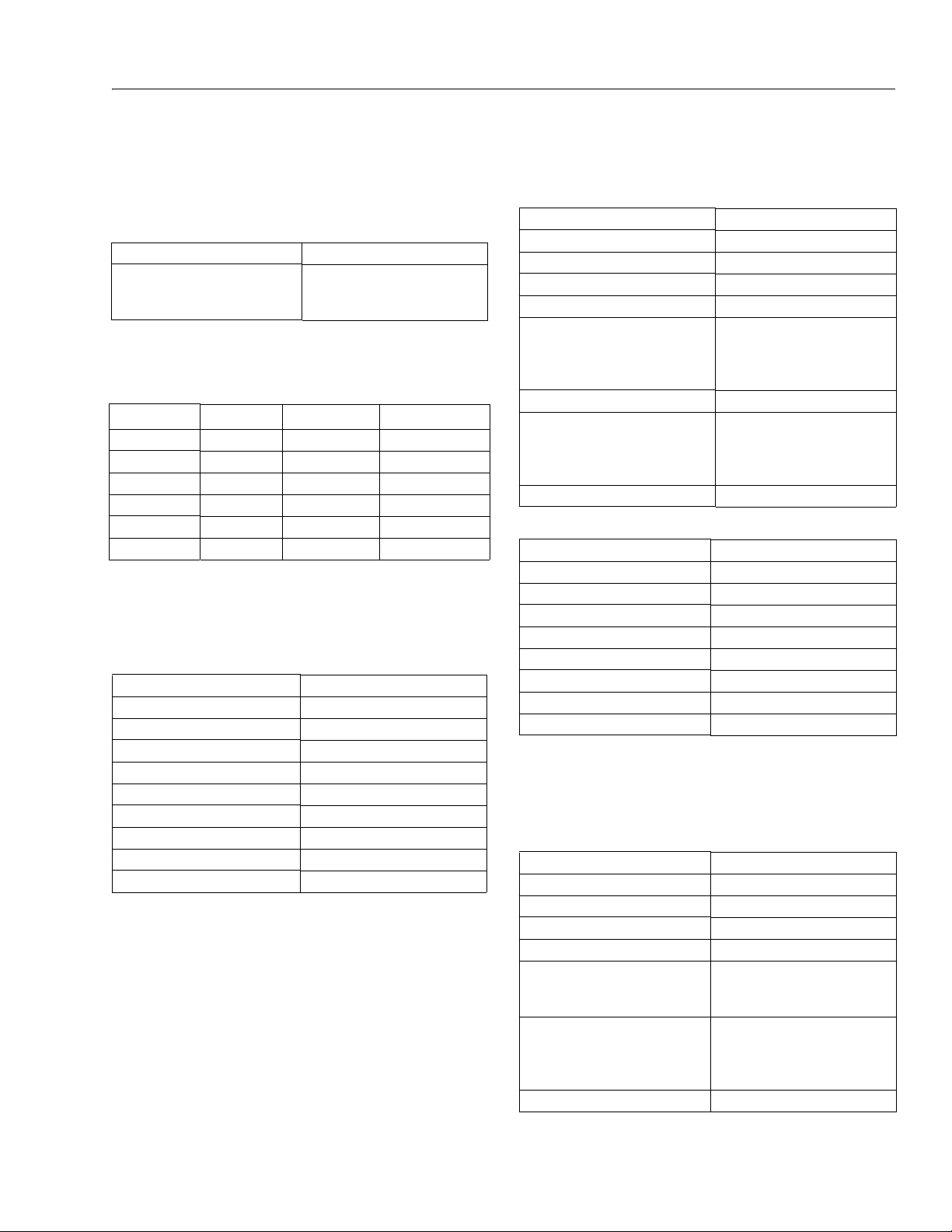
SECTION 1. SPECIFICATIONS
SECTION 1 - SPECIFICATIONS
1.1 CAPACITIES
Table 1-1. Capacities
Fuel Tank 17 gallons (64.3 liters)
Hydraulic Tank 27 gallons (102 liters)
23.6 gal. (89 liters) to the Full line
on the sight gauge
1.2 TIRES
Table 1-2. Tires
Size Type Pressure Weight
12x16.5 Pneumatic 90 psi (6 Bar) 128 lbs. (58 kg)
12x16.5 Foam-Filled N/A 328 lbs. (149 kg)
33/1550x16.5 Pneumatic 90 psi (6 Bar) 135 lbs. (61 kg)
33/1550x16.5 Foam-Filled N/A 395 lbs. (179 kg)
14 x 16.1 Pneumatic 40 lbs. (3 bar) 91.5 lbs. (41.5 kg)
14 x 16.1 Foam-Filled N/A 426 lbs. (193 kg)
1.3 ENGINE
NOTE: RPM Tolerances are ± 100.
Table 1-3. Caterpillar 3024/C2.2
Fuel Diesel
No. of Cylinders 4
BHP 46.5 hp (34 kW)
Bore 3.307 in. (84 mm)
Stroke 3.9370 in. (112 mm)
Displacement 134.3 cu. in. (2.2L)
Oil Capacity 10 qt. (9.4 L)
Compression Ratio 19:1
Firing Order 1-3-4-2
Max. RPM 2800
Fuel Diesel
No. of Cylinders 3
Bore 3.7 in. (94 mm)
Stroke 4.4 in. (112 mm)
Displacement 142 cu. in. (2331 cm³)
Oil Capacity
cr a nk ca s e
co o le r
total capacity
Low RPM 1200
Mid RPM
Tower Lift, Upper Lift, Tele
Sw i ng , B a sk et L ev el , Ba sk e t
Rotate, Jib Lift
High RPM 2800
Fuel Diesel
No. of Cylinders 4
BHP 50 HP (37.3 kW )
Bore 3.3 in. (84 mm)
Stroke 3.9 in. (100 mm)
Firin g Orde r 1-3-4-2
Displacement 135 cu.in. (2.2 L)
Oil Capacity w/filter 10 qt. (9.4 L)
Compression Ratio 23.3:1
Table 1-4. Deutz F3M2011F/D2011L03
6.3 quarts (6 L)
4.75 quarts (4.5 L)
11 quarts (10.5 L)
1800
1500
Table 1-5. Perkins 404C-22
1.4 SPECIFICATIONS AND PERFORMANCE DATA
Dimensional Data
Table 1-6. Dimensional Data
Overall Width 7.4 ft. (2.26 m)
Tailswing 0
Stowed Height 7.4 ft. (2.26 m)
Stowed Length 25.1 ft. (7.68 m)
Wheel base 7.67 ft. (2.34 m)
Tur nin g Ra diu s
6 .5 f t. ( 2. 0 m)
1 6. 4 ft . (5 . 0 m )
Track Width
(12 x 16.5 tire)
(33/1550 tire)
(14 x 16.1 tire)
Ground Clearance 1.18 ft. (0.36 m)
6 .5 f t. ( 2. 0 m)
1 6. 4 ft . (5 . 0 m )
65.3 in. (1.66 m)
66.3 in. (1.69 m)
66.6 in. (1.69 m)
3121181 – JLG Lift – 1-1
Page 18

SECTION 1 - SPECIFICATIONS
Reach Specifications
Table 1-7. Reach Specifications
Max. Platform Height 51.8 ft. (15.81 m)
Max. Horizontal Reach 31.1 ft. (9.48 m)
Up & Over Height 24.08 ft. (7.34 m)
Jib Length 4.5 ft. (1.37 m)
Jib Angle 135° (+70°, -65°)
Chassis
Table 1-8. Chassis Specifications
Swing 357° non-continuous
Platform Capacity 500 lbs. (230 kg)
Rated Gradeability 40%
Max. Tire Load 7900 lb. (3583 kg)
Max. Ground Bearing Pressure
S td . T i re
Fl o ta t io n Ti r e
Axle Oscillation 8 in. (0.2 m)
Drive Speed 4.5 mph (7.2 kph)
System Voltage 12 Volts
Max. Hydraulic System Operating
Pressure
Gross Machine Weight 16,104 lbs. (7305 kg)
48 psi (3.37 kg/cm
36 psi (2.53 kg/cm
4500 psi
(310 bar)
1.5 FUNCTION SPEEDS
Table 1-9. Function Speeds (In Seconds)
Machine Orientation When Doing Speed Tests
Lift: Boom Retracted. Telescope Retracted. Lift Up, Record
Time, Lift Down, Record Time.
Swing: Boom at Full Elevation. Telescope Retracted. Swing the
Turntable to the end stop. Swing the Opposite Direction,
Record Time.
Te le sc o pe : Boom at Full Elevation; Telescope Retracted; Telescope Out, Record Time. Telescope In, Record Time.
Drive: Test to be done on a smooth level surface. Drive Select
Switch should be set at 2WD High Engine. Start approximately
25 ft. (7.62 m) from starting point so that the unit is at maximum speed when starting the test. Results should be recorded
for a 200 ft. (60.96 m) course. Drive Forward, record time. Drive
Reverse, Record Time.
Drive (Above Horizontal): Test should be done on a smooth
level surface. Set Drive Select Switch to High Engine, High
Drive. The Platform Speed Knob should be selected out of the
2)
2)
creep speed. This verifies switches are working when boom is
above horizontal. Results should be recorded for a 50 ft.
course. Drive Forward, Record Time. Drive Reverse, Record
Time.
Platform Rotate: Platform level and completely rotated one
direction. Rotate the opposite direction, Record Time. Rotate
the other direction, Record Time.
Articulating Jib: Platform level and centered with the boom.
Start with the Jib down. Jib Up, Record Time. Jib Down, Record
Time.
Lower Lift: Upper Boom horizontal. Telescoped In. Lower Lift
Up, Record Time. Lower Lift Down, Record Time.
Function Speed
Main Lift Up 24-28
Main Lift Down 20-24
Swing Right & Left* 85-95
Telescope Out 18-22
Telescope In 12-16
Platform R otate Right & Left** 25-32
Jib Up 21-31
Jib Down 19-25
Lower Lift Up 30-38
Lower Lif t Down 22-28
Drive (4WD High Engine) 29-31
(4.5 MPH)
Drive above Horizontal
(50 ft.)
*Max 10% Difference Between Left & Right
**Max 15% Difference Between Left & Right
46-68
(0.75 - 0.50
MPH)
Test Notes
1. Start Stop watch with function, not controller or switch.
2. Drive test results reflect 12x16.5 tires.
3. All speed tests are run from the platform. Speeds do not
reflect ground control operation.
4. Platform speed knob control must be at full speed
(turned clockwise completely).
5. Function speeds may vary due to cold, thick hydraulic
oil. Test should be run with oil temperature above 100° F
(38° C).
6. Some flow control functions may not work with the
speed knob clicked into creep position.
1-2 – JLG Lift – 3121181
Page 19
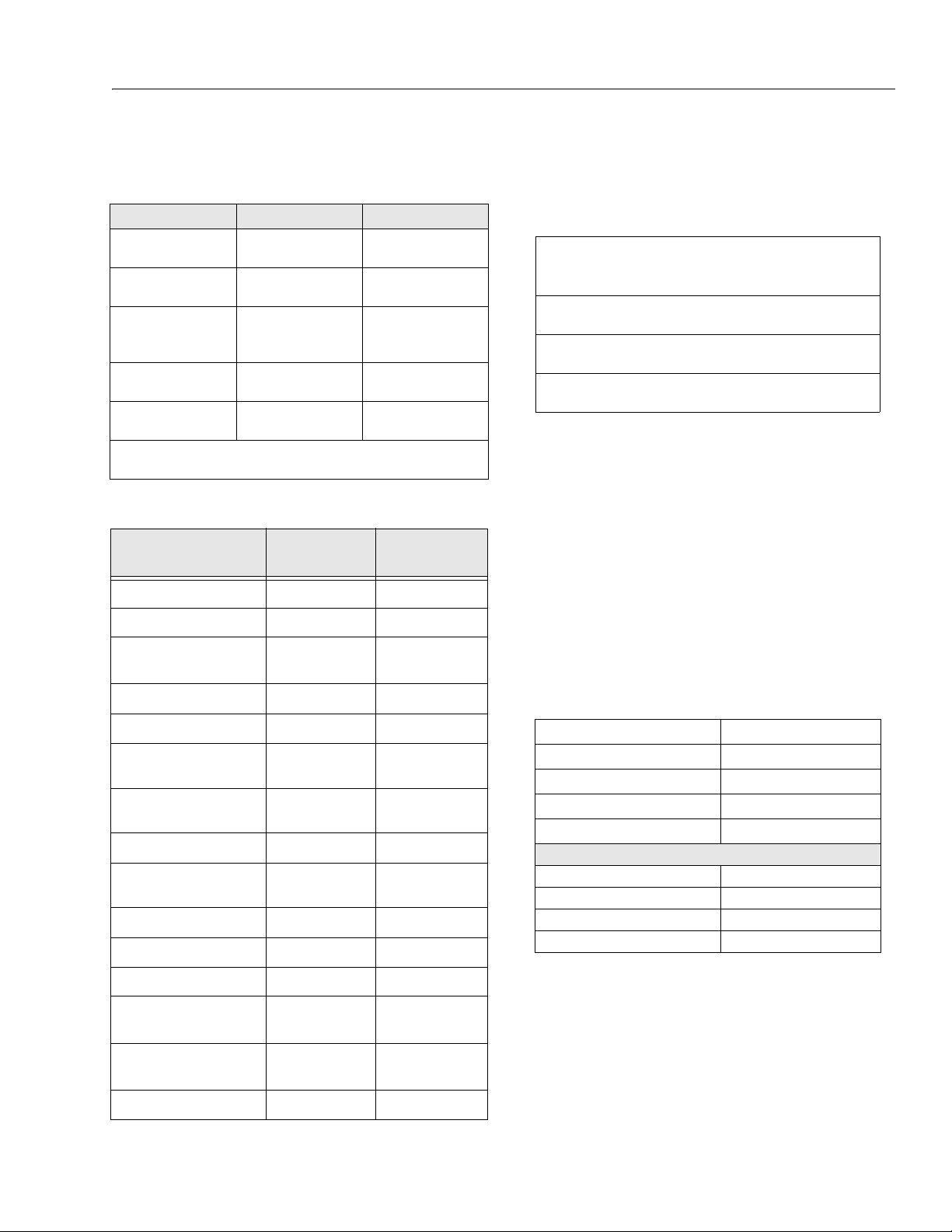
1.6 TORQUE REQUIREMENTS 1.7 LUBRICATION
Table 1-13. Mobilfluid 424 Specs
SAE Grade 10W30
Gravity, API 29.0
Density, Lb/Gal. 60°F 7.35
Pour Point, Max -46°F (-43°C)
Flash Point, Min. 442°F (228°C)
Viscosity
Brookfield, cP at -18°C 2700
at 40° C 55 cSt
at 100° C 9.3 cSt
Viscos ity Ind ex 152
SECTION 1 - SPECIFICATIONS
Table 1-10. Torque Specification
Description Torque Va l ue Interval Hours
Wheel Lugs 170 ft. lbs.
(230 Nm)
Swing Bearing
(Loctite)
Starter Solenoid
Co n ta c t s
Co i l
Drive Hub to Axle 240 ft. lbs.
Drive Motor to Axle 120 ft. lbs.
*Check swing bearing bolts for security after first 50 hours of operation and every 600 hours thereafter.
Table 1-11. Engine Torque Requirements
Description
Cylin der Head Cover 6 8.5
Cyind er Head C over 6 8.5
Rocker Arm Adjust ment
Screw
Intake Manifold 6 8.5
240 ft. lbs.
(325 Nm)
95 in. lbs. (9.5 Nm)
40 in. lbs. (4 Nm)
(325 Nm)
(163 Nm)
Torque Va l u e
Ft. Lb.s
15 21
150
50/600*
As required
As required
As required
Torque Va l ue
Nm
Hydraulic Oil
Table 1-12. Hydraulic Oil
Hydraulic System
Operating
Temperature Range
+0° to + 180° F
(-18° to +83° C)
+0° to + 210° F
(-18° to +99° C)
+50° to + 210° F
(+10° to +99° C
NOTE: Hydraulic oils must have anti-wear qualities at least to API
Service Classification GL-3, and sufficient chemical stability for mobile hydraulic system service. JLG Industries recommends Mobilfluid 424 hydraulic oil, with an SAE
viscosity index of 152.
NOTE: When temperatures remain consistently below 20 degrees
F. (-7 degrees C.), JLG Industries recommends the use of
Mobil DTE13.
Aside from JLG recommendations, it is not advisable to mix oils of
different brands or types, as they may not contain the same
required additives or be of comparable viscosities. If use of
hydraulic oil other than Mobilfluid 424 is desired, contact JLG
Industries for proper recommendations.
S.A.E. Viscosity
Grade
10W
10W-20, 10W30
20W-20
Air Intake Pipe 15 21
Exhaust Manifold
(F3M1011)
Exhaust Manifold
(F3M2011)
Pump Co upling (dry) 26.5 37
Pump Co upling
#242)
Oil Drain Plug 39 55
Oil Pan (sheet metal) 15 21
Oil Pan (cast) 22 31
Injection Line Attachment
Injection Valve Attachment
Lube Oil Fil ter Cartrid ge 19 27
3121181 – JLG Lift – 1-3
(Loctite
28.5 40
16 22
28.5 40
21 30
15 21
Page 20
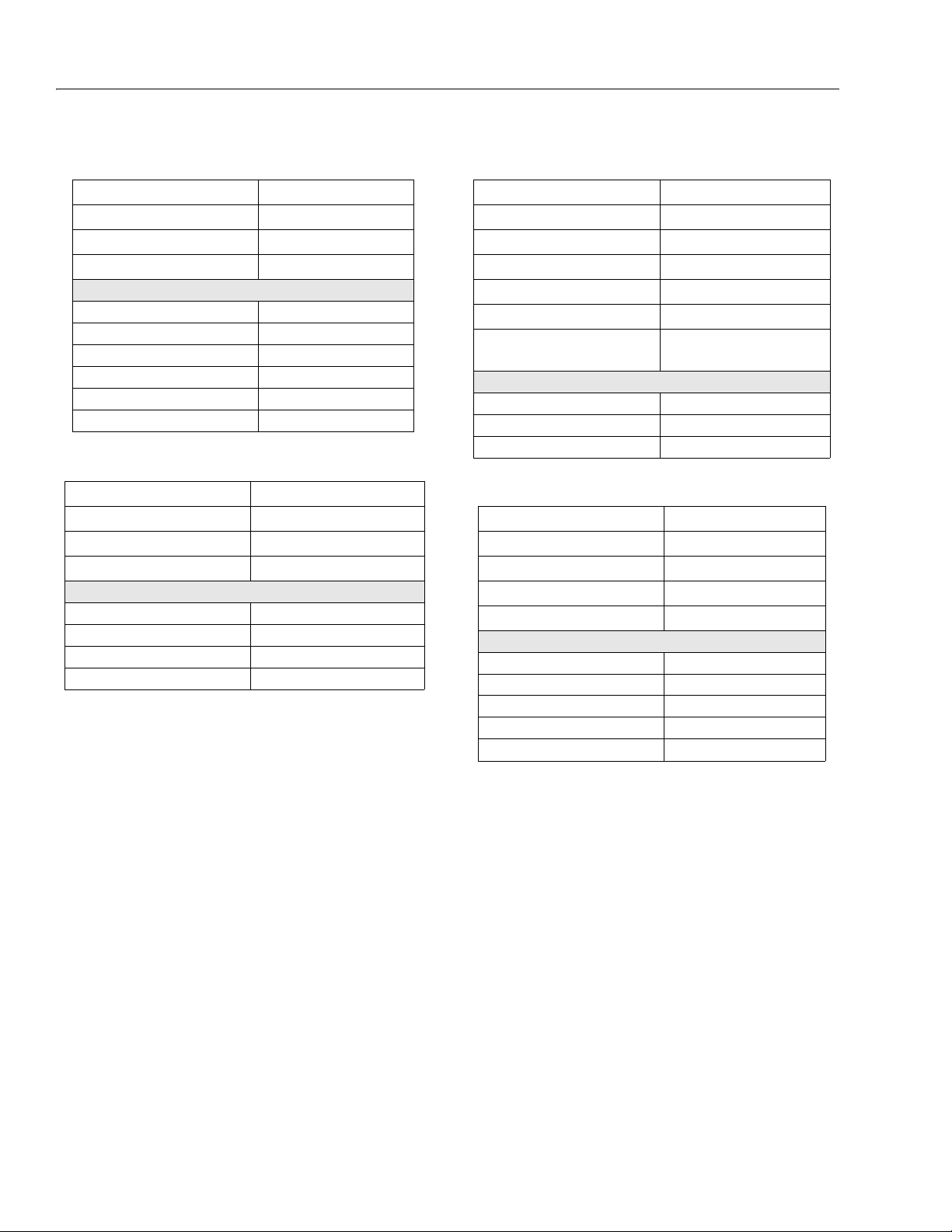
SECTION 1 - SPECIFICATIONS
Table 1-14. Mobil DTE 13M Specs
ISO Viscosity Grade #32
Specific Gravity 0.877
Pour Point, Max -40°F (-40°C)
Flash Point, Min. 330°F (166°C)
Viscosity
at 40° C 33cSt
at 100° C 6.6 cSt
at 100° F 169 SUS
at 210° F 48 SUS
cp at -20° F 6,200
Viscos ity Ind ex 140
Table 1-15. UCon Hydrolube HP-5046
Type Synthetic Biodegradable
Specific Gravity 1.082
Pour Point, Max -58°F (-50°C)
pH 9.1
Viscosity
at 0° C (32° F) 340 cSt (1600SUS)
at 40° C (104° F) 46 cSt (215SUS)
at 65° C (150° F) 22 cSt (106SUS)
Viscosity Index 170
Table 1-16. Mobil EAL H 46 Specs
Type Synthetic Biodegradable
ISO Viscosity Grade 46
Specific Gravity .910
Pour Point -44°F (-42°C)
Flash Point 500°F (260°C)
Operating Temp. 0 to 180°F (-17 to 162°C)
Weight
7.64 lb. per gal.
(0.9 kg per liter)
Viscosity
at 40° C 45 cSt
at 100° C 8.0 cSt
Viscos ity Ind ex 153
Table 1-17. Quintolubric 888-46
Density
0.91 @ 15°C (59°F)
Pour Point
<-20°C (<-4°F)
Flash Point
275°C (527°F)
Fire Point
325°C (617°F)
Autoignition Temperature
450°C (842°F)
Viscosity
at 0° C (32°F) 360 cSt
at 20° C (68°F) 102 cSt
at 40° C (104°F) 46 cSt
at 100° C (212°F) 10 cSt
Viscosity Index 220
1-4 – JLG Lift – 3121181
Page 21
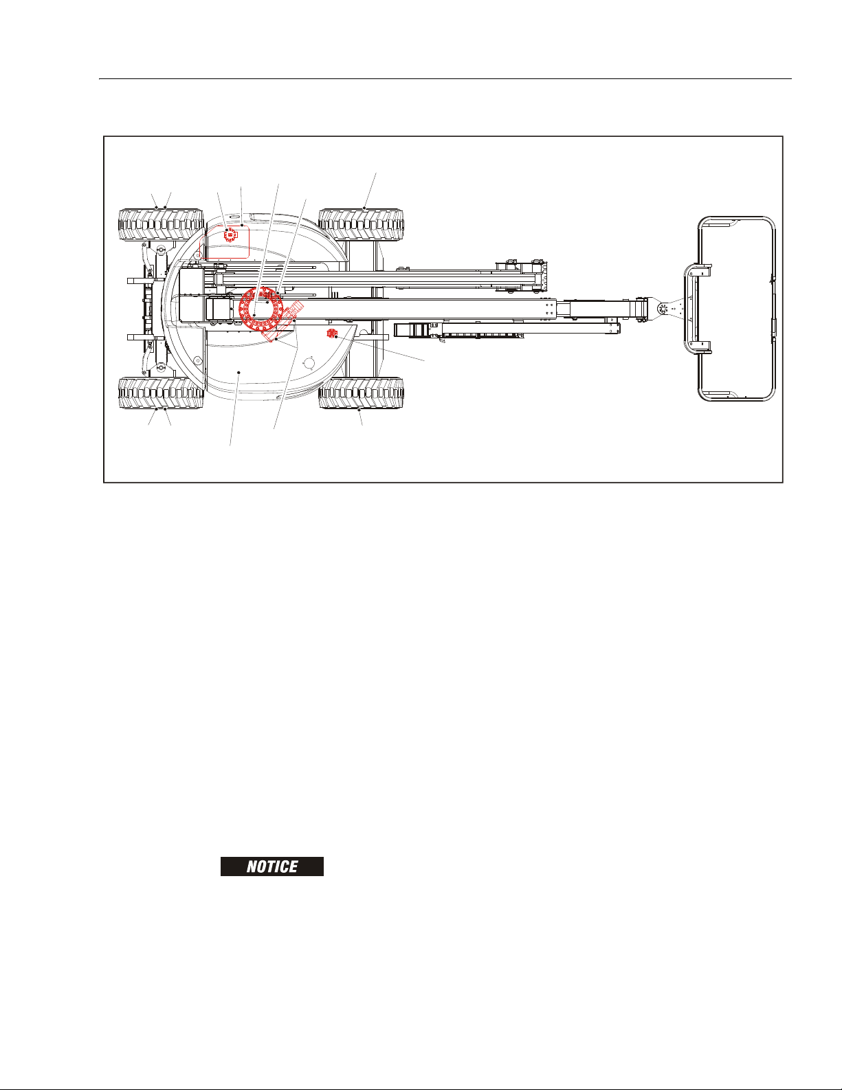
SECTION 1 - SPECIFICATIONS
Figure 1-1. Operator Maintenance and Lubrication Diagram
2B
3
4
3
4
5
7,8
1
4
2A
6
4
9,10,11,12,13
1.8 OPERATOR MAINTENANCE
NOTE: The following numbers correspond to those in Figure 1-1.,
Operator Maintenance and Lubrication Diagram.
1. Swing Bearing - Internal Ball Bearing
Lube Point(s) - 2 Grease Fittings
Capacity - A/R
Lube - MPG
Interval - Every 3 months or 150 hrs of operation
Table 1-18. Lubrication Specifications
KEY SPECIFICATIONS
MPG Multipurpose Grease having a minimum dripping point of
350° F (177° C). Excellent water resistance and adhesive qualities, and being of extreme pressure type.
(Timken OK 40 pounds minimum. )
EPGL Extreme Pressure Gear Lube (oil) meeting API service classifi-
2. A. Swing Bearing - Teeth
Lube Point(s) - Spray On
Capacity - A/R
Lube - OGL
Interval - Every 3 months or 150 hrs of operation
Comments - More frequent lubrication intervals may
be required
cation GL-5 or MIL-Spec MIL-L-2105
HO Hydraulic Oil. API service classification GL-3, e.g. Mobilfluid
424.
EO Engine (crankcase) Oil. Gas - API SF, SH, SG class, MIL-L-2104.
Diesel - API CC/CD class, MIL-L-2104B/MIL-L-2104C.
OGL Open Gear Lubricant - Mobiltac 375 or equivalent.
B. End Bearings - Worm Gear*
Lube Point(s) - 2 Grease Fittings
Capacity - A/R
Lube - MPG
Interval - Every 2 years or 1200 hrs of operation
Comments - Remove grease fittings and install
plugs after greasing
LUBRICATION INTERVALS ARE BASED ON MACHINE OPERATION UNDER NORMAL CONDITIONS. FOR MACHINES
USED IN MULTI-SHIFT OPERATIONS AND/OR EXPOSED TO
HOSTILE ENVIRONMENTS OR CONDITIONS, LUBRICATION
FREQUENCIES MUST BE INCREASED ACCORDINGLY.
NOTE: It is recommended as a good practice to replace all filters
at the same time.
3121181 – JLG Lift – 1-5
Page 22
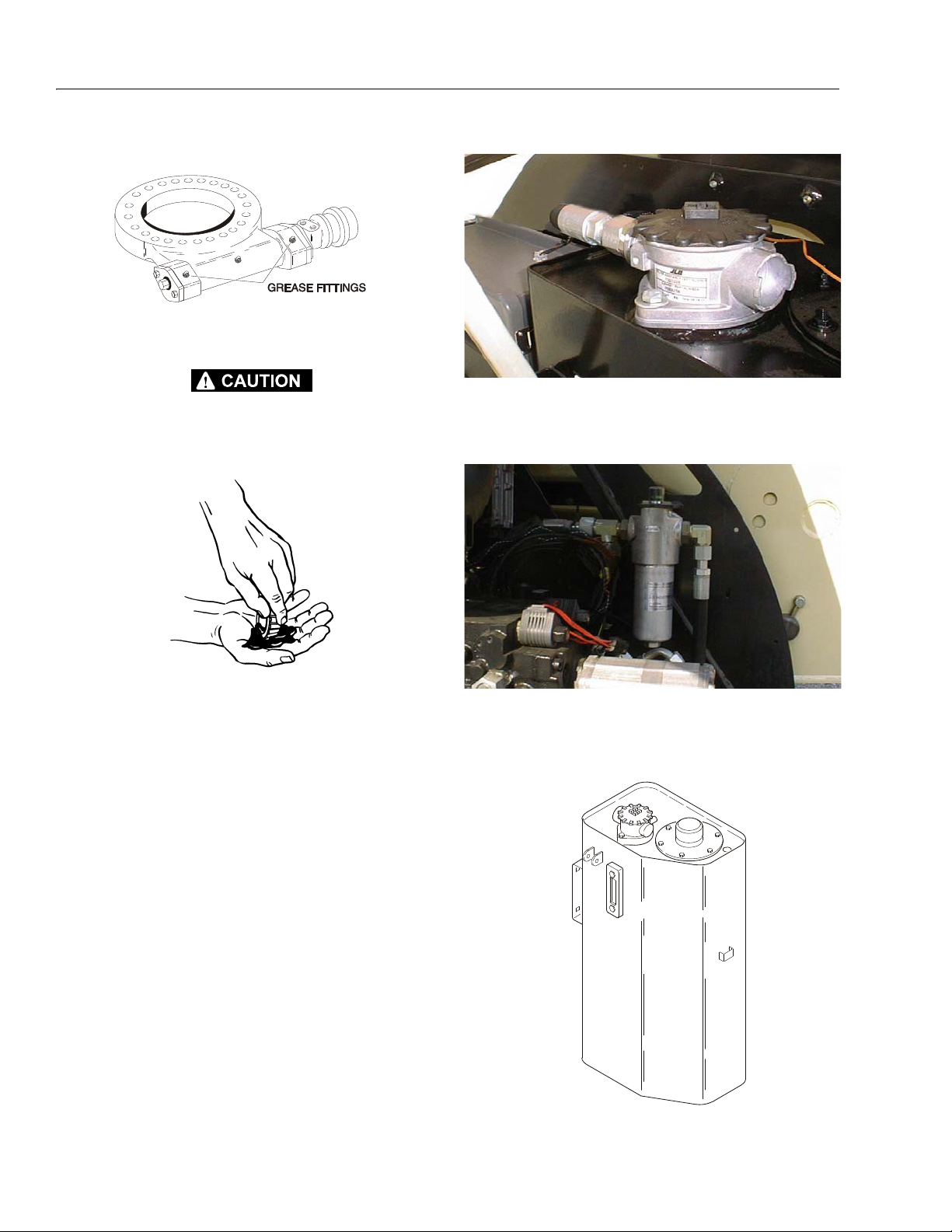
SECTION 1 - SPECIFICATIONS
*If necessary install grease fittings into worm gear
housing and grease bearings.
5. Hydraulic Return Filter
DO NOT OVER-GREASE END BEARINGS. OVER-GREASING
BEARINGS WILL BLOW OUTER SEAL IN HOUSING.
3. Wheel Bearings (2WD Only)
Lube Point(s) - Repack
Capacity - A/R
Lube - MPG
Interval - Every 2 years or 1200 hours of operation
4. Wheel Drive Hub
Lube Point(s) - Level/Fill Plug
Capacity - 17 oz. (0.5 L) - 1/2 Full
Lube - EPGL
Interval - Check level every 3 months or 150 hrs of
operation; change every 2 years or 1200 hours of
operation.
Interval - Change after first 50 hrs. and every 6
months or 300 hrs. thereafter or as indicated by
Condition Indicator.
6. Hydraulic Charge Filter
Interval - Change after first 50 hrs. and every 6
months or 300 hrs. thereafter or as indicated by
Condition Indicator.
7. Hydraulic Tank
1-6 – JLG Lift – 3121181
Page 23
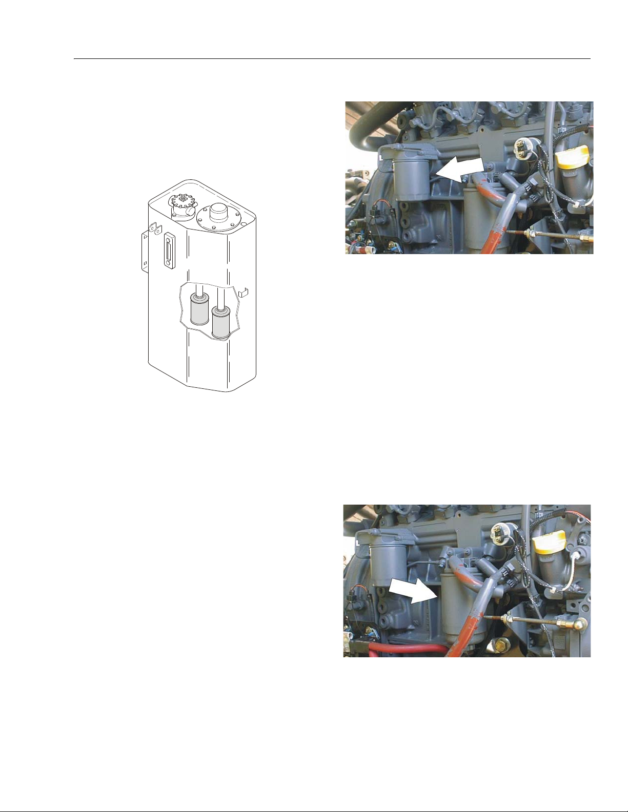
SECTION 1 - SPECIFICATIONS
Lube Point(s) - Fill Cap
Capacity - 27 gallons (102 liters); 23.6 gal. (89 liters)
to the Full line on the sight gauge
Lube - HO
Interval - Check Level daily; Change every 2 years or
1200 hours of operation.
8. Suction Strainers
Lube Point(s) - 2
Interval - Every 2 years or 1200 hours of operation,
remove and clean at time of hydraulic oil
change.
9. Oil Change w/Filter - Caterpillar
Lube Point(s) - Fill Cap/Spin-on Element
Capacity - 10 Quarts (9.4 L)
Lube - EO
Interval - Every Year or 600 hours of operation.
Comments - Check level daily/Change in accordance with engine manual.
10. Oil Change w/Filter - Deutz
Lube Point(s) - Fill Cap/Spin-on Element
Capacity - 11 Quarts(10.5 L) Crankcase; 5 Quarts
(4.7 L) Cooler
Lube - EO
Interval - Every Year or 1200 hours of operation
Comments - Check level daily/Change in
accordance with engine manual.
11. Oil Change w/Filter - Perkins
Lube Point(s) - Fill Cap/Spin-on Element (JLG P/N
7026855)
Capacity - 10 Quarts (9.4 L)
Lube - EO
Interval - Every Year or 600 hours of operation
Comments - Check level daily/Change in accordance
with engine manual.
12. Fuel Filter - Caterpillar
Lube Point(s) - Replaceable Element
Interval - Every Year or 600 hours of operation.
13. Fuel Filter - Deutz
Lube Point(s) - Replaceable Element
Interval - Every Year or 600 hours of operation
14. Fuel Filter - Perkins
Lube Point(s) - Replaceable Element
Interval - Every Year or 600 hours of operation
3121181 – JLG Lift – 1-7
Page 24
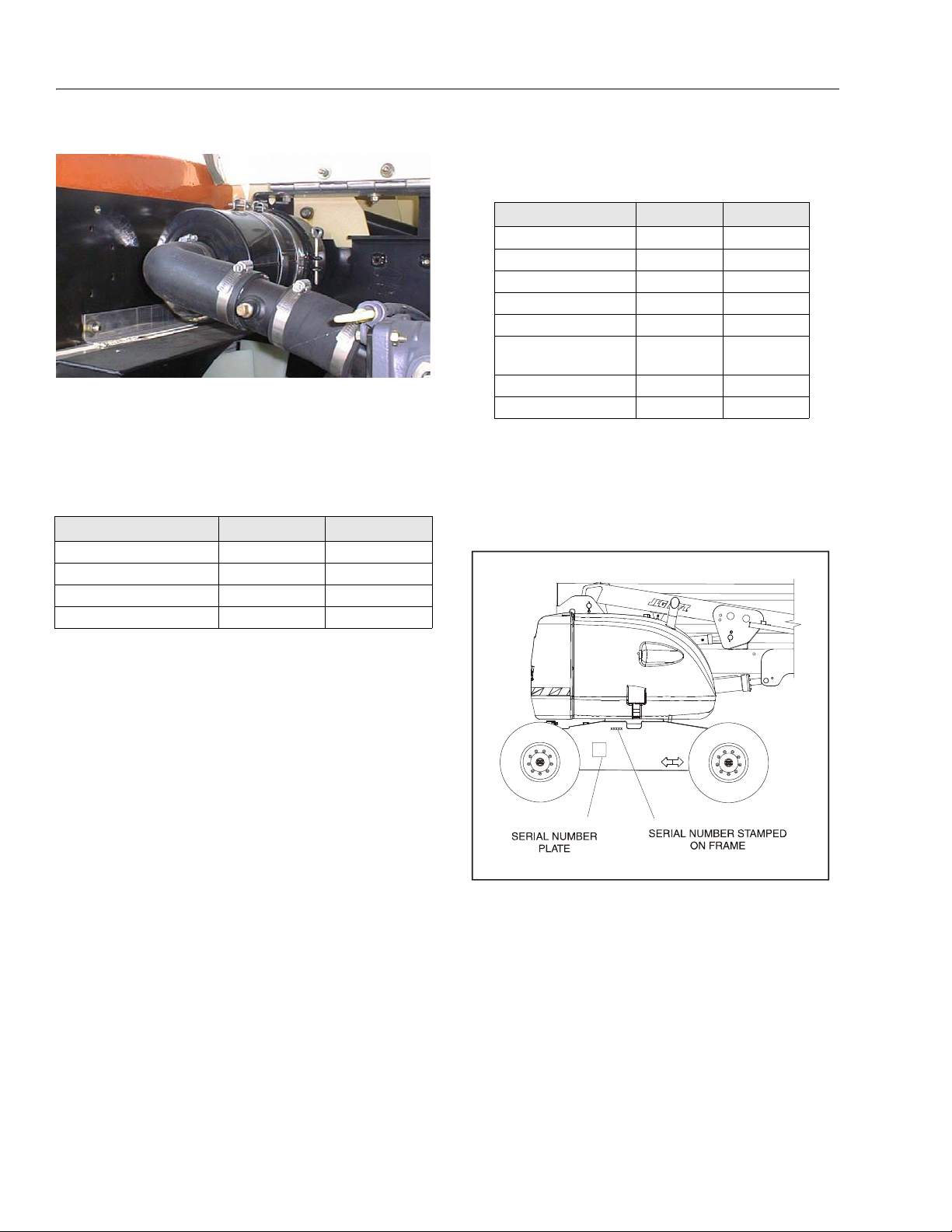
SECTION 1 - SPECIFICATIONS
Figure 1-2. Serial Number Locations
15. Air Filter
Lube Point(s) - Replaceable Element
Interval - Every 6 months or 300 hours of operation or as
indicated by the condition indicator
1.9 MAJOR COMPONENT WEIGHTS
Table 1-19. Component Weights
Component Pounds Kilograms
Engine Only 440 200
Upper Boom 1257 570
Frame (Bare) 2105 955
Turntable (Bare) 1533 695.5
1.10 PRESSURE SETTINGS
Table 1-20. Pressure Settings
SETTING PSI BAR
Bang-Bang Main Relief 3300 227.5
Steer 2500 172
Platform Level Up 2800 193
Platform Level Down 1800 124
Articulating Jib 1500 103
Proportional Main
Relief
Lift Down 1200 83
Swing 1700 117
3200 220
1.11 SERIAL NUMBER LOCATION
A serial number plate is affixed to the left rear side of the
frame. If the serial number plate is damaged or missing, the
machine serial number is stamped on the left side of the
frame.
1-8 – JLG Lift – 3121181
Page 25
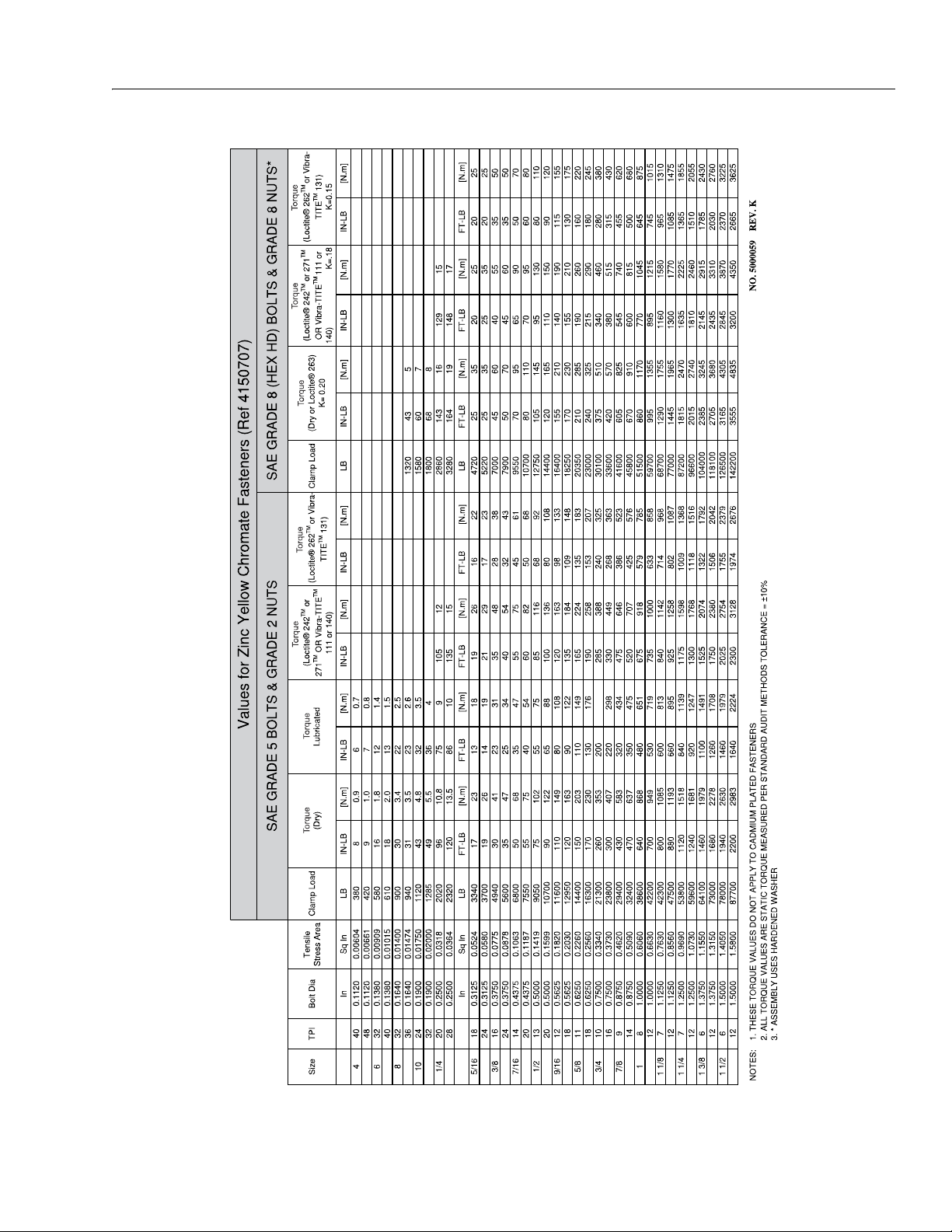
SECTION 1 - SPECIFICATIONS
Figure 1-3. Torque Chart - Sheet 1 of 5 - (SAE Fasteners)
3121181 – JLG Lift – 1-9
Page 26
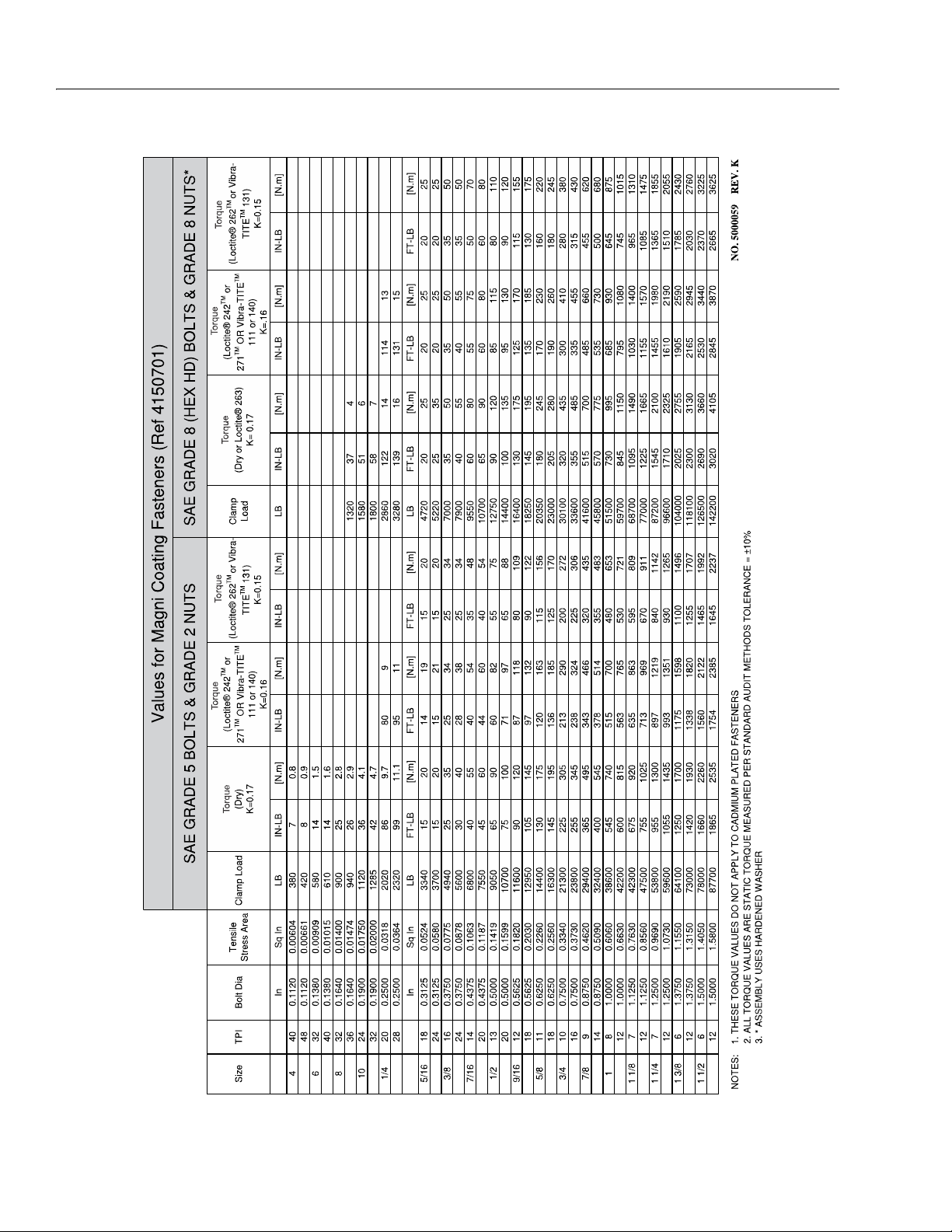
SECTION 1 - SPECIFICATIONS
Figure 1-4. Torque Chart - Sheet 2 of 5 - (SAE Fasteners)
1-10 – JLG Lift – 3121181
Page 27
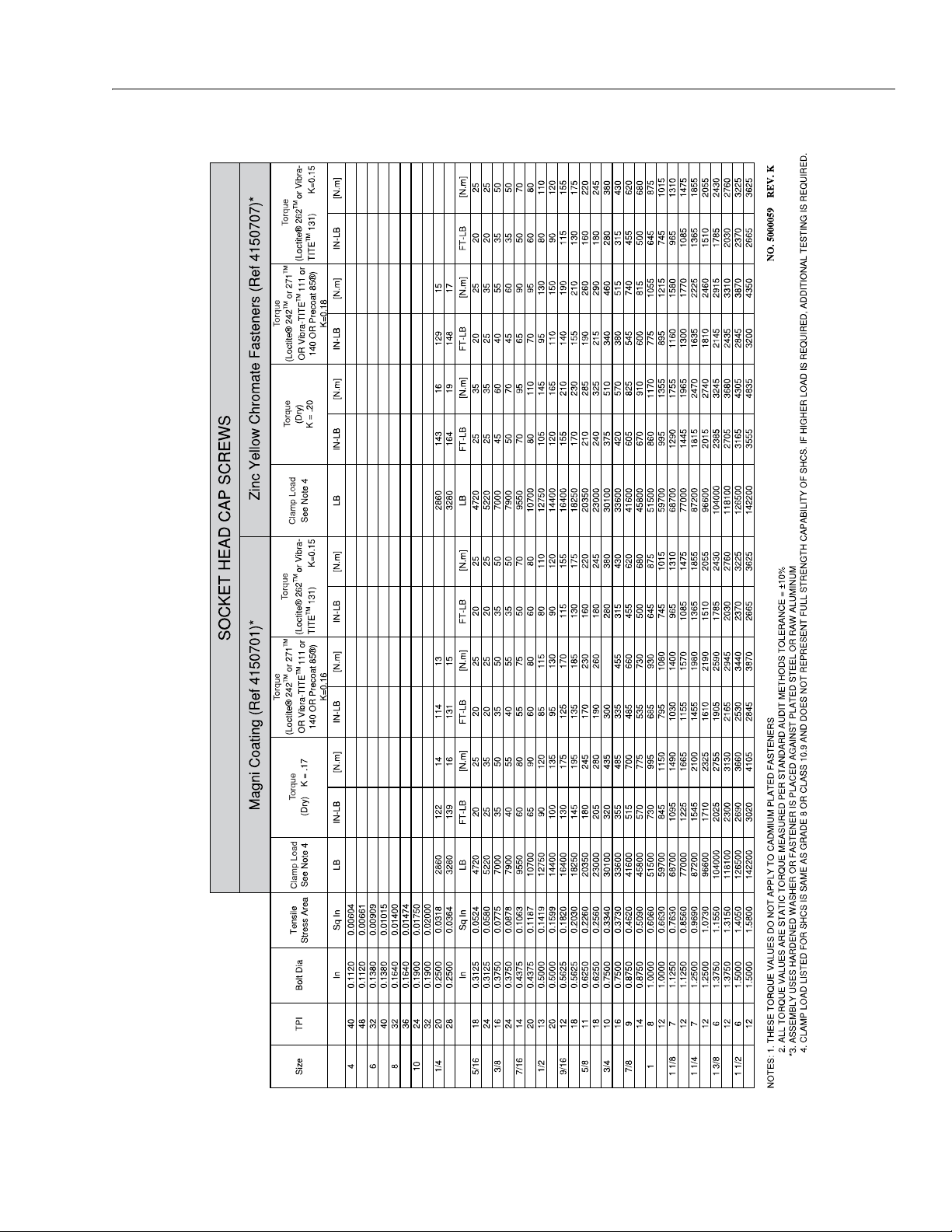
SECTION 1 - SPECIFICATIONS
Figure 1-5. Torque Chart - Sheet 3 of 5 - (SAE Fasteners)
3121181 – JLG Lift – 1-11
Page 28
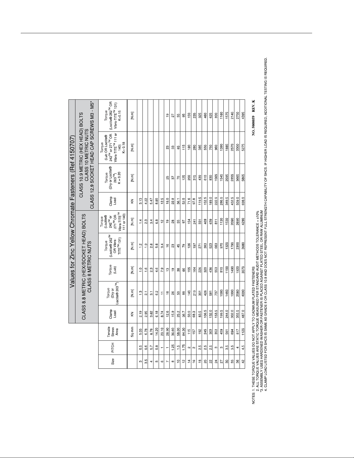
SECTION 1 - SPECIFICATIONS
Figure 1-6. Torque Chart - Sheet 4 of 5 - (METRIC Fasteners)
1-12 – JLG Lift – 3121181
Page 29
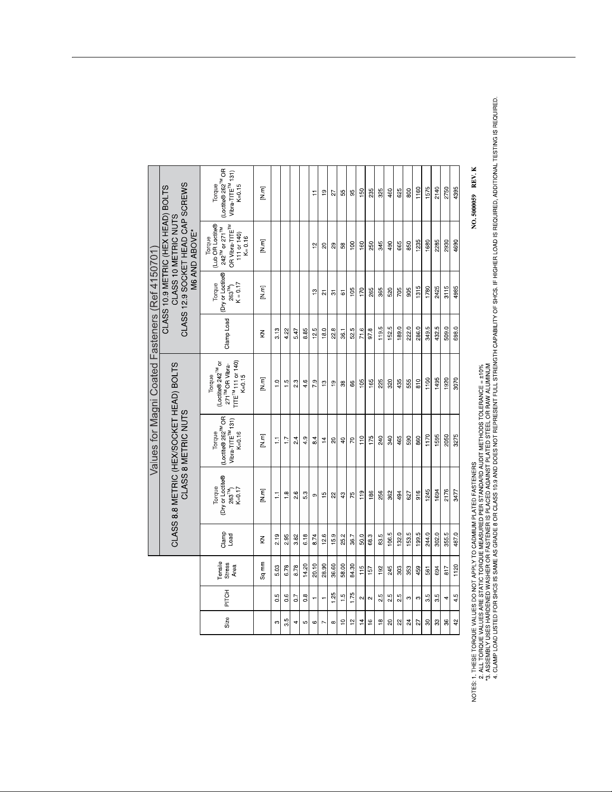
SECTION 1 - SPECIFICATIONS
Figure 1-7. Torque Chart - Sheet 5 of 5 - (METRIC Fasteners)
3121181 – JLG Lift – 1-13
Page 30

SECTION 1 - SPECIFICATIONS
NOTES:
1-14 – JLG Lift – 3121181
Page 31

SECTION 2. GENERAL
SECTION 2 - GENERAL
2.1 MACHINE PREPARATION, INSPECTION, AND MAINTENANCE
General
This section provides the necessary information needed by
those personnel that are responsible to place the machine in
operation readiness and maintain its safe operating condition.
For maximum service life and safe operation, ensure that all
the necessary inspections and maintenance have been completed before placing the machine into service.
Preparation, Inspection, and Maintenance
It is important to establish and conform to a comprehensive
inspection and preventive maintenance program. The following table outlines the periodic machine inspections and maintenance recommended by JLG Industries, Inc. Consult your
national, regional, or local regulations for further requirements
for aerial work platforms. The frequency of inspections and
maintenance must be increased as environment, severity and
frequency of usage requires.
Pre-Start Inspection
It is the User’s or Operator’s primary responsibility to perform a
Pre-Start Inspection of the machine prior to use daily or at
each change of operator. Reference the Operator’s and Safety
Manual for completion procedures for the Pre-Start Inspection. The Operator and Safety Manual must be read in its
entirety and understood prior to performing the Pre-Start
Inspection.
Pre-Delivery Inspection and Frequent Inspection
The Pre-Delivery Inspection and Frequent Inspection shall be
performed by a qualified JLG equipment mechanic. JLG Industries, Inc. recognizes a qualified JLG equipment mechanic as a
person who, by possession of a recognized degree, certificate,
extensive knowledge, training, or experience, has successfully
demonstrated the ability and proficiency to service, repair, and
maintain the subject JLG product model.
Pre-Delivery Inspection and Frequent Inspection procedures
are performed in the same manner, but at different times. The
Pre-Delivery Inspection shall be performed prior to each sale,
lease, or rental delivery. The Frequent Inspection shall be
accomplished for each machine in service for 3 months or 150
hours (whichever comes first); out of service for a period of
more than 3 months; or when purchased used. The frequency
Table 2-1. Inspection and Maintenance
of this inspection must be increased as environment, severity
and frequency of usage requires.
Reference the JLG Pre-Delivery and Frequent Inspection Form
and the Inspection and Preventative Maintenance Schedule
for items requiring inspection during the performance of
these inspections. Reference the appropriate areas of this
manual for servicing and maintenance procedures.
Annual Machine Inspection
The Annual Machine Inspection must be performed by a Factory-Certified Service Technician on an annual basis, no later
than thirteen (13) months from the date of the prior Annual
Machine Inspection. JLG Industries, Inc. recognizes a FactoryCertified Service Technician as a person who has successfully
completed the JLG Service Training School for the subject JLG
product model. Reference the machine Service and Maintenance Manual and appropriate JLG inspection form for performance of this inspection.
Reference the JLG Annual Machine Inspection Form and
Inspection and Preventative Maintenance Schedule for items
requiring inspection during performance of this inspection.
Reference appropriate areas of this manual for servicing and
maintenance procedures.
For the purpose of receiving safety-related bulletins, it is
important that JLG Industries, Inc. has updated ownership
information for each machine. When performing each Annual
Machine Inspection, notify JLG Industries, Inc. of the current
machine ownership.
Preventative Maintenance
In conjunction with the specified inspections, maintenance
shall be performed by a qualified JLG equipment mechanic.
JLG Industries, Inc. recognizes a qualified JLG equipment
mechanic as a person who, by possession of a recognized
degree, certificate, extensive knowledge, training, or experience, has successfully demonstrated the ability and proficiency to service, repair, and maintain the subject JLG product
model.
Reference the Preventative Maintenance Schedule and the
appropriate areas of this manual for servicing and maintenance procedures. The frequency of service and maintenance
must be increased as environment, severity and frequency of
usage requires.
Typ e F req uen cy
Primary
Responsibility
Service
Qualification
Reference
3121181 – JLG Lift – 2-1
Page 32

SECTION 2 - GENERAL
Table 2-1. Inspection and Maintenance
Pre- Start I nspection
Pre-Delivery
Inspection
Frequent Inspec-
tion
Annual Machine
Inspection
Preventative
Maintenance
Prior to use each day; or
At each Operator change.
Prior to each sale, lease, or
rental delivery.
In service for 3 months or 150 hours,
whichever comes first; or
Out of service for a period of more than
3 months; or
Purchas ed used.
Annually, no later than 13 months
from the date of the prior inspection.
At intervals as specified in the Service
and Maintenance Manual.
2.2 SERVICE AND GUIDELINES
General
The following information is provided to assist you in the use
and application of servicing and maintenance procedures
contained in this book.
Safety and Workmanship
Your safety, and that of others, is the first consideration when
engaging in the maintenance of equipment. Always be conscious of weight. Never attempt to move heavy parts without
the aid of a mechanical device. Do not allow heavy objects to
rest in an unstable position. When raising a portion of the
equipment, ensure that adequate support is provided.
Cleanliness
User or Operator User or Operator Operator and Safety Man-
ual
Owner, Dealer, or
User
Owner, Dealer, or
User
Owner, Dealer, or
User
Owner, Dealer, or
User
3. Clean and inspect all parts during servicing or maintenance, and assure that all passages and openings are
unobstructed. Cover all parts to keep them clean. Be
sure all parts are clean before they are installed. New
parts should remain in their containers until they are
ready to be used.
Qualified JLG
Mechanic
Qualified JLG
Mechanic
Factory-Certified
Service Techni-
cian
Qualified JLG
Mechanic
Service and Maintenance
Manual and applicable JLG
inspection form.
Service and Maintenance
Manual and applicable JLG
inspection form.
Service and Maintenance
Manual and applicable JLG
inspection form.
Service and Maintenance
Manual
Components Removal and Installation
1. Use adjustable lifting devices, whenever possible, if
mechanical assistance is required. All slings (chains,
cables, etc.) should be parallel to each other and as near
perpendicular as possible to top of part being lifted.
2. Should it be necessary to remove a component on an
angle, keep in mind that the capacity of an eyebolt or
similar bracket lessens, as the angle between the supporting structure and the component becomes less
than 90 degrees.
1. The most important single item in preserving the long
service life of a machine is to keep dirt and foreign materials out of the vital components. Precautions have been
taken to safeguard against this. Shields, covers, seals,
and filters are provided to keep air, fuel, and oil supplies
clean; however, these items must be maintained on a
scheduled basis in order to function properly.
3. If a part resists removal, check to see whether all nuts,
bolts, cables, brackets, wiring, etc., have been removed
and that no adjacent parts are interfering.
Component Disassembly and Reassembly
When disassembling or reassembling a component, complete
2. At any time when air, fuel, or oil lines are disconnected,
clear adjacent areas as well as the openings and fittings
themselves. As soon as a line or component is disconnected, cap or cover all openings to prevent entry of foreign matter.
2-2 – JLG Lift – 3121181
the procedural steps in sequence. Do not partially disassemble
or assemble one part, then start on another. Always recheck
your work to assure that nothing has been overlooked. Do not
make any adjustments, other than those recommended, without obtaining proper approval.
Page 33

SECTION 2 - GENERAL
Pressure-Fit Parts
When assembling pressure-fit parts, use an anti-seize or
molybdenum disulfide base compound to lubricate the mating surface.
Bearings
1. When a bearing is removed, cover it to keep out dirt and
abrasives. Clean bearings in nonflammable cleaning solvent and allow to drip dry. Compressed air can be used
but do not spin the bearing.
2. Discard bearings if races and balls (or rollers) are pitted,
scored, or burned.
3. If bearing is found to be serviceable, apply a light coat of
oil and wrap it in clean (waxed) paper. Do not unwrap
reusable or new bearings until they are ready to install.
4. Lubricate new or used serviceable bearings before
installation. When pressing a bearing into a retainer or
bore, apply pressure to the outer race. If the bearing is to
be installed on a shaft, apply pressure to the inner race.
Gaskets
Check holes in gaskets align with openings in mating parts. If
it becomes necessary to hand-fabricate a gasket, use gasket
material or stock of equivalent material and thickness. Be sure
to cut holes in the right location, as blank gaskets can cause
serious system damage.
Bolt Usage and Torque Application
1. Use bolts of proper length. A bolt which is too long will
bottom before the head is tight against its related part. If
a bolt is too short, there will not be enough thread area
to engage and hold the part properly. When replacing
bolts, use only those having the same specifications of
the original, or one which is equivalent.
2. Unless specific torque requirements are given within the
text, standard torque values should be used on heattreated bolts, studs, and steel nuts, in accordance with
recommended shop practices. (See Torque Chart Section 1.)
Hydraulic Lines and Electrical Wiring
Clearly mark or tag hydraulic lines, electrical wiring, and their
receptacles when disconnecting or removing them from the
unit. This will ensure they are correctly reinstalled.
Hydraulic System
1. Keep the system clean. If evidence of metal or rubber
particles are found in the hydraulic system, drain and
flush the entire system.
2. Disassemble and reassemble parts on clean work surface. Clean all metal parts with non-flammable cleaning
solvent. Lubricate components, as required, to aid
assembly.
Lubrication
Service applicable components with amount, type, and grade
of lubricant recommended in this manual at specified intervals. When recommended lubricants are not available, consult
your local supplier for an equivalent that meets or exceeds the
specifications listed.
Battery
Clean battery, using a non-metallic brush and a solution of
baking soda and water. Rinse with clean water. After cleaning,
thoroughly dry battery and coat terminals with an anti corrosion compound.
Lubrication and Servicing
Components and assemblies requiring lubrication and servicing are shown in the Lubrication Chart in Section 1.
2.3 LUBRICATION AND INFORMATION
Hydraulic System
1. The primary enemy of a hydraulic system is contamination. Contaminants enter the system by various means,
e.g., using inadequate hydraulic oil, allowing moisture,
grease, filings, sealing components, sand, etc., to enter
when performing maintenance, or by permitting pump
to cavitate due to insufficient system warm-up or leaks
in pump supply (suction) lines.
2. Design and manufacturing tolerances of component
working parts are very close, therefore, even the smallest amount of dirt or foreign matter entering a system
can cause wear or damage to components and generally results in faulty operation. Every precaution must be
taken to keep hydraulic oil clean, including reserve oil in
storage. Hydraulic system filters should be checked,
cleaned, and/or replaced as necessary, at the specified
intervals required in the Lubrication Chart in Section 1.
Always examine filters for evidence of metal particles.
3. Cloudy oils indicate a high moisture content which permits organic growth, resulting in oxidation or corrosion.
If this condition occurs, system must be drained,
flushed, and refilled with clean oil.
4. It is not advisable to mix oils of different brands or types,
as they may not contain required additives or be of comparable viscosities. Good grade mineral oils, with viscosities suited to ambient temperatures in which the
machine is operating, are recommended for use.
NOTE: Metal particles may appear in oil or filters of new machines
due to the wear-in of meshing components.
3121181 – JLG Lift – 2-3
Page 34

SECTION 2 - GENERAL
Hydraulic Oil
1. Refer to Section 1 for recommendations for viscosity
ranges.
2. JLG recommends Mobilfluid 424 hydraulic oil, which has
an SAE viscosity of 10W-30 and a viscosity index of 152.
NOTE: Start-up of hydraulic system with oil temperatures below -
15° F (-26° C) is not recommended. If it is necessary to start
the system in a sub-zero environment, it will be necessary
to heat oil with a low density, 100 VAC heater to a minimum temperature of -15° F (-26° C).
3. The only exception to the above is to drain and fill the
system with Mobil DTE 13 oil or its equivalent. This will
allow start up at temperatures down to -20° F (-29° C).
However, use of this oil will give poor performance at
temperatures above 120° F (49° C). Systems using DTE
13 oil should not be operated at temperatures above
200° F (94° C) under any condition.
Changing Hydraulic Oil
1. Use of recommended crankcase or hydraulic oils eliminates need for changing oil on a regular basis. However,
filter elements must be changed after first 50 hours of
operation and every 300 hours thereafter. If it is necessary to change oil, use only oils meeting or exceeding
specifications in this manual. If unable to obtain the
same type of oil supplied with machine, consult local
supplier for assistance in selecting the proper equivalent. Avoid mixing petroleum and synthetic base oils.
2. Use every precaution to keep hydraulic oil clean. If oil
must be poured from original container into another,
clean all possible contaminants from service container.
Always clean the mesh element of the filter and replace
cartridge any time system oil is changed.
3. While unit is shut down, a good preventive maintenance
measure is to make a thorough inspection of all hydraulic components, lines, fittings, etc., as well as a functional
check of each system, before placing machine back in
service.
Lubrication Specifications
Specified lubricants, as recommended by component manufacturers, are always the best choice. However, multi-purpose
greases usually have qualities which meet a variety of single
purpose grease requirements. Should questions arise regarding use of greases in maintenance stock, consult your local
supplier for evaluation. Refer to Section 1 for an explanation of
lubricant key designations appearing in Lubrication Chart.
Cylinder Drift Test
Maximum acceptable cylinder drift is to be measured using
the following methods.
Platform Drift
Measure drift of platform to the ground. Lower booms (if
equipped) slightly elevated, upper boom fully extended with
the rated load in the platform and power off. Maximum allowable drift is 2 inches (5 cm) in 10 minutes. If machine does not
pass this test, proceed with the following.
Cylinder Drift
Table 2-2. Cylinder Drift
Cylinder Bore Diameter
inches mm inches mm
3 76.2 0.026 0.66
3.5 89 0.019 0.48
4 101.6 0.015 0.38
5 127 0.009 0.22
6 152.4 0.006 0.15
7 177.8 0.005 0.13
8 203.2 0.0038 0.10
9 228.6 0.0030 0.08
Measure drift at cylinder rod with a calibrated dial indicator.
Cylinder oil must be at ambient temperature and temperature
stabilized.
Max. Acceptable Drift
in 10 Minutes
Cylinder must have normal platform load applied.
If cylinder passes this test, it is acceptable.
NOTE: Information is based on 6 drops per minute cylinder leak-
age.
2-4 – JLG Lift – 3121181
Page 35

SECTION 2 - GENERAL
2.4 PINS AND COMPOSITE BEARING REPAIR GUIDELINES
Filament wound bearings.
1. Pinned joints should be disassembled and inspected if
the following occurs:
a. Excessive sloppiness in joints.
b. Noise originating from joint during operation.
2. Filament wound bearings should be replaced if any of
the following is observed:
a. Frayed or separated fibers on liner surface.
b. Cracked or damaged liner backing.
c. Bearings that have moved or spun in their housing.
d. Debris embedded in liner surface.
3. Pins should be replaced if any of the following is
observed (pin should be properly cleaned prior to
inspection):
a. Detectable wear in bearing area.
b. Flaking, pealing, scoring, or scratches on pin surface.
c. Rusting of the pin in bearing area.
4. Re-assembly of pinned joints using filament wound
bearings.
a. Blow out housing to remove all dirt and debris.
Bearings and bearing housings must be free of all
contamination.
b. Clean bearing and pins with a solvent to remove all
grease and oil. Filament wound bearings are a dry
joint and should not be lubricated.
c. Inspect pins to ensure they are free of burrs, nicks,
and scratches which would damage bearing during
installation and operation.
2.5 WELDING ON JLG EQUIPMENT
NOTE: This instruction applies to repairs, or modifications to the
machine and to welding performed from the machine on
an external structure, or component,
DO THE FOLLOWING WHEN WELDING ON JLG
EQUIPMENT
• Disconnect battery.
• Disconnect moment pin connection (where fitted)
• Ground only to structure being welded.
DO NOT DO THE FOLLOWING WHEN WELDING ON
JLG EQUIPMENT
• Ground on frame and weld on any other area than the
chassis.
• Ground on turntable and weld on any other area than the
turntable.
• Ground on the platform/support and weld on any other
area than platform/support.
• Ground on a specific boom section and weld on any other
area than that specific boom section.
• Allow pins, wear pads, wire ropes, bearings, gearing, seals,
valves, electrical wiring, or hoses to be between the
grounding position and the welded area.
FAILURE TO COMPLY WITH THE ABOVE REQUIREMENTS
MAY RESULT IN COMPONENT DAMAGE (I.E. ELECTRONIC
MODULES, SWING BEARING, COLLECTOR RING, BOOM
WIRE ROPES ETC.)
3121181 – JLG Lift – 2-5
Page 36

SECTION 2 - GENERAL
Table 2-3. Inspection and Preventive Maintenance Schedule
INTERVAL
Pre-
Delivery
or
Frequent
Inspection
2
3
Inspection
Annual
(Yearly)
4
AREA
Boom Assembly
Boom Weldments 1,2,4 1,2,4
Hose/Cable Carrier Installations 1,2,9,12 1,2,9,12
Pivot Pins a nd Pin Retain ers 1,2 1,2
Sheaves, Sheave Pins 1,2 1,2
Bearings 1,2 1,2
Wear Pads 1,2 1,2
Covers or Shields 1,2 1,2
Extend/Retract Chain or Cable Systems 1,2,3 1,2,3
Platform Assembly
Platform 1,2 1,2
Railing 1,2 1 1,2
Gate 511,5
Floor 1,2 1 1,2
Rotator 9,5
Lanyard Anchorage Point 2 1,2,10 1,2,10
Turntable Assembly
Swing Bearing or Worm Gear 1,2,14 1,2,3,13,14
Oil Coupling 9
Swing Drive System
Tur nta ble Loc k 1,2,5 1,2,5
Hood, Hood Props, Hood Latches 5 1,2,5
Chassis Assembly
Tires 1 16,17 16,17,18 16,17,18
Wheel Nuts/Bolts 115 1515
Wheel Bearings 14,24
Oscillating Axle/Lockout Cylinder Systems 5,8
Outrigger or Extendable Axle Systems 5,8 5,8
Steer Components
Drive Motors
Tor qu e Hu bs 11 11
Functions/Controls
Pre-Start
Inspection
9
9
9
9
9
1
Preventive
Maintenan
Wee kly
ce
Monthly
Preventive
Maintenan
ce
Every 2
Years
2-6 – JLG Lift – 3121181
Page 37

Table 2-3. Inspection and Preventive Maintenance Schedule
INTERVAL
SECTION 2 - GENERAL
Pre-
Delivery
or
Frequent
Inspection
2
3
Inspection
Annual
(Yearly)
4
Every 2
Years
AREA
Pre-Start
Inspection
1
Preventive
Maintenan
Wee kly
ce
Monthly
Preventive
Maintenan
ce
Platform Controls 55 66
Ground Controls 55 66
Function Control Locks, Guards, or Detents 1,5 1,5 5 5
Footswitch 1,5 5 5
Emergency Stop Switches (Ground & Platform) 555
Function Limit or Cutout Switch Systems 55
Capacity Indicator 5
Drive Brakes 5
Swing Brakes 5
Boom Synchronization/Sequencing Systems 5
Manual Descent or Auxiliary Power 55
Power System
9
Engine Idle, Throttle, and RPM 33
Engine Fluids (Oil, Coolant, Fuel) 11 9,11 11 11
Air/Fuel Filter 1,7 7 7
Exhaust System 1,9 9 9
Batteries 51,9 19
Battery Fluid 11 11 11
Battery Charger 55
Fuel Reservoir, Cap, and Breather 11,9 2 1,5 1,5
Hydraulic/Electric System
9
Hydraulic Pumps 1,9 1,2,9
Hydraulic Cylinders 1,9,7 2 1,2,9 1,2,9
Cylinder Attachment Pins and Pin Retainers 1,9 1,2 1,2
Hydraulic Hoses, Lines, and Fittings 1,9 12 1,2,9,12 1,2,9,12
Hydraulic Reservoir, Cap, and Breather 11 1,9 2 1,5 1,5 24
Hydraulic Filter 1,9 7 7
Hydraulic Fluid 11 7,11 7,11
Electrical Connections 12020
Instruments, Gauges, Switches, Lights, Horn 15,23
General
Operators and Safety Manuals in Storage Box 21 21 21
ANSI and EMI Manuals/Handbooks Installed 21
3121181 – JLG Lift – 2-7
Page 38

SECTION 2 - GENERAL
Table 2-3. Inspection and Preventive Maintenance Schedule
INTERVAL
Pre-
Delivery
or
Frequent
Inspection
2
3
Inspection
Annual
(Yearly)
4
Every 2
AREA
Pre-Start
Inspection
1
Preventive
Maintenan
Wee kly
ce
Monthly
Preventive
Maintenan
ce
Capacity Decals Installed, Secure, Legible 21 21 21
All Decals/Placards Installed, Secure, Legible 21 21 21
Walk-Around Inspection Performed 21
Annual Machine Inspection Due 21
No Unauthorized Modifications or Additions 21 21
All Relevant Safety Publications Incorporated 21 21
General Structural Condition and Welds 2,4 2,4
All Fasteners, Pins, Shields, and Covers 1,2 1,2
Grease and Lubricate to Specifications 22 22
Function Test of All Systems 21 21 21, 2 2
Paint and Appearance 77
Stamp Inspection Date on Frame 22
Notify JLG of Machine Ownership 22
Years
2-8 – JLG Lift – 3121181
Page 39

Table 2-3. Inspection and Preventive Maintenance Schedule
INTERVAL
SECTION 2 - GENERAL
AREA
Pre-Start
Inspection
1
Preventive
Maintenan
Wee kly
ce
Monthly
Preventive
Maintenan
ce
Footnotes:
1
Prior to use each day; or at each Operator change
2
Prior to each sale, lease, or delivery
3
In service for 3 months or 150 Hours; or Out of service for 3 months or more; or Purchased used
4
Annually, no later than 13 months from the date of the prior inspection
Per forman ce Code s:
1 - Check for proper and secure installation
2 - Visual inspection for damage, cracks, distortion or excessive wear
3 - Check for proper adjustment
4 - Check for cracked or broken welds
5 - Operates Properly
6 - Returns to neutral or "off " position when released
7 - Clean and free of debris
8 - Interlocks function properly
9 - Check for signs of leakage
10 - Decals installed and legible
11 - Check for proper fluid level
12 - Check for chafing and proper routing
13 - Check for proper tolerances
14 - Properly lubricated
15 - Torqued to proper specification
16 - No gouges, excessive wear, or cords showing
17 - Properly inflated and seated around rim
18 - Proper and authorized components
19 - Fully charged
20 - No loose connections, corrosion, or abrasions
21 - Verify
22 - Perform
23 - Sealed Properly
24 - Drain, Clean, Refill
Pre-
Delivery
or
Frequent
Inspection
2
3
Inspection
Annual
(Yearly)
4
Every 2
Years
3121181 – JLG Lift – 2-9
Page 40

SECTION 2 - GENERAL
Figure 2-1. Engine Operating Temperature Specifications - Deutz
4150548 D
2-10 – JLG Lift – 3121181
Page 41

SECTION 2 - GENERAL
AMBIE NT AIR
TEMP ERAT URE
Figure 2-2. Engine Operating Temperature Specifications - Perkins
4150548 D
3121181 – JLG Lift – 2-11
Page 42

SECTION 2 - GENERAL
NOTES:
2-12 – JLG Lift – 3121181
Page 43

SECTION 3 - CHASSIS AND TURNTABLE
SECTION 3. CHASSIS AND TURNTABLE
3.1 TIRES & WHEELS
Tire Inflation
The air pressure for pneumatic tires must be equal to the air
pressure that is stenciled on the side of the JLG product or rim
decal for safe and proper operational characteristics.
Tire Damage
For pneumatic tires, JLG Industries, Inc. recommends when
any cut, rip, or tear is discovered that exposes sidewall or tread
area cords, remove the JLG product from service immediately.
Arrangements must be made for replacement of tire or tire
assembly.
For polyurethane foam filled tires, JLG Industries, Inc. recommends when any of the following are discovered, remove the
JLG product from service immediately. Arrangements must be
made for replacement of the tire or tire assembly.
• a smooth, even cut through the cord plies which
exceeds 3 inches (7.5 cm) in total length
• any tears or rips (ragged edges) in the cord plies
which exceeds 1 inch (2.5 cm) in any direction
• any punctures which exceed 1 inch in diameter
• any damage to the bead area cords of the tire
If a tire is damaged but is within the above noted criteria, the
tire must be inspected on a daily basis to ensure the damage
has not propagated beyond the allowable criteria.
Wheel Replacement
Rims installed on each product model have been designed for
stability requirements which consist of track width, tire pressure, and load capacity. Size changes such as rim width, center
piece location, larger or smaller diameter, etc., without written
factory recommendations, may result in an unsafe condition
regarding stability.
Wheel Installation
WHEEL NUTS MUST BE INSTALLED AND MAINTAINED AT
THE PROPER TORQUE TO PREVENT LOOSE WHEELS, BROKEN STUDS, AND POSSIBLE DANGEROUS SEPARATION OF
WHEEL FROM AXLE. USE ONLY NUTS MATCHED TO WHEEL
CONE ANGLE.
Tighten lug nuts to proper torque to prevent wheels from
coming loose. If you do not have a torque wrench, tighten fasteners with a lug wrench, then immediately have a service
garage or dealer tighten lug nuts to proper torque. Over-tightening will result in breaking studs or permanently deforming
mounting stud holes in the wheels. The proper procedure for
attaching wheels is as follows:
1. Start all nuts by hand to prevent cross threading. DO
NOT use a lubricant on threads or nuts.
2. Tighten nuts in stages. Following recommended
sequence, tighten nuts per wheel torque chart.
Tire Replacement
JLG recommends a replacement tire be the same size, ply and
brand as originally installed on the machine. Please refer to the
JLG Parts Manual for the part number of the approved tires for
a particular machine model. If not using a JLG approved
replacement tire, we recommend that replacement tires have
the following characteristics:
• Equal or greater ply/load rating and size of original
• Tire tread contact width equal or greater than original
• Wheel diameter, width, and offset dimensions equal to the
original
• Approved for the application by the tire manufacturer
(including inflation pressure and maximum tire load)
Unless specifically approved by JLG Industries Inc. do not
replace a foam filled or ballast filled tire assembly with a pneumatic tire. When selecting and installing a replacement tire,
ensure all tires are inflated to pressure recommended by JLG.
Due to size variations between tire brands, both tires on the
same axle should be the same.
1st Stage 2nd Stage 3rd Stage
40 ft-lb (55 Nm) 100 ft-lb (130 Nm) 170 ft-lb (255 Nm)
3. Torque wheel nuts after first 50 hours of operation and
3121181 – JLG Lift – 3-1
Table 3-1. Wheel Torque Chart
TORQUE SEQUENCE
after each wheel removal. Check torque every 3 months
or 150 hours of operation.
Page 44

SECTION 3 - CHASSIS AND TURNTABLE
3.2 TORQUE HUB (MACHINES BUILT BEFORE S/N
1300000064)
Roll, Leak and Brake Testing
Torque-Hub units should always be roll and leak tested before
disassembly and after assembly to make sure that the unit's
gears, bearings and seals are working properly. The following
information briefly outlines what to look for when performing
these tests.
NOTE: The brake must be released before performing the roll test.
This can be accomplished by either pressurizing the brake
using the Brake Leak Test procedure below or by tightening
the bolts into the piston through the end plate (See Brake
Disassembly Procedure)
NOTE: Bolts must be removed while performing brake release test
ROLL TEST
The purpose of the roll test is to determine if the unit's gears
are rotating freely and properly. You should be able to rotate
the gears in your unit by applying constant
checker. If you feel more
points, then the gears are not rolling freely and should be
examined for improper installation or defects. Some gear
packages roll with more difficulty than others. Do not be concerned if the gears in your unit seem to roll hard as long as
they roll with consistency
drag in the gears only at certain
.
force to the roll
The following steps describe how to tighten and torque bolts
or socket head cap screws in a bolt circle.
1. Tighten (but do not torque) bolt “A" until snug.
2. Go to the opposite side of the bolt circle and tighten
bolt "B" until equally snug.
3. Crisscross around the bolt circle and tighten remaining
bolts.
4. Now use a torque wrench to apply the specified torque
to bolt "A".
5. Using the same sequence, crisscross around the bolt circle and apply an equal torque to the remaining bolts.
LEAK TEST (MAIN UNIT)
The purpose of a leak test is to make sure the unit is air tight.
You can tell if your unit has a leak if the pressure gauge reading on your leak checking fitting starts to fall after the unit has
been pressurized and allowed to equalize. Leaks most likely
occur at pipe plugs, main seal, or wherever o-rings or gaskets
are located. Exact location of a leak can usually be detected by
brushing a soap and water solution around the main seal and
where O-rings or gaskets meet on the exterior of the unit, then
checking for air bubbles. If a leak is detected in a seal, O-ring or
gasket, the part must be replaced, and unit rechecked. Leak
test at 10 psi for 20 minutes.
BRAKE TEST
Input Brake - 1,850 in-lb (208 Nm) Static,
225 psi (15.5 bar) Full Release
3000 psi (207 bar) maximum o-ring check.
If brake does not release at these pressure values, brake must
be inspected, repaired or replaced.
NOTE: Failure to perform this test may result in damaged or inef-
fective brake parts.
Tightening and Torquing Bolts
If an air impact wrench is used to tighten bolts, extreme care
should be taken to ensure that the bolts are not tightened
beyond their specified torque.
3-2 – JLG Lift – 3121181
Page 45

SECTION 3 - CHASSIS AND TURNTABLE
6. Cover 14. Cover Bolts
9. Input Coupling 19. O-ring
10. Thrust Spacer
Figure 3-1. Main Disassembly Drawing 1
Main Disassembly
1. Perform Roll Check, Leak Check and Brake Check if applicable before disassembling the unit.
2. Drain oil from unit. Note condition and volume of oil.
3. Remove Input Coupling (9) from Spindle (1A) end of
unit.
4. Remove Cover Bolts (14) and remove Cover (6).
5. Remove O-ring (19) and Thrust Spacer (10) from Cover
(6).
6. Remove Input Sun Gear (17) from Input Carrier SubAssembly (3A).
7. Remove Input Carrier Sub-Assembly (3A) from Housing
(1E).
8. Remove Output Sun Gear (8) from Output Carrier SubAssembly (4A).
9. Remove Input Shaft (7) from Output Carrier Sub-Assembly (4A).
10. Remove Output Carrier Sub-Assembly (4A) from Housing (1E).
3121181 – JLG Lift – 3-3
Page 46

SECTION 3 - CHASSIS AND TURNTABLE
7. Input Shaft 17. Input Sun Gear
8. Output Sun Gear
Figure 3-2. Main Disassembly Drawing 2
3-4 – JLG Lift – 3121181
Page 47
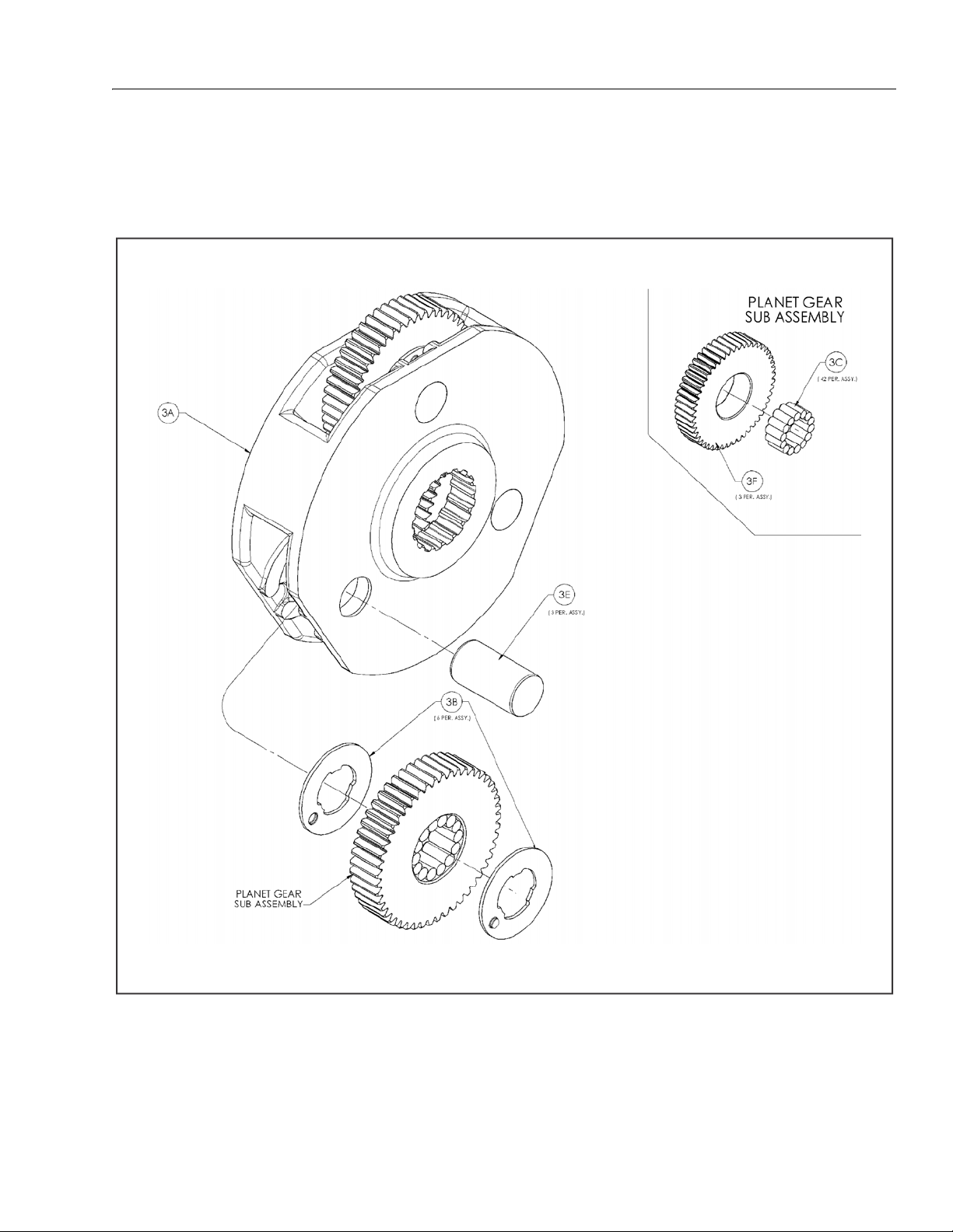
SECTION 3 - CHASSIS AND TURNTABLE
3A. Carrier 3E. Planet Shaft
3B. Thrust Washers 3F. Planet Gear
3C. Needle Bearings
Figure 3-3. Input Carrier Disassembly
Input Carrier Disassembly
1. Place Carrier (3A) on a press with spline end up. Drive
Planet Shaft (3E) out of Carrier (3A).
2. Slide Planet Gear (3F) and two Thrust Washers (3B) out
of Carrier (3A).
3. Remove 14 needle Bearings (3C) from bore of Planet
Gear (3F).
4. Repeat steps 1 through 3 for two remaining planet
gears.
3121181 – JLG Lift – 3-5
Page 48

SECTION 3 - CHASSIS AND TURNTABLE
4G. Roll Pin 4J. Thrust Washer 4B. Thrust Washers 4F. Planet Gear
4H. Thrust Washer 4K. Retaining Ring 4C. Needle Bearings
4I. Spring 4A. Carrier 4E. Planet Shaft
Figure 3-4. Output Carrier Disassembly
Output Carrier Disassembly
1. Using a small diameter punch, Drive Roll Pin (4G) which
holds Planet Shaft (4E) in Carrier (4A) into Planet Shaft
(4E) until it bottoms.
NOTE: Make sure Roll Pin has bottomed. Otherwise, damage to
carrier could occur when Planet Shaft is removed.
2. Remove Planet Shaft (4E) from Carrier (4A). Use a small
punch to remove Roll Pin (4G) from Planet Shaft (4E).
3. Slide Planet Gear (4F) and two Thrust Washers (4B) out
of Carrier (4A).
4. Remove 15 needle Bearings (4C) from bore of Planet
Gear (4F).
5. Repeat steps 1 through 4 for two remaining planet
gears.
6. Remove Thrust Washer (4H) from Carrier (4A).
7. Using retaining ring pliers, remove Retaining Ring (4K)
from Carrier (4A). Pull Thrust Washer (4J) and Spring (4I)
out of Carrier (4A).
3-6 – JLG Lift – 3121181
Page 49

SECTION 3 - CHASSIS AND TURNTABLE
1B. Seal 1D. Bearing Cone 1F. Bearing Spacer 1H. Wheel Stud
1C. Bearing Cups 1E. Housing 1G. Retaining Ring
Figure 3-5. Housing-Spindle Disassembly
Housing-Spindle Disassembly
1. Place unit on bench with Spindle (1A) end down.
EYE PROTECTION MUST BE WORN WHILE PERFORMING THE NEXT STEP IN
THIS PROCEDURE.
2. Using retaining ring pliers, remove Retaining Ring (1G)
from groove in Spindle (1A).
3. Remove Bearing Spacer (1F) from top of Bearing Cone
(1D).
4. While supporting the unit on Housing (1E) flange, press
Spindle (1A) out of Housing (1E). The Seal (1B) and “B”
position Bearing Cone (1D) should come out of Housing
(1E) with Spindle (1A).
5. Remove “A” position Bearing Cone (1D) from Bearing
Cup (1D) in Housing (1E).
6. Lift Housing (1E) off of Spindle (1A).
7. If necessary, press Studs (1N) out of Housing (1E). Locate
Housing (1E) on Seal (1B) end.
8. Remove “B” position Bearing Cone (1D) from Spindle
(1A).
9. Remove Seal (1B) from the Spindle (1A).
10. Using a soft steel rod, knock both Bearing Cups (1C) out
of Housing (1E)
3121181 – JLG Lift – 3-7
Page 50

SECTION 3 - CHASSIS AND TURNTABLE
1-A. Spindle 2-2. O-ring 2-5. Back-up Ring 2-8. Piston 2-11. Capscrew
12. Pressure Plug 2-3. Back-up Ring 2-6. Internal Circlip 2-9. Stator 2-12. Rotor
2-1. Internal Circlip 2-4. O-ring 2-7. End Plate 2-10. Spacer 2-13. Compression Spring
Figure 3-6. Spindle Brake Disassembly
Spindle-Brake Disassembly
NOTE: This procedure applies only to units with integral input
brake (2).
NOTE: For this procedure, use the Brake Assembly Drawing, which
will show the proper balloon numbers for the individual
brake components. In the following instructions, if the
number has a “-” between two numbers, it refers to the
Brake Assembly Drawing only and NOT the Torque Hub
Assembly Drawing.
NOTE: The Pressure Plug (12) requires a special tool for installa-
tion. It is not recommended to remove this plug unless it is
leaking. The plug is called a Koenig Expander. The installation tool is not supplied by Fairfield manufacturing, but
can be supplied by the manufacturer of the Koenig
Expander, Sherex Industries, or one of their distributors.
3-8 – JLG Lift – 3121181
Page 51

EYE PROTECTION MUST BE WORN WHILE PERFORMING THE STEPS 1-3 IN THIS
PROCEDURE.
SECTION 3 - CHASSIS AND TURNTABLE
NOTE: The last roller installed must be installed end wise. That is,
the end of the last roller must be placed in between the
ends of the two rollers that form the space, and then slid,
parallel to the other rollers, into place.
1. Compress the Compression Springs (2-13) by installing a
minimum of three M4 x 16mm Socket Head Cap Screws
(2-11) equally spaced through End Plate (2-7) and into
Piston (2-8) and tightening incrementally until spring
force has been taken off of the Retaining Ring (2-6).
2. Using a small pry bar or screwdriver, pry one end of the
Retaining Ring (2-6) out of the groove in Spindle (1A),
then, using pliers, pull Retaining Ring (2-6) the rest of
the way out of the groove.
3. Back Socket Head Cap Screws (2-11) incrementally out
of Piston (2-8) until spring force is relieved from the End
Plate (2-7).
4. Remove Socket Head Cap Screws (2-11) and End Plate
(2-7) from brake cavity in Spindle.
5. Remove Compression Springs (2-13) from Piston (2-8).
EYE PROTECTION MUST BE WORN WHILE PERFORMING THE NEXT STEP IN
THIS PROCEDURE.
6. Using an air hose, slowly and carefully pressurize the
brake port in the Spindle (1A) until the Piston (2-8)
comes out of piston bore of Spindle (1A), Then pull the
Piston (2-8) the rest of the way out of the Spindle (1A) by
hand.
7. Remove Backup Rings (2-3) & (2-5) and O-rings (2-2) &
(2-4) from Piston (2-8).
8. Remove Rotors (2-12) and Stators (2-9) from Spindle
(1A).
EYE PROTECTION MUST BE WORN WHILE PERFORMING THE NEXT STEP IN
THIS PROCEDURE.
9. Invert Spindle (1A) and, using retaining ring pliers,
remove Retaining Ring (2-1).
10. Remove Spacer (2-10) from Spindle.
Input Carrier Sub-Assembly
1. Apply a liberal coat of grease to the bore of one Input
Planet Gear (3F).
3. Set Carrier (3A) in an upright position.
4. Insert a Planet Shaft (3E) into the planet shaft hole in the
end of the Carrier (3A) opposite the splined end.
5. Place one Thrust Washer (3B) onto the end of Planet
Shaft (3E). Make sure the flat faces towards the inside of
the carrier and make sure the button fits in the pocket
inside the Carrier (3A).
6. Place one more Thrust Washer (3B) into the Carrier (3A).
Align the Thrust Washer (3B) in the same manner
described in Step 5.
NOTE: Some grease may need to be applied to the Thrust Washers
(3B) to hold them in place while installing the planet gear.
Instead of using grease, washers can be inserted from the
ID of the carrier for buttons to fit in pockets of the carrier.
7. Following the thrust washers, place Planet Gear (3F)
with needle rollers, into the Carrier (3A) between the
Thrust Washers (3B).
8. Push the Planet Shaft (3E) through the Planet Gear (3F)
and the other Thrust Washer (3B) until it touches the
other side of the Carrier (3A).
SAFETY GLASSES MUST BE WORN DURING THE NEXT STEP.
9. Press the Planet Shaft (3E) until it is pressed to the
appropriate depth.
NOTE: If planet shaft locating tooling is not available, press lightly
on Planet Shaft (3E) and make sure not to press Planet
Shaft (3E) through the small shoulder in Carrier (3A). This
shoulder is intended to keep the planet pin from working
loose in that direction during proper operation of the unit.
It is NOT intended to keep the planet pin from being
pressed through the carrier.
10. On the side of the Carrier (3A) where the Planet Shaft
(3E) was inserted, stake the Carrier (3A) in 3 places using
a punch and a hammer around the Planet Shaft (3E) to
assure the shaft stays in place during operation of the
unit.
11. Repeat Steps 1 through 10 for the installation of the two
remaining Planet Gears (3F).
2. Line the inside of the Planet Gear (3F) with 14 Needle
Rollers (3C).
3121181 – JLG Lift – 3-9
Page 52

SECTION 3 - CHASSIS AND TURNTABLE
3A. Carrier 3E. Planet Shaft
3B. Thrust Washers 3F. Planet Gear
3C. Needle Bearings
Figure 3-7. Input Carrier Sub-Assembly
3-10 – JLG Lift – 3121181
Page 53

SECTION 3 - CHASSIS AND TURNTABLE
Output Carrier Sub-Assembly
1. Place Spring (4I) into the deep counterbore of the Output Carrier (4A).
2. Place Washer (4J) on top of Spring (4I).
SAFETY GLASSES MUST BE WORN DURING THE NEXT STEP.
3. With Retaining Ring (4K) installed on snap ring pliers,
place on top of Washer (4J) and compress Spring (4I)
until Retaining Ring (4K) is seated completely in groove.
4. Apply a liberal coat of grease to the bore of one Output
Planet Gear (4F).
5. Line the inside of the Planet Gear (4F) with 15 Needle
Rollers (4C).
NOTE: The last roller installed must be installed end wise. That is,
the end of the last roller must be placed in between the
ends of the two rollers that form the space, and then slid,
parallel to the other rollers, into place.
6. Place Thrust Washer (4H) into the shallow counterbore
of the Output Carrier (4A).
7. Set Carrier (4A) in an upright position.
8. Insert a Planet Shaft (4E) into one of the planet shaft
holes on the Carrier (4A). The end of the planet shaft
that does NOT have the roll pin hole should be inserted
in the carrier FIRST.
9. Place one Thrust Washer (4B) onto the end of Planet
Shaft (4E). Make sure the flat faces towards the inside of
the carrier and make sure the button fits in the pocket
inside the Carrier (4A).
10. Following the thrust washer, place Planet Gear (4F) with
needle rollers, onto Planet Shaft (4E).
11. Following the planet gear, place one more Thrust
Washer (4B) onto Planet Shaft (4E). Align the Thrust
Washer (4B) in the same manner described in Step 6.
12. Now insert Planet Shaft (4E) through the opposite
planet shaft hole on Carrier (4A). Use an alignment
punch or similar tool to align the roll pin holes on Carrier
(4A) and Planet Shaft (4E).
SAFETY GLASSES MUST BE WORN DURING THE NEXT STEP.
13. Drive Roll Pin (4G) down into the aligned roll pin holes.
Pin should be flush with OD of carrier.
14. Repeat Steps 4,5, & 8-13 for the installation of the two
remaining Planet Gears (4F).
3121181 – JLG Lift – 3-11
Page 54

SECTION 3 - CHASSIS AND TURNTABLE
4A. Output Carrier 4E. Planet Shaft 4H. Thrust Washer 4K. Retaining Ring
4B. Thrust Washer 4F. Planet Gear 4I. Spring
4C. Needle Rollers 4G. Roll Pin 4J. Washer
Figure 3-8. Input Carrier Sub-Assembly
3-12 – JLG Lift – 3121181
Page 55

SECTION 3 - CHASSIS AND TURNTABLE
Spindle-Brake Sub-Assembly
NOTE: This procedure applies only to units with integral input
brake (2).
NOTE: For this procedure, use the Brake Assembly Drawing, which
will show the proper balloon numbers for individual brake
components. In the following instructions, if the number
has a “-” between two numbers, it refers to the Brake
Assembly Drawing only and NOT the Torque Hub Assembly
Drawing.
NOTE: The Pressure Plug (12) requires a special tool for installa-
tion. It is not recommended to remove this plug unless it is
leaking. The plug is called a Koenig Expander. The installation tool is not supplied by Fairfield manufacturing, but
can be supplied by the manufacturer of the Koenig
Expander, Sherex Industries, or one of their distributors.
1. Install Pressure Plug (12) into Spindle (1A) using following procedure:
• Clean hole in spindle using appropriate Loctite spray
• Dip collar of plug in Loctite 290 or 680 (keep unplugged
portion of hole free of Loctite)
• Using appropriate tool, install plug flush with surface of
spindle
SAFETY GLASSES MUST BE WORN DURING THE NEXT STEP.
9. Grease the large O-Ring (2-2) and install in the largediameter groove at the bottom of the Piston (2-8), on
top of the large Backup Ring (2-3).
10. Grease the small O-Ring (2-5) and install in the smalldiameter groove near the top of the Piston (2-8). Make
sure the O-Ring is seated on the bottom of the groove.
11. Grease the small Backup Ring (2-4) and install in the
small-diameter groove near the top of the Piston (2-8),
on top of the small O-Ring (2-5).
NOTE: If piston comes pre-assembled with shipping bolts (2-11),
skip to Step 15.
12. Insert Piston (2-8) into Spindle (1A) until it contacts the
Stator (2-9).
13. Insert appropriate number of Springs (2-13) into Piston
(2-8) counterbore. Use brake spring chart below and a
bill of materials for your particular model number to
determine number of springs.
BRAKE
CODE
A 902337 12
B 902341 10
C 902342 8
D 902343 6
E 902345 9
BRAKE P/N
NUMBER
OF SPRINGS
2. Place Spindle (1A) such that the splined end is facing
down. Using appropriate tool (See back of manual),
install Retaining Ring (2-1) into the spindle groove
within the splines.
3. Place Washer (2-10) on top of Retaining Ring (2-1).
4. Place Stator (2-9) on top of Washer (2-10).
5. Place Rotor (2-12) on top of Stator (2-9).
6. Repeat steps 3 & 4 until there are a total of 8 Stators (2-9)
and 7 Rotors (2-12) installed.
7. Place Piston (2-8) such that the smaller O.D. end is facing
upward.
8. Grease the large Backup Ring (2-3) and install in the
large-diameter groove at the bottom of the Piston (2-8).
14. Place Pressure Plate (2-7) on top of Springs (2-13).
SAFETY GLASSES MUST BE WORN DURING THE NEXT TWO STEPS.
15. Using snap ring pliers, install Retaining Ring (2-6) into
groove in Spindle (1A) and on top of Pressure Plate (2-7).
Make sure that Retaining Ring (2-6) is seated properly in
the groove.
16. Remove Shipping Bolts (2-11) in brake pressure plate to
release springs in brake. Before removing bolts, use the
Coupling (9) (See Assembly Drawing at back of manual)
to center and align the Brake Rotors (2-12) with the Spindle (1A).
3121181 – JLG Lift – 3-13
Page 56

SECTION 3 - CHASSIS AND TURNTABLE
1-A. Spindle 2-3. Back-up Ring 2-7. End Plate 2-11. Capscrew
12. Pressure Plug 2-4. O-ring 2-8. Piston 2-12. Rotor
2-1. Internal Circlip 2-5. Back-up Ring 2-9. Stator 2-13. Compression Spring
2-2. O-ring 2-6. Internal Circlip 2-10. Spacer
Figure 3-9. Spindle Brake Sub-Assembly
3-14 – JLG Lift – 3121181
Page 57

SECTION 3 - CHASSIS AND TURNTABLE
Housing-Spindle Sub-Assembly
NOTE: Spray a light film of oil on all component parts during
assembly.
SAFETY GLASSES MUST BE WORN DURING THE ENTIRE HOUSING-SPINDLE
SUBASSEMBLY.
1. Press Bearing Cup (1C), position A, into Housing (1E)
using appropriate pressing tool (See back of manual).
2. Turn Housing (1E) over and place into pressing base.
Press nine Studs (1H) into Housing (1E).
NOTE: Use enough pressure to press in studs. Don t use excessively
high pressure to press in studs or Housing may crack. Make
sure head of stud contacts face of flange on Housing.
NOTE: Spray a generous amount of oil on bearings during instal-
lation.
3. Press Bearing Cup (1C), position "B", into Housing (1E)
using “B” Bearing Cone pressing tool (see back of manual).
4. Place Bearing Cone (1D), into Bearing Cup (1C), position
"B".
5. Grease Seal (1B) lip and press seal into Housing (1E)
using seal pressing tool (see back of manual) until seal is
flush with end of Housing.
6. Turn Housing (1E) over and lower onto Spindle (1A).
7. Install Bearing Cone (1D) into Bearing Cup (1C), position
"A". and lightly press on Bearing Cup using the “A” Bearing Cone pressing tool (see back of manual) while rotating Housing (1E) in both directions to seat bearings.
Integral Brake Check
1. Using appropriate fittings, connect hydraulic line from
hand pump to brake port.
2. Check brake is set by trying to rotate Input Shaft (7). This
can be accomplished by installing an appropriate tool
(any tool that can locate on splines of Input Coupling (9),
such as a mating splined shaft) into Input Coupling (9)
3. Bleed brake. Increase hydraulic pressure gradually while
trying to rotate input until brake just starts to release.
Note this pressure. Make sure pressure falls into the
appropriate range below.
BRAKE
CODE
A 902337 185-230
B 902341 155-192
C 902342 125-155
D 902343 93-115
E 902345 132-172
4. Increase pressure to 3,000 psi and hold for 30 seconds to
NOTE: Make sure brake re-engages when pressure is released.
NOTE: When done, make sure Input Coupling (9) is centered in
BRAKE P/N
check for leaks. Repair leaks if necessary.
Spindle (1A) to make installation of motor possible without
release of brake.
JUST RELEASE
PRESSURE RANGE (psi)
8. Place Bearing Spacer (1F) on top of Bearing Cone (1D).
9. Using retaining ring pliers, install Retaining Ring (1G)
into Spindle (1A) groove. Make sure ring is completely
seated in groove.
NOTE: Extra bearing pre-load caused by pressing “A” Bearing
Cone (1D) must be removed. This should be done by placing a flat piece of steel or a pressing tool on end of spindle,
then lightly striking the tool with a piece of barstock. This
should be adequate to remove any additional bearing preload.
3121181 – JLG Lift – 3-15
Page 58

SECTION 3 - CHASSIS AND TURNTABLE
1B. Seal 1D. Bearing Cone 1F. Bearing Spacer 1H. Wheel Stud
1C. Bearing Cups 1E. Housing 1G. Retaining Ring
Figure 3-10. Housing-Spindle Disassembly
3-16 – JLG Lift – 3121181
Page 59

SECTION 3 - CHASSIS AND TURNTABLE
7. Input Shaft 8. Output Sun Gear 17. Input Sun Gear
Figure 3-11. Main Assembly Drawing 1
Main Assembly
NOTE: All components should receive a generous amount of lubri-
cant oil as they are being assembled.
1. Place Housing-Spindle Sub-Assembly on bench with
Spindle (1A) side down.
2. Place Output Carrier Sub-Assembly into Housing (1E)
and onto Spindle (1A).
3. Insert larger diameter splined end of Input Shaft (7)
through bore of Output Carrier Sub Assembly (4A) until
shoulder of Input Shaft (7) contacts Thrust Washer (4J)
(See assembly drawing at back of manual).
4. With modified spline end facing up, place Output Sun
Gear (8) into mesh with planet gears from Output Carrier
Sub-Assembly (4A).
5. Place Input Carrier Sub-Assembly (3A) onto Output Sun
Gear (8) splines.
6. Grease O-Ring (19) and insert into groove in Cover SubAssembly (6).
7. Install Cover Sub-Assembly (6) onto Housing (1E) and
install twelve Bolts (14) into Cover (6). Torque bolts to
70-80 in-lbs.
8. Attach ID Tag (15) onto unit. If Cover has knobs as part of
the cover, peen top of each knob to form a head to hold
on the Tag. If cover has no such knobs, use drive screws.
9. Check disconnect, roll and leak check unit, leak check
brake, check brake release pressure.
3121181 – JLG Lift – 3-17
Page 60

SECTION 3 - CHASSIS AND TURNTABLE
6. Cover 10. Thrust Spacer 19. O-ring
9. Input Coupling 14. Cover Bolts
Figure 3-12. Main Assembly Drawing 2
3-18 – JLG Lift – 3121181
Page 61

SECTION 3 - CHASSIS AND TURNTABLE
Figure 3-13. Assembly Drawing - Without Integral Input Brake - Sheet 1 of 2
3121181 – JLG Lift – 3-19
Page 62

SECTION 3 - CHASSIS AND TURNTABLE
1A Spindle
1G Retaining Ring - Ext
12 Pressure Plug
16 O-ring Pipe Plug
1F Thrust Washer
1E Housing/Ring Gear
1N Stud
1C Tapered Bearing - Cup
1D Tapered Bearing - Cone
1B Lip Seal
3A Carrier
3F Planet Gear
3E Planet Shaft
3C Needle Bearing
3B Thrust Washer
4A Carrier
4F Planet Gear
4E Planet Shaft
4C Needle Bearing
4I Spring
4K Retaining Ring - Int
4G Roll Pin
4B Thrust Washer
4H Thrust Washer
4J Thrust Washer
17 Sun Gear
8Sun Gear
7Input Shaft
9Coupling
6 Cover Subassembly
10 Thrust Spacer
15 Id Plate
14 12 Pt Flange Bolt
19 O-ring
Figure 3-14. Assembly Drawing - Without Integral Input Brake - Sheet 2 of 2
3-20 – JLG Lift – 3121181
Page 63

SECTION 3 - CHASSIS AND TURNTABLE
Figure 3-15. Assembly Drawing - With Integral Input Brake - Sheet 1 of 2
3121181 – JLG Lift – 3-21
Page 64

SECTION 3 - CHASSIS AND TURNTABLE
1A Spindle
2 Input Brake
1G Retaining Ring - Ext
12 Pressure Plug
16 O-ring Pipe Plug
1F Thrust Washer
1E Housing/Ring Gear
1N Stud
1C Tapered Bearing - Cup
1D Tapered Bearing - Cone
1B Lip Seal
3A Carrier
3F Planet Gear
3E Planet Shaft
3C Needle Bearing
3B Thrust Washer
4A Carrier
4F Planet Gear
4E Planet Shaft
4C Needle Bearing
4I Spring
4K Retaining Ring - Int
4G Roll Pin
4B Thrust Washer
4H Thrust Washer
4J Thrust Washer
17 Sun Gear
8Sun Gear
7Input Shaft
9 Coupling
6 Cover Subassembly
10 Thrust Spacer
15 Id Plate
14 12 Pt Flange Bolt
19 O-ring
Figure 3-16. Assembly Drawing - With Integral Input Brake - Sheet 2 of 2
3-22 – JLG Lift – 3121181
Page 65

SECTION 3 - CHASSIS AND TURNTABLE
Figure 3-17. Assembly Tools - Bearing Cone Pressing - “B” Bearing
3121181 – JLG Lift – 3-23
Page 66

SECTION 3 - CHASSIS AND TURNTABLE
Figure 3-18. Assembly Tools - Bearing Cone Pressing - “A” Bearing
3-24 – JLG Lift – 3121181
Page 67

SECTION 3 - CHASSIS AND TURNTABLE
Figure 3-19. Assembly Tools - Bearing Cup Pressing - “A” & “B” Bearings
3121181 – JLG Lift – 3-25
Page 68

SECTION 3 - CHASSIS AND TURNTABLE
Figure 3-20. Assembly Tools - Seal Pressing
3-26 – JLG Lift – 3121181
Page 69

SECTION 3 - CHASSIS AND TURNTABLE
Figure 3-21. Assembly Tools - Spacer - Brake Disc Installation
3121181 – JLG Lift – 3-27
Page 70

SECTION 3 - CHASSIS AND TURNTABLE
Figure 3-22. Assembly Tools - Brake Retaining Ring Installation
3-28 – JLG Lift – 3121181
Page 71

SECTION 3 - CHASSIS AND TURNTABLE
3.3 TORQUE HUB (MACHINES BUILT AFTER S/N
1300000064)
Roll and Leak Testing
Always roll and leak test Torque-Hubs after assembly to make
sure that the unit’s gears and sealants are working properly.
The following information briefly outlines what to look for
when performing these tests.
ROLL TEST
The purpose of a roll test is to determine if the unit’s gears are
rotating freely and properly. You should be able to rotate the
gears in your unit by applying a constant
checker. If you feel more drag in the gears only at certain
points, then the gears are not rolling freely and you should
examine them for improper installation or defects. Some gear
packages roll with more difficulty than others. Do not be concerned if the gears in your unit seem to roll hard as long as
they roll with consistency
LEAK TEST
The purpose of a leak test is to make sure the unit is air tight.
You can tell if your unit has a leak if the pressure gauge reading on your air checker starts to fall once you have pressurized
the unit. Leaks will most likely occur at the main seal or wherever o-rings or gaskets are located. Usually you can detect the
exact location of a leak by brushing a soap and water solution
around the main seal and where o-rings or gaskets meet the
exterior of the unit, then checking for air bubbles. If you detect
a leak in a seal, o-ring, or gasket, replace the part immediately.
force to the roll
Tightening and Torquing Bolts
Oil Information
1. 1. TYPE – EP90
On normal applications, use EP90. On applications
where the lubricant must meet special requirements,
the O.E.M should be able to recommend a suitable substitute.
2. OIL TEMPERATURE
Continuous – 160° F [70° C] Intermittent – 200° F [95° C]
3. OIL CHANGE
Initial – After 50 hours or 50,000 revolutions of operation. Subsequent – After 1000 hours or (1) year, whichever comes first.
NOTE: Higher temperatures make it necessary to change oil more
frequently.
4. OIL FILL LEVEL AND VOLUME
Unit mounted horizontal – half full. (See Diagram A.)
Approximate volume - 17 oz. [0.5 1tr)
Main Disassembly for ”B” Drives
1. 1. Turn hub (1G) over onto its side, Remove coupling (14)
from the wide end of spindle (1A).
2. Mark location of shoulder bolt holes on out- side of ring
gear and hub for easy re-alignment when rebuilding.
Remove the four shoulder bolts (13) and twelve bolts
(12) from cover (6).
3. Remove the sixteen flat washers (16) from cover (6).
4. Lift cover sub-assembly (6) off of ring gear (4), and set
cover on table, interior side facing up.
If you use an air impact wrench to tighten bolts, take extreme
care to ensure that you do NOT tighten the bolts beyond their
indicated torque specification. Never
tighten shoulder bolts. Always
hand.
The following steps describe the proper procedure for tightening and torquing bolts or socket head capscrews in a bolt circle.
1. Tighten (but do not torque) bolt ”A” until snug.
2. Go to the opposite side of the bolt circle and tighten
bolt ”B” until equally snug.
3. Continue around the bolt circle and tighten the remaining bolts.
4. Now use a torque wrench to apply the specified torque
to bolt ”A”.
5. Continue around the bolt circle and apply an equal
torque to the remaining bolts.
use an impact wrench to
tighten all shoulder bolts by
CAUTION: BEWARE OF SHARP EDGES IN THE COUNTERBORE WHEN YOU
REMOVE THE O-RING.
5. Remove o-ring (5) from the counterbore around the
edge of cover (6A). Discard the o-ring.
NOTE: If o-ring is not in the cover counter- bore, it is in the ring
gear counterbore. Remove it from the hub and discard it.
6. Remove thrust washer (11) from the counter- bore in top
of carrier (3A).
7. Remove input gear (8) from the middle of carrier subassembly (3).
8. Lift ring gear (4) off of hub (1G).
9. Lift carrier sub-assembly (3) out of hub (1G).
10. Remove thrust spacer (9) from input shaft (7) in the middle of spindle (1A).
11. Lift input shaft sub-assembly (7) out of middle of spindle
(1A), and stand input shaft (7A) on its splined end.
3121181 – JLG Lift – 3-29
Page 72

SECTION 3 - CHASSIS AND TURNTABLE
WEAR SAFETY GLASSES DURING THIS STEP, AND BE AWARE THAT SPRING AND
SPACERS COMPRESSED BY RETAINING RING MAY POP SUDDENLY OFF SHAFT
WHEN YOU REMOVE THE RETAINING RING.
12. Using retaining ring pliers, remove retaining ring (7B)
from the groove on input shaft (7A).
13. Remove one spacer (7D), one spring (7C), and other
spacer (7D) from input shaft (7A).
14. Remove thrust washer (11) from around spindle (1A).
15. Lift internal gear (2) out of hub (1G).
BEWARE OF SHARP EDGES IN COUNTERBORE WHEN YOU REMOVE THE ORING.
16. Remove o-ring (5) from the counterbore in hub (1G). Discard the o-ring.
17. At this point the main disassembly for ”B” drives is complete.
Hub-Spindle Disassembly
NOTE: Start with large end of hub facing up, large end of spindle
facing down.
WEAR SAFETY GLASSES DURING THIS STEP.
1. Remove retaining ring (1I) from around spindle (1A) ia
hub (1G).
2. Remove spacer (1H) from around spindle (1A) in hub
(1G).
3. Set hub (1G), small end/spindle facing down, up on
something that will support the hub’s flange while it lifts
hub up so spindle is not resting on anything. Carefully
press or hammer spindle (1A) down out of hub (1G).
NOTE: If seal (1B) and bearing cone (1D) come out of hub and rest
on spindle, remove these parts from the spindle and set
them aside. Discard the seal.
4. If seal and bearing cone did not come out of small end
of hub (1G) when you pressed spindle out of hub,
remove seal (1B) and bearing cone (1D) from the small
end of hub (1G). Discard the seal.
5. Bearing cone (1F) should be lying loose in wide end of
hub (1G). Remove bearing cone (1F) from inside hub
(1G).
NOTE: If you use a punch and hammer, make sure you do not
strike counterbore with punch when you remove bearing
cup.
6. Remove bearing cup (1C) from the counterbore in the
small end of hub (1G).
NOTE: If you use a punch and hammer, make sure you do not
strike the counterbore with the punch when you remove
the bearing cup.
7. Turn hub (1G) over and lift it out of the flange-support.
Remove bearing cup (1E) from the counterbore in the
wide end of hub (1G).
8. Turn hub (1G) over onto its small end. Remove two pipe
plugs (1J) from the two pipe plug holes in the side of
hub (1G).
NOTE: If your unit does not have studs, skip this step:
9. Press nine studs (1N) out of stud holes in hub (1G).
10. At this point hub-spindle disassembly is complete.
Cover Disassembly
1. Remove two bolts (6C) holding disconnect cap (6D) to
cover (6A).
2. Remove disconnect cap (6D) from on top of cover cap
(6B) and cover (6A).
3. Remove the two bolts (6C) holding cover cap (6B) to
cover (6A).
4. Remove cover cap (6B) from cover (6A).
5. Remove disconnect rod (6K) from cover cap (6B).
6. Pry o-ring (6F) out of the groove inside cover cap (6B).
Discard the o-ring.
7. Remove o-ring (6G) from the flange of cover cap (6B).
Discard the o-ring.
8. Remove pipe plug (6H) from cover (6A).
9. At this point the cover disassembly is complete.
Carrier Disassembly
NOTE: When you remove needle rollers from cluster gears, discard
old needle rollers and use new ones during re-assembly.
1. Using a punch and hammer, drive roll pin (3G) into
planet shaft (3E).
NOTE: If you don’t drive the roll pin all the way into the planet
shaft t, you could damage the carrier when you remove the
planet shaft from the carrier.
2. Using a punch and hammer, drive planet shaft (3E) out
of the planet shaft t hole in carrier housing (3A).
3. When you remove planet shaft (3E) from carrier housing,
one thrust washer (38), one cluster gear (3F), and one
more thrust washer (3B) will come off of the planet shaft
and come to rest inside the carrier. Remove these parts
from inside the carrier.
3-30 – JLG Lift – 3121181
Page 73

SECTION 3 - CHASSIS AND TURNTABLE
4. Remove 16 needle rollers (3C) from inside one end of
cluster gear (3F). Discard the needle rollers.
5. Remove one spacer (3D) from inside cluster gear (3F).
6. Remove the remaining 16 needle rollers (3C) from the
other side of cluster gear (3F). Discard the needle rollers.
7. Repeat steps 1-6 to remove and disassemble the two
remaining cluster gears.
8. At this point the carrier disassembly is complete.
Carrier Assembly
1. Apply grease to inside of one cluster gear (3F) and line
one half of cluster gear with 16 needle rollers (3C).
3. Line remaining half of cluster gear (3F) with 16 needle
rollers.
4. Set carrier housing (3A) on table, sideways. Insert a
planet shaft (3E), roll pin hole last, in one of planet shaft
holes from roll-pin-holed side of carrier housing (3A).
2. Place one spacer (3D) inside cluster gear (3F) so that it
rests on top of the needle rollers.
5. Place one thrust washer (3B) onto the end of planet
shaft (3E) inside carrier. Fit tang of thrust washer into the
slot on the inside edge of the planet shaft hole.
3121181 – JLG Lift – 3-31
Page 74

SECTION 3 - CHASSIS AND TURNTABLE
6. Following thrust washer, place cluster gear (3F), large
end toward roll pin hole in carrier housing, on planet
shaft (3E).
7. Following cluster gear, place one more thrust washer
(3B) on planet shaft (3E) through opposite planet shaft
hole in carrier housing (3A).
9. Drive roll pin (3G) down in aligned roll pin holes in carrier housing (3A) and planet shaft (3E).
10. Repeat steps 1 thru 9 to assemble and install remaining
cluster gears.
11. At this point carrier sub-assembly is complete.
8. Use an alignment punch or similar tool to align roll pin
holes in carrier housing (3A) and planet shaft (3E).
3-32 – JLG Lift – 3121181
Page 75

SECTION 3 - CHASSIS AND TURNTABLE
Cover Sub-Assembly
1. Using the disconnect rod, push O-ring (6F) in groove
inside cover cap (6B).
2. Place O-ring (6G) on cover cap (6B) so that it rests
against flange of cover cap.
4. Set cover (6A) on table, exterior side up. Place cover cap
(6B) on cover (6A), aligning pipe plug hole in cover cap
over pipe plug hole in cover.
5. Place two cover cap bolts (6C) in any two bolt hoes that
are 180° apart on cover cap (6B) and tighten bolts.
3. Insert disconnect rod (6E) in cover cap (6B).
6. Using a torque wrench, apply 36 to 49 in-lb (4 to 5 Nm)
of torque to both bolts (6C).
3121181 – JLG Lift – 3-33
Page 76

SECTION 3 - CHASSIS AND TURNTABLE
7. With large end down, place disconnect cap (6D) on
cover cap (6B), aligning pipe plug hole in disconnect cap
over pipe plug hole in cover cap.
8. Place two remaining bolts (6C) in bolt holes in disconnect cap (6D). Tighten bolts.
10. Apply a light coat of "Never-Seize" to pipe plug (6H) and
tighten it in pipe plug hole in cover (6A).
Hub-Spindle Sub-Assembly
NOTE: Make sure cup is square with counterbore before pressing.
1. Set hub (1G) on large end. Press bearing cup (1C) in
counterbore in small end of hub (1G).
9. Using a torque wrench, apply 36 to 49 in-lb (4 to 5 Nm)
of torque to both bolts (6C).
2. Press nine studs (1N) in stud holes in hub (1G).
3-34 – JLG Lift – 3121181
Page 77

SECTION 3 - CHASSIS AND TURNTABLE
3. Apply a light coat of "Never-Seize" to two pipe plugs (1J)
and tighten them into two pipe plug holes in side of
hub (1G).
NOTE: Make sure cup is square with counterbore before pressing.
4. Turn hub (1G) over onto its small end. Press bearing cup
(1E) in counterbore in deep end of hub (1G).
6. Press seal (1B) in small end of hub (1G).
7. Oil spindle, then lower hub (1G), small end down, onto
spindle (1A).
5. Set hub (1G) on its large end. Place bearing cone (1D) in
bearing cup (1C).
8. Press bearing cone (1F) on spindle (1A) in hub (1G).
3121181 – JLG Lift – 3-35
Page 78

SECTION 3 - CHASSIS AND TURNTABLE
9. Place spacer (1H) on spindle (1A) in hub (1G).
NOTE: Make sure retaining ring is securely seated in groove.
10. Place retaining ring (1I) over spacer onto spindle (1A) in
hub (1G).
Main Assembly
BEWARE OF SHARP EDGES IN COUNTERBORE WHEN INSTALLING THE O-RING
1. Grease O-ring (5) and place it in hub counterbore (1G).
NOTE: O-ring may be stretched or pinched together to make it fit
counterbore.
2. Oil all exposed surfaces inside hub (1G).
11. At this point hub-spindle sub-assembly is complete.
Place internal gear (2) in hub (1G) so its internal splines
mesh with external splines of spindle (1A). Oil internal
gear (2).
3-36 – JLG Lift – 3121181
Page 79

SECTION 3 - CHASSIS AND TURNTABLE
3. Place thrust washer (11) around spindle (1A) so it rests
on bottom of internal gear (2).
4. Stand input shaft (7A) on its splined end. Place one
spacer (7D) on smooth end of input shaft (7A).
6. Place spacer (7D) on smooth end of input shaft (7A).
WEAR SAFETY GLASSES DURING THIS STEP, AND BE AWARE THAT SPRING AND
SPACERS, COMPRESSED BY RETAINING RING, MAY POP SUDDENLY OFF SHAFT IF
THE RING IS RELEASED BEFORE IT IS PROPERLY IN PLACE.
7. Using retaining ring pliers, insert retaining ring (7B) in
groove on input shaft (7A) by compressing spring and
spacers together.
5. Place one spring (7C) on smooth end of input shaft (7A).
8. With large splined end down, place input shaft subassembly (7) in spindle (1A).
3121181 – JLG Lift – 3-37
Page 80

SECTION 3 - CHASSIS AND TURNTABLE
Figure 3-23. Cluster Gear Punch Marks
9. Place thrust spacer (9) on input shaft (7).
10. Set carrier sub-assembly (3) on a flat work surface so
large ends of cluster gears (3F) face up. Locate punch
marks on face of each cluster gear (3F) and position
them at 12 o’clock.
12. Place carrier sub assembly (3) and ring gear (4) together
into mesh with internal gear (2). Align "X" marked shoulder bolt hole in ring gear (4) over one of the shoulder
bolt holes in the hub. Mark location of shoulder bolt
holes on outside of ring gear and hub.
NOTE: You may lift ring gear off hub to align shoulder bolt holes.
Ring gear and carrier are installed together only to keep
punch marks on the carrier in place.
13. With internal splines facing up (counterbore end facing
down), place input gear (8) into mesh with carrier subassembly (3).
11. With "X" marked side facing up, place ring gear (4)
around cluster gears (3F).
NOTE: This will hold punch marks in position while installing car-
rier into hub.
14. Oil all exposed surfaces inside hub (1G). Place thrust
washer (11) in counterbore in top of carrier.
3-38 – JLG Lift – 3121181
Page 81

BEWARE OF SHARP EDGES IN COUNTERBORE WHEN INSTALLING O-RING.
15. Set cover (6A) on table, interior side up. Grease O-ring (5)
and place it in counterbore around edge of cover (6A).
NOTE: O-ring may be stretched or pinched together to make it fit
counterbore.
SECTION 3 - CHASSIS AND TURNTABLE
18. Place shoulder bolts (13) in four shoulder bolt holes in
cover (6). Tighten by hand.
19. Place remaining 12 flat washers (16) on remaining bolt
holes in cover (6).
16. Place cover sub-assembly (6) on ring gear (4). Align pipe
plug holes according to alignment before disassembly.
17. Place four flat washers (16) on top of bolt holes in cover
sub-assembly.
20. Place 12 bolts in remaining bolt holes in cover (6) and
tighten.
3121181 – JLG Lift – 3-39
Page 82

SECTION 3 - CHASSIS AND TURNTABLE
21. Torque shoulder bolts (13) 18 to 25 ft-lb (25 to 34 Nm).
Torque bolts (12) 18 to 25 ft-lb (25 to 34 Nm).
22. Turn hub (1G) over on its side. Insert coupling (14) in the
end of spindle (1A).
24. Leak test unit at a pressure of 5 psi for 2 to 3 minutes.
25. At this point main assembly is complete.
23. Roll test unit in clockwise and counterclockwise directions. Perform same number of turns in each direction as
the ratio of the unit. The ratio is last two digits of model
number on the unit’s ID tag.
3-40 – JLG Lift – 3121181
Page 83

SECTION 3 - CHASSIS AND TURNTABLE
Tool List
The following specialized tools are used to assemble this unit.
Tool diagrams included in this manual are intended for the
customer who may wish to have a tool made. All tools exist as
one piece and must be made from mild steel All dimensions
are given in inches.
NOTE: To improve tool life, tools may be carburized and hard-
ened. If this is done, tools must be ground on all surfaces
labeled with a "G" on the tool diagram.
1. T-118126 SEAL PRESSING TOOL for SEAL (1B).
3. T-140433 ASSEMBLY PRESSING TOOL for CUP (1E)
4. T-109691 ASSEMSLY PRESSING TOOL for CONE (1F)
2. T-138903 ASSEMBLY PRESSING TOOL for CUP (1C)
* These tools are for specific seals, cups or cones. There is a
specific tool for each cup and cone.
3121181 – JLG Lift – 3-41
Page 84

SECTION 3 - CHASSIS AND TURNTABLE
Bias spring
Servo piston
Swashplate
Output
Shaft
Piston
Slipper
Cylinder
Block
Endcap
Shaft
Seal
Bearing
Minimum
Angle
Stop
Valv
e plate
Figure 3-24. Drive Motor Cross Section
1
2
3
1. Snap Ring
2. Support Washer
3. Shaft Seal
Figure 3-25. Removing Shaft Seal
3.4 RE-ALIGNING TORQUE HUB INPUT COUPLING
The following procedure applies to torque hubs with integral
brakes.
Equipment Required
1. Hydraulic power supply (hand pump) capable of producing 200 psi (13.8 bar).
2. Hydraulic fittings to adapt hydraulic supply to brake
release port on hub.
Procedure
1. Using appropriate fittings, connect a line from hydraulic
power supply to brake port.
2. Pressurize brake release port 155 to 200 psi (10.6 to 13.8
bar) to release brake.
3. Verify that the brake is released by rotating the input
coupling or hub spindle.
4. Once the brake is released, the input coupling will be
free to re-align with the drive motor.
5. Install drive motor on hub, then release hydraulic pressure at brake release port. Coupling will remain in position.
6. Disconnect the hydraulic power supply and reconnect
the line going into the brake release port.
The large diameter servo piston allows smooth acceleration
and deceleration with relatively large circuit orificing.
Shaft Seal Replacement
REMOVAL
1. Remove snap ring (1) retaining shaft seal and support
washer.
3.5 DRIVE MOTOR
Description
Drive motors are low to medium power, two-position axial piston motors incorporating an integral servo piston. They are
designed for operation in both open and closed circuit applications. The standard control is a direct acting single line
hydraulic control. The integral servo piston controls motor displacement.
Motors are spring biased to maximum displacement and
hydraulically shifted to minimum displacement. Minimum and
maximum displacement can be set with fixed internal stops.
2. Remove the support washer (2).
3. Carefully pry out shaft seal (3).
NOTE: To avoid damaging shaft during removal, install a large
sheet metal screw in chuck of a slide hammer. Drive screw
into seal surface and use slide hammer to pull seal.
4. Discard seal.
3-42 – JLG Lift – 3121181
Page 85

SECTION 3 - CHASSIS AND TURNTABLE
2
6
9
11
1
4
8
10
12
5
3
7
13
(37 Nm)
27 ft.lbs.
11/16 in
(37 Nm)
27 ft.lbs.
11/16 in
(27 Nm)
20 ft.lbs.
5/8 in
1. Plug
2. Plug
3. Plug
4. O-ring
5. O-ring
6. O-ring
7. Spring
8. Spring
9. Spring
10. Washer
11. Washer
12. Shift Spool
13. Orifice Poppet
Figure 3-26. Loop Flushing Spool
INSPECT COMPONENTS
Inspect the new seal, the motor housing seal bore, and the
sealing area on the shaft for rust, wear, and contamination.
Polish the shaft and clean the housing if necessary.
INSTALLATION
1. Cover the shaft splines with an installation sleeve to protect the shaft seal during installation.
2. Install a new shaft seal with the cupped side facing the
motor. Press seal into housing until it bottoms out. Press
evenly to avoid binding and damaging the seal.
3. Install seal support washer.
4. Install snap ring.
5. Remove the installation sleeve.
Loop Flushing Valve
REMOVAL
1. Using a 11/16 in internal hex wrench remove plug (1)
and (2).
5. Remove spring retaining washers (10 and 11).
6. Remove shift spool (12).
7. Remove orifice poppet (13).
INSPECT COMPONENTS
Inspect new O-rings and the sealing area for rust, wear, or contamination. Also check springs and poppet for wear.
INSTALLATION
1. Install orifice poppet (13).
2. Install shift spool (12).
3. Install spring retaining washers onto springs (10 and 11).
4. Carefully install centering springs (7, 8, and 9).
5. Install new O-rings (6, 4, and 5).
6. Using a 1/4 in hex wrench torque plug (3) to 20 ft. lbs.
(27 Nm).
7. Using a 11/16 in internal hex, torque plugs (2 and 1) to
27 ft.lbs. (37 Nm).
2. Using a 1/4 in hex wrench remove plug (3).
3. Remove O-rings (4, 5, and 6).
4. Using pliers, remove centering springs (7, 8, and 9).
3121181 – JLG Lift – 3-43
Page 86

SECTION 3 - CHASSIS AND TURNTABLE
Troubleshooting
Table 3-2. Excessive Noise and/or Vibration
Item Description Action
Check oil level in reservoir and oil
supply to the motor.
Insufficient hydraulic fluid could lead to cavitation that would cause system noise.
Fill the reservoir to the proper level and ensure that oil supply to the motor
is adequate and the lines are unobstructed.
Check for air in the system.
Inspect the output shaft couplings.
Inspect the output shaft alignment.
Hydraulic oil viscosity above limits.
Item Description Action
Check oil level in reservoir and oil
supply to the pump.
Inspect the heat exchanger, (if so
equipped).
Check the system relief valves.
Air trapped within the system lines, or the motor itself, could result in cavitation that would cause system noise.
A loose or incorrect shaft coupling will produce vibrations that could result
in system noise.
Misaligned shafts create excessive frictional vibration that could result in
system noise.
Viscosity above acceptable limits will result in cavitation that would lead
to system noise.
Table 3-3. System Operating Hot
Insufficient amount of hydraulic fluid will not meet the cooling demands
of the system.
If the heat exchanger fails, or becomes obstructed, it may not meet the
cooling demands of the system.
If a system relief valve becomes unseated for an extended period of time or
fails for any other reason, the system could become overheated.
Ensure that all of the system lines and components are purged of air.
Ensure that the correct coupling is used and that it fits properly onto the
shaft.
Ensure that the shafts are properly aligned.
Replace hydraulic oil with appropriate fluid for operating conditions.
Fill the reservoir to the proper level.
Ensure that heat exchanger is receiving adequate air flow and that the
heat exchanger is in good operating condition. Repair or replace as n ecessary.
Repair or replace any malfunctioning relief valves as applicable and verify
that the loads on the machine are not excessive.
Table 3-4. Won’t Shift or Slow to Start
Item Description Action
Check the signal line to the servo
control port.
Check that the correct supply and
drain orifices are properly
installed, and are not obstructed.
Obstructed or restricted flow through the servo control signal lines could
result in slow shift or no shift conditions within the motor.
Supply and drain orifices determine the shift rate of the motor. The smaller
the orifice, the longer the time it takes to shift the motor. Obstruction will
also increase shift times.
Ensure that the signal lines are not obstructed or restricted and that signal
pressure is adequate to shift the motor.
Ensure that the proper control orifices are installed in the motor and verify
that they are not obstructed. Clean or replace as necessary.
3-44 – JLG Lift – 3121181
Page 87

Disassembly
5
3
7
13
2
6
9
11
1
4
8
10
12
1. Plug
2. Plug
3. Plug
4. O-ring
5. O-ring
6. O-ring
7. Spring
8. Spring
9. Spring
10. Washer
11. Washer
12. Shift Spool
13. Orifice Poppet
Figure 3-27. Loop Flushing Spool
15
20161619171821
14
14. Lock Nut
15. O-ring Plug
16. Control Line Plug
17. Control Line Plug
18. Cavity Plug
19. Drain Plug
20. Drain Plug
21. Work Port Plug
Figure 3-28. Plugs, Fittings, and Speed Sensor
NOTE: Removal of endcap voids warranty.
During assembly, coat all moving parts with a film of clean
hydraulic oil. This assures that these parts will be lubricated
during start-up.
Replace all O-Rings and gaskets.
It is recommended that all O-rings be replaced. Lightly
lubricate all O-rings with clean petroleum jelly prior to
assembly.
SECTION 3 - CHASSIS AND TURNTABLE
1. Using a 11/16 in wrench remove plug (1) and (2).
2. Using a 5/8 in hex wrench remove plug (3).
3. Remove O-rings (4, 5, and 6).
4. Using pliers, remove centering springs (7, 8, and 9).
5. Remove spring retaining washers (10 and 11).
6. Remove shift spool (12).
7. Remove orifice poppet (13).
3121181 – JLG Lift – 3-45
8. Remove all fittings from unit. Discard O-rings on fittings.
9. Using an 11/16 inch hex wrench, loosen the speed sensor lock nut (14) if equipped. Then remove the speed
sensor using a Vi inch hex wrench. Units without speed
sensor have an O-ring plug (15) installed in that location;
remove it with a Va inch internal hex wrench.
10. Using a 1/4 inch internal hex wrench, remove control
line plugs (16, 17). Discard O-rings. Using a 3 mm hex
wrench, remove cavity plug (18, if equipped with twoline control) from X2 cavity.
11. Using a 5/16 inch internal hex wrench, remove drain
plugs (19, 20). Discard O-rings.
12. Using a 9/16 inch internal hex wrench, remove work
port plugs (21, if equipped with axial ports). Discard Orings.
Page 88

SECTION 3 - CHASSIS AND TURNTABLE
24
22
23
22. Screw
23. End Cap
24. O-ring
Figure 3-29. End Cap
26
28
29
30
292725
25. Valve Plate
26. End Cap
27. O-ring
28. O-ring
29. Angle Stop
30. Servo Spring
Figure 3-30. Valve Plate & Rear Shaft Bearing
13. Using an 8 mm internal hex wrench, remove endcap
screws (22).
14. Remove endcap (23). Remove O-ring (24) from housing
or endcap.
When endcap screws are removed, pressure from servo
spring will cause endcap to bind on shaft. Press down on
portion of endcap covering servo piston and hold endcap level while removing.
TAKE CARE NOT TO SCRATCH THE SURFACE OF THE VALVE PLATE.
15. Remove valve plate (25) and timing pin (26) from endcap.
Each displacement has a unique valve plate. For identification, the last two digits of the valve plate part number
are stamped on its surface.
16. Remove and discard O-rings (27, 28).
17. Remove rear shaft bearing (29) from endcap with a bearing puller.
Bearing may be difficult to remove with a puller. Try this
as an alternative: Pack bearing cavity with heavy grease.
After shaft is removed, insert it into bearing cavity and
tap lightly with a soft mallet on the splined end. Grease
will force the bearing out. Use caution not to drive bearing past rear shaft journal as the bearing may become
trapped on shaft and damaged.
18. Remove minimum angle stop (29) and servo spring (30)
from the housing.
3-46 – JLG Lift – 3121181
Page 89

19. Turn housing on its side and remove cylinder kit assem-
31
31. Cylinder Kit Assembly
Figure 3-31. Cylinder Kit
32
33
34
32. Snap Ring
33. Support Washer
34. Shaft Seal
Figure 3-32. Shaft Seal
38
37
36
35
35. Inner Snap Ring
36. Snap Ring
37. Bearing
38. Shaft
Figure 3-33. Shaft & Front Bearing
41
42
40
Lift here
39
43
39. Swashplate
40. Servo Piston
41. Piston Seal
42. O-ring
43. Journal Bearings
Figure 3-34. Swash Plate & Servo Piston
bly (31). Set assembly aside. Do not scratch the running
surface.
NOTE: Grooves on the surface of the cylinder kit identify its dis-
placement:
Table 3-5. Displacement Identifiers
SECTION 3 - CHASSIS AND TURNTABLE
21. To avoid damaging shaft during seal removal. Install a
large sheet metal screw into the chuck of a slide hammer. Drive the screw into the seal surface and use the
slide hammer to pull the seal.
# of
Grooves
Frame L Frame K
12538
23045
335- -
22. Remove inner snap ring (35) and shaft/bearing assembly.
23. Remove snap-ring (36) retaining the shaft front bearing.
Pull bearing (37) off of the shaft (38).
20. Turn housing over and remove snap ring (32) retaining
shaft seal and support washer. Remove support washer
(33) and carefully pry out shaft seal (34). Discard seal.
3121181 – JLG Lift – 3-47
Page 90

SECTION 3 - CHASSIS AND TURNTABLE
51
50
52
53
46
49
48
47
45
44
44. Piston
45. Slipper Retainer
46. Cylinder Block
47. Ball Guide
48. Holddown Pins
49. Retaining Ring
50. Block Spring Washer
51. Spiral Retaining Ring
52. Block Spring
53. Inner Block Spring Washer
Figure 3-35. Cylinder Kit Disassembly
Slipper
Maximum end play
M inimum
slipper fo ot
thick ness
24. Turn housing over and remove swashplate (39) by lifting
on the end opposite the servo lever.
25. Remove servo piston (40). Remove piston seal (41) and
O-ring (42) from servo piston. Discard seal and O-ring.
26. Remove the journal bearings (43) from the housing. If
the bearings are to be reused, note the location and orientation of each bearing for reassembly.
RISK OF PERSONAL INJURY: COMPRESSING THE BLOCK SPRING REQUIRES FORCE
OF ABOUT 80 TO 90 LBF (350 TO 400 N). USE A PRESS SUFFICIENT TO MAINTAIN
THIS FORCE WITH REASONABLE EFFORT. ENSURE THE SPRING IS SECURE BEFORE
ATTEMPTING TO REMOVE THE SPIRAL RETAINING RING. RELEASE THE PRESSURE
SLOWLY AFTER THE RETAINING RING IS REMOVED.
29. Turn block over. Using a press, apply pressure on the
block spring washer (50) to compress the block spring.
Compress spring enough to safely remove the spiral
retaining ring (51). While maintaining pressure, unwind
spiral retaining ring (51). Carefully release pressure and
remove outer block spring washer (50), block spring
(52), and inner block spring washer (53) from cylinder
block.
Inspection
After disassembly, wash all parts (including the end-cap and
housing) thoroughly with clean solvent and allow to air dry.
Blow out oil passages in the housing and endcap with compressed air. Conduct inspection in a clean area and keep all
parts free from contamination. Clean and dry parts again after
any rework or resurfacing.
NOTE: Most repairs do not require block spring removal. Perform
3-48 – JLG Lift – 3121181
27. Remove pistons (44) and slipper retainer (45) from the
cylinder block (46).
The pistons are not selectively fitted, however units with
high hourly usage may develop wear patterns. Number
the pistons and bores for reassembly if they are to be
reused.
28. Remove ball guide (47), hold-down pins (48), and retaining ring (49) from cylinder block.
this procedure only if you suspect problems with the block
spring.
PISTON
Inspect the pistons for damage and discoloration. Discolored
pistons may indicate excessive heat; do not reuse.
SLIPPERS
Inspect running surface of the slippers. Replace any piston
assemblies with scored or excessively rounded slipper edges.
Measure the slipper foot thickness. Replace any piston assemblies with excessively worn slippers. Check slipper axial endplay. Replace any piston assemblies with excessive end-play.
Minimum slipper foot thickness and maximum axial end-play
are given in the table below.
Table 3-6. Slipper Foot Thickness & End Play
Measurement L Frame K Frame
Slipper Foot Thickness
Piston/Slipper End Play
mm
(in.)
2.71
(0.11)
4.07
(0.16)
0.15
(0.006)
Page 91

SECTION 3 - CHASSIS AND TURNTABLE
A
Table 3-7. Cylinder Block Measurements
Measurement L25 L30 L35 K38 K45
Minimum Cylinder Block Height (A) 50.8 (2.00) 50.8 (2.00) 50.8 (2.00) 54.4 (2.14) 54.4 (2.14)
Cylinder Block Surface Flatness
0.002
(0.0000079)
0.002
(0.0000079)
0.002
(0.0000079)
0.002
(0.0000079)
0.002
(0.0000079)
Slipper retainer
Ball guide
3.83 mm [0.151 in] min.
0.025 mm
[0.001 in]
0.0076 mm
[0.00030 in]
convex max
CYLINDER BLOCK
Measure the cylinder block height. Replace blocks worn
beyond the minimum height specification. Inspect the running surface of the cylinder block. Replace or resurface worn
or scratched blocks.
BALL GUIDE AND SLIPPER RETAINER
Blocks may be resurfaced to the specifications shown in the
drawing, provided resurfacing will not reduce the block height
below the minimum specification. Table 3-7, Cylinder Block
Measurements.
VALVE PLATE
Inspect the ball guide and slipper retainer for damage, discoloration, or excessive wear. A discolored ball guide or slipper
retainer indicates excessive heat. Do not reuse.
The condition of the valve plate is critical to the efficiency of
the motor. Inspect the valve plate surfaces carefully for excessive wear, grooves, or scratches. Replace or resurface grooved
or scratched valve plates. Measure the valve plate thickness
and replace if worn beyond the minimum specification. Valve
plates may be resurfaced to the specifications shown in the
drawing, provided resurfacing will not reduce the thickness
below the minimum specification.
3121181 – JLG Lift – 3-49
Page 92

SECTION 3 - CHASSIS AND TURNTABLE
LV
25.8 mm
[1.015 in]
24.6 mm
[0.969 in]
KV
Thickness equality
side to side:
0.05 mm [0.002 in]
0.0025 mm
[0.0001 in]
SWASHPLATE AND JOURNAL BEARINGS
Inspect the running face, servo ball-joint, and swashplate journal surfaces for damage or excessive wear. Some material
transfer may appear on these surfaces and is acceptable providing the surface condition meets specifications shown. Measure the swashplate thickness from the journals to the running
face. Replace swashplate if damaged or worn beyond minimum specification. Replace swashplate if the difference in
thickness from one side to the other exceeds specification.
SERVO PISTON AND MINIMUM ANGLE STOP
Inspect the minimum angle stop, servo piston head, and servo
piston ball-socket for damage or excessive wear. Replace if
necessary.
LOOP FLUSHING SPOOL
Inspect the loop flushing spool. Check for cracks or damage.
Replace if necessary.
Inspect the journal bearings for damage or excessive wear.
Replace journal bearings if scratched, warped, or excessively
worn. The polymer wear layer must be smooth and intact.
SHAFT BEARINGS
Inspect bearings for excessive wear or contamination. Rotate
the bearings while feeling for uneven movement. Bearings
should spin smoothly and freely. Replace bearings that appear
worn or do not rotate smoothly.
SHAFT
Inspect the motor shaft. Look for damage or excessive wear on
the output and block splines. Inspect the bearing surfaces and
sealing surface. Replace shafts with damaged or excessively
worn splines, bearing surfaces, or sealing surfaces.
3-50 – JLG Lift – 3121181
Page 93

SECTION 3 - CHASSIS AND TURNTABLE
3
2
1
3
1. O-ring
2. Piston Seal
3. Servo Piston
Figure 3-36. Servo Piston
7
6
5
4
8
9
10
12
11
4. Block Spring Washer
5. Block Spring
6. Outer Washer
7. Spiral Retaining Ring
8. Retaining Ring
9. Holddown Pins
10. Ball Guide
11. Piston
12. Slipper Retainer
Figure 3-37. Cylinder Kit Assembly
Assembly
1. Install new O-ring (1) and piston seal (2) to the servo piston (3). Install the piston seal over the O-ring.
Installing the piston seal stretches it, making it difficult
to install the servo piston in its bore. Allow 30 minutes
for the seal to relax after installation. To speed up seal
relaxation, compress the seal by installing the piston
head into the servo cavity in the end-cap and let it stand
for at least five minutes.
3. Install inner block spring washer (4), block spring (5),
and outer washer (6) into cylinder block. Using a press,
compress the block spring enough to expose the retaining ring groove. Wind the spiral retaining ring (7) into
the groove in the cylinder block.
2. After piston seal has relaxed, lubricate and install servo
piston into the housing bore. Align the piston with the
ball socket facing the inside of the housing.
RISK OF PERSONAL INJURY: COMPRESSING THE BLOCK SPRING REQUIRES ABOUT
80 TO 90 LBF (350 TO 400 N) OF FORCE. USE A PRESS SUFFICIENT TO MAINTAIN
THIS FORCE WITH REASONABLE EFFORT. ENSURE THE SPRING IS SECURE BEFORE
ATTEMPTING TO INSTALL THE SPIRAL RETAINING RING. RELEASE THE PRESSURE
SLOWLY AFTER THE RETAINING RING IS INSTALLED.
3121181 – JLG Lift – 3-51
4. Turn the block over and install the retaining ring (8),
hold-down pins (9), and ball guide (10) to the cylinder
block.
5. Install the pistons (11) to the slipper retainer (12). Install
the piston/retainer assembly into the cylinder block.
Ensure the concave surface of the retainer seats on the
ball guide. If you're reusing the pistons, install them to
the original block bores. Lubricate the pistons, slippers,
retainer, and ball guide before assembly. Set the cylinder
kit aside on a clean surface until needed.
Page 94

SECTION 3 - CHASSIS AND TURNTABLE
14
13
13
13. Journal Bearings
14. Swash Plate
Figure 3-38. Swash Plate and Journal Bearing
16
15
17
18
15. Front Shaft Bearing
16. Shaft
17. Snap Ring
18. Snap Ring
Figure 3-39. Shaft and Front Bearing
6. Install the journal bearings (13) into the housing seats.
Use assembly grease to keep the bearings seated during
assembly. Ensure the locating nubs drop into the cavities in the seats. If you're reusing the bearings, install
them in the original location and orientation. Lubricate
the journal bearings.
8. Press front shaft bearing (15) onto shaft (16). Press bearing onto shaft with lettering facing out. Lubricate bearing rollers. Install snap-ring (17) onto shaft.
7. Install swashplate (14) in housing. Tilt swashplate and
guide the servo lever ball into its socket in the servo piston rod. Ensure the swashplate seats into the journal
bearings and moves freely. Lubricate running surface of
the swashplate.
9. While holding swashplate in place, turn housing on its
side. Install shaft/bearing assembly into housing from
the flange end. Install snap-ring (18).
3-52 – JLG Lift – 3121181
Page 95

SECTION 3 - CHASSIS AND TURNTABLE
19
19. Cylinder Kit
Figure 3-40. Cylinder Kit Installation
20
21
20. Servo Spring
21. Minimum Angle Stop
Figure 3-41. Servo Spring and Minimum Angle Stop
232322
24
3
mm
[0.12 in]
2 mm
[0.08 in]
23
22
22. Rear Shaft Bearing
23. Timing Pin
24. Valve Plate
Figure 3-42. Valve Plate and Rear Bearing
10. Verify swashplate and bearings are properly seated.
Install cylinder kit (19) on shaft. Install with slippers facing swashplate. Rock shaft to align block splines and
slide cylinder kit into place. Orient motor with shaft
pointing downward and verify cylinder kit, swashplate,
journal bearings, and servo piston are secure and properly installed.
11. Lubricate and install servo spring (20), and minimum
angle stop (21) in housing bore.
12. Press rear shaft bearing (22) in endcap. Install bearing
with letters facing out. Press until bearing surface is 0.08
±0.01 in (2 ±0.25 mm) above endcap surface.
3121181 – JLG Lift – 3-53
13. Install timing pin (23) into its bore in endcap. Install pin
with groove facing toward or away from shaft. Press pin
until end protrudes 0.12 ±0.01 in (3 ±0.25 mm) above
endcap surface.
14. Install valve plate (24) on endcap. Install valve plate with
yellow surface toward cylinder block. Align slot in valve
plate with timing pin. Apply a liberal coat of assembly
grease to endcap side of valve plate to keep it in place
during installation.
Page 96

SECTION 3 - CHASSIS AND TURNTABLE
26
25
8 mm
(47-61 Nm)
35-45 ft.lbs.
25. End Cap
26. Screw
Figure 3-43. End Cap
29
28
27
27. Shaft Seal
28. Seal Support Washer
29. Snap Ring
Figure 3-44. Shaft Seal
1/4 in
(45 Nm)
33 ft-lb
5/16 in
(85 Nm)
63 ft-lb
5/16in
(85 Nm) 63 ft-lb
1/4 in
(45 Nm)
33 ft-lb
9/16 in
(170 Nm)
125 ft-lb
3 mm
(2 to 3.4 Nm)
1.5 to 2.5 ft-lb
Figure 3-45. Plugs and Fittings Installation
NOTE: Improper assembly of internal components may prevent
endcap from seating properly.
15. Install endcap (25) on housing with endcap screws (26).
Check endcap will properly seat on housing without
interference. Ensure O-rings seat properly when installing endcap.
18. Cover shaft splines with an installation sleeve. Install
new shaft seal (27) with cup side facing motor. Press seal
in housing until it bottoms out. Press evenly to avoid
binding and damaging seal. Install seal support washer
(28) and snap ring (29).
19. Install remaining plugs and fittings to housing. Refer to
drawing below for wrench sizes and installation torques.
3-54 – JLG Lift – 3121181
16. Using an 8 mm internal hex wrench, tighten endcap
screws. Tighten screws in opposite corners slowly and
evenly to compress servo spring and properly seat the
endcap. Torque endcap screws 35-45 ft.lbs. (47-61 Nm).
17. Before installing shaft seal, ensure shaft turns smoothly
with less than 120 in-lb (13.5 Nm) of force. If shaft does
not turn smoothly within specified maximum force, disassemble and check unit.
Page 97

SECTION 3 - CHASSIS AND TURNTABLE
39
40
34
30
41
37
36
33
42
38
35
32
31
(27 Nm)
20 ft.lbs.
5/8 in
(37 Nm)
(37 Nm)
27 ft.lbs.
27 ft.lbs.
11/16 in
11/16 in
30. Orifice Poppet
31. Shift Spool
32. Spring
33. Spring
34. Spring
35. Spring
36. Spring
37. O-ring
38. O-ring
39. O-ring
40. Plug
41. Plug
42. Plug
Figure 3-46. Loop Flushing Spool
20. Install orifice poppet (30).
21. Install shift spool (31).
22. Install spring retaining washers onto springs (32 and 33).
23. Carefully install centering springs (34, 35, and 36).
24. Install new O-rings (37, 38, and 39).
25. Using 5/8" wrench torque plug (40) to 20 ft-lb (27 Nm).
26. Using 11/16" wrench, torque plugs (41 and 42) to 27 ftlbs (37 Nm).
Initial Start-up Procedures
Follow this procedure when starting-up a new motor or when
installing a motor that has been removed.
Prior to installing motor, inspect for damage incurred during
shipping. Make certain all system components (reservoir,
hoses, valves, fittings, heat exchanger, etc.) are clean prior to
filling with fluid.
1. Fill reservoir with recommended hydraulic fluid. Always
filter fluid through a 10 micron filter when pouring into
the reservoir. Never reuse hydraulic fluid.
2. Fill inlet line leading from pump to the reservoir. Check
inlet line for properly tightened fittings and be certain it
is free of restrictions and air leaks.
3. Fill pump and motor housing with clean hydraulic fluid.
Pour filtered oil directly in upper most case drain port.
4. To ensure pump and motor stay filled with oil, install
case drain lines in upper most case drain ports.
5. Install a 0 to 500 psi (0 to 35 bar) gauge in charge pressure gauge port of pump to monitor system pressure
during start up.
6. While watching pressure gauge, run engine at lowest
possible speed until system pressure builds to normal
levels (minimum 160 psi [11 bar]). Once system pressure
is established, increase to full operating speed. If system
pressure is not maintained, shut down the prime mover,
determine cause, and take corrective action.
7. Operate hydraulic system for at least fifteen minutes
under light load conditions.
8. Check and adjust control settings as necessary after
installation.
9. Shut down prime mover and remove pressure gauge.
Replace plug at charge pressure gauge port.
10. Check fluid level in reservoir; add clean filtered fluid if
necessary. The motor is now ready for operation.
3121181 – JLG Lift – 3-55
Page 98

SECTION 3 - CHASSIS AND TURNTABLE
Table 3-8. Chassis Torque Values
Ft-Lbs. Nm
A 120 163
B 240 325
C 170 230
D 140 190
E 165 224
F 35 47
Figure 3-47. Chassis Torque Values - Sheet 1 of 2
This figure applies to machines built prior to S/N 1300003222
3-56 – JLG Lift – 3121181
Page 99

SECTION 3 - CHASSIS AND TURNTABLE
E
ABC
D
Table 3-9. Chassis Torque Values
Item Ft-Lbs. Nm
A 120 163
B 240 325
C 170 230
D 85 115
E 165 224
Figure 3-47. Chassis Torque Values - Sheet 2 of 2
This figure applies to machines built S/N 1300003222 to Present
3121181 – JLG Lift – 3-57
Page 100

SECTION 3 - CHASSIS AND TURNTABLE
1 . W as h er
2 . B r ac k et
3 . L o ck ou t Va lv e
Figure 3-47. Valve Adjustment
3.6 ADJUSTMENT PROCEDURE FOR LOCKOUT VALVE
1. With the turntable centered, adjust the bracket with the
washers to push the plunger in 5/16" ± 1/16" (7.9 ± 1.6
mm).
3.7 OSCILLATING AXLE BLEEDING PROCEDURE AND LOCKOUT TEST
Lockout Cylinder Bleeding (Early Cylinders)
NOTE: The following procedure is to be used on machines built
prior to S/N 1300003222.
ENSURE PLATFORM IS FULLY LOWERED AND BOOM IS CENTERED OVER REAR AXLE PRIOR TO BEGINNING BLEEDING
PROCEDURE.
ENSURE MACHINE IS ON A LEVEL SURFACE AND REAR
WHEELS ARE BLOCKED, BRAKE WIRE IS DISCONNECTED.
1. Make sure machine is on a level surface.
2. Center boom over rear axle to make sure the cam valve
in the rotary coupling is depressed.
3. Place chocks under the tires to ensure the machine does
not move. Disable the machine brakes by disconnecting
the brake solenoid(s) on the brake valve.
4. Use suitable containers to catch any excess hydraulic
fluid. Place the containers under each lockout cylinder.
2. The ideal adjustment is 3/8" (9.5 mm). Do not push the
plunger in more that 3/8" (9.5 mm). The extra adjustment is needed for the turntable bearing play.
5. Open one bleeder screw at a time.
6. Start the engine, position drive control lever forward or
reverse.
7. Close bleeder screws when all air is dissipated (bled).
8. Reconnect the brake solenoid(s) and remove the wheel
chocks.
9. Perform oscillating axle lockout test.
10. If necessary, repeat steps 1 thru 7.
3-58 – JLG Lift – 3121181
 Loading...