

Page 1
Service and Maintenance Manual
Model
450A Series II
450AJ Series II
S/N 0300160835
to Present
P/N - 3121290
October 4, 2013
Page 2

NOTE: This manual also applies to machines with the following
Serial Numbers: 0300159794, 0300159795,
0300160088, and 0300160456.
Page 3
SECTION A. INTRODUCTION - MAINTENANCE SAFETY PRECAUTIONS
INTRODUCTION
A GENERAL
This section contains the general safety precautions which
must be observed during maintenance of the aerial platform.
It is of utmost importance that maintenance personnel pay
strict attention to these warnings and precautions to avoid
possible injury to themselves or others, or damage to the
equipment. A maintenance program must be followed to
ensure that the machine is safe to operate.
MODIFICATION OR ALTERATION OF AN AERIAL WORK PLATFO RM S HAL L BE
MADE ONLY WITH WRITTEN PERMISSION FROM THE MANUFACTURER.
The specific precautions to be observed during maintenance
are inserted at the appropriate point in the manual. These pre
cautions are, for the most part, those that apply when servicing hydraulic and larger machine component parts.
Your safety, and that of others, is the first consideration when
engaging in the maintenance of equipment. Always be conscious of weight. Never attempt to move heavy parts without
the aid of a mechanical device. Do not allow heavy objects to
rest in an unstable position. When raising a portion of the
equipment, ensure that adequate support is provided.
SINCE THE MACHINE MANUFACTURER HAS NO DIRECT CONTROL OVER THE
FIELD INSPECTION AND MAINTENANCE, SAFETY IN THIS AREA RESPONSIBIL
ITY OF THE OWNER/OPERATOR.
BHYDRAULIC SYSTEM SAFETY
It should be noted that the machines hydraulic systems operate at extremely high potentially dangerous pressures. Every
effort should be made to relieve any system pressure prior to
disconnecting or removing any portion of the system.
C MAINTENANCE
FAILURE TO COMPLY WITH SAFETY PRECAUTIONS LISTED IN THIS SECTION
COULD RESULT IN MACHINE DAMAGE, PERSONNEL INJURY OR DEATH AND IS A
SAFETY VIOLATION.
• ENSURE REPLACEMENT PARTS OR COMPONENTS ARE
IDENTICAL OR EQUIVALENT TO ORIGINAL PARTS OR
COMPONENTS.
• NO SMOKING IS MANDATORY. NEVER REFUEL DURING ELECTRICAL STORMS. ENSURE THAT FUEL CAP IS CLOSED AND
SECURE AT ALL OTHER TIMES.
-
-
• REMOVE ALL RINGS, WATCHES AND JEWELRY WHEN PERFORMING ANY MAINTENANCE.
• DO NOT WEAR LONG HAIR UNRESTRAINED, OR LOOSE-FITTING CLOTHING AND NECKTIES WHICH ARE APT TO BECOME
CAUGHT ON OR ENTANGLED IN EQUIPMENT.
• OBSERVE AND OBEY ALL WARNINGS AND CAUTIONS ON
MACHINE AND IN SERVICE MANUAL.
• KEEP OIL, GREASE, WATER, ETC. WIPED FROM STANDING
SURFACES AND HAND HOLDS.
• USE CAUTION WHEN CHECKING A HOT, PRESSURIZED COOLANT SYSTEM.
• NEVER WORK UNDER AN ELEVATED BOOM UNTIL BOOM HAS
BEEN SAFELY RESTRAINED FROM ANY MOVEMENT BY
BLOCKING OR OVERHEAD SLING, OR BOOM SAFETY PROP
HAS BEEN ENGAGED.
• BEFORE MAKING ADJUSTMENTS, LUBRICATING OR PERFORMING ANY OTHER MAINTENANCE, SHUT OFF ALL
POWER CONTROLS.
• BATTERY SHOULD ALWAYS BE DISCONNECTEDDURING
REPLACEMENT OF ELECTRICAL COMPONENTS.
• KEEP ALL SUPPORT EQUIPMENT AND ATTACHMENTS
STOWED IN THEIR PROPER PLACE.
• USE ONLY APPROVED, NONFLAMMABLE CLEANING SOLVENTS.
3121290 – JLG Lift – A-1
Page 4

INTRODUCTION
Original Issue January 10, 2013
Revision 1 October 4, 2013
REVISON LOG
A-2 – JLG Lift – 3121290
Page 5

TABLE OF CONTENTS
SECTION NO. TITLE PAGE NO.
SECTION A - INTRODUCTION - MAINTENANCE SAFETY PRECAUTIONS
A General . . . . . . . . . . . . . . . . . . . . . . . . . . . . . . . . . . . . . . . . . . . . . . . . . . . . . . . . . . . . . . . . . . . . . . . . . . . . . . . . . . . . . . . . . . . . A-1
B Hydraulic System Safety . . . . . . . . . . . . . . . . . . . . . . . . . . . . . . . . . . . . . . . . . . . . . . . . . . . . . . . . . . . . . . . . . . . . . . . . . . . . A-1
C Maintenance. . . . . . . . . . . . . . . . . . . . . . . . . . . . . . . . . . . . . . . . . . . . . . . . . . . . . . . . . . . . . . . . . . . . . . . . . . . . . . . . . . . . . . . A-1
SECTION 1 - SPECIFICATIONS
1.1 Operating specifications and Performance Data. . . . . . . . . . . . . . . . . . . . . . . . . . . . . . . . . . . . . . . . . . . . . . . . . . . . . 1-1
1.1 Reach Specifications . . . . . . . . . . . . . . . . . . . . . . . . . . . . . . . . . . . . . . . . . . . . . . . . . . . . . . . . . . . . . . . . . . . . . . . . . . . . . . . 1-1
1.2 Dimensional Data . . . . . . . . . . . . . . . . . . . . . . . . . . . . . . . . . . . . . . . . . . . . . . . . . . . . . . . . . . . . . . . . . . . . . . . . . . . . . . . . . . 1-1
1.3 Chassis . . . . . . . . . . . . . . . . . . . . . . . . . . . . . . . . . . . . . . . . . . . . . . . . . . . . . . . . . . . . . . . . . . . . . . . . . . . . . . . . . . . . . . . . . . . . 1-1
1.4 Capacities . . . . . . . . . . . . . . . . . . . . . . . . . . . . . . . . . . . . . . . . . . . . . . . . . . . . . . . . . . . . . . . . . . . . . . . . . . . . . . . . . . . . . . . . . 1-1
1.5 Tires . . . . . . . . . . . . . . . . . . . . . . . . . . . . . . . . . . . . . . . . . . . . . . . . . . . . . . . . . . . . . . . . . . . . . . . . . . . . . . . . . . . . . . . . . . . . . . . 1-2
1.6 Engine. . . . . . . . . . . . . . . . . . . . . . . . . . . . . . . . . . . . . . . . . . . . . . . . . . . . . . . . . . . . . . . . . . . . . . . . . . . . . . . . . . . . . . . . . . . . . 1-2
1.7 Major Component Weights. . . . . . . . . . . . . . . . . . . . . . . . . . . . . . . . . . . . . . . . . . . . . . . . . . . . . . . . . . . . . . . . . . . . . . . . . 1-2
1.8 Hydraulic Oil . . . . . . . . . . . . . . . . . . . . . . . . . . . . . . . . . . . . . . . . . . . . . . . . . . . . . . . . . . . . . . . . . . . . . . . . . . . . . . . . . . . . . . . 1-3
1.9 Serial Number Location . . . . . . . . . . . . . . . . . . . . . . . . . . . . . . . . . . . . . . . . . . . . . . . . . . . . . . . . . . . . . . . . . . . . . . . . . . . . 1-4
1.10 Operator Maintenance . . . . . . . . . . . . . . . . . . . . . . . . . . . . . . . . . . . . . . . . . . . . . . . . . . . . . . . . . . . . . . . . . . . . . . . . . . . . . 1-6
SECTION 2 - GENERAL
2.1 Machine Preparation, Inspection, and Maintenance . . . . . . . . . . . . . . . . . . . . . . . . . . . . . . . . . . . . . . . . . . . . . . . . . 2-1
General . . . . . . . . . . . . . . . . . . . . . . . . . . . . . . . . . . . . . . . . . . . . . . . . . . . . . . . . . . . . . . . . . . . . . . . . . . . . . . . . . . . . . . . 2-1
Preparation, Inspection, and Maintenance . . . . . . . . . . . . . . . . . . . . . . . . . . . . . . . . . . . . . . . . . . . . . . . . . . . . . 2-1
Pre-Start Inspection . . . . . . . . . . . . . . . . . . . . . . . . . . . . . . . . . . . . . . . . . . . . . . . . . . . . . . . . . . . . . . . . . . . . . . . . . . . 2-1
Pre-Delivery Inspection and Frequent Inspection. . . . . . . . . . . . . . . . . . . . . . . . . . . . . . . . . . . . . . . . . . . . . . . 2-1
Annual Machine Inspection. . . . . . . . . . . . . . . . . . . . . . . . . . . . . . . . . . . . . . . . . . . . . . . . . . . . . . . . . . . . . . . . . . . . 2-1
Preventative Maintenance. . . . . . . . . . . . . . . . . . . . . . . . . . . . . . . . . . . . . . . . . . . . . . . . . . . . . . . . . . . . . . . . . . . . . 2-1
2.2 Service and Guidelines . . . . . . . . . . . . . . . . . . . . . . . . . . . . . . . . . . . . . . . . . . . . . . . . . . . . . . . . . . . . . . . . . . . . . . . . . . . . . 2-2
General . . . . . . . . . . . . . . . . . . . . . . . . . . . . . . . . . . . . . . . . . . . . . . . . . . . . . . . . . . . . . . . . . . . . . . . . . . . . . . . . . . . . . . . 2-2
Safety and Workmanship . . . . . . . . . . . . . . . . . . . . . . . . . . . . . . . . . . . . . . . . . . . . . . . . . . . . . . . . . . . . . . . . . . . . . . 2-2
Cleanliness. . . . . . . . . . . . . . . . . . . . . . . . . . . . . . . . . . . . . . . . . . . . . . . . . . . . . . . . . . . . . . . . . . . . . . . . . . . . . . . . . . . . 2-2
Components Removal and Installation. . . . . . . . . . . . . . . . . . . . . . . . . . . . . . . . . . . . . . . . . . . . . . . . . . . . . . . . . 2-2
Component Disassembly and Reassembly . . . . . . . . . . . . . . . . . . . . . . . . . . . . . . . . . . . . . . . . . . . . . . . . . . . . . 2-3
Pressure-Fit Parts. . . . . . . . . . . . . . . . . . . . . . . . . . . . . . . . . . . . . . . . . . . . . . . . . . . . . . . . . . . . . . . . . . . . . . . . . . . . . . 2-3
Bearings . . . . . . . . . . . . . . . . . . . . . . . . . . . . . . . . . . . . . . . . . . . . . . . . . . . . . . . . . . . . . . . . . . . . . . . . . . . . . . . . . . . . . . 2-3
Gaskets . . . . . . . . . . . . . . . . . . . . . . . . . . . . . . . . . . . . . . . . . . . . . . . . . . . . . . . . . . . . . . . . . . . . . . . . . . . . . . . . . . . . . . . 2-3
Battery. . . . . . . . . . . . . . . . . . . . . . . . . . . . . . . . . . . . . . . . . . . . . . . . . . . . . . . . . . . . . . . . . . . . . . . . . . . . . . . . . . . . . . . . 2-3
Bolt Usage and Torque Application . . . . . . . . . . . . . . . . . . . . . . . . . . . . . . . . . . . . . . . . . . . . . . . . . . . . . . . . . . . . 2-3
Hydraulic Lines and Electrical Wiring. . . . . . . . . . . . . . . . . . . . . . . . . . . . . . . . . . . . . . . . . . . . . . . . . . . . . . . . . . . 2-3
Hydraulic System. . . . . . . . . . . . . . . . . . . . . . . . . . . . . . . . . . . . . . . . . . . . . . . . . . . . . . . . . . . . . . . . . . . . . . . . . . . . . . 2-3
Lubrication . . . . . . . . . . . . . . . . . . . . . . . . . . . . . . . . . . . . . . . . . . . . . . . . . . . . . . . . . . . . . . . . . . . . . . . . . . . . . . . . . . . 2-3
2.3 Lubrication and Information. . . . . . . . . . . . . . . . . . . . . . . . . . . . . . . . . . . . . . . . . . . . . . . . . . . . . . . . . . . . . . . . . . . . . . . . 2-4
Hydraulic System. . . . . . . . . . . . . . . . . . . . . . . . . . . . . . . . . . . . . . . . . . . . . . . . . . . . . . . . . . . . . . . . . . . . . . . . . . . . . . 2-4
Hydraulic Oil . . . . . . . . . . . . . . . . . . . . . . . . . . . . . . . . . . . . . . . . . . . . . . . . . . . . . . . . . . . . . . . . . . . . . . . . . . . . . . . . . . 2-4
Changing Hydraulic Oil. . . . . . . . . . . . . . . . . . . . . . . . . . . . . . . . . . . . . . . . . . . . . . . . . . . . . . . . . . . . . . . . . . . . . . . . 2-4
Lubrication Specifications . . . . . . . . . . . . . . . . . . . . . . . . . . . . . . . . . . . . . . . . . . . . . . . . . . . . . . . . . . . . . . . . . . . . . 2-4
2.4 Cylinder Drift Test. . . . . . . . . . . . . . . . . . . . . . . . . . . . . . . . . . . . . . . . . . . . . . . . . . . . . . . . . . . . . . . . . . . . . . . . . . . . . . . . . . 2-4
Platform Drift . . . . . . . . . . . . . . . . . . . . . . . . . . . . . . . . . . . . . . . . . . . . . . . . . . . . . . . . . . . . . . . . . . . . . . . . . . . . . . . . . 2-4
Cylinder Drift. . . . . . . . . . . . . . . . . . . . . . . . . . . . . . . . . . . . . . . . . . . . . . . . . . . . . . . . . . . . . . . . . . . . . . . . . . . . . . . . . . 2-4
2.5 Pins and Composite Bearing Repair Guidelines. . . . . . . . . . . . . . . . . . . . . . . . . . . . . . . . . . . . . . . . . . . . . . . . . . . . . . 2-5
2.6 Welding on JLG Equipment. . . . . . . . . . . . . . . . . . . . . . . . . . . . . . . . . . . . . . . . . . . . . . . . . . . . . . . . . . . . . . . . . . . . . . . . . 2-5
Do the Following When Welding on JLG Equipment. . . . . . . . . . . . . . . . . . . . . . . . . . . . . . . . . . . . . . . . . . . . 2-5
Do NOT Do the Following When Welding on JLG Equipment . . . . . . . . . . . . . . . . . . . . . . . . . . . . . . . . . . . 2-5
3121290 – JLG Lift – i
Page 6

TABLE OF CONTENTS
SECTION NO. TITLE PAGE NO.
SECTION 3 - CHASSIS & TURNTABLE
3.1 Tires And Wheels . . . . . . . . . . . . . . . . . . . . . . . . . . . . . . . . . . . . . . . . . . . . . . . . . . . . . . . . . . . . . . . . . . . . . . . . . . . . . . . . . . . 3-1
Tire Inflation. . . . . . . . . . . . . . . . . . . . . . . . . . . . . . . . . . . . . . . . . . . . . . . . . . . . . . . . . . . . . . . . . . . . . . . . . . . . . . . . . . 3-1
Tire Damage . . . . . . . . . . . . . . . . . . . . . . . . . . . . . . . . . . . . . . . . . . . . . . . . . . . . . . . . . . . . . . . . . . . . . . . . . . . . . . . . . 3-1
Tire Replacement. . . . . . . . . . . . . . . . . . . . . . . . . . . . . . . . . . . . . . . . . . . . . . . . . . . . . . . . . . . . . . . . . . . . . . . . . . . . . 3-1
Wheel Replacement . . . . . . . . . . . . . . . . . . . . . . . . . . . . . . . . . . . . . . . . . . . . . . . . . . . . . . . . . . . . . . . . . . . . . . . . . . 3-1
Wheel Installation . . . . . . . . . . . . . . . . . . . . . . . . . . . . . . . . . . . . . . . . . . . . . . . . . . . . . . . . . . . . . . . . . . . . . . . . . . . . 3-2
3.2 Torque Hub . . . . . . . . . . . . . . . . . . . . . . . . . . . . . . . . . . . . . . . . . . . . . . . . . . . . . . . . . . . . . . . . . . . . . . . . . . . . . . . . . . . . . . . . 3-3
Oil Information . . . . . . . . . . . . . . . . . . . . . . . . . . . . . . . . . . . . . . . . . . . . . . . . . . . . . . . . . . . . . . . . . . . . . . . . . . . . . . . 3-3
Roll and Leak Testing . . . . . . . . . . . . . . . . . . . . . . . . . . . . . . . . . . . . . . . . . . . . . . . . . . . . . . . . . . . . . . . . . . . . . . . . . 3-3
Tightening and Torquing Bolts. . . . . . . . . . . . . . . . . . . . . . . . . . . . . . . . . . . . . . . . . . . . . . . . . . . . . . . . . . . . . . . . 3-3
MAIN DISASSEMBLY for “B” Drives. . . . . . . . . . . . . . . . . . . . . . . . . . . . . . . . . . . . . . . . . . . . . . . . . . . . . . . . . . . . . 3-8
Hub-Spindle Disassembly. . . . . . . . . . . . . . . . . . . . . . . . . . . . . . . . . . . . . . . . . . . . . . . . . . . . . . . . . . . . . . . . . . . . . 3-8
Cover Disassembly . . . . . . . . . . . . . . . . . . . . . . . . . . . . . . . . . . . . . . . . . . . . . . . . . . . . . . . . . . . . . . . . . . . . . . . . . . . 3-9
Carrier Disassembly. . . . . . . . . . . . . . . . . . . . . . . . . . . . . . . . . . . . . . . . . . . . . . . . . . . . . . . . . . . . . . . . . . . . . . . . . . . 3-9
Assemble Carrier . . . . . . . . . . . . . . . . . . . . . . . . . . . . . . . . . . . . . . . . . . . . . . . . . . . . . . . . . . . . . . . . . . . . . . . . . . . . . 3-9
Cover Sub-Assembly. . . . . . . . . . . . . . . . . . . . . . . . . . . . . . . . . . . . . . . . . . . . . . . . . . . . . . . . . . . . . . . . . . . . . . . . . . 3-11
Hub-Spindle Sub-Assembly . . . . . . . . . . . . . . . . . . . . . . . . . . . . . . . . . . . . . . . . . . . . . . . . . . . . . . . . . . . . . . . . . . . 3-12
Main Assembly . . . . . . . . . . . . . . . . . . . . . . . . . . . . . . . . . . . . . . . . . . . . . . . . . . . . . . . . . . . . . . . . . . . . . . . . . . . . . . . 3-14
Tool List. . . . . . . . . . . . . . . . . . . . . . . . . . . . . . . . . . . . . . . . . . . . . . . . . . . . . . . . . . . . . . . . . . . . . . . . . . . . . . . . . . . . . . 3-19
3.3 Re-Align Torque Hub Input Coupling. . . . . . . . . . . . . . . . . . . . . . . . . . . . . . . . . . . . . . . . . . . . . . . . . . . . . . . . . . . . . . . . 3-20
Equipment Required . . . . . . . . . . . . . . . . . . . . . . . . . . . . . . . . . . . . . . . . . . . . . . . . . . . . . . . . . . . . . . . . . . . . . . . . . 3-20
Procedure. . . . . . . . . . . . . . . . . . . . . . . . . . . . . . . . . . . . . . . . . . . . . . . . . . . . . . . . . . . . . . . . . . . . . . . . . . . . . . . . . . . . 3-20
3.4 Drive Motor . . . . . . . . . . . . . . . . . . . . . . . . . . . . . . . . . . . . . . . . . . . . . . . . . . . . . . . . . . . . . . . . . . . . . . . . . . . . . . . . . . . . . . . . 3-20
Description. . . . . . . . . . . . . . . . . . . . . . . . . . . . . . . . . . . . . . . . . . . . . . . . . . . . . . . . . . . . . . . . . . . . . . . . . . . . . . . . . . . 3-20
Shaft Seal Replacement. . . . . . . . . . . . . . . . . . . . . . . . . . . . . . . . . . . . . . . . . . . . . . . . . . . . . . . . . . . . . . . . . . . . . . . 3-21
Loop Flushing Valve . . . . . . . . . . . . . . . . . . . . . . . . . . . . . . . . . . . . . . . . . . . . . . . . . . . . . . . . . . . . . . . . . . . . . . . . . . 3-21
Troubleshooting . . . . . . . . . . . . . . . . . . . . . . . . . . . . . . . . . . . . . . . . . . . . . . . . . . . . . . . . . . . . . . . . . . . . . . . . . . . . . 3-22
Disassembly. . . . . . . . . . . . . . . . . . . . . . . . . . . . . . . . . . . . . . . . . . . . . . . . . . . . . . . . . . . . . . . . . . . . . . . . . . . . . . . . . . 3-23
Inspection. . . . . . . . . . . . . . . . . . . . . . . . . . . . . . . . . . . . . . . . . . . . . . . . . . . . . . . . . . . . . . . . . . . . . . . . . . . . . . . . . . . . 3-27
Assembly . . . . . . . . . . . . . . . . . . . . . . . . . . . . . . . . . . . . . . . . . . . . . . . . . . . . . . . . . . . . . . . . . . . . . . . . . . . . . . . . . . . . 3-29
Initial Start-Up Procedures . . . . . . . . . . . . . . . . . . . . . . . . . . . . . . . . . . . . . . . . . . . . . . . . . . . . . . . . . . . . . . . . . . . . 3-33
3.5 Adjustment Procedure For Lockout Valve . . . . . . . . . . . . . . . . . . . . . . . . . . . . . . . . . . . . . . . . . . . . . . . . . . . . . . . . . . . 3-35
3.6 Oscillating Axle Bleeding Procedure and Lockout Test . . . . . . . . . . . . . . . . . . . . . . . . . . . . . . . . . . . . . . . . . . . . . . . 3-35
Lockout Cylinder Bleeding (Ram Cylinders) . . . . . . . . . . . . . . . . . . . . . . . . . . . . . . . . . . . . . . . . . . . . . . . . . . . . 3-35
Oscillating Axle Lockout Test. . . . . . . . . . . . . . . . . . . . . . . . . . . . . . . . . . . . . . . . . . . . . . . . . . . . . . . . . . . . . . . . . . 3-36
3.7 Swing Bearing. . . . . . . . . . . . . . . . . . . . . . . . . . . . . . . . . . . . . . . . . . . . . . . . . . . . . . . . . . . . . . . . . . . . . . . . . . . . . . . . . . . . . . 3-36
Description. . . . . . . . . . . . . . . . . . . . . . . . . . . . . . . . . . . . . . . . . . . . . . . . . . . . . . . . . . . . . . . . . . . . . . . . . . . . . . . . . . . 3-36
Removal . . . . . . . . . . . . . . . . . . . . . . . . . . . . . . . . . . . . . . . . . . . . . . . . . . . . . . . . . . . . . . . . . . . . . . . . . . . . . . . . . . . . . 3-36
Disassembly. . . . . . . . . . . . . . . . . . . . . . . . . . . . . . . . . . . . . . . . . . . . . . . . . . . . . . . . . . . . . . . . . . . . . . . . . . . . . . . . . . 3-38
Assembly . . . . . . . . . . . . . . . . . . . . . . . . . . . . . . . . . . . . . . . . . . . . . . . . . . . . . . . . . . . . . . . . . . . . . . . . . . . . . . . . . . . . 3-40
Installation . . . . . . . . . . . . . . . . . . . . . . . . . . . . . . . . . . . . . . . . . . . . . . . . . . . . . . . . . . . . . . . . . . . . . . . . . . . . . . . . . . . 3-40
Turntable Bearing Mounting Bolt Checks . . . . . . . . . . . . . . . . . . . . . . . . . . . . . . . . . . . . . . . . . . . . . . . . . . . . . . 3-42
Check Frame To Bearing Bolts. . . . . . . . . . . . . . . . . . . . . . . . . . . . . . . . . . . . . . . . . . . . . . . . . . . . . . . . . . . . . . . . . 3-42
Check Turntable To Bearing Bolts . . . . . . . . . . . . . . . . . . . . . . . . . . . . . . . . . . . . . . . . . . . . . . . . . . . . . . . . . . . . . 3-42
Wear Tolerance. . . . . . . . . . . . . . . . . . . . . . . . . . . . . . . . . . . . . . . . . . . . . . . . . . . . . . . . . . . . . . . . . . . . . . . . . . . . . . . 3-42
3.8 Swing Motor . . . . . . . . . . . . . . . . . . . . . . . . . . . . . . . . . . . . . . . . . . . . . . . . . . . . . . . . . . . . . . . . . . . . . . . . . . . . . . . . . . . . . . . 3-43
Preparation Before Disassembly. . . . . . . . . . . . . . . . . . . . . . . . . . . . . . . . . . . . . . . . . . . . . . . . . . . . . . . . . . . . . . . 3-43
Removal . . . . . . . . . . . . . . . . . . . . . . . . . . . . . . . . . . . . . . . . . . . . . . . . . . . . . . . . . . . . . . . . . . . . . . . . . . . . . . . . . . . . . 3-44
Preparation Before Disassembly. . . . . . . . . . . . . . . . . . . . . . . . . . . . . . . . . . . . . . . . . . . . . . . . . . . . . . . . . . . . . . . 3-44
Disassembly and Inspection . . . . . . . . . . . . . . . . . . . . . . . . . . . . . . . . . . . . . . . . . . . . . . . . . . . . . . . . . . . . . . . . . . 3-46
Assembly . . . . . . . . . . . . . . . . . . . . . . . . . . . . . . . . . . . . . . . . . . . . . . . . . . . . . . . . . . . . . . . . . . . . . . . . . . . . . . . . . . . . 3-53
One Piece Stator Assembly . . . . . . . . . . . . . . . . . . . . . . . . . . . . . . . . . . . . . . . . . . . . . . . . . . . . . . . . . . . . . . . . . . . 3-59
Two Piece Stator Assembly . . . . . . . . . . . . . . . . . . . . . . . . . . . . . . . . . . . . . . . . . . . . . . . . . . . . . . . . . . . . . . . . . . . 3-60
Final Checks. . . . . . . . . . . . . . . . . . . . . . . . . . . . . . . . . . . . . . . . . . . . . . . . . . . . . . . . . . . . . . . . . . . . . . . . . . . . . . . . . . 3-60
Installation . . . . . . . . . . . . . . . . . . . . . . . . . . . . . . . . . . . . . . . . . . . . . . . . . . . . . . . . . . . . . . . . . . . . . . . . . . . . . . . . . . . 3-60
ii – JLG Lift – 3121290
Page 7

TABLE OF CONTENTS
SECTION NO. TITLE PAGE NO.
3.9 Generator. . . . . . . . . . . . . . . . . . . . . . . . . . . . . . . . . . . . . . . . . . . . . . . . . . . . . . . . . . . . . . . . . . . . . . . . . . . . . . . . . . . . . . . . . . 3-62
Every 250 hours . . . . . . . . . . . . . . . . . . . . . . . . . . . . . . . . . . . . . . . . . . . . . . . . . . . . . . . . . . . . . . . . . . . . . . . . . . . . . . . 3-62
Every 500 hours . . . . . . . . . . . . . . . . . . . . . . . . . . . . . . . . . . . . . . . . . . . . . . . . . . . . . . . . . . . . . . . . . . . . . . . . . . . . . . . 3-62
Overload Protection. . . . . . . . . . . . . . . . . . . . . . . . . . . . . . . . . . . . . . . . . . . . . . . . . . . . . . . . . . . . . . . . . . . . . . . . . . . 3-62
Brushes and Slip Rings . . . . . . . . . . . . . . . . . . . . . . . . . . . . . . . . . . . . . . . . . . . . . . . . . . . . . . . . . . . . . . . . . . . . . . . . 3-62
3.10 Deutz Engine . . . . . . . . . . . . . . . . . . . . . . . . . . . . . . . . . . . . . . . . . . . . . . . . . . . . . . . . . . . . . . . . . . . . . . . . . . . . . . . . . . . . . . 3-64
Check Oil Level. . . . . . . . . . . . . . . . . . . . . . . . . . . . . . . . . . . . . . . . . . . . . . . . . . . . . . . . . . . . . . . . . . . . . . . . . . . . . . . . 3-64
Change Engine Oil . . . . . . . . . . . . . . . . . . . . . . . . . . . . . . . . . . . . . . . . . . . . . . . . . . . . . . . . . . . . . . . . . . . . . . . . . . . . 3-64
Change Oil Filter . . . . . . . . . . . . . . . . . . . . . . . . . . . . . . . . . . . . . . . . . . . . . . . . . . . . . . . . . . . . . . . . . . . . . . . . . . . . . . 3-64
Replace Fuel Filter. . . . . . . . . . . . . . . . . . . . . . . . . . . . . . . . . . . . . . . . . . . . . . . . . . . . . . . . . . . . . . . . . . . . . . . . . . . . . 3-65
Clean Fuel Strainer (D2011 L03 Only) . . . . . . . . . . . . . . . . . . . . . . . . . . . . . . . . . . . . . . . . . . . . . . . . . . . . . . . . . . 3-65
3.11 Deutz EMR 2 . . . . . . . . . . . . . . . . . . . . . . . . . . . . . . . . . . . . . . . . . . . . . . . . . . . . . . . . . . . . . . . . . . . . . . . . . . . . . . . . . . . . . . . 3-66
3.12 Bio Fuel in Deutz Engines. . . . . . . . . . . . . . . . . . . . . . . . . . . . . . . . . . . . . . . . . . . . . . . . . . . . . . . . . . . . . . . . . . . . . . . . . . . 3-78
General . . . . . . . . . . . . . . . . . . . . . . . . . . . . . . . . . . . . . . . . . . . . . . . . . . . . . . . . . . . . . . . . . . . . . . . . . . . . . . . . . . . . . . . 3-78
Bio Fuel. . . . . . . . . . . . . . . . . . . . . . . . . . . . . . . . . . . . . . . . . . . . . . . . . . . . . . . . . . . . . . . . . . . . . . . . . . . . . . . . . . . . . . . 3-78
Biological Contamination In Fuels . . . . . . . . . . . . . . . . . . . . . . . . . . . . . . . . . . . . . . . . . . . . . . . . . . . . . . . . . . . . . 3-79
3.13 GM Engine General Maintenance . . . . . . . . . . . . . . . . . . . . . . . . . . . . . . . . . . . . . . . . . . . . . . . . . . . . . . . . . . . . . . . . . . . 3-80
Drive Belt Maintenance. . . . . . . . . . . . . . . . . . . . . . . . . . . . . . . . . . . . . . . . . . . . . . . . . . . . . . . . . . . . . . . . . . . . . . . . 3-80
Engine Electrical System Maintenance . . . . . . . . . . . . . . . . . . . . . . . . . . . . . . . . . . . . . . . . . . . . . . . . . . . . . . . . . 3-80
Checking/Filling Engine Oil Level . . . . . . . . . . . . . . . . . . . . . . . . . . . . . . . . . . . . . . . . . . . . . . . . . . . . . . . . . . . . . . 3-80
Change Engine Oil . . . . . . . . . . . . . . . . . . . . . . . . . . . . . . . . . . . . . . . . . . . . . . . . . . . . . . . . . . . . . . . . . . . . . . . . . . . . 3-81
Coolant Fill Procedure - Dual Fuel Engine . . . . . . . . . . . . . . . . . . . . . . . . . . . . . . . . . . . . . . . . . . . . . . . . . . . . . . 3-81
3.14 GM Engine Dual Fuel System . . . . . . . . . . . . . . . . . . . . . . . . . . . . . . . . . . . . . . . . . . . . . . . . . . . . . . . . . . . . . . . . . . . . . . . 3-82
Fuel Filter . . . . . . . . . . . . . . . . . . . . . . . . . . . . . . . . . . . . . . . . . . . . . . . . . . . . . . . . . . . . . . . . . . . . . . . . . . . . . . . . . . . . . 3-82
Direct Electronic Pressure Regulator (DEPR) . . . . . . . . . . . . . . . . . . . . . . . . . . . . . . . . . . . . . . . . . . . . . . . . . . . . 3-84
Air Fuel Mixer . . . . . . . . . . . . . . . . . . . . . . . . . . . . . . . . . . . . . . . . . . . . . . . . . . . . . . . . . . . . . . . . . . . . . . . . . . . . . . . . . 3-84
Electronic Throttle Control (ETC) . . . . . . . . . . . . . . . . . . . . . . . . . . . . . . . . . . . . . . . . . . . . . . . . . . . . . . . . . . . . . . . 3-85
Electric Lock Off . . . . . . . . . . . . . . . . . . . . . . . . . . . . . . . . . . . . . . . . . . . . . . . . . . . . . . . . . . . . . . . . . . . . . . . . . . . . . . . 3-85
Engine Control Module (ECM) . . . . . . . . . . . . . . . . . . . . . . . . . . . . . . . . . . . . . . . . . . . . . . . . . . . . . . . . . . . . . . . . . 3-85
Heated Exhaust Gas Oxygen Sensor. . . . . . . . . . . . . . . . . . . . . . . . . . . . . . . . . . . . . . . . . . . . . . . . . . . . . . . . . . . . 3-86
Gasoline Multi Point Fuel Injection System (MPFI) . . . . . . . . . . . . . . . . . . . . . . . . . . . . . . . . . . . . . . . . . . . . . . 3-86
Gasoline Fuel Pump . . . . . . . . . . . . . . . . . . . . . . . . . . . . . . . . . . . . . . . . . . . . . . . . . . . . . . . . . . . . . . . . . . . . . . . . . . . 3-86
Gasoline Pressure And Temperature Sensor Manifold . . . . . . . . . . . . . . . . . . . . . . . . . . . . . . . . . . . . . . . . . . 3-86
Fuel Filter . . . . . . . . . . . . . . . . . . . . . . . . . . . . . . . . . . . . . . . . . . . . . . . . . . . . . . . . . . . . . . . . . . . . . . . . . . . . . . . . . . . . . 3-87
Fuel Injector Rail . . . . . . . . . . . . . . . . . . . . . . . . . . . . . . . . . . . . . . . . . . . . . . . . . . . . . . . . . . . . . . . . . . . . . . . . . . . . . . 3-87
Fuel Injector . . . . . . . . . . . . . . . . . . . . . . . . . . . . . . . . . . . . . . . . . . . . . . . . . . . . . . . . . . . . . . . . . . . . . . . . . . . . . . . . . . 3-87
3.15 GM Engine Fuel System Repair . . . . . . . . . . . . . . . . . . . . . . . . . . . . . . . . . . . . . . . . . . . . . . . . . . . . . . . . . . . . . . . . . . . . . 3-87
Propane Fuel System Pressure Relief . . . . . . . . . . . . . . . . . . . . . . . . . . . . . . . . . . . . . . . . . . . . . . . . . . . . . . . . . . . 3-87
Propane Fuel System Leak Test . . . . . . . . . . . . . . . . . . . . . . . . . . . . . . . . . . . . . . . . . . . . . . . . . . . . . . . . . . . . . . . . 3-87
Propane Fuel Filter Replacement . . . . . . . . . . . . . . . . . . . . . . . . . . . . . . . . . . . . . . . . . . . . . . . . . . . . . . . . . . . . . . 3-88
Direct Electronic Pressure Regulator (DEPR) Maintenance And Inspection . . . . . . . . . . . . . . . . . . . . . . . 3-88
Check/Drain Oil Build-Up In 2-Stage Vaporizer . . . . . . . . . . . . . . . . . . . . . . . . . . . . . . . . . . . . . . . . . . . . . . . . . 3-89
Air Fuel Mixer/Throttle Control Device Maintenance And Inspection . . . . . . . . . . . . . . . . . . . . . . . . . . . . 3-89
Exhaust System And Catalytic Converter Inspection And Maintenance . . . . . . . . . . . . . . . . . . . . . . . . . . 3-90
Temperature Manifold Absolute Pressure (TMAP) Sensor . . . . . . . . . . . . . . . . . . . . . . . . . . . . . . . . . . . . . . . 3-90
Throttle Body (ETC) Replacement . . . . . . . . . . . . . . . . . . . . . . . . . . . . . . . . . . . . . . . . . . . . . . . . . . . . . . . . . . . . . . 3-90
Mixer Replacement. . . . . . . . . . . . . . . . . . . . . . . . . . . . . . . . . . . . . . . . . . . . . . . . . . . . . . . . . . . . . . . . . . . . . . . . . . . . 3-90
Electronic Pressure Regulator (EPR) Replacement . . . . . . . . . . . . . . . . . . . . . . . . . . . . . . . . . . . . . . . . . . . . . . 3-91
Regulator Replacement . . . . . . . . . . . . . . . . . . . . . . . . . . . . . . . . . . . . . . . . . . . . . . . . . . . . . . . . . . . . . . . . . . . . . . . 3-91
Coolant Hose Replacement. . . . . . . . . . . . . . . . . . . . . . . . . . . . . . . . . . . . . . . . . . . . . . . . . . . . . . . . . . . . . . . . . . . . 3-91
Vapor Hose Replacement . . . . . . . . . . . . . . . . . . . . . . . . . . . . . . . . . . . . . . . . . . . . . . . . . . . . . . . . . . . . . . . . . . . . . 3-91
Engine Control Module Replacement . . . . . . . . . . . . . . . . . . . . . . . . . . . . . . . . . . . . . . . . . . . . . . . . . . . . . . . . . . 3-92
Heated Exhaust Gas Oxygen Sensor Replacement . . . . . . . . . . . . . . . . . . . . . . . . . . . . . . . . . . . . . . . . . . . . . . 3-92
3.16 GM Engine LPG Fuel System Diagnosis. . . . . . . . . . . . . . . . . . . . . . . . . . . . . . . . . . . . . . . . . . . . . . . . . . . . . . . . . . . . . . 3-93
Fuel System Description. . . . . . . . . . . . . . . . . . . . . . . . . . . . . . . . . . . . . . . . . . . . . . . . . . . . . . . . . . . . . . . . . . . . . . . 3-93
Diagnostic Aids . . . . . . . . . . . . . . . . . . . . . . . . . . . . . . . . . . . . . . . . . . . . . . . . . . . . . . . . . . . . . . . . . . . . . . . . . . . . . . . 3-93
3121290 – JLG Lift – iii
Page 8

TABLE OF CONTENTS
SECTION NO. TITLE PAGE NO.
3.17 DGC Diagnostic Support And Trouble Code Definitions. . . . . . . . . . . . . . . . . . . . . . . . . . . . . . . . . . . . . . . . . . . . . . 3-108
Section Layout . . . . . . . . . . . . . . . . . . . . . . . . . . . . . . . . . . . . . . . . . . . . . . . . . . . . . . . . . . . . . . . . . . . . . . . . . . . . . . . 3-108
Fault Code Broadcast . . . . . . . . . . . . . . . . . . . . . . . . . . . . . . . . . . . . . . . . . . . . . . . . . . . . . . . . . . . . . . . . . . . . . . . . . 3-110
Diagnostic Trouble Codes. . . . . . . . . . . . . . . . . . . . . . . . . . . . . . . . . . . . . . . . . . . . . . . . . . . . . . . . . . . . . . . . . . . . . 3-110
CAN. . . . . . . . . . . . . . . . . . . . . . . . . . . . . . . . . . . . . . . . . . . . . . . . . . . . . . . . . . . . . . . . . . . . . . . . . . . . . . . . . . . . . . . . . . 3-110
MIL Output. . . . . . . . . . . . . . . . . . . . . . . . . . . . . . . . . . . . . . . . . . . . . . . . . . . . . . . . . . . . . . . . . . . . . . . . . . . . . . . . . . . 3-110
Diagnostic Calibration Configuration and Corrective Actions. . . . . . . . . . . . . . . . . . . . . . . . . . . . . . . . . . . 3-110
Fault/Diagnostic Trouble Code Interaction . . . . . . . . . . . . . . . . . . . . . . . . . . . . . . . . . . . . . . . . . . . . . . . . . . . . 3-111
DBW Diagnostic Test . . . . . . . . . . . . . . . . . . . . . . . . . . . . . . . . . . . . . . . . . . . . . . . . . . . . . . . . . . . . . . . . . . . . . . . . . 3-114
3.18 Diagnostic Trouble Code Fault Descriptions . . . . . . . . . . . . . . . . . . . . . . . . . . . . . . . . . . . . . . . . . . . . . . . . . . . . . . . . . 3-117
DTC 116- ECT Higher Than Expected Stage 1 . . . . . . . . . . . . . . . . . . . . . . . . . . . . . . . . . . . . . . . . . . . . . . . . . . 3-117
DTC 117- ECT/CHT Low Voltage . . . . . . . . . . . . . . . . . . . . . . . . . . . . . . . . . . . . . . . . . . . . . . . . . . . . . . . . . . . . . . . 3-118
DTC 118- ECT/CHT High Voltage . . . . . . . . . . . . . . . . . . . . . . . . . . . . . . . . . . . . . . . . . . . . . . . . . . . . . . . . . . . . . . 3-120
DTC 122- TPS1 Signal Voltage Low . . . . . . . . . . . . . . . . . . . . . . . . . . . . . . . . . . . . . . . . . . . . . . . . . . . . . . . . . . . . 3-122
DTC 123- TPS1 Signal Voltage High. . . . . . . . . . . . . . . . . . . . . . . . . . . . . . . . . . . . . . . . . . . . . . . . . . . . . . . . . . . . 3-124
DTC 217- ECT Higher Than Expected 2. . . . . . . . . . . . . . . . . . . . . . . . . . . . . . . . . . . . . . . . . . . . . . . . . . . . . . . . . 3-126
DTC 219- RPM Higher Than Max Allowed Governed Speed. . . . . . . . . . . . . . . . . . . . . . . . . . . . . . . . . . . . . 3-127
DTC 336- Crank Signal Input Noise . . . . . . . . . . . . . . . . . . . . . . . . . . . . . . . . . . . . . . . . . . . . . . . . . . . . . . . . . . . . 3-128
DTC 337- Loss of Crank Input Signal . . . . . . . . . . . . . . . . . . . . . . . . . . . . . . . . . . . . . . . . . . . . . . . . . . . . . . . . . . . 3-130
DTC 521- Oil Pressure Sender/Switch High Pressure. . . . . . . . . . . . . . . . . . . . . . . . . . . . . . . . . . . . . . . . . . . . 3-131
DTC 524- Oil Pressure Low . . . . . . . . . . . . . . . . . . . . . . . . . . . . . . . . . . . . . . . . . . . . . . . . . . . . . . . . . . . . . . . . . . . . 3-134
DTC 562- Battery Voltage (VBat) Low . . . . . . . . . . . . . . . . . . . . . . . . . . . . . . . . . . . . . . . . . . . . . . . . . . . . . . . . . . 3-138
DTC 563- Battery Voltage (VBat) High . . . . . . . . . . . . . . . . . . . . . . . . . . . . . . . . . . . . . . . . . . . . . . . . . . . . . . . . . 3-140
DTC 601- Microprocessor Failure - FLASH. . . . . . . . . . . . . . . . . . . . . . . . . . . . . . . . . . . . . . . . . . . . . . . . . . . . . . 3-142
DTC 604- Microprocessor Failure - RAM . . . . . . . . . . . . . . . . . . . . . . . . . . . . . . . . . . . . . . . . . . . . . . . . . . . . . . . 3-144
DTC 606- Microprocessor Failure - COP . . . . . . . . . . . . . . . . . . . . . . . . . . . . . . . . . . . . . . . . . . . . . . . . . . . . . . . . 3-146
DTC 642- 5 Volt External Low Voltage . . . . . . . . . . . . . . . . . . . . . . . . . . . . . . . . . . . . . . . . . . . . . . . . . . . . . . . . . 3-148
DTC 643- 5 Volt External High Voltage. . . . . . . . . . . . . . . . . . . . . . . . . . . . . . . . . . . . . . . . . . . . . . . . . . . . . . . . . 3-149
DTC 1612- Microprocessor Failure - RTI 1 . . . . . . . . . . . . . . . . . . . . . . . . . . . . . . . . . . . . . . . . . . . . . . . . . . . . . . 3-150
DTC 1613- Microprocessor Failure - RTI 2 . . . . . . . . . . . . . . . . . . . . . . . . . . . . . . . . . . . . . . . . . . . . . . . . . . . . . . 3-151
DTC 1614- Microprocessor Failure - RTI 3 . . . . . . . . . . . . . . . . . . . . . . . . . . . . . . . . . . . . . . . . . . . . . . . . . . . . . . 3-153
DTC 1615- Microprocessor Failure - A/D . . . . . . . . . . . . . . . . . . . . . . . . . . . . . . . . . . . . . . . . . . . . . . . . . . . . . . . 3-155
DTC 1616- Microprocessor Failure - interrupt . . . . . . . . . . . . . . . . . . . . . . . . . . . . . . . . . . . . . . . . . . . . . . . . . . 3-157
DTC 1625- CAN J1939 Shutdown Request . . . . . . . . . . . . . . . . . . . . . . . . . . . . . . . . . . . . . . . . . . . . . . . . . . . . . 3-159
DTC 1626- CAN J1939 Transmit (Tx) Fault. . . . . . . . . . . . . . . . . . . . . . . . . . . . . . . . . . . . . . . . . . . . . . . . . . . . . . 3-160
DTC 1627- CAN J1939 Receive (Rx) Fault. . . . . . . . . . . . . . . . . . . . . . . . . . . . . . . . . . . . . . . . . . . . . . . . . . . . . . . 3-161
DTC 1628- CAN Address Conflict Failure . . . . . . . . . . . . . . . . . . . . . . . . . . . . . . . . . . . . . . . . . . . . . . . . . . . . . . . 3-162
DTC 1629- J1939 TSC1 Message Receipt Loss . . . . . . . . . . . . . . . . . . . . . . . . . . . . . . . . . . . . . . . . . . . . . . . . . . 3-164
DTC 1652- TPS1 Loss of Communications. . . . . . . . . . . . . . . . . . . . . . . . . . . . . . . . . . . . . . . . . . . . . . . . . . . . . . 3-165
DTC 2111- Unable to Reach Lower TPS . . . . . . . . . . . . . . . . . . . . . . . . . . . . . . . . . . . . . . . . . . . . . . . . . . . . . . . . 3-166
DTC 2112- Unable to Reach Higher TPS. . . . . . . . . . . . . . . . . . . . . . . . . . . . . . . . . . . . . . . . . . . . . . . . . . . . . . . . 3-168
DTC 9999- Throttle Actuator Failsafe Spring Failure . . . . . . . . . . . . . . . . . . . . . . . . . . . . . . . . . . . . . . . . . . . . 3-169
DTC to SPN/FMI Table . . . . . . . . . . . . . . . . . . . . . . . . . . . . . . . . . . . . . . . . . . . . . . . . . . . . . . . . . . . . . . . . . . . . . . . . 3-170
SECTION 4 - BOOM & PLATFORM
4.1 Boom Maintenance. . . . . . . . . . . . . . . . . . . . . . . . . . . . . . . . . . . . . . . . . . . . . . . . . . . . . . . . . . . . . . . . . . . . . . . . . . . . . . . . . 4-1
Remove Boom Assembly . . . . . . . . . . . . . . . . . . . . . . . . . . . . . . . . . . . . . . . . . . . . . . . . . . . . . . . . . . . . . . . . . . . . . 4-1
Main Boom Disassembly. . . . . . . . . . . . . . . . . . . . . . . . . . . . . . . . . . . . . . . . . . . . . . . . . . . . . . . . . . . . . . . . . . . . . . 4-2
Inspection. . . . . . . . . . . . . . . . . . . . . . . . . . . . . . . . . . . . . . . . . . . . . . . . . . . . . . . . . . . . . . . . . . . . . . . . . . . . . . . . . . . . 4-2
Main Boom Assembly. . . . . . . . . . . . . . . . . . . . . . . . . . . . . . . . . . . . . . . . . . . . . . . . . . . . . . . . . . . . . . . . . . . . . . . . . 4-3
Install Boom Assembly. . . . . . . . . . . . . . . . . . . . . . . . . . . . . . . . . . . . . . . . . . . . . . . . . . . . . . . . . . . . . . . . . . . . . . . . 4-3
4.2 Rotary Actuator . . . . . . . . . . . . . . . . . . . . . . . . . . . . . . . . . . . . . . . . . . . . . . . . . . . . . . . . . . . . . . . . . . . . . . . . . . . . . . . . . . . . 4-7
Theory of Operation . . . . . . . . . . . . . . . . . . . . . . . . . . . . . . . . . . . . . . . . . . . . . . . . . . . . . . . . . . . . . . . . . . . . . . . . . . 4-7
Required Tools . . . . . . . . . . . . . . . . . . . . . . . . . . . . . . . . . . . . . . . . . . . . . . . . . . . . . . . . . . . . . . . . . . . . . . . . . . . . . . . 4-7
Disassembly. . . . . . . . . . . . . . . . . . . . . . . . . . . . . . . . . . . . . . . . . . . . . . . . . . . . . . . . . . . . . . . . . . . . . . . . . . . . . . . . . . 4-9
Inspection. . . . . . . . . . . . . . . . . . . . . . . . . . . . . . . . . . . . . . . . . . . . . . . . . . . . . . . . . . . . . . . . . . . . . . . . . . . . . . . . . . . . 4-12
Assembly . . . . . . . . . . . . . . . . . . . . . . . . . . . . . . . . . . . . . . . . . . . . . . . . . . . . . . . . . . . . . . . . . . . . . . . . . . . . . . . . . . . . 4-13
Installing Counterbalance Valve. . . . . . . . . . . . . . . . . . . . . . . . . . . . . . . . . . . . . . . . . . . . . . . . . . . . . . . . . . . . . . . 4-18
iv – JLG Lift – 3121290
Page 9

TABLE OF CONTENTS
SECTION NO. TITLE PAGE NO.
4.3 Powertrack Maintenance . . . . . . . . . . . . . . . . . . . . . . . . . . . . . . . . . . . . . . . . . . . . . . . . . . . . . . . . . . . . . . . . . . . . . . . . . . . 4-20
Remove Link . . . . . . . . . . . . . . . . . . . . . . . . . . . . . . . . . . . . . . . . . . . . . . . . . . . . . . . . . . . . . . . . . . . . . . . . . . . . . . . . . . 4-20
Install New Link . . . . . . . . . . . . . . . . . . . . . . . . . . . . . . . . . . . . . . . . . . . . . . . . . . . . . . . . . . . . . . . . . . . . . . . . . . . . . . . 4-23
Replace Fixed End Brackets . . . . . . . . . . . . . . . . . . . . . . . . . . . . . . . . . . . . . . . . . . . . . . . . . . . . . . . . . . . . . . . . . . . . 4-26
Replace Moving End Brackets. . . . . . . . . . . . . . . . . . . . . . . . . . . . . . . . . . . . . . . . . . . . . . . . . . . . . . . . . . . . . . . . . . 4-27
SECTION 5 - HYDRAULICS
5.1 O-Ring Lubrication . . . . . . . . . . . . . . . . . . . . . . . . . . . . . . . . . . . . . . . . . . . . . . . . . . . . . . . . . . . . . . . . . . . . . . . . . . . . . . . . . 5-1
Cup and Brush . . . . . . . . . . . . . . . . . . . . . . . . . . . . . . . . . . . . . . . . . . . . . . . . . . . . . . . . . . . . . . . . . . . . . . . . . . . . . . . . 5-1
Dip . . . . . . . . . . . . . . . . . . . . . . . . . . . . . . . . . . . . . . . . . . . . . . . . . . . . . . . . . . . . . . . . . . . . . . . . . . . . . . . . . . . . . . . . . . . 5-2
Spray . . . . . . . . . . . . . . . . . . . . . . . . . . . . . . . . . . . . . . . . . . . . . . . . . . . . . . . . . . . . . . . . . . . . . . . . . . . . . . . . . . . . . . . . . 5-2
Brush-On . . . . . . . . . . . . . . . . . . . . . . . . . . . . . . . . . . . . . . . . . . . . . . . . . . . . . . . . . . . . . . . . . . . . . . . . . . . . . . . . . . . . . 5-2
5.2 Hydraulic Cylinders . . . . . . . . . . . . . . . . . . . . . . . . . . . . . . . . . . . . . . . . . . . . . . . . . . . . . . . . . . . . . . . . . . . . . . . . . . . . . . . . 5-3
Tower Lift Cylinder . . . . . . . . . . . . . . . . . . . . . . . . . . . . . . . . . . . . . . . . . . . . . . . . . . . . . . . . . . . . . . . . . . . . . . . . . . . . 5-4
Main Lift Cylinder . . . . . . . . . . . . . . . . . . . . . . . . . . . . . . . . . . . . . . . . . . . . . . . . . . . . . . . . . . . . . . . . . . . . . . . . . . . . . 5-9
Master Cylinder (450 A/AJ) Without Arctic Package. . . . . . . . . . . . . . . . . . . . . . . . . . . . . . . . . . . . . . . . . . . . . 5-13
Master Cylinder (450 A/AJ) With Arctic Package . . . . . . . . . . . . . . . . . . . . . . . . . . . . . . . . . . . . . . . . . . . . . . . . 5-18
Telescope Cylinder . . . . . . . . . . . . . . . . . . . . . . . . . . . . . . . . . . . . . . . . . . . . . . . . . . . . . . . . . . . . . . . . . . . . . . . . . . . . 5-23
Slave (Platform Level) Cylinder Without Arctic Pkg . . . . . . . . . . . . . . . . . . . . . . . . . . . . . . . . . . . . . . . . . . . . . 5-27
Platform Level (Slave) Cylinder With Arctic Package . . . . . . . . . . . . . . . . . . . . . . . . . . . . . . . . . . . . . . . . . . . . 5-32
Jib Lift Cylinder (AJ Only) Without Arctic Package . . . . . . . . . . . . . . . . . . . . . . . . . . . . . . . . . . . . . . . . . . . . . . 5-37
Jib Lift Cylinder (AJ Only) With Arctic Package. . . . . . . . . . . . . . . . . . . . . . . . . . . . . . . . . . . . . . . . . . . . . . . . . . 5-42
Steer Cylinder. . . . . . . . . . . . . . . . . . . . . . . . . . . . . . . . . . . . . . . . . . . . . . . . . . . . . . . . . . . . . . . . . . . . . . . . . . . . . . . . . 5-47
Axle Lockout Cylinder . . . . . . . . . . . . . . . . . . . . . . . . . . . . . . . . . . . . . . . . . . . . . . . . . . . . . . . . . . . . . . . . . . . . . . . . . 5-51
5.3 Hydraulic Pump (Gear) . . . . . . . . . . . . . . . . . . . . . . . . . . . . . . . . . . . . . . . . . . . . . . . . . . . . . . . . . . . . . . . . . . . . . . . . . . . . . 5-53
Disassembly . . . . . . . . . . . . . . . . . . . . . . . . . . . . . . . . . . . . . . . . . . . . . . . . . . . . . . . . . . . . . . . . . . . . . . . . . . . . . . . . . . 5-53
Inspect Parts For Wear. . . . . . . . . . . . . . . . . . . . . . . . . . . . . . . . . . . . . . . . . . . . . . . . . . . . . . . . . . . . . . . . . . . . . . . . . 5-55
General Information. . . . . . . . . . . . . . . . . . . . . . . . . . . . . . . . . . . . . . . . . . . . . . . . . . . . . . . . . . . . . . . . . . . . . . . . . . . 5-56
Reverse Shaft Rotation of Pump . . . . . . . . . . . . . . . . . . . . . . . . . . . . . . . . . . . . . . . . . . . . . . . . . . . . . . . . . . . . . . . 5-56
Assembly . . . . . . . . . . . . . . . . . . . . . . . . . . . . . . . . . . . . . . . . . . . . . . . . . . . . . . . . . . . . . . . . . . . . . . . . . . . . . . . . . . . . . 5-56
Placing Pump Back Into Service. . . . . . . . . . . . . . . . . . . . . . . . . . . . . . . . . . . . . . . . . . . . . . . . . . . . . . . . . . . . . . . . 5-59
5.4 Variable Pump . . . . . . . . . . . . . . . . . . . . . . . . . . . . . . . . . . . . . . . . . . . . . . . . . . . . . . . . . . . . . . . . . . . . . . . . . . . . . . . . . . . . . 5-59
Ports and Pressure Gauges . . . . . . . . . . . . . . . . . . . . . . . . . . . . . . . . . . . . . . . . . . . . . . . . . . . . . . . . . . . . . . . . . . . . 5-59
NFPE Control. . . . . . . . . . . . . . . . . . . . . . . . . . . . . . . . . . . . . . . . . . . . . . . . . . . . . . . . . . . . . . . . . . . . . . . . . . . . . . . . . . 5-59
Remove and Install FNR and NFPE Modules . . . . . . . . . . . . . . . . . . . . . . . . . . . . . . . . . . . . . . . . . . . . . . . . . . . . 5-60
Remove and Install FNR and NFPE Control Orifices . . . . . . . . . . . . . . . . . . . . . . . . . . . . . . . . . . . . . . . . . . . . . 5-60
Charge Relief Valve. . . . . . . . . . . . . . . . . . . . . . . . . . . . . . . . . . . . . . . . . . . . . . . . . . . . . . . . . . . . . . . . . . . . . . . . . . . . 5-60
Shaft Seal and Shaft Replacement . . . . . . . . . . . . . . . . . . . . . . . . . . . . . . . . . . . . . . . . . . . . . . . . . . . . . . . . . . . . . 5-63
Charge Pump . . . . . . . . . . . . . . . . . . . . . . . . . . . . . . . . . . . . . . . . . . . . . . . . . . . . . . . . . . . . . . . . . . . . . . . . . . . . . . . . . 5-65
5.5 Hydraulic Component Start-Up. . . . . . . . . . . . . . . . . . . . . . . . . . . . . . . . . . . . . . . . . . . . . . . . . . . . . . . . . . . . . . . . . . . . . 5-66
5.6 Main Valve Block Pressure Setting Procedures. . . . . . . . . . . . . . . . . . . . . . . . . . . . . . . . . . . . . . . . . . . . . . . . . . . . . . . 5-67
Telescope. . . . . . . . . . . . . . . . . . . . . . . . . . . . . . . . . . . . . . . . . . . . . . . . . . . . . . . . . . . . . . . . . . . . . . . . . . . . . . . . . . . . . 5-67
Main Relief. . . . . . . . . . . . . . . . . . . . . . . . . . . . . . . . . . . . . . . . . . . . . . . . . . . . . . . . . . . . . . . . . . . . . . . . . . . . . . . . . . . . 5-67
Steer. . . . . . . . . . . . . . . . . . . . . . . . . . . . . . . . . . . . . . . . . . . . . . . . . . . . . . . . . . . . . . . . . . . . . . . . . . . . . . . . . . . . . . . . . . 5-67
Lift Down . . . . . . . . . . . . . . . . . . . . . . . . . . . . . . . . . . . . . . . . . . . . . . . . . . . . . . . . . . . . . . . . . . . . . . . . . . . . . . . . . . . . . 5-67
Swing. . . . . . . . . . . . . . . . . . . . . . . . . . . . . . . . . . . . . . . . . . . . . . . . . . . . . . . . . . . . . . . . . . . . . . . . . . . . . . . . . . . . . . . . . 5-67
5.7 Platform Valve Block Pressure Setting Procedures . . . . . . . . . . . . . . . . . . . . . . . . . . . . . . . . . . . . . . . . . . . . . . . . . . . 5-67
Platform Level Extend . . . . . . . . . . . . . . . . . . . . . . . . . . . . . . . . . . . . . . . . . . . . . . . . . . . . . . . . . . . . . . . . . . . . . . . . . 5-67
Platform Level Retract . . . . . . . . . . . . . . . . . . . . . . . . . . . . . . . . . . . . . . . . . . . . . . . . . . . . . . . . . . . . . . . . . . . . . . . . . 5-67
Articulating Jib (AJ Only) . . . . . . . . . . . . . . . . . . . . . . . . . . . . . . . . . . . . . . . . . . . . . . . . . . . . . . . . . . . . . . . . . . . . . . 5-67
3121290 – JLG Lift – v
Page 10

TABLE OF CONTENTS
SECTION NO. TITLE PAGE NO.
SECTION 6 - JLG CONTROL SYSTEM
6.1 introduction. . . . . . . . . . . . . . . . . . . . . . . . . . . . . . . . . . . . . . . . . . . . . . . . . . . . . . . . . . . . . . . . . . . . . . . . . . . . . . . . . . . . . . . . 6-1
Connect JLG Control System Analyzer. . . . . . . . . . . . . . . . . . . . . . . . . . . . . . . . . . . . . . . . . . . . . . . . . . . . . . . . . 6-3
Using Analyzer . . . . . . . . . . . . . . . . . . . . . . . . . . . . . . . . . . . . . . . . . . . . . . . . . . . . . . . . . . . . . . . . . . . . . . . . . . . . . . . 6-3
Changing Access Level . . . . . . . . . . . . . . . . . . . . . . . . . . . . . . . . . . . . . . . . . . . . . . . . . . . . . . . . . . . . . . . . . . . . . . . 6-4
Adjust Parameters . . . . . . . . . . . . . . . . . . . . . . . . . . . . . . . . . . . . . . . . . . . . . . . . . . . . . . . . . . . . . . . . . . . . . . . . . . . . 6-5
Machine Setup . . . . . . . . . . . . . . . . . . . . . . . . . . . . . . . . . . . . . . . . . . . . . . . . . . . . . . . . . . . . . . . . . . . . . . . . . . . . . . . 6-6
Level Vehicle Description . . . . . . . . . . . . . . . . . . . . . . . . . . . . . . . . . . . . . . . . . . . . . . . . . . . . . . . . . . . . . . . . . . . . . 6-6
6.8 System Test . . . . . . . . . . . . . . . . . . . . . . . . . . . . . . . . . . . . . . . . . . . . . . . . . . . . . . . . . . . . . . . . . . . . . . . . . . . . . . . . . . . . . . . . 6-26
Test from Platform. . . . . . . . . . . . . . . . . . . . . . . . . . . . . . . . . . . . . . . . . . . . . . . . . . . . . . . . . . . . . . . . . . . . . . . . . . . . 6-26
Test From Ground Station . . . . . . . . . . . . . . . . . . . . . . . . . . . . . . . . . . . . . . . . . . . . . . . . . . . . . . . . . . . . . . . . . . . . 6-28
SECTION 7 - BASIC ELECTRICAL INFORMATION & SCHEMATICS
7.1 General . . . . . . . . . . . . . . . . . . . . . . . . . . . . . . . . . . . . . . . . . . . . . . . . . . . . . . . . . . . . . . . . . . . . . . . . . . . . . . . . . . . . . . . . . . . . 7-1
7.2 Multimeter Basics . . . . . . . . . . . . . . . . . . . . . . . . . . . . . . . . . . . . . . . . . . . . . . . . . . . . . . . . . . . . . . . . . . . . . . . . . . . . . . . . . . 7-1
Grounding . . . . . . . . . . . . . . . . . . . . . . . . . . . . . . . . . . . . . . . . . . . . . . . . . . . . . . . . . . . . . . . . . . . . . . . . . . . . . . . . . . . 7-1
Backprobing . . . . . . . . . . . . . . . . . . . . . . . . . . . . . . . . . . . . . . . . . . . . . . . . . . . . . . . . . . . . . . . . . . . . . . . . . . . . . . . . . 7-1
Min/Max . . . . . . . . . . . . . . . . . . . . . . . . . . . . . . . . . . . . . . . . . . . . . . . . . . . . . . . . . . . . . . . . . . . . . . . . . . . . . . . . . . . . . 7-1
Polarity . . . . . . . . . . . . . . . . . . . . . . . . . . . . . . . . . . . . . . . . . . . . . . . . . . . . . . . . . . . . . . . . . . . . . . . . . . . . . . . . . . . . . . 7-1
Scale . . . . . . . . . . . . . . . . . . . . . . . . . . . . . . . . . . . . . . . . . . . . . . . . . . . . . . . . . . . . . . . . . . . . . . . . . . . . . . . . . . . . . . . . . 7-1
Voltage Measurement . . . . . . . . . . . . . . . . . . . . . . . . . . . . . . . . . . . . . . . . . . . . . . . . . . . . . . . . . . . . . . . . . . . . . . . . 7-1
Resistance Measurement . . . . . . . . . . . . . . . . . . . . . . . . . . . . . . . . . . . . . . . . . . . . . . . . . . . . . . . . . . . . . . . . . . . . . 7-2
Continuity Measurement . . . . . . . . . . . . . . . . . . . . . . . . . . . . . . . . . . . . . . . . . . . . . . . . . . . . . . . . . . . . . . . . . . . . . 7-2
Current Measurement . . . . . . . . . . . . . . . . . . . . . . . . . . . . . . . . . . . . . . . . . . . . . . . . . . . . . . . . . . . . . . . . . . . . . . . . 7-3
7.3 Applying Silicone Dielectric Compound to Electrical Connections. . . . . . . . . . . . . . . . . . . . . . . . . . . . . . . . . . . . 7-3
Dielectric Grease Application . . . . . . . . . . . . . . . . . . . . . . . . . . . . . . . . . . . . . . . . . . . . . . . . . . . . . . . . . . . . . . . . . 7-4
Deutsch HD, DT, DTM, DRC Series . . . . . . . . . . . . . . . . . . . . . . . . . . . . . . . . . . . . . . . . . . . . . . . . . . . . . . . . . . . . . 7-4
AMP Seal. . . . . . . . . . . . . . . . . . . . . . . . . . . . . . . . . . . . . . . . . . . . . . . . . . . . . . . . . . . . . . . . . . . . . . . . . . . . . . . . . . . . . 7-4
AMP Mate-N-Lok . . . . . . . . . . . . . . . . . . . . . . . . . . . . . . . . . . . . . . . . . . . . . . . . . . . . . . . . . . . . . . . . . . . . . . . . . . . . . 7-5
DIN Connectors . . . . . . . . . . . . . . . . . . . . . . . . . . . . . . . . . . . . . . . . . . . . . . . . . . . . . . . . . . . . . . . . . . . . . . . . . . . . . . 7-5
Exclusions. . . . . . . . . . . . . . . . . . . . . . . . . . . . . . . . . . . . . . . . . . . . . . . . . . . . . . . . . . . . . . . . . . . . . . . . . . . . . . . . . . . . 7-5
7.4 AMP Connector . . . . . . . . . . . . . . . . . . . . . . . . . . . . . . . . . . . . . . . . . . . . . . . . . . . . . . . . . . . . . . . . . . . . . . . . . . . . . . . . . . . . 7-6
Contact Assembly . . . . . . . . . . . . . . . . . . . . . . . . . . . . . . . . . . . . . . . . . . . . . . . . . . . . . . . . . . . . . . . . . . . . . . . . . . . . 7-6
Connector Assembly . . . . . . . . . . . . . . . . . . . . . . . . . . . . . . . . . . . . . . . . . . . . . . . . . . . . . . . . . . . . . . . . . . . . . . . . . 7-6
Disassembly. . . . . . . . . . . . . . . . . . . . . . . . . . . . . . . . . . . . . . . . . . . . . . . . . . . . . . . . . . . . . . . . . . . . . . . . . . . . . . . . . . 7-7
Wedge Lock. . . . . . . . . . . . . . . . . . . . . . . . . . . . . . . . . . . . . . . . . . . . . . . . . . . . . . . . . . . . . . . . . . . . . . . . . . . . . . . . . . 7-7
Service - Voltage Reading. . . . . . . . . . . . . . . . . . . . . . . . . . . . . . . . . . . . . . . . . . . . . . . . . . . . . . . . . . . . . . . . . . . . . 7-7
7.5 Deutsch Connectors. . . . . . . . . . . . . . . . . . . . . . . . . . . . . . . . . . . . . . . . . . . . . . . . . . . . . . . . . . . . . . . . . . . . . . . . . . . . . . . . 7-8
DT/DTP Series Assembly . . . . . . . . . . . . . . . . . . . . . . . . . . . . . . . . . . . . . . . . . . . . . . . . . . . . . . . . . . . . . . . . . . . . . . 7-8
DT/DTP Series Disassembly . . . . . . . . . . . . . . . . . . . . . . . . . . . . . . . . . . . . . . . . . . . . . . . . . . . . . . . . . . . . . . . . . . . 7-8
HD30/HDP20 Series Assembly . . . . . . . . . . . . . . . . . . . . . . . . . . . . . . . . . . . . . . . . . . . . . . . . . . . . . . . . . . . . . . . . 7-9
HD30/HDP20 Series Disassembly. . . . . . . . . . . . . . . . . . . . . . . . . . . . . . . . . . . . . . . . . . . . . . . . . . . . . . . . . . . . . . 7-9
vi – JLG Lift – 3121290
Page 11

LIST OF FIGURES
FIGURE NO. TITLE PAGE NO.
1-1. Serial Number Locations . . . . . . . . . . . . . . . . . . . . . . . . . . . . . . . . . . . . . . . . . . . . . . . . . . . . . . . . . . . . . . . . . . . . . . . . . . . 1-4
1-2. Operator Maintenance and Lubrication Diagram . . . . . . . . . . . . . . . . . . . . . . . . . . . . . . . . . . . . . . . . . . . . . . . . . . . . 1-5
1-3. Deutz Engine Dipstick Markings . . . . . . . . . . . . . . . . . . . . . . . . . . . . . . . . . . . . . . . . . . . . . . . . . . . . . . . . . . . . . . . . . . . . 1-8
1-4. Torque Chart (SAE Fasteners - Sheet 1 of 7). . . . . . . . . . . . . . . . . . . . . . . . . . . . . . . . . . . . . . . . . . . . . . . . . . . . . . . . . . 1-10
1-5. Torque Chart (SAE Fasteners - Sheet 2 of 7). . . . . . . . . . . . . . . . . . . . . . . . . . . . . . . . . . . . . . . . . . . . . . . . . . . . . . . . . . 1-11
1-6. Torque Chart (SAE Fasteners - Sheet 3 of 7). . . . . . . . . . . . . . . . . . . . . . . . . . . . . . . . . . . . . . . . . . . . . . . . . . . . . . . . . . 1-12
1-7. Torque Chart (SAE Fasteners - Sheet 4 of 7). . . . . . . . . . . . . . . . . . . . . . . . . . . . . . . . . . . . . . . . . . . . . . . . . . . . . . . . . . 1-13
1-8. Torque Chart (METRIC Fasteners - Sheet 5 of 7). . . . . . . . . . . . . . . . . . . . . . . . . . . . . . . . . . . . . . . . . . . . . . . . . . . . . . 1-14
1-9. Torque Chart (METRIC Fasteners - Sheet 6 of 7). . . . . . . . . . . . . . . . . . . . . . . . . . . . . . . . . . . . . . . . . . . . . . . . . . . . . . 1-15
1-10. Torque Chart (METRIC Fasteners - Sheet 7 of 7). . . . . . . . . . . . . . . . . . . . . . . . . . . . . . . . . . . . . . . . . . . . . . . . . . . . . . 1-16
3-1. Wheel Lug Nut Tightening Sequence . . . . . . . . . . . . . . . . . . . . . . . . . . . . . . . . . . . . . . . . . . . . . . . . . . . . . . . . . . . . . . . 3-2
3-2. Bolt Tightening Sequence . . . . . . . . . . . . . . . . . . . . . . . . . . . . . . . . . . . . . . . . . . . . . . . . . . . . . . . . . . . . . . . . . . . . . . . . . . 3-3
3-3. Drive Hub and Brake Assembly (2WD and 4WD). . . . . . . . . . . . . . . . . . . . . . . . . . . . . . . . . . . . . . . . . . . . . . . . . . . . . 3-4
3-4. Drive Hub (4WD Front Only) . . . . . . . . . . . . . . . . . . . . . . . . . . . . . . . . . . . . . . . . . . . . . . . . . . . . . . . . . . . . . . . . . . . . . . . . 3-6
3-5. Cluster Gear Punch Marks . . . . . . . . . . . . . . . . . . . . . . . . . . . . . . . . . . . . . . . . . . . . . . . . . . . . . . . . . . . . . . . . . . . . . . . . . . 3-16
3-6. Drive Motor Cross Section . . . . . . . . . . . . . . . . . . . . . . . . . . . . . . . . . . . . . . . . . . . . . . . . . . . . . . . . . . . . . . . . . . . . . . . . . . 3-20
3-7. Removing Shaft Seal . . . . . . . . . . . . . . . . . . . . . . . . . . . . . . . . . . . . . . . . . . . . . . . . . . . . . . . . . . . . . . . . . . . . . . . . . . . . . . . 3-21
3-8. Loop Flushing Spool . . . . . . . . . . . . . . . . . . . . . . . . . . . . . . . . . . . . . . . . . . . . . . . . . . . . . . . . . . . . . . . . . . . . . . . . . . . . . . . 3-21
3-9. Loop Flushing Spool . . . . . . . . . . . . . . . . . . . . . . . . . . . . . . . . . . . . . . . . . . . . . . . . . . . . . . . . . . . . . . . . . . . . . . . . . . . . . . . 3-23
3-10. Plugs, Fittings, and Speed Sensor . . . . . . . . . . . . . . . . . . . . . . . . . . . . . . . . . . . . . . . . . . . . . . . . . . . . . . . . . . . . . . . . . . . 3-23
3-11. End Cap . . . . . . . . . . . . . . . . . . . . . . . . . . . . . . . . . . . . . . . . . . . . . . . . . . . . . . . . . . . . . . . . . . . . . . . . . . . . . . . . . . . . . . . . . . . 3-24
3-12. Valve Plate & Rear Shaft Bearing . . . . . . . . . . . . . . . . . . . . . . . . . . . . . . . . . . . . . . . . . . . . . . . . . . . . . . . . . . . . . . . . . . . . 3-24
3-13. Cylinder Kit . . . . . . . . . . . . . . . . . . . . . . . . . . . . . . . . . . . . . . . . . . . . . . . . . . . . . . . . . . . . . . . . . . . . . . . . . . . . . . . . . . . . . . . . 3-25
3-14. Shaft Seal . . . . . . . . . . . . . . . . . . . . . . . . . . . . . . . . . . . . . . . . . . . . . . . . . . . . . . . . . . . . . . . . . . . . . . . . . . . . . . . . . . . . . . . . . . 3-25
3-15. Shaft & Front Bearing. . . . . . . . . . . . . . . . . . . . . . . . . . . . . . . . . . . . . . . . . . . . . . . . . . . . . . . . . . . . . . . . . . . . . . . . . . . . . . . 3-25
3-16. Swash Plate & Servo Piston . . . . . . . . . . . . . . . . . . . . . . . . . . . . . . . . . . . . . . . . . . . . . . . . . . . . . . . . . . . . . . . . . . . . . . . . . 3-26
3-17. Cylinder Kit Disassembly . . . . . . . . . . . . . . . . . . . . . . . . . . . . . . . . . . . . . . . . . . . . . . . . . . . . . . . . . . . . . . . . . . . . . . . . . . . 3-26
3-18. Servo Piston . . . . . . . . . . . . . . . . . . . . . . . . . . . . . . . . . . . . . . . . . . . . . . . . . . . . . . . . . . . . . . . . . . . . . . . . . . . . . . . . . . . . . . . 3-29
3-19. Cylinder Kit Assembly . . . . . . . . . . . . . . . . . . . . . . . . . . . . . . . . . . . . . . . . . . . . . . . . . . . . . . . . . . . . . . . . . . . . . . . . . . . . . . 3-29
3-20. Swash Plate and Journal Bearing. . . . . . . . . . . . . . . . . . . . . . . . . . . . . . . . . . . . . . . . . . . . . . . . . . . . . . . . . . . . . . . . . . . . 3-30
3-21. Shaft and Front Bearing . . . . . . . . . . . . . . . . . . . . . . . . . . . . . . . . . . . . . . . . . . . . . . . . . . . . . . . . . . . . . . . . . . . . . . . . . . . . 3-30
3-22. Cylinder Kit Installation. . . . . . . . . . . . . . . . . . . . . . . . . . . . . . . . . . . . . . . . . . . . . . . . . . . . . . . . . . . . . . . . . . . . . . . . . . . . . 3-31
3-23. Servo Spring and Minimum Angle Stop . . . . . . . . . . . . . . . . . . . . . . . . . . . . . . . . . . . . . . . . . . . . . . . . . . . . . . . . . . . . . 3-31
3-24. Valve Plate and Rear Bearing . . . . . . . . . . . . . . . . . . . . . . . . . . . . . . . . . . . . . . . . . . . . . . . . . . . . . . . . . . . . . . . . . . . . . . . 3-31
3-25. End Cap . . . . . . . . . . . . . . . . . . . . . . . . . . . . . . . . . . . . . . . . . . . . . . . . . . . . . . . . . . . . . . . . . . . . . . . . . . . . . . . . . . . . . . . . . . . 3-32
3-26. Shaft Seal . . . . . . . . . . . . . . . . . . . . . . . . . . . . . . . . . . . . . . . . . . . . . . . . . . . . . . . . . . . . . . . . . . . . . . . . . . . . . . . . . . . . . . . . . . 3-32
3-27. Plugs and Fittings Installation . . . . . . . . . . . . . . . . . . . . . . . . . . . . . . . . . . . . . . . . . . . . . . . . . . . . . . . . . . . . . . . . . . . . . . 3-32
3-28. Loop Flushing Spool . . . . . . . . . . . . . . . . . . . . . . . . . . . . . . . . . . . . . . . . . . . . . . . . . . . . . . . . . . . . . . . . . . . . . . . . . . . . . . . 3-33
3-29. Chassis Torque Values. . . . . . . . . . . . . . . . . . . . . . . . . . . . . . . . . . . . . . . . . . . . . . . . . . . . . . . . . . . . . . . . . . . . . . . . . . . . . . 3-34
3-30. Valve Adjustment . . . . . . . . . . . . . . . . . . . . . . . . . . . . . . . . . . . . . . . . . . . . . . . . . . . . . . . . . . . . . . . . . . . . . . . . . . . . . . . . . . 3-35
3-31. Swing Bearing Installation . . . . . . . . . . . . . . . . . . . . . . . . . . . . . . . . . . . . . . . . . . . . . . . . . . . . . . . . . . . . . . . . . . . . . . . . . . 3-37
3-32. Swing Bearing Drive. . . . . . . . . . . . . . . . . . . . . . . . . . . . . . . . . . . . . . . . . . . . . . . . . . . . . . . . . . . . . . . . . . . . . . . . . . . . . . . . 3-39
3-33. Swing Bearing Lubrication Points. . . . . . . . . . . . . . . . . . . . . . . . . . . . . . . . . . . . . . . . . . . . . . . . . . . . . . . . . . . . . . . . . . . 3-40
3-34. Swing Bearing (Dohi) Torque Sequence. . . . . . . . . . . . . . . . . . . . . . . . . . . . . . . . . . . . . . . . . . . . . . . . . . . . . . . . . . . . . 3-41
3-35. Swing Bearing (Jing Wei) Torque Sequence . . . . . . . . . . . . . . . . . . . . . . . . . . . . . . . . . . . . . . . . . . . . . . . . . . . . . . . . . 3-41
3-36. Swing Bearing Alignment . . . . . . . . . . . . . . . . . . . . . . . . . . . . . . . . . . . . . . . . . . . . . . . . . . . . . . . . . . . . . . . . . . . . . . . . . . 3-41
3-37. Swing Bearing Feeler Gauge Check . . . . . . . . . . . . . . . . . . . . . . . . . . . . . . . . . . . . . . . . . . . . . . . . . . . . . . . . . . . . . . . . . 3-42
3-38. Swing Bearing Tolerance Measuring Point . . . . . . . . . . . . . . . . . . . . . . . . . . . . . . . . . . . . . . . . . . . . . . . . . . . . . . . . . . 3-42
3-39. Swing Motor - Cutaway . . . . . . . . . . . . . . . . . . . . . . . . . . . . . . . . . . . . . . . . . . . . . . . . . . . . . . . . . . . . . . . . . . . . . . . . . . . . 3-43
3-40. Swing Motor Removal and Installation . . . . . . . . . . . . . . . . . . . . . . . . . . . . . . . . . . . . . . . . . . . . . . . . . . . . . . . . . . . . . . 3-45
3-41. Swing Motor - Exploded View . . . . . . . . . . . . . . . . . . . . . . . . . . . . . . . . . . . . . . . . . . . . . . . . . . . . . . . . . . . . . . . . . . . . . . 3-52
3-42. Auxiliary Pump. . . . . . . . . . . . . . . . . . . . . . . . . . . . . . . . . . . . . . . . . . . . . . . . . . . . . . . . . . . . . . . . . . . . . . . . . . . . . . . . . . . . . 3-61
3-43. Generator Brushes and Slip Rings . . . . . . . . . . . . . . . . . . . . . . . . . . . . . . . . . . . . . . . . . . . . . . . . . . . . . . . . . . . . . . . . . . . 3-63
3-44. Deutz Dipstick Markings. . . . . . . . . . . . . . . . . . . . . . . . . . . . . . . . . . . . . . . . . . . . . . . . . . . . . . . . . . . . . . . . . . . . . . . . . . . . 3-64
3-45. Engine Oil Viscosity . . . . . . . . . . . . . . . . . . . . . . . . . . . . . . . . . . . . . . . . . . . . . . . . . . . . . . . . . . . . . . . . . . . . . . . . . . . . . . . . 3-64
3-46. EMR 2 Engine Side Equipment. . . . . . . . . . . . . . . . . . . . . . . . . . . . . . . . . . . . . . . . . . . . . . . . . . . . . . . . . . . . . . . . . . . . . . 3-66
3-47. Deutz EMR 2 Troubleshooting Flow Chart. . . . . . . . . . . . . . . . . . . . . . . . . . . . . . . . . . . . . . . . . . . . . . . . . . . . . . . . . . . 3-67
3121290 – JLG Lift – vii
Page 12

LIST OF FIGURES
FIGURE NO. TITLE PAGE NO.
3-48. Deutz EMR 2 Vehicle Side Connection Diagram. . . . . . . . . . . . . . . . . . . . . . . . . . . . . . . . . . . . . . . . . . . . . . . . . . . . . . 3-68
3-49. Deutz EMR 2 Engine Side Connection Diagram - Sheet 1 of 2. . . . . . . . . . . . . . . . . . . . . . . . . . . . . . . . . . . . . . . . . 3-69
3-50. Deutz EMR 2 Engine Side Connection Diagram - Sheet 2 of 2. . . . . . . . . . . . . . . . . . . . . . . . . . . . . . . . . . . . . . . . . 3-70
3-51. EMR 2 Engine Plug Pin Identification . . . . . . . . . . . . . . . . . . . . . . . . . . . . . . . . . . . . . . . . . . . . . . . . . . . . . . . . . . . . . . . . 3-71
3-52. EMR 2 Vehicle Plug Pin Identification. . . . . . . . . . . . . . . . . . . . . . . . . . . . . . . . . . . . . . . . . . . . . . . . . . . . . . . . . . . . . . . . 3-72
3-53. EMR2 Fault Codes - Sheet 1 of 5. . . . . . . . . . . . . . . . . . . . . . . . . . . . . . . . . . . . . . . . . . . . . . . . . . . . . . . . . . . . . . . . . . . . . 3-73
3-54. EMR2 Fault Codes - Sheet 2 of 5. . . . . . . . . . . . . . . . . . . . . . . . . . . . . . . . . . . . . . . . . . . . . . . . . . . . . . . . . . . . . . . . . . . . . 3-74
3-55. EMR2 Fault Codes - Sheet 3 of 5. . . . . . . . . . . . . . . . . . . . . . . . . . . . . . . . . . . . . . . . . . . . . . . . . . . . . . . . . . . . . . . . . . . . . 3-75
3-56. EMR2 Fault Codes - Sheet 4 of 5. . . . . . . . . . . . . . . . . . . . . . . . . . . . . . . . . . . . . . . . . . . . . . . . . . . . . . . . . . . . . . . . . . . . . 3-76
3-57. EMR2 Fault Codes - Sheet 5 of 5. . . . . . . . . . . . . . . . . . . . . . . . . . . . . . . . . . . . . . . . . . . . . . . . . . . . . . . . . . . . . . . . . . . . . 3-77
3-58. GM Engine Oil Dip Stick. . . . . . . . . . . . . . . . . . . . . . . . . . . . . . . . . . . . . . . . . . . . . . . . . . . . . . . . . . . . . . . . . . . . . . . . . . . . . 3-80
3-59. GM 3.0 Dual Fuel System Components . . . . . . . . . . . . . . . . . . . . . . . . . . . . . . . . . . . . . . . . . . . . . . . . . . . . . . . . . . . . . . 3-83
3-60. Direct Electronic Pressure Regulator. . . . . . . . . . . . . . . . . . . . . . . . . . . . . . . . . . . . . . . . . . . . . . . . . . . . . . . . . . . . . . . . . 3-84
3-61. Air Fuel Mixer . . . . . . . . . . . . . . . . . . . . . . . . . . . . . . . . . . . . . . . . . . . . . . . . . . . . . . . . . . . . . . . . . . . . . . . . . . . . . . . . . . . . . . 3-84
3-62. ELectronic Throttle Control Device . . . . . . . . . . . . . . . . . . . . . . . . . . . . . . . . . . . . . . . . . . . . . . . . . . . . . . . . . . . . . . . . . . 3-85
3-63. Electric Lock Off Assembly . . . . . . . . . . . . . . . . . . . . . . . . . . . . . . . . . . . . . . . . . . . . . . . . . . . . . . . . . . . . . . . . . . . . . . . . . . 3-85
3-64. ECM Assembly . . . . . . . . . . . . . . . . . . . . . . . . . . . . . . . . . . . . . . . . . . . . . . . . . . . . . . . . . . . . . . . . . . . . . . . . . . . . . . . . . . . . . 3-85
3-65. ECM Input-Output Diagram. . . . . . . . . . . . . . . . . . . . . . . . . . . . . . . . . . . . . . . . . . . . . . . . . . . . . . . . . . . . . . . . . . . . . . . . . 3-85
3-66. Heated Exhaust Gas Oxygen Sensor (HEGO) . . . . . . . . . . . . . . . . . . . . . . . . . . . . . . . . . . . . . . . . . . . . . . . . . . . . . . . . . 3-86
3-67. Gasoline Fuel Pressure and Temperature Manifold Assembly . . . . . . . . . . . . . . . . . . . . . . . . . . . . . . . . . . . . . . . . 3-86
3-68. Filter Lock Assembly. . . . . . . . . . . . . . . . . . . . . . . . . . . . . . . . . . . . . . . . . . . . . . . . . . . . . . . . . . . . . . . . . . . . . . . . . . . . . . . . 3-88
3-69. DEPR. . . . . . . . . . . . . . . . . . . . . . . . . . . . . . . . . . . . . . . . . . . . . . . . . . . . . . . . . . . . . . . . . . . . . . . . . . . . . . . . . . . . . . . . . . . . . . . 3-93
3-70. GM 3.0L Engine - Sheet 1 of 2 . . . . . . . . . . . . . . . . . . . . . . . . . . . . . . . . . . . . . . . . . . . . . . . . . . . . . . . . . . . . . . . . . . . . . . . 3-106
3-71. GM 3.0L Engine - Sheet 2 of 2 . . . . . . . . . . . . . . . . . . . . . . . . . . . . . . . . . . . . . . . . . . . . . . . . . . . . . . . . . . . . . . . . . . . . . . . 3-107
3-72. Faults Page with Active Fault Message . . . . . . . . . . . . . . . . . . . . . . . . . . . . . . . . . . . . . . . . . . . . . . . . . . . . . . . . . . . . . . 3-112
3-73. Faults Page with Historic Fault Message . . . . . . . . . . . . . . . . . . . . . . . . . . . . . . . . . . . . . . . . . . . . . . . . . . . . . . . . . . . . . 3-113
3-74. Custom Fault Variable Interface . . . . . . . . . . . . . . . . . . . . . . . . . . . . . . . . . . . . . . . . . . . . . . . . . . . . . . . . . . . . . . . . . . . . . 3-114
3-75. Historic Fault Information Interface . . . . . . . . . . . . . . . . . . . . . . . . . . . . . . . . . . . . . . . . . . . . . . . . . . . . . . . . . . . . . . . . . 3-115
3-76. Snapshot Data Interface . . . . . . . . . . . . . . . . . . . . . . . . . . . . . . . . . . . . . . . . . . . . . . . . . . . . . . . . . . . . . . . . . . . . . . . . . . . . 3-116
3-77. Flight Data Recorder Interface . . . . . . . . . . . . . . . . . . . . . . . . . . . . . . . . . . . . . . . . . . . . . . . . . . . . . . . . . . . . . . . . . . . . . . 3-116
3-78. Clear Faults Prompt . . . . . . . . . . . . . . . . . . . . . . . . . . . . . . . . . . . . . . . . . . . . . . . . . . . . . . . . . . . . . . . . . . . . . . . . . . . . . . . . 3-116
3-79. Exhaust Venturi Adjustment . . . . . . . . . . . . . . . . . . . . . . . . . . . . . . . . . . . . . . . . . . . . . . . . . . . . . . . . . . . . . . . . . . . . . . . . 3-171
3-80. Counterweight Installation . . . . . . . . . . . . . . . . . . . . . . . . . . . . . . . . . . . . . . . . . . . . . . . . . . . . . . . . . . . . . . . . . . . . . . . . . 3-172
4-1. Location of Components - Boom Removal. . . . . . . . . . . . . . . . . . . . . . . . . . . . . . . . . . . . . . . . . . . . . . . . . . . . . . . . . . . 4-1
4-2. Boom Assembly . . . . . . . . . . . . . . . . . . . . . . . . . . . . . . . . . . . . . . . . . . . . . . . . . . . . . . . . . . . . . . . . . . . . . . . . . . . . . . . . . . . . 4-4
4-2. Boom Limit Switches . . . . . . . . . . . . . . . . . . . . . . . . . . . . . . . . . . . . . . . . . . . . . . . . . . . . . . . . . . . . . . . . . . . . . . . . . . . . . . . 4-5
4-3. Main Boom. . . . . . . . . . . . . . . . . . . . . . . . . . . . . . . . . . . . . . . . . . . . . . . . . . . . . . . . . . . . . . . . . . . . . . . . . . . . . . . . . . . . . . . . . 4-6
4-4. Rotary Actuator - Exploded View . . . . . . . . . . . . . . . . . . . . . . . . . . . . . . . . . . . . . . . . . . . . . . . . . . . . . . . . . . . . . . . . . . . . 4-8
4-5. Rotator Counterbalance Valve . . . . . . . . . . . . . . . . . . . . . . . . . . . . . . . . . . . . . . . . . . . . . . . . . . . . . . . . . . . . . . . . . . . . . . 4-18
4-6. Platform Support Torque Values . . . . . . . . . . . . . . . . . . . . . . . . . . . . . . . . . . . . . . . . . . . . . . . . . . . . . . . . . . . . . . . . . . . . 4-19
5-1. Hydraulic Cylinder Locations. . . . . . . . . . . . . . . . . . . . . . . . . . . . . . . . . . . . . . . . . . . . . . . . . . . . . . . . . . . . . . . . . . . . . . . . 5-3
5-2. Cylinder Barrel Support. . . . . . . . . . . . . . . . . . . . . . . . . . . . . . . . . . . . . . . . . . . . . . . . . . . . . . . . . . . . . . . . . . . . . . . . . . . . . 5-4
5-3. Cylinder Head Removal. . . . . . . . . . . . . . . . . . . . . . . . . . . . . . . . . . . . . . . . . . . . . . . . . . . . . . . . . . . . . . . . . . . . . . . . . . . . . 5-4
5-4. Cylinder Rod Support. . . . . . . . . . . . . . . . . . . . . . . . . . . . . . . . . . . . . . . . . . . . . . . . . . . . . . . . . . . . . . . . . . . . . . . . . . . . . . . 5-4
5-5. Tower Lift Cylinder . . . . . . . . . . . . . . . . . . . . . . . . . . . . . . . . . . . . . . . . . . . . . . . . . . . . . . . . . . . . . . . . . . . . . . . . . . . . . . . . . 5-5
5-6. Tapered Bushing Removal . . . . . . . . . . . . . . . . . . . . . . . . . . . . . . . . . . . . . . . . . . . . . . . . . . . . . . . . . . . . . . . . . . . . . . . . . . 5-6
5-7. Composite Bushing Installation . . . . . . . . . . . . . . . . . . . . . . . . . . . . . . . . . . . . . . . . . . . . . . . . . . . . . . . . . . . . . . . . . . . . . 5-6
5-8. Rod Seal Installation . . . . . . . . . . . . . . . . . . . . . . . . . . . . . . . . . . . . . . . . . . . . . . . . . . . . . . . . . . . . . . . . . . . . . . . . . . . . . . . . 5-7
5-9. Poly-Pak Piston Seal Installation. . . . . . . . . . . . . . . . . . . . . . . . . . . . . . . . . . . . . . . . . . . . . . . . . . . . . . . . . . . . . . . . . . . . . 5-7
5-10. Wiper Seal Installation . . . . . . . . . . . . . . . . . . . . . . . . . . . . . . . . . . . . . . . . . . . . . . . . . . . . . . . . . . . . . . . . . . . . . . . . . . . . . . 5-7
5-11. Head Seal Installation. . . . . . . . . . . . . . . . . . . . . . . . . . . . . . . . . . . . . . . . . . . . . . . . . . . . . . . . . . . . . . . . . . . . . . . . . . . . . . . 5-7
5-12. Piston Seal Installation. . . . . . . . . . . . . . . . . . . . . . . . . . . . . . . . . . . . . . . . . . . . . . . . . . . . . . . . . . . . . . . . . . . . . . . . . . . . . . 5-7
5-13. Tapered Bushing Installation. . . . . . . . . . . . . . . . . . . . . . . . . . . . . . . . . . . . . . . . . . . . . . . . . . . . . . . . . . . . . . . . . . . . . . . . 5-8
5-14. Rod Assembly Installation . . . . . . . . . . . . . . . . . . . . . . . . . . . . . . . . . . . . . . . . . . . . . . . . . . . . . . . . . . . . . . . . . . . . . . . . . . 5-8
5-15. Cylinder Barrel Support . . . . . . . . . . . . . . . . . . . . . . . . . . . . . . . . . . . . . . . . . . . . . . . . . . . . . . . . . . . . . . . . . . . . . . . . . . . . . 5-9
5-16. Cylinder Rod Support. . . . . . . . . . . . . . . . . . . . . . . . . . . . . . . . . . . . . . . . . . . . . . . . . . . . . . . . . . . . . . . . . . . . . . . . . . . . . . . 5-9
5-17. Main Lift Cylinder. . . . . . . . . . . . . . . . . . . . . . . . . . . . . . . . . . . . . . . . . . . . . . . . . . . . . . . . . . . . . . . . . . . . . . . . . . . . . . . . . . . 5-10
viii – JLG Lift – 3121290
Page 13

LIST OF FIGURES
FIGURE NO. TITLE PAGE NO.
5-18. Composite Bushing Installation. . . . . . . . . . . . . . . . . . . . . . . . . . . . . . . . . . . . . . . . . . . . . . . . . . . . . . . . . . . . . . . . . . . . . 5-11
5-19. Rod Seal Installation. . . . . . . . . . . . . . . . . . . . . . . . . . . . . . . . . . . . . . . . . . . . . . . . . . . . . . . . . . . . . . . . . . . . . . . . . . . . . . . . 5-12
5-20. Head Seals . . . . . . . . . . . . . . . . . . . . . . . . . . . . . . . . . . . . . . . . . . . . . . . . . . . . . . . . . . . . . . . . . . . . . . . . . . . . . . . . . . . . . . . . . 5-12
5-21. Piston Seal Kit Installation . . . . . . . . . . . . . . . . . . . . . . . . . . . . . . . . . . . . . . . . . . . . . . . . . . . . . . . . . . . . . . . . . . . . . . . . . . 5-12
5-22. Cylinder Barrel Support. . . . . . . . . . . . . . . . . . . . . . . . . . . . . . . . . . . . . . . . . . . . . . . . . . . . . . . . . . . . . . . . . . . . . . . . . . . . . 5-13
5-23. Cylinder Head Removal . . . . . . . . . . . . . . . . . . . . . . . . . . . . . . . . . . . . . . . . . . . . . . . . . . . . . . . . . . . . . . . . . . . . . . . . . . . . 5-13
5-24. Cylinder Rod Support . . . . . . . . . . . . . . . . . . . . . . . . . . . . . . . . . . . . . . . . . . . . . . . . . . . . . . . . . . . . . . . . . . . . . . . . . . . . . . 5-13
5-25. Master Cylinder (450A) . . . . . . . . . . . . . . . . . . . . . . . . . . . . . . . . . . . . . . . . . . . . . . . . . . . . . . . . . . . . . . . . . . . . . . . . . . . . . 5-14
5-26. Master Cylinder (450AJ W/O Arctic Package) . . . . . . . . . . . . . . . . . . . . . . . . . . . . . . . . . . . . . . . . . . . . . . . . . . . . . . . . 5-15
5-27. Composite Bushing Installation. . . . . . . . . . . . . . . . . . . . . . . . . . . . . . . . . . . . . . . . . . . . . . . . . . . . . . . . . . . . . . . . . . . . . 5-16
5-28. Rod Seal Installation. . . . . . . . . . . . . . . . . . . . . . . . . . . . . . . . . . . . . . . . . . . . . . . . . . . . . . . . . . . . . . . . . . . . . . . . . . . . . . . . 5-16
5-29. Installation of Head Seal Kit. . . . . . . . . . . . . . . . . . . . . . . . . . . . . . . . . . . . . . . . . . . . . . . . . . . . . . . . . . . . . . . . . . . . . . . . . 5-17
5-30. Piston Seal Installation . . . . . . . . . . . . . . . . . . . . . . . . . . . . . . . . . . . . . . . . . . . . . . . . . . . . . . . . . . . . . . . . . . . . . . . . . . . . . 5-17
5-31. Cylinder Head Installation . . . . . . . . . . . . . . . . . . . . . . . . . . . . . . . . . . . . . . . . . . . . . . . . . . . . . . . . . . . . . . . . . . . . . . . . . . 5-17
5-32. Cylinder Barrel Support. . . . . . . . . . . . . . . . . . . . . . . . . . . . . . . . . . . . . . . . . . . . . . . . . . . . . . . . . . . . . . . . . . . . . . . . . . . . . 5-18
5-33. Cylinder Head Removal . . . . . . . . . . . . . . . . . . . . . . . . . . . . . . . . . . . . . . . . . . . . . . . . . . . . . . . . . . . . . . . . . . . . . . . . . . . . 5-18
5-34. Cylinder Rod Support . . . . . . . . . . . . . . . . . . . . . . . . . . . . . . . . . . . . . . . . . . . . . . . . . . . . . . . . . . . . . . . . . . . . . . . . . . . . . . 5-18
5-35. Master Cylinder (450AJ W/Arctic Package) . . . . . . . . . . . . . . . . . . . . . . . . . . . . . . . . . . . . . . . . . . . . . . . . . . . . . . . . . . 5-19
5-36. Tapered Bushing Removal. . . . . . . . . . . . . . . . . . . . . . . . . . . . . . . . . . . . . . . . . . . . . . . . . . . . . . . . . . . . . . . . . . . . . . . . . . 5-20
5-37. Composite Bushing Installation. . . . . . . . . . . . . . . . . . . . . . . . . . . . . . . . . . . . . . . . . . . . . . . . . . . . . . . . . . . . . . . . . . . . . 5-20
5-38. Rod Seal Installation. . . . . . . . . . . . . . . . . . . . . . . . . . . . . . . . . . . . . . . . . . . . . . . . . . . . . . . . . . . . . . . . . . . . . . . . . . . . . . . . 5-21
5-39. Cylinder Head Seal Installation . . . . . . . . . . . . . . . . . . . . . . . . . . . . . . . . . . . . . . . . . . . . . . . . . . . . . . . . . . . . . . . . . . . . . 5-21
5-40. Piston Seal Installation . . . . . . . . . . . . . . . . . . . . . . . . . . . . . . . . . . . . . . . . . . . . . . . . . . . . . . . . . . . . . . . . . . . . . . . . . . . . . 5-21
5-41. Tapered Bushing Installation . . . . . . . . . . . . . . . . . . . . . . . . . . . . . . . . . . . . . . . . . . . . . . . . . . . . . . . . . . . . . . . . . . . . . . . 5-22
5-42. Rod Assembly Installation . . . . . . . . . . . . . . . . . . . . . . . . . . . . . . . . . . . . . . . . . . . . . . . . . . . . . . . . . . . . . . . . . . . . . . . . . . 5-22
5-43. Cylinder Barrel Support. . . . . . . . . . . . . . . . . . . . . . . . . . . . . . . . . . . . . . . . . . . . . . . . . . . . . . . . . . . . . . . . . . . . . . . . . . . . . 5-23
5-44. Cylinder Rod Support . . . . . . . . . . . . . . . . . . . . . . . . . . . . . . . . . . . . . . . . . . . . . . . . . . . . . . . . . . . . . . . . . . . . . . . . . . . . . . 5-23
5-45. Telescope Cylinder 450A/AJ . . . . . . . . . . . . . . . . . . . . . . . . . . . . . . . . . . . . . . . . . . . . . . . . . . . . . . . . . . . . . . . . . . . . . . . . 5-24
5-46. Composite Bushing Installation. . . . . . . . . . . . . . . . . . . . . . . . . . . . . . . . . . . . . . . . . . . . . . . . . . . . . . . . . . . . . . . . . . . . . 5-25
5-47. Rod Seal Installation. . . . . . . . . . . . . . . . . . . . . . . . . . . . . . . . . . . . . . . . . . . . . . . . . . . . . . . . . . . . . . . . . . . . . . . . . . . . . . . . 5-26
5-48. Cylinder Head Seal Installation . . . . . . . . . . . . . . . . . . . . . . . . . . . . . . . . . . . . . . . . . . . . . . . . . . . . . . . . . . . . . . . . . . . . . 5-26
5-49. Piston Seal Installation . . . . . . . . . . . . . . . . . . . . . . . . . . . . . . . . . . . . . . . . . . . . . . . . . . . . . . . . . . . . . . . . . . . . . . . . . . . . . 5-26
5-50. Cylinder Barrel Support. . . . . . . . . . . . . . . . . . . . . . . . . . . . . . . . . . . . . . . . . . . . . . . . . . . . . . . . . . . . . . . . . . . . . . . . . . . . . 5-27
5-51. Cylinder Head Removal . . . . . . . . . . . . . . . . . . . . . . . . . . . . . . . . . . . . . . . . . . . . . . . . . . . . . . . . . . . . . . . . . . . . . . . . . . . . 5-27
5-52. Cylinder Rod Support . . . . . . . . . . . . . . . . . . . . . . . . . . . . . . . . . . . . . . . . . . . . . . . . . . . . . . . . . . . . . . . . . . . . . . . . . . . . . . 5-27
5-53. Platform Level Slave Cylinder Assembly (450A). . . . . . . . . . . . . . . . . . . . . . . . . . . . . . . . . . . . . . . . . . . . . . . . . . . . . . 5-28
5-54. Platform Level Slave Cylinder Assembly (450AJ W/O Arctic Package). . . . . . . . . . . . . . . . . . . . . . . . . . . . . . . . . 5-29
5-55. Composite Bushing Installation. . . . . . . . . . . . . . . . . . . . . . . . . . . . . . . . . . . . . . . . . . . . . . . . . . . . . . . . . . . . . . . . . . . . . 5-30
5-56. Rod Seal Installation. . . . . . . . . . . . . . . . . . . . . . . . . . . . . . . . . . . . . . . . . . . . . . . . . . . . . . . . . . . . . . . . . . . . . . . . . . . . . . . . 5-30
5-57. Installation of Head Seal Kit. . . . . . . . . . . . . . . . . . . . . . . . . . . . . . . . . . . . . . . . . . . . . . . . . . . . . . . . . . . . . . . . . . . . . . . . . 5-31
5-58. Piston Seal Installation . . . . . . . . . . . . . . . . . . . . . . . . . . . . . . . . . . . . . . . . . . . . . . . . . . . . . . . . . . . . . . . . . . . . . . . . . . . . . 5-31
5-59. Cylinder Head Installation . . . . . . . . . . . . . . . . . . . . . . . . . . . . . . . . . . . . . . . . . . . . . . . . . . . . . . . . . . . . . . . . . . . . . . . . . . 5-31
5-60. Cylinder Barrel Support. . . . . . . . . . . . . . . . . . . . . . . . . . . . . . . . . . . . . . . . . . . . . . . . . . . . . . . . . . . . . . . . . . . . . . . . . . . . . 5-32
5-61. Marking Cylinder for Alignment . . . . . . . . . . . . . . . . . . . . . . . . . . . . . . . . . . . . . . . . . . . . . . . . . . . . . . . . . . . . . . . . . . . . 5-32
5-62. Cylinder Rod Support . . . . . . . . . . . . . . . . . . . . . . . . . . . . . . . . . . . . . . . . . . . . . . . . . . . . . . . . . . . . . . . . . . . . . . . . . . . . . . 5-32
5-63. Platform Level Slave Cylinder Assembly (450AJ W/Arctic Package) . . . . . . . . . . . . . . . . . . . . . . . . . . . . . . . . . . . 5-33
5-64. Tapered Bushing Removal. . . . . . . . . . . . . . . . . . . . . . . . . . . . . . . . . . . . . . . . . . . . . . . . . . . . . . . . . . . . . . . . . . . . . . . . . . 5-34
5-65. Composite Bushing Installation. . . . . . . . . . . . . . . . . . . . . . . . . . . . . . . . . . . . . . . . . . . . . . . . . . . . . . . . . . . . . . . . . . . . . 5-34
5-66. Rod Seal Installation. . . . . . . . . . . . . . . . . . . . . . . . . . . . . . . . . . . . . . . . . . . . . . . . . . . . . . . . . . . . . . . . . . . . . . . . . . . . . . . . 5-35
5-67. Poly-Pak Piston Seal Installation . . . . . . . . . . . . . . . . . . . . . . . . . . . . . . . . . . . . . . . . . . . . . . . . . . . . . . . . . . . . . . . . . . . . 5-35
5-68. Wiper Seal Installation. . . . . . . . . . . . . . . . . . . . . . . . . . . . . . . . . . . . . . . . . . . . . . . . . . . . . . . . . . . . . . . . . . . . . . . . . . . . . . 5-35
5-69. Installation of Head Seal Kit. . . . . . . . . . . . . . . . . . . . . . . . . . . . . . . . . . . . . . . . . . . . . . . . . . . . . . . . . . . . . . . . . . . . . . . . . 5-35
5-70. Piston Seal Kit Installation . . . . . . . . . . . . . . . . . . . . . . . . . . . . . . . . . . . . . . . . . . . . . . . . . . . . . . . . . . . . . . . . . . . . . . . . . . 5-35
5-71. Tapered Bushing Installation . . . . . . . . . . . . . . . . . . . . . . . . . . . . . . . . . . . . . . . . . . . . . . . . . . . . . . . . . . . . . . . . . . . . . . . 5-36
5-72. Rod Assembly Installation . . . . . . . . . . . . . . . . . . . . . . . . . . . . . . . . . . . . . . . . . . . . . . . . . . . . . . . . . . . . . . . . . . . . . . . . . . 5-36
5-73. Cylinder Barrel Support. . . . . . . . . . . . . . . . . . . . . . . . . . . . . . . . . . . . . . . . . . . . . . . . . . . . . . . . . . . . . . . . . . . . . . . . . . . . . 5-37
5-74. Cylinder Head Removal . . . . . . . . . . . . . . . . . . . . . . . . . . . . . . . . . . . . . . . . . . . . . . . . . . . . . . . . . . . . . . . . . . . . . . . . . . . . 5-37
3121290 – JLG Lift – ix
Page 14

LIST OF FIGURES
FIGURE NO. TITLE PAGE NO.
5-75. Cylinder Rod Support. . . . . . . . . . . . . . . . . . . . . . . . . . . . . . . . . . . . . . . . . . . . . . . . . . . . . . . . . . . . . . . . . . . . . . . . . . . . . . . 5-37
5-76. Jib Lift Cylinder (450AJ W/O Arctic Package). . . . . . . . . . . . . . . . . . . . . . . . . . . . . . . . . . . . . . . . . . . . . . . . . . . . . . . . . 5-38
5-77. Composite Bushing Installation . . . . . . . . . . . . . . . . . . . . . . . . . . . . . . . . . . . . . . . . . . . . . . . . . . . . . . . . . . . . . . . . . . . . . 5-39
5-78. Rod Seal Installation . . . . . . . . . . . . . . . . . . . . . . . . . . . . . . . . . . . . . . . . . . . . . . . . . . . . . . . . . . . . . . . . . . . . . . . . . . . . . . . . 5-40
5-79. Cylinder Head Seals . . . . . . . . . . . . . . . . . . . . . . . . . . . . . . . . . . . . . . . . . . . . . . . . . . . . . . . . . . . . . . . . . . . . . . . . . . . . . . . . 5-40
5-80. Piston Seal Installation. . . . . . . . . . . . . . . . . . . . . . . . . . . . . . . . . . . . . . . . . . . . . . . . . . . . . . . . . . . . . . . . . . . . . . . . . . . . . . 5-40
5-81. Cylinder Head Installation . . . . . . . . . . . . . . . . . . . . . . . . . . . . . . . . . . . . . . . . . . . . . . . . . . . . . . . . . . . . . . . . . . . . . . . . . . 5-41
5-82. Cylinder Barrel Support . . . . . . . . . . . . . . . . . . . . . . . . . . . . . . . . . . . . . . . . . . . . . . . . . . . . . . . . . . . . . . . . . . . . . . . . . . . . . 5-42
5-83. Marking Cylinder for Alignment. . . . . . . . . . . . . . . . . . . . . . . . . . . . . . . . . . . . . . . . . . . . . . . . . . . . . . . . . . . . . . . . . . . . . 5-42
5-84. Cylinder Rod Support. . . . . . . . . . . . . . . . . . . . . . . . . . . . . . . . . . . . . . . . . . . . . . . . . . . . . . . . . . . . . . . . . . . . . . . . . . . . . . . 5-42
5-85. Jib Lift Cylinder (450AJ W/Arctic Package) . . . . . . . . . . . . . . . . . . . . . . . . . . . . . . . . . . . . . . . . . . . . . . . . . . . . . . . . . . . 5-43
5-86. Tapered Bushing Removal . . . . . . . . . . . . . . . . . . . . . . . . . . . . . . . . . . . . . . . . . . . . . . . . . . . . . . . . . . . . . . . . . . . . . . . . . . 5-44
5-87. Composite Bushing Installation . . . . . . . . . . . . . . . . . . . . . . . . . . . . . . . . . . . . . . . . . . . . . . . . . . . . . . . . . . . . . . . . . . . . . 5-44
5-88. Rod Seal Installation . . . . . . . . . . . . . . . . . . . . . . . . . . . . . . . . . . . . . . . . . . . . . . . . . . . . . . . . . . . . . . . . . . . . . . . . . . . . . . . . 5-45
5-89. Poly-Pak Piston Seal Installation. . . . . . . . . . . . . . . . . . . . . . . . . . . . . . . . . . . . . . . . . . . . . . . . . . . . . . . . . . . . . . . . . . . . . 5-45
5-90. Wiper Seal Installation . . . . . . . . . . . . . . . . . . . . . . . . . . . . . . . . . . . . . . . . . . . . . . . . . . . . . . . . . . . . . . . . . . . . . . . . . . . . . . 5-45
5-91. Installation of Head Seal Kit . . . . . . . . . . . . . . . . . . . . . . . . . . . . . . . . . . . . . . . . . . . . . . . . . . . . . . . . . . . . . . . . . . . . . . . . . 5-45
5-92. Piston Seal Installation. . . . . . . . . . . . . . . . . . . . . . . . . . . . . . . . . . . . . . . . . . . . . . . . . . . . . . . . . . . . . . . . . . . . . . . . . . . . . . 5-45
5-93. Tapered Bushing Installation. . . . . . . . . . . . . . . . . . . . . . . . . . . . . . . . . . . . . . . . . . . . . . . . . . . . . . . . . . . . . . . . . . . . . . . . 5-46
5-94. Rod Assembly Installation . . . . . . . . . . . . . . . . . . . . . . . . . . . . . . . . . . . . . . . . . . . . . . . . . . . . . . . . . . . . . . . . . . . . . . . . . . 5-46
5-95. Cylinder Barrel Support . . . . . . . . . . . . . . . . . . . . . . . . . . . . . . . . . . . . . . . . . . . . . . . . . . . . . . . . . . . . . . . . . . . . . . . . . . . . . 5-47
5-96. Removing Cylinder Head . . . . . . . . . . . . . . . . . . . . . . . . . . . . . . . . . . . . . . . . . . . . . . . . . . . . . . . . . . . . . . . . . . . . . . . . . . . 5-47
5-97. Cylinder Rod Support. . . . . . . . . . . . . . . . . . . . . . . . . . . . . . . . . . . . . . . . . . . . . . . . . . . . . . . . . . . . . . . . . . . . . . . . . . . . . . . 5-47
5-98. Steer Cylinder Assembly . . . . . . . . . . . . . . . . . . . . . . . . . . . . . . . . . . . . . . . . . . . . . . . . . . . . . . . . . . . . . . . . . . . . . . . . . . . . 5-48
5-99. Piston Seal and Wear Ring . . . . . . . . . . . . . . . . . . . . . . . . . . . . . . . . . . . . . . . . . . . . . . . . . . . . . . . . . . . . . . . . . . . . . . . . . . 5-49
5-100. Cylinder Head Disassembly . . . . . . . . . . . . . . . . . . . . . . . . . . . . . . . . . . . . . . . . . . . . . . . . . . . . . . . . . . . . . . . . . . . . . . . . . 5-49
5-101. Composite Bushing Installation . . . . . . . . . . . . . . . . . . . . . . . . . . . . . . . . . . . . . . . . . . . . . . . . . . . . . . . . . . . . . . . . . . . . . 5-49
5-102. Cylinder Head Assembly . . . . . . . . . . . . . . . . . . . . . . . . . . . . . . . . . . . . . . . . . . . . . . . . . . . . . . . . . . . . . . . . . . . . . . . . . . . . 5-50
5-103. Piston Seal and Wear Ring . . . . . . . . . . . . . . . . . . . . . . . . . . . . . . . . . . . . . . . . . . . . . . . . . . . . . . . . . . . . . . . . . . . . . . . . . . 5-50
5-104. Steering Cylinder Assembly. . . . . . . . . . . . . . . . . . . . . . . . . . . . . . . . . . . . . . . . . . . . . . . . . . . . . . . . . . . . . . . . . . . . . . . . . 5-50
5-105. Cylinder Head Torque . . . . . . . . . . . . . . . . . . . . . . . . . . . . . . . . . . . . . . . . . . . . . . . . . . . . . . . . . . . . . . . . . . . . . . . . . . . . . . 5-50
5-106. Axle Lockout Cylinder . . . . . . . . . . . . . . . . . . . . . . . . . . . . . . . . . . . . . . . . . . . . . . . . . . . . . . . . . . . . . . . . . . . . . . . . . . . . . . 5-52
5-107. Shim Adjustable Charge Relief Valve Components. . . . . . . . . . . . . . . . . . . . . . . . . . . . . . . . . . . . . . . . . . . . . . . . . . . 5-60
5-108. Gauge Port Locations. . . . . . . . . . . . . . . . . . . . . . . . . . . . . . . . . . . . . . . . . . . . . . . . . . . . . . . . . . . . . . . . . . . . . . . . . . . . . . . 5-61
5-109. Plugs/Fittings Size & Torque . . . . . . . . . . . . . . . . . . . . . . . . . . . . . . . . . . . . . . . . . . . . . . . . . . . . . . . . . . . . . . . . . . . . . . . . 5-62
5-110. Screw Adjustable Charge Relief Valve Components. . . . . . . . . . . . . . . . . . . . . . . . . . . . . . . . . . . . . . . . . . . . . . . . . . 5-63
5-111. Shaft Seal Removal . . . . . . . . . . . . . . . . . . . . . . . . . . . . . . . . . . . . . . . . . . . . . . . . . . . . . . . . . . . . . . . . . . . . . . . . . . . . . . . . . 5-63
5-112. Installation of Shaft Seal . . . . . . . . . . . . . . . . . . . . . . . . . . . . . . . . . . . . . . . . . . . . . . . . . . . . . . . . . . . . . . . . . . . . . . . . . . . . 5-63
5-113. Shaft Components . . . . . . . . . . . . . . . . . . . . . . . . . . . . . . . . . . . . . . . . . . . . . . . . . . . . . . . . . . . . . . . . . . . . . . . . . . . . . . . . . 5-64
5-114. Charge Pump Components . . . . . . . . . . . . . . . . . . . . . . . . . . . . . . . . . . . . . . . . . . . . . . . . . . . . . . . . . . . . . . . . . . . . . . . . . 5-65
5-115. Main Control Valve . . . . . . . . . . . . . . . . . . . . . . . . . . . . . . . . . . . . . . . . . . . . . . . . . . . . . . . . . . . . . . . . . . . . . . . . . . . . . . . . . 5-68
5-116. Platform Control Valves. . . . . . . . . . . . . . . . . . . . . . . . . . . . . . . . . . . . . . . . . . . . . . . . . . . . . . . . . . . . . . . . . . . . . . . . . . . . . 5-69
6-1. Hand-Held Analyzer (WANALYZER Controls and Display Similar) . . . . . . . . . . . . . . . . . . . . . . . . . . . . . . . . . . . . . 6-1
6-2. Controller Block Diagram . . . . . . . . . . . . . . . . . . . . . . . . . . . . . . . . . . . . . . . . . . . . . . . . . . . . . . . . . . . . . . . . . . . . . . . . . . . 6-2
6-3. Analyzer Platform Connector . . . . . . . . . . . . . . . . . . . . . . . . . . . . . . . . . . . . . . . . . . . . . . . . . . . . . . . . . . . . . . . . . . . . . . . 6-3
6-4. Analyzer Ground Control Box Connector . . . . . . . . . . . . . . . . . . . . . . . . . . . . . . . . . . . . . . . . . . . . . . . . . . . . . . . . . . . . 6-3
6-5. Analyzer Software Version 6.8 - Sheet 1 of 6 . . . . . . . . . . . . . . . . . . . . . . . . . . . . . . . . . . . . . . . . . . . . . . . . . . . . . . . . . 6-9
6-6. Analyzer Software Version 6.8 - Sheet 2 of 6 . . . . . . . . . . . . . . . . . . . . . . . . . . . . . . . . . . . . . . . . . . . . . . . . . . . . . . . . . 6-10
6-7. Analyzer Software Version 6.8 - Sheet 3 of 6 . . . . . . . . . . . . . . . . . . . . . . . . . . . . . . . . . . . . . . . . . . . . . . . . . . . . . . . . . 6-11
6-8. Analyzer Software Version 6.8 - Sheet 4 of 6 . . . . . . . . . . . . . . . . . . . . . . . . . . . . . . . . . . . . . . . . . . . . . . . . . . . . . . . . . 6-12
6-9. Analyzer Software Version 6.8 - Sheet 5 of 6 . . . . . . . . . . . . . . . . . . . . . . . . . . . . . . . . . . . . . . . . . . . . . . . . . . . . . . . . . 6-13
6-10. Analyzer Software Version 6.8 - Sheet 6 of 6 . . . . . . . . . . . . . . . . . . . . . . . . . . . . . . . . . . . . . . . . . . . . . . . . . . . . . . . . . 6-14
6-11. System Test Flow Chart - Platform Tests . . . . . . . . . . . . . . . . . . . . . . . . . . . . . . . . . . . . . . . . . . . . . . . . . . . . . . . . . . . . . 6-27
6-12. System Test Flow Chart - Ground Station Tests . . . . . . . . . . . . . . . . . . . . . . . . . . . . . . . . . . . . . . . . . . . . . . . . . . . . . . 6-29
6-13. Control Module And Fault Code Light Locations. . . . . . . . . . . . . . . . . . . . . . . . . . . . . . . . . . . . . . . . . . . . . . . . . . . . . 6-40
7-1. Voltage Measurement (DC) . . . . . . . . . . . . . . . . . . . . . . . . . . . . . . . . . . . . . . . . . . . . . . . . . . . . . . . . . . . . . . . . . . . . . . . . . 7-1
7-2. Resistance Measurement . . . . . . . . . . . . . . . . . . . . . . . . . . . . . . . . . . . . . . . . . . . . . . . . . . . . . . . . . . . . . . . . . . . . . . . . . . . 7-2
x – JLG Lift – 3121290
Page 15

LIST OF FIGURES
FIGURE NO. TITLE PAGE NO.
7-3. Continuity Measurement . . . . . . . . . . . . . . . . . . . . . . . . . . . . . . . . . . . . . . . . . . . . . . . . . . . . . . . . . . . . . . . . . . . . . . . . . . . 7-2
7-4. Current Measurement (DC) . . . . . . . . . . . . . . . . . . . . . . . . . . . . . . . . . . . . . . . . . . . . . . . . . . . . . . . . . . . . . . . . . . . . . . . . . 7-3
7-5. Applying Dielectric Grease . . . . . . . . . . . . . . . . . . . . . . . . . . . . . . . . . . . . . . . . . . . . . . . . . . . . . . . . . . . . . . . . . . . . . . . . . 7-4
7-6. Deutsch Connector . . . . . . . . . . . . . . . . . . . . . . . . . . . . . . . . . . . . . . . . . . . . . . . . . . . . . . . . . . . . . . . . . . . . . . . . . . . . . . . . 7-4
7-7. Dielectric Grease On Female Contacts . . . . . . . . . . . . . . . . . . . . . . . . . . . . . . . . . . . . . . . . . . . . . . . . . . . . . . . . . . . . . . 7-4
7-8. Seal Plugs. . . . . . . . . . . . . . . . . . . . . . . . . . . . . . . . . . . . . . . . . . . . . . . . . . . . . . . . . . . . . . . . . . . . . . . . . . . . . . . . . . . . . . . . . . 7-4
7-9. AMP Mate-N-Lok Connector . . . . . . . . . . . . . . . . . . . . . . . . . . . . . . . . . . . . . . . . . . . . . . . . . . . . . . . . . . . . . . . . . . . . . . . . 7-5
7-10. DIN Connector . . . . . . . . . . . . . . . . . . . . . . . . . . . . . . . . . . . . . . . . . . . . . . . . . . . . . . . . . . . . . . . . . . . . . . . . . . . . . . . . . . . . . 7-5
7-11. Brad Harrison/Phoenix Connectors . . . . . . . . . . . . . . . . . . . . . . . . . . . . . . . . . . . . . . . . . . . . . . . . . . . . . . . . . . . . . . . . . 7-5
7-12. AMP Junior Timer . . . . . . . . . . . . . . . . . . . . . . . . . . . . . . . . . . . . . . . . . . . . . . . . . . . . . . . . . . . . . . . . . . . . . . . . . . . . . . . . . . 7-5
7-13. AMP Connector . . . . . . . . . . . . . . . . . . . . . . . . . . . . . . . . . . . . . . . . . . . . . . . . . . . . . . . . . . . . . . . . . . . . . . . . . . . . . . . . . . . . 7-6
7-14. AMP Contact Assembly. . . . . . . . . . . . . . . . . . . . . . . . . . . . . . . . . . . . . . . . . . . . . . . . . . . . . . . . . . . . . . . . . . . . . . . . . . . . . 7-6
7-15. AMP Connector Assembly . . . . . . . . . . . . . . . . . . . . . . . . . . . . . . . . . . . . . . . . . . . . . . . . . . . . . . . . . . . . . . . . . . . . . . . . . . 7-6
7-16. AMP Contact Installation . . . . . . . . . . . . . . . . . . . . . . . . . . . . . . . . . . . . . . . . . . . . . . . . . . . . . . . . . . . . . . . . . . . . . . . . . . . 7-6
7-17. Close Wedge Lock. . . . . . . . . . . . . . . . . . . . . . . . . . . . . . . . . . . . . . . . . . . . . . . . . . . . . . . . . . . . . . . . . . . . . . . . . . . . . . . . . . 7-7
7-18. Seating Wedge Lock . . . . . . . . . . . . . . . . . . . . . . . . . . . . . . . . . . . . . . . . . . . . . . . . . . . . . . . . . . . . . . . . . . . . . . . . . . . . . . . 7-7
7-19. AMP Connector Disassembly . . . . . . . . . . . . . . . . . . . . . . . . . . . . . . . . . . . . . . . . . . . . . . . . . . . . . . . . . . . . . . . . . . . . . . . 7-7
7-20. DT/DTP Contact Installation . . . . . . . . . . . . . . . . . . . . . . . . . . . . . . . . . . . . . . . . . . . . . . . . . . . . . . . . . . . . . . . . . . . . . . . . 7-8
7-21. DT/DTP Contact Removal. . . . . . . . . . . . . . . . . . . . . . . . . . . . . . . . . . . . . . . . . . . . . . . . . . . . . . . . . . . . . . . . . . . . . . . . . . . 7-8
7-22. HD/HDP Contact Installation . . . . . . . . . . . . . . . . . . . . . . . . . . . . . . . . . . . . . . . . . . . . . . . . . . . . . . . . . . . . . . . . . . . . . . . 7-9
7-23. HD/HDP Locking Contacts Into Position. . . . . . . . . . . . . . . . . . . . . . . . . . . . . . . . . . . . . . . . . . . . . . . . . . . . . . . . . . . . . 7-9
7-24. HD/HDP Contact Removal. . . . . . . . . . . . . . . . . . . . . . . . . . . . . . . . . . . . . . . . . . . . . . . . . . . . . . . . . . . . . . . . . . . . . . . . . . 7-9
7-25. HD/HDP Unlocking Contacts . . . . . . . . . . . . . . . . . . . . . . . . . . . . . . . . . . . . . . . . . . . . . . . . . . . . . . . . . . . . . . . . . . . . . . . 7-9
7-26. Electrical Components 1 of 2 . . . . . . . . . . . . . . . . . . . . . . . . . . . . . . . . . . . . . . . . . . . . . . . . . . . . . . . . . . . . . . . . . . . . . . . 7-10
7-27. Electrical Components 2 of 2 . . . . . . . . . . . . . . . . . . . . . . . . . . . . . . . . . . . . . . . . . . . . . . . . . . . . . . . . . . . . . . . . . . . . . . . 7-11
7-28. Chassis/Platform Electrical Schematic - Sheet 1 of 2 . . . . . . . . . . . . . . . . . . . . . . . . . . . . . . . . . . . . . . . . . . . . . . . . . 7-12
7-29. Chassis/Platform Electrical Schematic -Sheet 2 of 2 . . . . . . . . . . . . . . . . . . . . . . . . . . . . . . . . . . . . . . . . . . . . . . . . . . 7-13
7-30. Deutz Engine Electrical Schematic . . . . . . . . . . . . . . . . . . . . . . . . . . . . . . . . . . . . . . . . . . . . . . . . . . . . . . . . . . . . . . . . . . 7-14
7-31. GM 3.0L Engine/Chassis Electrical Schematic . . . . . . . . . . . . . . . . . . . . . . . . . . . . . . . . . . . . . . . . . . . . . . . . . . . . . . . . 7-15
7-32. ECM Electrical Schematic - Sheet 1 of 2. . . . . . . . . . . . . . . . . . . . . . . . . . . . . . . . . . . . . . . . . . . . . . . . . . . . . . . . . . . . . . 7-16
7-33. ECM Electrical Schematic - Sheet 2 of 2. . . . . . . . . . . . . . . . . . . . . . . . . . . . . . . . . . . . . . . . . . . . . . . . . . . . . . . . . . . . . . 7-17
7-34. Main Hydraulic Schematic - 1 of 2. . . . . . . . . . . . . . . . . . . . . . . . . . . . . . . . . . . . . . . . . . . . . . . . . . . . . . . . . . . . . . . . . . . 7-18
7-35. Main Hydraulic Schematic - 2 of 2. . . . . . . . . . . . . . . . . . . . . . . . . . . . . . . . . . . . . . . . . . . . . . . . . . . . . . . . . . . . . . . . . . . 7-19
7-36. Two Wheel Drive Hydraulic Schematic - 1 of 2. . . . . . . . . . . . . . . . . . . . . . . . . . . . . . . . . . . . . . . . . . . . . . . . . . . . . . . 7-20
7-37. Two Wheel Drive Hydraulic Schematic - 2 of 2. . . . . . . . . . . . . . . . . . . . . . . . . . . . . . . . . . . . . . . . . . . . . . . . . . . . . . . 7-21
7-38. Four Wheel Drive Hydraulic Schematic - 1 of 2 . . . . . . . . . . . . . . . . . . . . . . . . . . . . . . . . . . . . . . . . . . . . . . . . . . . . . . 7-22
7-39. Four Wheel Drive Hydraulic Schematic - 2 of 2 . . . . . . . . . . . . . . . . . . . . . . . . . . . . . . . . . . . . . . . . . . . . . . . . . . . . . . 7-23
3121290 – JLG Lift – xi
Page 16

LIST OF TABLES
TABLE NO. TITLE PAGE NO.
1-1 Operating Specifications. . . . . . . . . . . . . . . . . . . . . . . . . . . . . . . . . . . . . . . . . . . . . . . . . . . . . . . . . . . . . . . . . . . . . . . . . . . . 1-1
1-2 Reach Specifications. . . . . . . . . . . . . . . . . . . . . . . . . . . . . . . . . . . . . . . . . . . . . . . . . . . . . . . . . . . . . . . . . . . . . . . . . . . . . . . . 1-1
1-3 Dimensional Data . . . . . . . . . . . . . . . . . . . . . . . . . . . . . . . . . . . . . . . . . . . . . . . . . . . . . . . . . . . . . . . . . . . . . . . . . . . . . . . . . . 1-1
1-4 Chassis Specifications . . . . . . . . . . . . . . . . . . . . . . . . . . . . . . . . . . . . . . . . . . . . . . . . . . . . . . . . . . . . . . . . . . . . . . . . . . . . . . 1-1
1-5 Capacities. . . . . . . . . . . . . . . . . . . . . . . . . . . . . . . . . . . . . . . . . . . . . . . . . . . . . . . . . . . . . . . . . . . . . . . . . . . . . . . . . . . . . . . . . . 1-1
1-6 Tires . . . . . . . . . . . . . . . . . . . . . . . . . . . . . . . . . . . . . . . . . . . . . . . . . . . . . . . . . . . . . . . . . . . . . . . . . . . . . . . . . . . . . . . . . . . . . . . 1-2
1-7 Deutz D2011L03. . . . . . . . . . . . . . . . . . . . . . . . . . . . . . . . . . . . . . . . . . . . . . . . . . . . . . . . . . . . . . . . . . . . . . . . . . . . . . . . . . . . 1-2
1-8 Deutz 2.9 L4. . . . . . . . . . . . . . . . . . . . . . . . . . . . . . . . . . . . . . . . . . . . . . . . . . . . . . . . . . . . . . . . . . . . . . . . . . . . . . . . . . . . . . . . 1-2
1-9 GM 3.0L . . . . . . . . . . . . . . . . . . . . . . . . . . . . . . . . . . . . . . . . . . . . . . . . . . . . . . . . . . . . . . . . . . . . . . . . . . . . . . . . . . . . . . . . . . . . 1-2
1-10 Component Weights - 450 . . . . . . . . . . . . . . . . . . . . . . . . . . . . . . . . . . . . . . . . . . . . . . . . . . . . . . . . . . . . . . . . . . . . . . . . . . 1-2
1-11 Hydraulic Oil . . . . . . . . . . . . . . . . . . . . . . . . . . . . . . . . . . . . . . . . . . . . . . . . . . . . . . . . . . . . . . . . . . . . . . . . . . . . . . . . . . . . . . . 1-3
1-12 Mobilfluid 424 Specs . . . . . . . . . . . . . . . . . . . . . . . . . . . . . . . . . . . . . . . . . . . . . . . . . . . . . . . . . . . . . . . . . . . . . . . . . . . . . . . 1-3
1-13 Mobil DTE 13M Specs. . . . . . . . . . . . . . . . . . . . . . . . . . . . . . . . . . . . . . . . . . . . . . . . . . . . . . . . . . . . . . . . . . . . . . . . . . . . . . . 1-3
1-14 UCon Hydrolube HP-5046 . . . . . . . . . . . . . . . . . . . . . . . . . . . . . . . . . . . . . . . . . . . . . . . . . . . . . . . . . . . . . . . . . . . . . . . . . . 1-3
1-15 Mobil EAL H 46 Specs. . . . . . . . . . . . . . . . . . . . . . . . . . . . . . . . . . . . . . . . . . . . . . . . . . . . . . . . . . . . . . . . . . . . . . . . . . . . . . . 1-3
1-16 Exxon Univis HVI 26 Specs . . . . . . . . . . . . . . . . . . . . . . . . . . . . . . . . . . . . . . . . . . . . . . . . . . . . . . . . . . . . . . . . . . . . . . . . . . 1-4
1-17 Quintolubric 888-46 . . . . . . . . . . . . . . . . . . . . . . . . . . . . . . . . . . . . . . . . . . . . . . . . . . . . . . . . . . . . . . . . . . . . . . . . . . . . . . . . 1-4
1-18 Lubrication Specifications . . . . . . . . . . . . . . . . . . . . . . . . . . . . . . . . . . . . . . . . . . . . . . . . . . . . . . . . . . . . . . . . . . . . . . . . . . 1-6
2-1 Inspection and Maintenance. . . . . . . . . . . . . . . . . . . . . . . . . . . . . . . . . . . . . . . . . . . . . . . . . . . . . . . . . . . . . . . . . . . . . . . . 2-2
2-2 Cylinder Drift. . . . . . . . . . . . . . . . . . . . . . . . . . . . . . . . . . . . . . . . . . . . . . . . . . . . . . . . . . . . . . . . . . . . . . . . . . . . . . . . . . . . . . . 2-4
2-3 Inspection and Preventive Maintenance Schedule . . . . . . . . . . . . . . . . . . . . . . . . . . . . . . . . . . . . . . . . . . . . . . . . . . . 2-6
3-1 Wheel Torque Chart . . . . . . . . . . . . . . . . . . . . . . . . . . . . . . . . . . . . . . . . . . . . . . . . . . . . . . . . . . . . . . . . . . . . . . . . . . . . . . . . 3-2
3-2 Drive Hub and Brake Assembly (2WD and 4WD) Parts List. . . . . . . . . . . . . . . . . . . . . . . . . . . . . . . . . . . . . . . . . . . . 3-5
3-3 Drive Hub (4WD Front Only) Parts List . . . . . . . . . . . . . . . . . . . . . . . . . . . . . . . . . . . . . . . . . . . . . . . . . . . . . . . . . . . . . . . 3-7
3-4 Excessive Noise and/or Vibration. . . . . . . . . . . . . . . . . . . . . . . . . . . . . . . . . . . . . . . . . . . . . . . . . . . . . . . . . . . . . . . . . . . . 3-22
3-5 System Operating Hot . . . . . . . . . . . . . . . . . . . . . . . . . . . . . . . . . . . . . . . . . . . . . . . . . . . . . . . . . . . . . . . . . . . . . . . . . . . . . . 3-22
3-6 Won’t Shift or Slow to Start . . . . . . . . . . . . . . . . . . . . . . . . . . . . . . . . . . . . . . . . . . . . . . . . . . . . . . . . . . . . . . . . . . . . . . . . . 3-22
3-7 Displacement Identifiers. . . . . . . . . . . . . . . . . . . . . . . . . . . . . . . . . . . . . . . . . . . . . . . . . . . . . . . . . . . . . . . . . . . . . . . . . . . . 3-25
3-8 Slipper Foot Thickness & End Play . . . . . . . . . . . . . . . . . . . . . . . . . . . . . . . . . . . . . . . . . . . . . . . . . . . . . . . . . . . . . . . . . . . 3-27
3-9 Cylinder Block Measurements. . . . . . . . . . . . . . . . . . . . . . . . . . . . . . . . . . . . . . . . . . . . . . . . . . . . . . . . . . . . . . . . . . . . . . . 3-27
3-10 Chassis Torque Values . . . . . . . . . . . . . . . . . . . . . . . . . . . . . . . . . . . . . . . . . . . . . . . . . . . . . . . . . . . . . . . . . . . . . . . . . . . . . . 3-34
3-11 Swing Motor Troubleshooting . . . . . . . . . . . . . . . . . . . . . . . . . . . . . . . . . . . . . . . . . . . . . . . . . . . . . . . . . . . . . . . . . . . . . . 3-44
3-12 LPF Fuel System Diagnosis. . . . . . . . . . . . . . . . . . . . . . . . . . . . . . . . . . . . . . . . . . . . . . . . . . . . . . . . . . . . . . . . . . . . . . . . . . 3-94
3-13 Symptom Diagnosis . . . . . . . . . . . . . . . . . . . . . . . . . . . . . . . . . . . . . . . . . . . . . . . . . . . . . . . . . . . . . . . . . . . . . . . . . . . . . . . . 3-96
3-14 DTC to SPN/FMI Cross Reference Chart . . . . . . . . . . . . . . . . . . . . . . . . . . . . . . . . . . . . . . . . . . . . . . . . . . . . . . . . . . . . . . 3-104
3-15 J1939 Diagnostic Lamp Configuration. . . . . . . . . . . . . . . . . . . . . . . . . . . . . . . . . . . . . . . . . . . . . . . . . . . . . . . . . . . . . . . 3-110
3-16 Diagnostic Corrective Actions. . . . . . . . . . . . . . . . . . . . . . . . . . . . . . . . . . . . . . . . . . . . . . . . . . . . . . . . . . . . . . . . . . . . . . . 3-111
3-17 Historic Fault Information Interface Functions . . . . . . . . . . . . . . . . . . . . . . . . . . . . . . . . . . . . . . . . . . . . . . . . . . . . . . . 3-115
5-1 Hydraulic Pump Bolt Torque Chart . . . . . . . . . . . . . . . . . . . . . . . . . . . . . . . . . . . . . . . . . . . . . . . . . . . . . . . . . . . . . . . . . . 5-58
5-2 Recommended Gauge Size . . . . . . . . . . . . . . . . . . . . . . . . . . . . . . . . . . . . . . . . . . . . . . . . . . . . . . . . . . . . . . . . . . . . . . . . . 5-59
6-1 Analyzer Abbreviations . . . . . . . . . . . . . . . . . . . . . . . . . . . . . . . . . . . . . . . . . . . . . . . . . . . . . . . . . . . . . . . . . . . . . . . . . . . . . 6-7
6-2 Personality Ranges/Defaults . . . . . . . . . . . . . . . . . . . . . . . . . . . . . . . . . . . . . . . . . . . . . . . . . . . . . . . . . . . . . . . . . . . . . . . . 6-15
6-3 Machine Configuration Programming Information Software Version P6.1 to Present. . . . . . . . . . . . . . . . . . 6-18
6-4 System Test Messages . . . . . . . . . . . . . . . . . . . . . . . . . . . . . . . . . . . . . . . . . . . . . . . . . . . . . . . . . . . . . . . . . . . . . . . . . . . . . . 6-30
6-5 Fault Codes . . . . . . . . . . . . . . . . . . . . . . . . . . . . . . . . . . . . . . . . . . . . . . . . . . . . . . . . . . . . . . . . . . . . . . . . . . . . . . . . . . . . . . . . 6-33
6-6 Help Fault Codes, Displayed Faults, and Descriptions . . . . . . . . . . . . . . . . . . . . . . . . . . . . . . . . . . . . . . . . . . . . . . . . 6-41
xii – JLG Lift – 3121290
Page 17
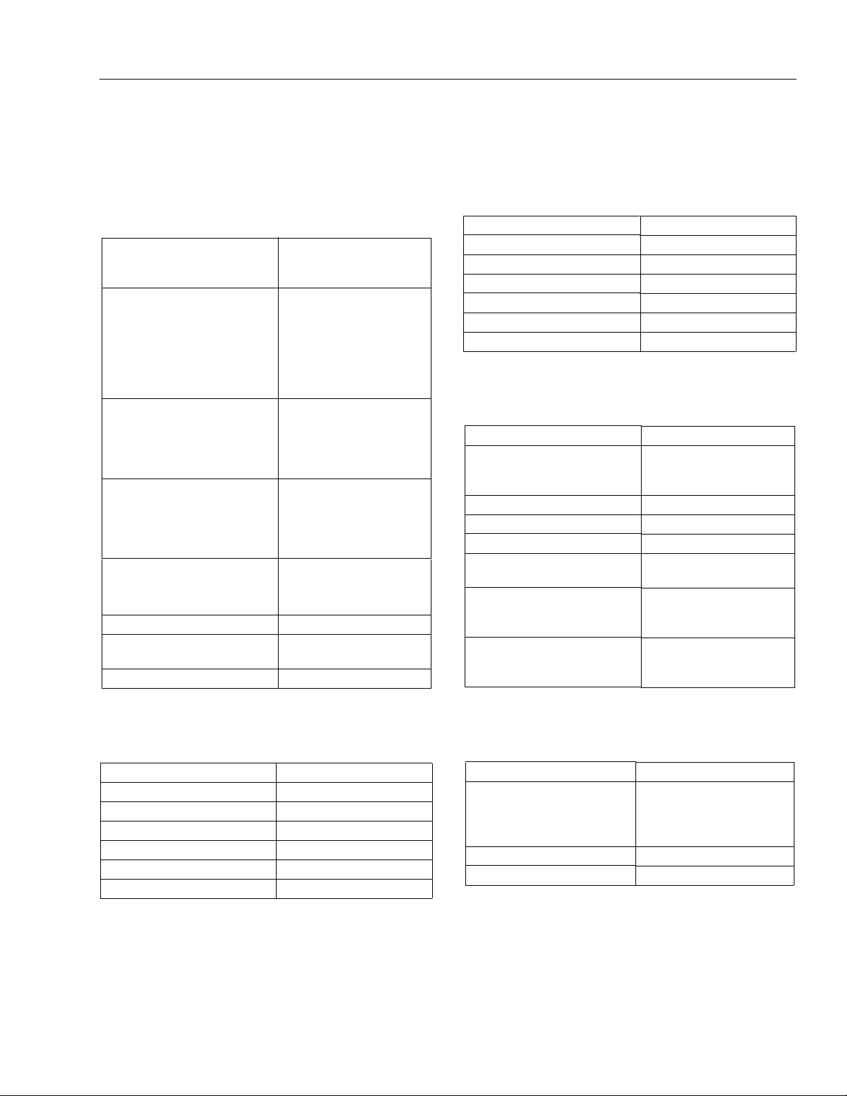
SECTION 1. SPECIFICATIONS
SECTION 1 - SPECIFICATIONS
1.1 OPERATING SPECIFICATIONS AND
PERFORMANCE DATA
Table 1-1. Operating Specifications
Unrestricted Rated Capacity
ANSI
C E & A us t ra l ia
Maximum Travel Grade (Grade-
ability)
with Boom retracted and approximately horizontal. Tower Boom
fully lowered (if equipped).
2 WD
4 WD
Maximum Travel Grade (Sideslope) with Boom retracted and
approximately horizontal. Tower
Boom fully lowered (if equipped)
- ANSI Markets.
Maximum Travel Grade (Sides-
lope) with Boom retracted and
approximately horizontal. Tower
Boom fully lowered (if equipped)
- CE & Australia Markets.
Ground Bearing Pressure
Pn e u ma ti c
Fo a m F il l e d
Maximum Drive Speed: 4.5 mph (2.0 m/s)
Maximum Hyd. Operating Pres-
sure
Electrical System Voltage 12 volts
500 lb. (227 kg)
500 lb. (230 kg)
65 psi (4.57 kg/cm2)
65 psi (4.57 kg/cm2)
4500 psi (310 Bar)
30%
45%
5°
4°
1.2 DIMENSIONAL DATA
Table 1-3. Dimensional Data
Overall Width 7 ft. 8.25 in. (2.34 m)
Tailswing 0
Stowed Height 7 ft. 6 in. (2.29 m)
Stowed Length-450A SII 21 ft. 11 in. (6.68 m)
Stowed Length-450AJ SII 22 ft. 0.25 in. (6.71 m)
Wheel base 7 ft. 8 in. (2.34 m)
Ground Clearance 11.5 in. (0.29 m)
1.3 CHASSIS
Table 1-4. Chassis Specifications
Swing 360° non-continuous
Rated Gradeability
2 WD
4 WD
Max. Tire Load 7200 lb. (3266 kg)
Axle Oscillation 8 in. (0.2 m)
System Voltage 12 Volts
Max. Hydraulic System Operating
Pressure
Gross Machine Weight - 450A SII
Pn e um a ti c Ti r es
Fo a m- Fi l l ed Ti r es
Gross Machine Weight - 450AJ SII
Pn e um a ti c Ti r es
Fo a m- Fi l l ed Ti r es
12,750 lbs. (5783 kg)
13,000 lbs. (5897 kg)
13,250 lbs. (6010 kg)
13,550 lbs. (6146 kg)
30%
45%
4500 psi
(310 bar)
1.1 REACH SPECIFICATIONS
Table 1-2. Reach Specifications
Max. Platform Height 45ft. (13.72 M)
Max. Horizontal Reach-450A SII 24 ft. 7.25 in. (7.50 M)
Max. Horizontal Reach-450AJ SII 24 ft. 6 in. (7.47 M)
Up & Over Height-450A SII 25 ft. 9.5 in. (7.56 M)
Up & Over Height-450AJ SII 25 ft. 10 in. (7.57 M)
M ai n Bo o m U p An g le 75°
M ai n Bo o m D o wn A ng l e -24°
1.4 CAPACITIES
Table 1-5. Capacities
Fuel Tank 17 gallons (64.3 liters)
Hydraulic Tank 27 gallons (102 liters)
23.6 gal. (89 liters) to the mid
point of upper sight window
(cold)
Drive Hub 23.75 oz. (0.7 liters)
Drive Brake 2.7 oz. (0.08 liters)
3121290 – JLG Lift – 1-1
Page 18
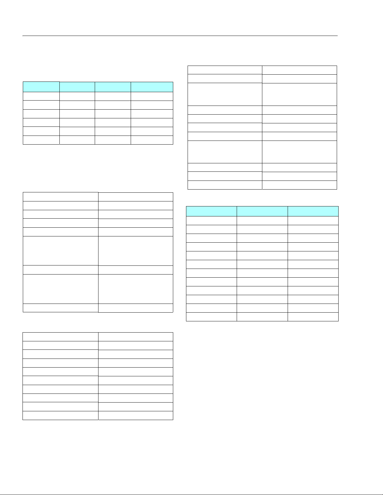
SECTION 1 - SPECIFICATIONS
1.5 TIRES
Table 1-6. Tires
Size Typ e Pressure Weight
12x16.5 Pneumatic 90 psi (6 Bar) 128 lb (58 kg)
12x16.5 Foam-Filled N/A 328 lb (149 kg)
33/1550x16.5 Pneumatic 90 psi ( 6 Bar) 135 lb (61 kg)
33/1550x16.5 Foam-Filled N/A 395 lb (179 kg)
14x17.5 Pneumatic 90psi (6 Bar) 170 lb (77.2 kg)
14x17.5 Foam-Filled N/A 440 lb (200 kg)
1.6 ENGINE
NOTE: RPM Tolerances are ± 100.
Fuel Diesel
No. of Cylinders 3
Bore 3.7 in. (94 mm)
Stroke 4.4 in. (112 mm)
Displacement 142 cu. in. (2331 cm³)
Oil Capacity
c ra n kc a se
c oo l er
t ot a l c a pa c it y
Low RPM 1200
Mid RPM
Tower Lift, Upper Lift, Tele
S wi n g, Ba s ke t Le v el , Ba s ke t
R ot a te , J i b Li f t
High RPM 2800
Table 1-7. Deutz D2011L03
6.3 Qt (6 L)
4 .7 5 Qt ( 4. 5 L)
11 Qt (10.5 L)
1800
1500
Table 1-8. Deutz 2.9 L4
Table 1-9. GM 3.0L
Fuel Gasoline or Gasoline/LP Gas
No. of Cylinders 4
BHP
G as o li n e
L P
83 hp @ 3000 rpm
75 hp @ 3000 rpm
Bore 4.0 in. (101.6 mm)
Stroke 3.6 in. (91.44 mm)
Displacement 181 cu.in. (3.0 L, 2966 cc)
Oil Capacity w/filter 4.5 qts. (4.25 L)
Minimum Oil Pressure
a t i d le
H ot
6 psi (0.4 Bar) @ 1000 rpm
18 psi (1.2 Bar) @ 2000 rpm
Compression Ratio 9.2:1
Firi ng Orde r 1-3-4-2
Max. RPM 2800
Table 1-10. Component Weights - 450
Component Pounds Kilograms
Frame (Bare) 1531 695
Turntable (Bare) 1355 615
Boom Link 180 82
Boom Timing Link 30 14
Upper Upright 217 98
Lower Upright 115 52
Lower Bo om 497 225
Mid Boom 385 175
Upper Boom 1065 484
4 Wheel Drive Axle 266 121
2 Wheel Drive Axle 258 117
Counterweight 2297 1042
Fuel Diesel
No. of Cylinders 4
BHP 48.8 hp (36.4 kW)
Bore 3.6 in. (92 mm)
Stroke 4.3 in. (110 mm)
Displacement 177 cu. in. (2.9L)
Oil Capacity w/filter 9.4 Qt (8.9 L)
Compression Ratio 18.4:1
Firi ng Ord er 1-3-4-2
Max. RPM 2600
1-2 – JLG Lift – 3121290
Page 19
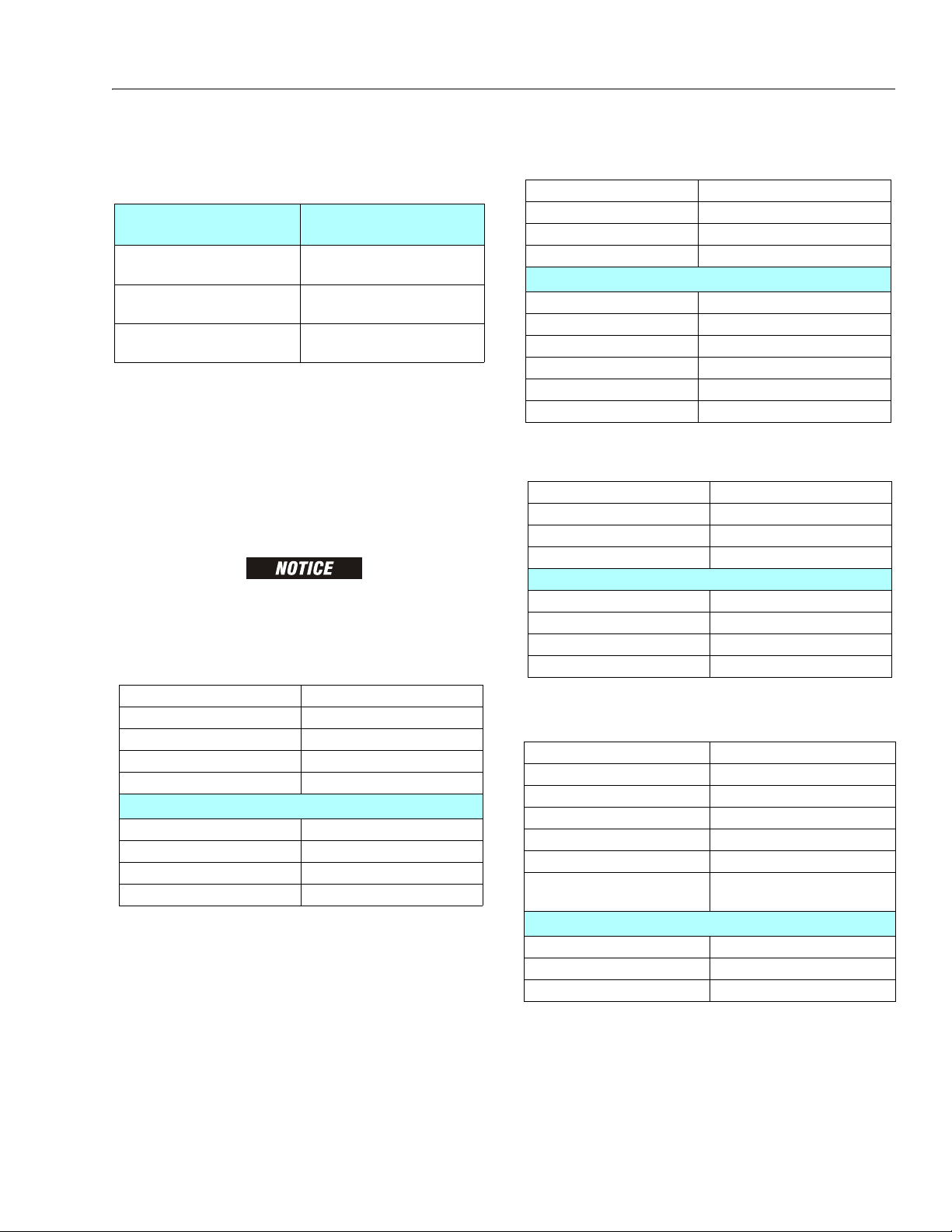
1.8 HYDRAULIC OIL
Table 1-12. Mobilfluid 424 Specs
SAE Grade 10W30
Gravity, API 29.0
Density, Lb/Gal. 60°F 7.35
Pour Point, Max -46°F (-43°C)
Flash Point, Min. 442°F (228°C)
Viscosity
Brookfield, cP at -18°C 2700
at 40° C 55 cSt
at 100° C 9.3 cSt
Viscos ity Ind ex 152
Table 1-13. Mobil DTE 13M Specs
ISO Viscosity Grade #32
Specific Gravity 0.877
Pour Point, Max -40°F (-40°C )
Flash Point, Min. 330°F (166°C)
Viscosity
at 40° C 33cSt
at 100° C 6.6 cSt
at 100° F 169 SUS
at 210° F 48 SUS
cp at -20° F 6,200
Viscos ity Inde x 14 0
Table 1-14. UCon Hydrolube HP-5046
Type Synthetic Biodegradable
Specific Gravity 1.082
Pour Point, M ax -58° F (-50 °C)
pH 9.1
Viscosity
at 0° C (32° F) 340 cSt (1600SUS)
at 40° C (104° F) 46 cSt (215SUS)
at 65° C (150° F) 22 cSt (106SUS)
Viscosity Index 170
Table 1-15. Mobil EAL H 46 Specs
Type Synthetic Biodegradable
ISO Viscosity Grade 46
Specific Gravity .910
Pour Po int -44° F (-42 °C)
Flash Point 500°F (260°C)
Operating Temp. 0 to 180°F (-17 to 162°C)
Weight 7.64 lb. per gal.
(0.9 kg per liter)
Viscosity
at 40° C 45 cSt
at 100° C 8.0 cSt
Viscosity Index 153
Table 1-11. Hydraulic Oil
SECTION 1 - SPECIFICATIONS
Hydraulic System Operating
Temperature Range
+0° to + 180° F
(-18° to +83° C)
+0° to + 210° F
(-18° to +99° C)
+50° to + 210° F
(+10° to +99° C
NOTE: Hydraulic oils must have anti-wear qualities at least to API
Service Classification GL-3, and sufficient chemical stability for mobile hydraulic system service. JLG Industries recommends Mobilfluid 424 hydraulic oil with an SAE
viscosity index of 152.
NOTE: When temperatures remain consistently below 20 degrees
F. (-7 degrees C.), JLG Industries recommends using Mobil
DTE13.
ASIDE FROM JLG RECOMMENDATIONS, IT IS NOT ADVISABLE TO MIX OILS OF DIFFERENT BRANDS OR TYPES. THEY MAY NOT CONTAIN REQUIRED ADDITIVES OR BE
OF COMPARABLE VISCOSITIES. IF USE OF HYDRAULIC OIL OTHER THAN MOBILFLUID
424 IS DESIRED, CONTACT JLG INDUSTRIES FOR PROPER RECOMMENDATIONS.
S.A.E. Viscosity
Grade
10W
10W-20, 10W30
20W-20
3121290 – JLG Lift – 1-3
Page 20
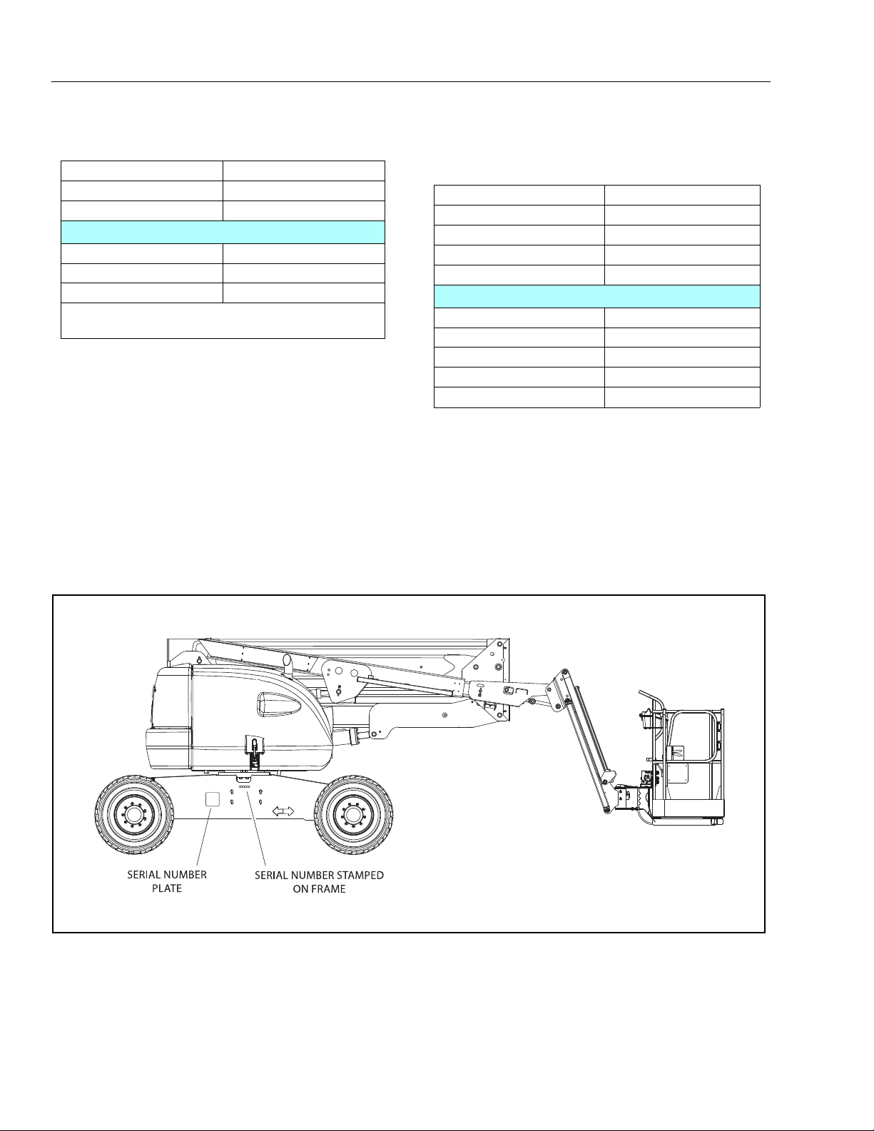
SECTION 1 - SPECIFICATIONS
Table 1-16. Exxon Univis HVI 26 Specs
Specific Gravity 32.1
Pour Point -76°F (-60°C)
Flash Point 217°F (103°C)
Viscosity
at 40° C 25.8 cSt
at 100° C 9.3 cSt
Viscosity Index 376
NOTE: Mobil/Exxon recommends checking oil viscosity
annually.
Table 1-17. Quintolubric 888-46
Density 0.91 @ 15°C (59°F)
Pour Po int <-2 0°C (< -4°F)
Flash Point 275°C (527°F)
Fire Point 325°C (617°F)
Autoignition Temperature 450°C (842°F)
Viscosity
at 0° C (32°F) 360 cSt
at 20° C (68°F) 102 cSt
at 40° C (104°F) 46 cSt
at 100° C (212°F) 10 cSt
Viscosity Index 220
1.9 SERIAL NUMBER LOCATION
A serial number plate is affixed to left rear side of frame. If
serial number plate is damaged or missing, machine serial
number is stamped on left side of frame.
1-4 – JLG Lift – 3121290
Figure 1-1. Serial Number Locations
Page 21
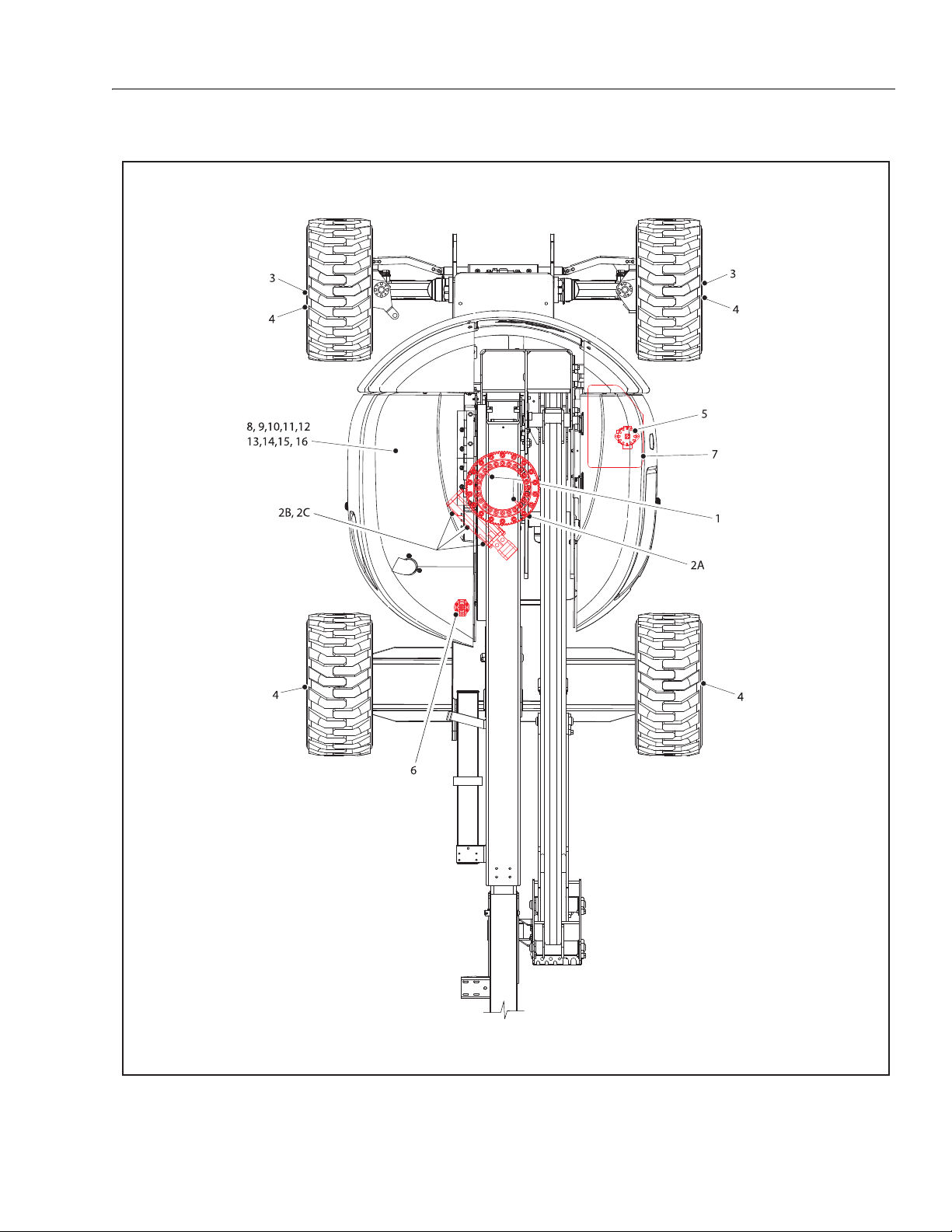
SECTION 1 - SPECIFICATIONS
Figure 1-2. Operator Maintenance and Lubrication Diagram
3121290 – JLG Lift – 1-5
Page 22
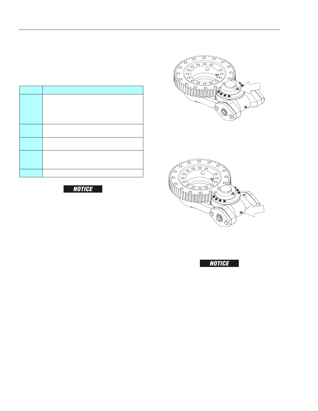
SECTION 1 - SPECIFICATIONS
1.10 OPERATOR MAINTENANCE
NOTE: The following numbers correspond to those in Figure 1-2.,
Operator Maintenance and Lubrication Diagram.
Table 1-18. Lubrication Specifications
KEY SPECIFICATIONS
Multipurpose Grease having a minimum dripping
point of 350° F (177° C). Excellent water resistance
MPG
EPGL
HO
EO
OGL
LUBRICATION INTERVALS ARE BASED ON MACHINE OPERATION UNDER NORMAL CONDITIONS. FOR MACHINES USED IN MULTI-SHIFT OPERATIONS AND/
OR EXPOSED TO HOSTILE ENVIRONMENTS OR CONDITIONS, LUBRICATION
FREQUENCIES MUST BE INCREASED ACCORDINGLY.
and adhesive qualities, and being of extreme pressure type.
(Timken OK 40 pounds minimum.)
Extreme Pressure Gear Lube (oil) meeting API service classification GL-5 or MIL-Spec MIL-L-2105
Hydraulic Oil. API service classification GL-3, e.g.
Mobilfluid 424.
Engine (crankcase) Oil. Gas - API SF, SH, SG class, MILL-2104. Diesel - API CC/CD class, MIL-L-2104B/MIL-L2104C.
Open Gear Lubricant - Mobiltac 375 or equivalent.
2. Swing Bearing/Worm Gear Teeth
Lube Point(s) - Grease Fitting
Capacity - A/R
Lube - Lubriplate 930-AAA
Interval - A/R
NOTE: It is recommended as good practice to replace all filters at
the same time.
1. Swing Bearing - Internal Ball Bearing
Lube Point(s) - 2 Grease Fittings
Capacity - A/R
Lube - Mobil SHC 460
Interval - Every 3 months or 150 hrs of operation
Lube Point(s) - Grease Fitting (See Note)
Capacity - A/R
Lube - Mobil SHC 007
Interval - A/R
OVERGREASING BEARINGS WILL RESULT IN DAMAGE TO OUTER SEAL IN
HOUSING. DO NOT OVERGREASE BEARINGS.
NOTE: If necessary, install grease fitting into worm gear housing
and grease. Replace fitting with pipe plug when complete.
1-6 – JLG Lift – 3121290
Page 23
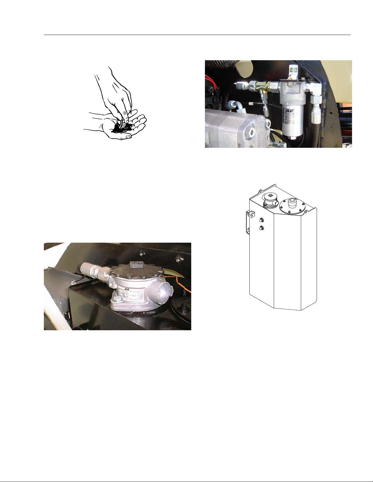
SECTION 1 - SPECIFICATIONS
3. Wheel Bearings (2WD Only)
Lube Point(s) - Repack
Capacity - A/R
Lube - MPG
Interval - Every 2 years or 1200 hours of operation
4. Wheel Drive Hub
Lube Point(s) - Level/Fill Plug
Capacity - 17 oz. (0.5 L) - 1/2 Full
Lube - EPGL
Interval - Check level every 3 months or 150 hrs of
operation; change every 2 years or 1200 hours of
operation
5. Hydraulic Return Filter
6. Hydraulic Charge Filter
Interval - Change after first 50 hrs. and every 6 months
or 300 hrs. thereafter, or as shown by Condition Indi
cator.
7. Hydraulic Tank
-
Lube Point(s) - Fill Cap
Capacity - 27 gallons (102 liters); 23.6 gal. (89 liters) to
Interval - Change after first 50 hrs. and every 6 months
or 300 hrs. thereafter or as indicated by Condition
Indicator.
mid point of upper sight window (cold) Lube - HO
Interval - Check Level daily; Change every 2 years or
1200 hours of operation.
3121290 – JLG Lift – 1-7
Page 24

SECTION 1 - SPECIFICATIONS
8. Oil Change w/Filter - Deutz D2011 L03
Fill Cap/Spin-on Element (JLG P/N7016641)
Capacity - 11 Qt (10.5 L) Crankcase; 5 Qt (4.7 L)
Cooler
Lube - EO
Interval - Every Year or 1200 hours of operation
Comments - Check level daily/Change in accordance
with engine manual. Refer to Figure 1-3, Deutz Engine
Dipstick Markings.
9. Oil Change w/Filter - Deutz 2.9 L4
Lube Point(s) - Fill Cap/Spin-on Element
Capacity - 10 Qt (9.4 L)
Lube - EO
Interval - Every Year or 600 hours of operation
Comments - Check level daily/Change in accordance
with engine manual.
10. Oil Change w/Filter - GM
Lube Point(s) - Fill Cap/Spin-on Element
Capacity - 4.5 qt. (4.25 L) w/filter
Lube - EO
Interval - 3 Months or 150 hours of operation
Comments - Check level daily/Change in accordance
with engine manual.
11. Fuel Filter - Deutz
Figure 1-3. Deutz Engine Dipstick Markings
Lube Point(s) - Replaceable Element
Interval - Every Year or 600 hours of operation
1-8 – JLG Lift – 3121290
Page 25
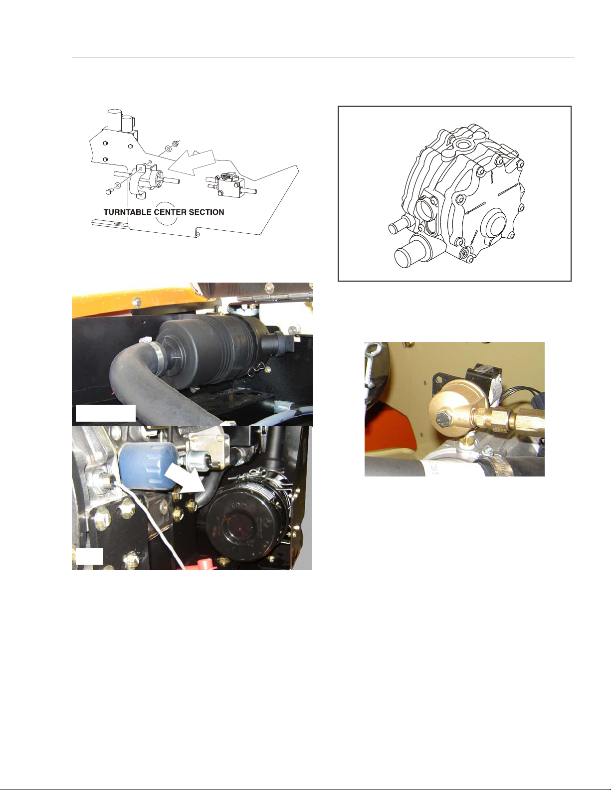
SECTION 1 - SPECIFICATIONS
DEUTZ, GM
CAT
12. Fuel Filter - GM
Lube Point(s) - Replaceable Element
Interval - Every 6 months or 300 hours of operation
13. Air Filter
14. 2-Stage Vaporizer (LP only)
Interval - 3 Months or 150 hours of operation
Comments - Drain oil build up. Refer to Propane Fuel
Filter Replacement in Section 3.
15. Fuel Filter (Propane) - GM Engine
Interval - 3 Months or 150 hours of operation
Comments - Replace filter. Refer to Propane Fuel Filter
Replacement in Section 3.
Lube Point(s) - Replaceable Element
Interval - Every 6 months or 300 hours of operation or
as indicated by the condition indicator
3121290 – JLG Lift – 1-9
Page 26
SECTION 1 - SPECIFICATIONS
REFERENCE JLG ANAEROBIC THREAD LOCKING COMPOUND
JLG P/N Loctite® P/N ND Industries P/N
Description
0100011
242
TM
Vibra-TITE
TM
121
Medium Strength (Blue)
0100019
271
TM
Vibra-TITE
TM
140
High Strength (Red)
0100071
262
TM
Vibra-TITE
TM
131
Medium - High Strength (Red)
Size TPI Bolt Dia
Tensile
Stress Area
Clamp Load
In Sq In LB IN-LB [N.m] IN-LB [N.m] IN-LB [N.m] IN-LB [N.m]
4 40 0.1120 0.00604 380 8 0.9 6 0.7
48 0.1120 0.00661 420 9 1.0 7 0.8
6 32 0.1380 0.00909 580 16 1.8 12 1.4
40 0.1380 0.01015 610 18 2.0 13 1.5
8 32 0.1640 0.01400 900 30 3.4 22 2.5
36 0.1640 0.01474 940 31 3.5 23 2.6
10 24 0.1900 0.01750 1120 43 4.8 32 3.5
32 0.1900 0.02000 1285 49 5.5 36 4
1/4 20 0.2500 0.0318 2020 96 10.8 75 9 105 12
28 0.2500 0.0364 2320 120 13.5 86 10 135 15
In Sq In LB FT-LB [N.m] FT-LB [N.m] FT-LB [N.m] FT-LB [N.m]
5/16180.31250.052433401723131819261622
24 0.3125 0.0580 3700 19 26 14 19 21 29 17 23
3/8 16 0.3750 0.0775 4940 30 41 23 31 35 48 28 38
24 0.3750 0.0878 5600 35 47 25 34 40 54 32 43
7/16140.43750.106368005068354755754561
20 0.4375 0.1187 7550 55 75 40 54 60 82 50 68
1/2 13 0.5000 0.1419 9050 75 102 55 75 85 116 68 92
20 0.5000 0.1599 10700 90 122 65 88 100 136 80 108
9/16 12 0.5625 0.1820 11600 110 149 80 108 120 163 98 133
18 0.5625 0.2030 12950 120 163 90 122 135 184 109 148
5/8 11 0.6250 0.2260 14400 150 203 110 149 165 224 135 183
18 0.6250 0.2560 16300 170 230 130 176 190 258 153 207
3/4 10 0.7500 0.3340 21300 260 353 200 271 285 388 240 325
16 0.7500 0.3730 23800 300 407 220 298 330 449 268 363
7/8 9 0.8750 0.4620 29400 430 583 320 434 475 646 386 523
14 0.8750 0.5090 32400 470 637 350 475 520 707 425 576
1 8 1.0000 0.6060 38600 640 868 480 651 675 918 579 785
12 1.0000 0.6630 42200 700 949 530 719 735 1000 633 858
1 1/8 7 1.1250 0.76 30 42300 800 1085 600 8 13 840 1142 714 968
12 1.1250 0.8560 47500 880 1193 660 895 925 1258 802 1087
1 1/4 7 1.2500 0.96 90 53800 1120 1518 840 1139 1175 1598 1009 1368
12 1.2500 1.0730 59600 1240 1681 920 1247 1300 1768 1118 1516
1 3/8 6 1.3750 1.15 50 64100 1460 1979 1100 1491 1525 2074 1322 1 792
12 1.3750 1.3150 73000 1680 2278 1260 1708 1750 2380 1506 2042
1 1/2 6 1.5000 1.40 50 78000 1940 2630 1460 1979 2025 2754 1755 2 379
12 1.5000 1.5800 87700 2200 2983 1640 2224 2300 3128 1974 2676
NO. 5000059 REV. J
Values for Zinc Yellow Chromate Fasteners (Ref 4150707)
SAE GRADE 5 BOLTS & GRADE 2 NUTS
Torque
(Dry)
Torque
Loctite® 262
TM
Vibra-TITE
TM
131
Torque
Lubricated
Torque
Loctite® 242
TM
or 271
TM
Vibra-TITE
TM
111 or 140
3. * ASSEMBLY USES HARDENED WASHER
NOTES: 1. THESE TORQUE VA LUES DO NOT APPLY TO CADMIUM PLATED FASTENERS
2. ALL TORQUE VALUES ARE STATIC TORQUE MEASURED PER STANDARD AUDIT METHODS TOLERANCE = ±10%
Figure 1-4. Torque Chart (SAE Fasteners - Sheet 1 of 7)
1-10 – JLG Lift – 3121290
Page 27
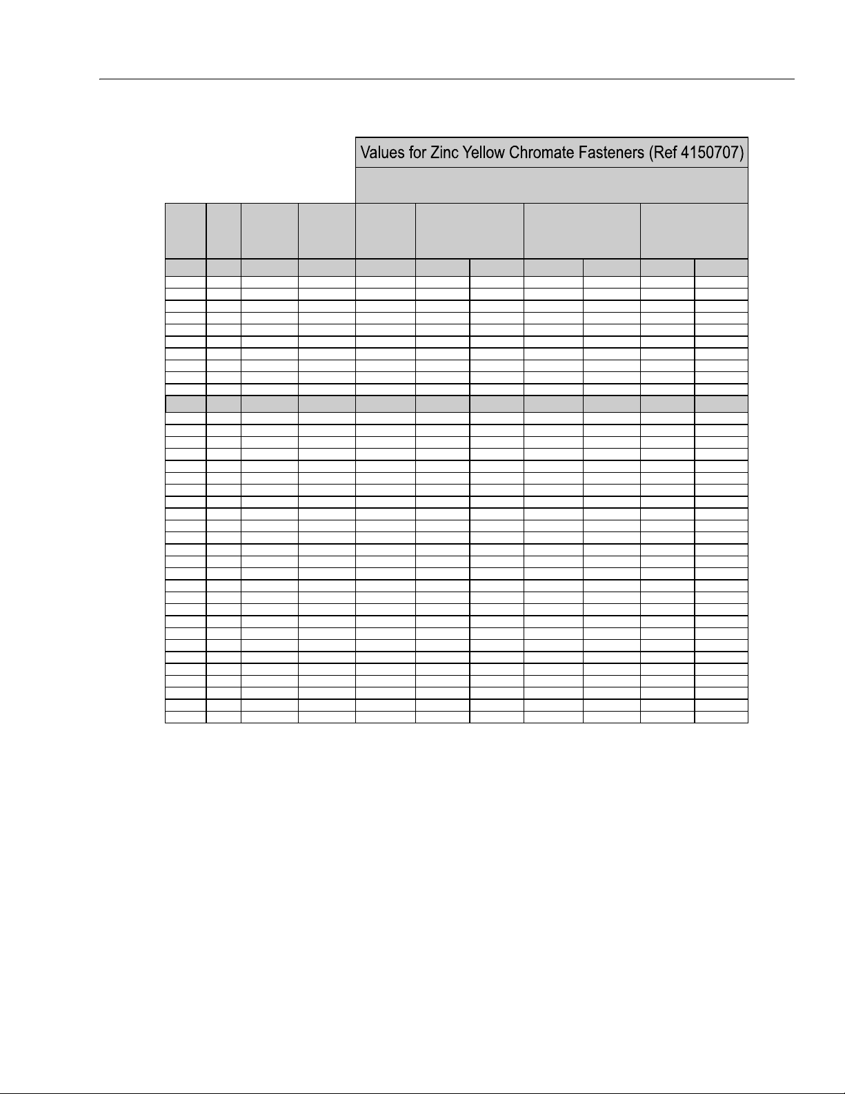
SECTION 1 - SPECIFICATIONS
Size TPI Bolt Dia
Tensile
Stress Area
Clamp Load
In Sq In
4 40 0.1120 0.00604
48 0.1120 0.00661
6 32 0.1380 0.00909
40 0.1380 0.01015
8 32 0.1640 0.01400
36 0.1640 0.01474
10 24 0.1900 0.01750
32 0.1900 0.02000
1/4 20 0.2500 0.0318
28 0.2500 0.0364
In Sq In
5/16 18 0.3125 0.0524
24 0.3125 0.0580
3/8 16 0.3750 0.0775
24 0.3750 0.0878
7/16 14 0.4375 0.1063
20 0.4375 0.1187
1/2 13 0.5000 0.1419
20 0.5000 0.1599
9/16 12 0.5625 0.1820
18 0.5625 0.2030
5/8 11 0.6250 0.2260
18 0.6250 0.2560
3/4 10 0.7500 0.3340
16 0.7500 0.3730
7/8 9 0.8750 0.4620
14 0.8750 0.5090
1 8 1.0000 0.6060
12 1.0000 0.6630
1 1/8 7 1.1250 0.7630
12 1.1250 0.8560
1 1/4 7 1.2500 0.9690
12 1.2500 1.0730
1 3/8 6 1.3750 1.1550
12 1.3750 1.3150
1 1/2 6 1.5000 1.4050
12 1.5000 1.5800
NO. 5000059 REV. J
3. * ASSEMBLY USES HARDENED WASHER
NOTES: 1. THESE TORQUE VALUES DO NOT APPLY TO CADMIUM PLATED FASTENERS
2. ALL TORQUE VALUES ARE STATIC TORQUE MEASURED PER STANDARD AUDIT METHODS TOLERANCE = ±10%
LB IN-LB [N.m] IN-LB [N.m] IN-LB [N.m]
1320 43 5
1580 60 7
1800 68 8
2860 143 16 129 15
3280 164 19 148 17
LB FT-LB [N.m] FT-LB [N.m] FT-LB [N.m
4720 25 35 20 25 20 25
5220 25 35 25 35 20 25
7000456040 553550
7900 50 70 45 60 35 50
9550 70 95 65 90 50 70
10700 80 110 70 95 60 80
12750 105 145 95 130 80 110
14400 120 165 110 150 90 120
16400 155 210 140 190 115 155
18250 170 230 155 210 130 175
20350 210 285 190 260 160 220
23000 240 325 215 290 180 245
30100 375 510 340 460 280 380
33600 420 570 380 515 315 430
41600 605 825 545 740 455 620
45800 670 910 600 815 500 680
51500 860 1170 770 1045 645 875
59700 995 1355 895 1215 745 1015
68700 1290 1755 1160 1580 965 1310
77000 1445 1965 1300 1770 1085 1475
87200 1815 2470 1635 2225 1365 1855
96600 2015 2740 1810 2460 1510 2055
104000 2385 3245 2145 2915 1785 2430
118100 2705 3680 2435 3310 2030 2760
126500 3165 4305 2845 3870 2370 3225
142200 3555 4835 3200 4350 2665 3625
Torque
(Loctite® 242
TM
or 271
TM
OR Vibra-TITE
TM
111 or
140) K=.18
Torque
(Loctite® 262
TM
or Vibra-
TITE
TM
131)
K=0.15
SAE GRADE 8 (HEX HD) BOLTS & GRADE 8 NUTS*
Torque
(Dry or Loctite® 263)
K= 0.20
3121290 – JLG Lift – 1-11
Figure 1-5. Torque Chart (SAE Fasteners - Sheet 2 of 7)
Page 28
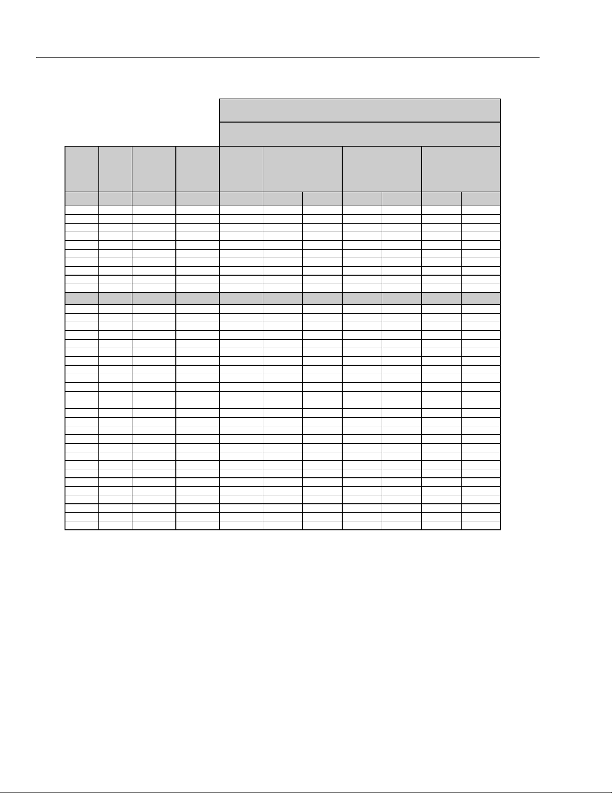
SECTION 1 - SPECIFICATIONS
Size TPI Bolt Dia
Tensile
Stress Area
Clamp Load
See Note 4
In Sq In LB IN-LB [N.m] IN-LB [N.m] IN-LB [N.m]
4 40 0.1120 0.00604
48 0.1120 0.00661
6 32 0.1380 0.00909
40 0.1380 0.01015
8 32 0.1640 0.01400
36 0.1640 0.01474
10 24 0.1900 0.01750
32 0.1900 0.02000
1/4 20 0.2500 0.0318 2860 122 14 114 13
28 0.2500 0.0364 3280 139 16 131 15
In Sq In LB FT-LB [N.m] FT-LB [N.m] FT-LB [N.m]
5/16 18 0.3125 0.0524 4720 20 25 20 25 20 25
24 0.3125 0.0580 5220 25 35 20 25 20 25
3/8 16 0.3750 0.0775 7000 35 50 35 50 35 50
24 0.3750 0.0878 7900 40 55 40 55 35 50
7/16 14 0.4375 0.1063 9550 60 80 55 75 50 70
20 0.4375 0.1187 10700 65 90 60 80 60 80
1/2 13 0.5000 0.1419 12750 90 120 85 115 80 110
20 0.5000 0.1599 14400 100 135 95 130 90 120
9/16 12 0.5625 0.1820 16400 130 175 125 170 115 155
18 0.5625 0.2030 18250 145 195 135 185 130 175
5/8 11 0.6250 0.2260 20350 180 245 170 230 160 220
18 0.6250 0.2560 23000 205 280 190 260 180 245
3/4 10 0.7500 0.3340 30100 320 435 300 410 280 380
16 0.7500 0.3730 33600 355 485 335 455 315 430
7/8 9 0.8750 0.4620 41600 515 700 485 660 455 620
14 0.8750 0.5090 45800 570 775 535 730 500 680
1 8 1.0000 0.6060 51500 730 995 685 930 645 875
12 1.0000 0.6630 59700 845 1150 795 1080 745 1015
1 1/8 7 1.1250 0.7630 68700 1095 1490 1030 1400 965 1310
12 1.1250 0.8560 77000 1225 1665 1155 1570 1085 1475
1 1/4 7 1.2500 0.9690 87200 1545 2100 1455 1980 1365 1855
12 1.2500 1.0730 96600 1710 2325 1610 2190 1510 2055
1 3/8 6 1.3750 1.1550 104000 2025 2755 1905 2590 1785 2430
12 1.3750 1.3150 118100 2300 3130 2165 2945 2030 2760
1 1/2 6 1.5000 1.4050 126500 2690 3660 2530 3440 2370 3225
12 1.5000 1.5800 142200 3020 4105 2845 3870 2665 3625
NO. 5000059 REV. J
4. CLAMP LOAD LISTED FOR SHCS IS SAME AS GRADE 8 OR CLASS 10.9 AND DOES NOT REPRESENT FULL STRENGTH
CAPABILITY OF SHCS. IF HIGHER LOAD IS REQUIRED, ADDITIONAL TESTING IS REQUIRED.
SOCKET HEAD CAP SCREWS
Magni Coating (Ref 4150701)*
Torque
(Dry) K = .17
Torque
(Loctite® 242
TM
or 271
TM
OR Vibra-TITE
TM
111 or
140 OR Precoat 85®
K=0.16
Torque
(Loctite® 262
TM
or Vibra-
TITE
TM
131)
K=0.15
2. ALL TORQUE VALUES ARE STATIC TORQUE MEASURED PER STANDARD AUDIT METHODS TOLERANCE = ±10%
NOTES: 1. THESE TORQUE VALUES DO NOT APPLY TO CADMIUM PLATED FASTENERS
*3. ASSEMBLY USES HARDENED WASHER OR FASTENER IS PLACED AGAINST PLATED STEEL OR RAW ALUMINUM
1-12 – JLG Lift – 3121290
Figure 1-6. Torque Chart (SAE Fasteners - Sheet 3 of 7)
Page 29

Size TPI Bolt Dia
Tensile
Stress Area
Clamp Load
See Note 4
In Sq In LB IN-LB [N.m] IN-LB [N.m] IN-LB [N.m]
4 40 0.1120 0.00604
48 0.1120 0.00661
6 32 0.1380 0.00909
40 0.1380 0.01015
8 32 0.1640 0.01400
36 0.1640 0.01474
10 24 0.1900 0.01750
32 0.1900 0.02000
1/4 20 0.2500 0.0318 2860 143 16 129 15
28 0.2500 0.0364 3280 164 19 148 17
In Sq In LB FT-LB [N.m] FT-LB [N.m] FT-LB [N.m]
5/16 18 0.3125 0.0524 4720 25 35 20 25 20 25
24 0.3125 0.0580 5220 25 35 25 35 20 25
3/8 16 0.3750 0.0775 7000 45 60 40 55 35 50
24 0.3750 0.0878 7900 50 70 45 60 35 50
7/16 14 0.4375 0.1063 9550 70 95 65 90 50 70
20 0.4375 0.1187 10700 80 110 70 95 60 80
1/2 13 0.5000 0.1419 12750 105 145 95 130 80 110
20 0.5000 0.1599 14400 120 165 110 150 90 120
9/16 12 0.5625 0.1820 16400 155 210 140 190 115 155
18 0.5625 0.2030 18250 170 230 155 210 130 175
5/8 11 0.6250 0.2260 20350 210 285 190 260 160 220
18 0.6250 0.2560 23000 240 325 215 290 180 245
3/4 10 0.7500 0.3340 30100 375 510 340 460 280 380
16 0.7500 0.3730 33600 420 570 380 515 315 430
7/8 9 0.8750 0.4620 41600 605 825 545 740 455 620
14 0.8750 0.5090 45800 670 910 600 815 500 680
1 8 1.0000 0.6060 51500 860 1170 775 1055 645 875
12 1.0000 0.6630 59700 995 1355 895 1215 745 1015
1 1/8 7 1.1250 0.7630 68700 1290 1755 1160 1580 965 1310
12 1.1250 0.8560 77000 1445 1965 1300 1770 1085 1475
1 1/4 7 1.2500 0.9690 87200 1815 2470 1635 2225 1365 1855
12 1.2500 1.0730 96600 2015 2740 1810 2460 1510 2055
1 3/8 6 1.3750 1.1550 104000 2385 3245 2145 2915 1785 2430
12 1.3750 1.3150 118100 2705 3680 2435 3310 2030 2760
1 1/2 6 1.5000 1.4050 126500 3165 4305 2845 3870 2370 3225
12 1.5000 1.5800 142200 3555 4835 3200 4350 2665 3625
NO. 5000059 REV. J
4. CLAMP LOAD LISTED FOR SHCS IS SAME AS GRADE 8 OR CLASS 10.9 AND DOES NOT REPRESENT FULL STRENGTH
CAPABILITY OF SHCS. IF HIGHER LOAD IS REQUIRED, ADDITIONAL TESTING IS REQUIRED.
SOCKET HEAD CAP SCREWS
Torque
(Dry)
K = .20
Torque
(Loctite® 242TM or 271
TM
OR Vibra-TITE
TM
111 or
140 OR Precoat 85®
K=0.18
Zinc Yellow Chromate Fasteners (Ref 4150707)*
2. ALL TORQUE VALUES ARE STATIC TORQUE MEASURED PER STANDARD AUDIT METHODS TOLERANCE = ±10%
NOTES: 1. THESE TORQUE VALUES DO NOT APPLY TO CADMIUM PLATED FASTENERS
*3. ASSEMBLY USES HARDENED WASHER OR FASTENER IS PLACED AGAINST PLATED STEEL OR RAW ALUMINUM
Torque
(Loctite® 262
TM
or Vibra-
TITE
TM
131)
K=0.15
SECTION 1 - SPECIFICATIONS
3121290 – JLG Lift – 1-13
Figure 1-7. Torque Chart (SAE Fasteners - Sheet 4 of 7)
Page 30
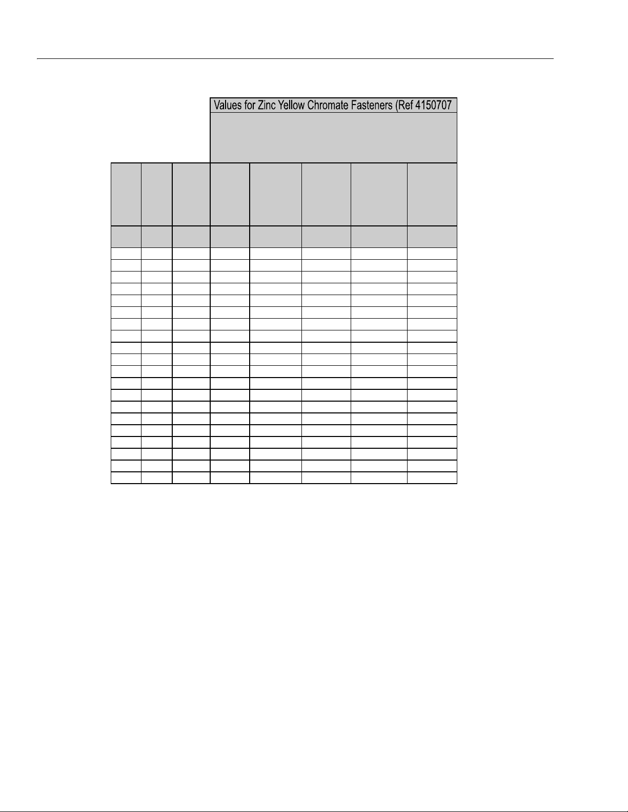
SECTION 1 - SPECIFICATIONS
Size PITCH
Tensile
Stress
Area
Clamp
Load
Torque
(Dry or Loctite®
263
TM
)
Torque
(Lub)
Torque
(Loctite® 262
TM
OR Vibra-
TITE
TM
131)
Torque
(Loctite®
242
TM
or 271
TM
OR Vibra-
TITE
TM
111 or
140)
Sq mm K N [N.m ] [N.m] [N.m] [N. m]
3 0.5 5.03 2.19 1.3 1.0 1.2 1.4
3.5 0.6 6.78 2.95 2.1 1.6 1.9 2.3
4 0.7 8.78 3.82 3.1 2.3 2.8 3.4
5 0.8 14.20 6.18 6.2 4.6 5.6 6.8
6 1 20.10 8.74 11 7.9 9.4 12
7 1 28.90 12.6 18 13 16 19
8 1.25 36.60 15.9 26 19 23 28
10 1.5 58.00 25.2 50 38 45 55
12 1.75 84.30 36.7 88 66 79 97
14 2 115 50.0 140 105 126 154
16 2 157 68.3
219 164 197 241
18 2.5 192 83.5 301 226 271 331
20 2.5 245 106.5 426 320 383 469
22 2.5 303 132.0 581 436 523 639
24 3 353 153.5 737 553 663 811
27 3 459 199.5 1080 810 970 1130
30 3.5 561 244.0 1460 1100 1320 1530
33 3.5 694 302.0 1990 1490 1790 2090
36 4 817 355.5 2560 1920 2300 2690
42 4.5 1120 487.0 4090 3070 3680 4290
4. CLAMP LOAD LISTED FOR SHCS IS SAME AS GRADE 8 OR CLASS 10.9 AND DOES NOT
REPRESENT FULL STRENGTH CAPABILITY OF SHCS. IF HIGHER LOAD IS REQUIRED,
ADDITIONAL TESTING IS REQUIRED.
*3. ASSEMBLY USES HARDENED WASHER OR FASTENER IS PLACED AGAINST PLATED
STEEL OR RAW ALUMINUM
CLASS 8.8 METRIC BOLTS
CLASS 8 METRIC NUTS
NOTES: 1. THESE TORQUE VALUES DO NOT APPLY TO CADMIUM PLATED FASTENERS
2. ALL TORQUE VALUES ARE STATIC TORQUE MEASURED PER STANDARD AUDIT
METHODS TOLERANCE = ±10%
NO. 5000059 REV. J
Figure 1-8. Torque Chart (METRIC Fasteners - Sheet 5 of 7)
1-14 – JLG Lift – 3121290
Page 31

SECTION 1 - SPECIFICATIONS
Size PITCH
Tensile
Stress
Area
Clamp
Load
Torque
(Dry or Loctite®
263
TM
)
K = 0.20
Torque
(Lub OR Loctite®
242
TM
or 271TM OR
Vibra-TITE
TM
111 or
140)
K= 0.18
Torque
(Loctite® 262
TM
OR
Vibra-TITE
TM
131)
K=0.15
Sq mm KN [N.m] [N.m] [N.m]
3 0.5 5.03 3.13
3.5 0.6 6.78 4.22
4 0.7 8.78 5.47
5 0.8 14.20 8.85
6 1 20.10 12.5
7 1 28.90 18.0 25.2 22.7 18.9
8 1.25 36.60 22.8 36.5 32.8 27.4
10 1.5 58.00 36.1 70 65 55
12 1.75 84.30 52.5 125 115 95
14 2 115 71.6 200 180 150
16 2 157 97.8
315 280 235
18 2.5 192 119.5 430 385 325
20 2.5 245 152.5 610 550 460
22 2.5 303 189.0 830 750 625
24 3 353 222.0 1065 960 800
27 3 459 286.0 1545 1390 1160
30 3.5 561 349.5 2095 1885 1575
33 3.5 694 432.5 2855 2570 2140
36 4 817 509.0 3665 3300 2750
42 4.5 1120 698.0 5865 5275 4395
CLASS 10.9 METRIC BOLTS
CLASS 10 METRIC NUTS
CLASS 12.9 SOCKET HEAD CAP SCREWS M3 - M5*
4. CLAMP LOAD LISTED FOR SHCS IS SAME AS GRADE 8 OR CLASS 10.9 AND DOES NOT
REPRESENT FULL STRENGTH CAPABILITY OF SHCS. IF HIGHER LOAD IS REQUIRED,
ADDITIONAL TESTING IS REQUIRED.
*3. ASSEMBLY USES HARDENED WASHER OR FASTENER IS PLACED AGAINST PLA TED
STEEL OR RAW ALUMINUM
NOTES: 1. THESE TORQUE VALUES DO NOT APPLY TO CADMIUM PLATED FASTENERS
2. ALL TORQUE VALUES ARE STATIC TORQUE MEASURED PER STANDARD AUDIT
METHODS TOLERANCE = ±10%
NO. 5000059 REV. J
3121290 – JLG Lift – 1-15
Figure 1-9. Torque Chart (METRIC Fasteners - Sheet 6 of 7)
Page 32

SECTION 1 - SPECIFICATIONS
Size PITCH
Tensile
Stress
Area
Clamp Load
See Note 4
Torque
(Dry or Loctite®
263
TM
)
K = .17
Torque
(Lub OR Loctite®
242
TM
or 271
TM
OR Vibra-TITE
TM
111 or 140)
K = .16
Torque
(Loctite® 262
TM
OR Vibra-TITE
TM
131)
K = .15
Sq mm kN [N.m] [N.m] [N.m]
30.55.03
3.5 0.6 6.78
40.78.78
50.814.20
6120.1012.5 13 12 11
7128.9018.0 21 20 19
8 1.25 36.60 22.8 31 29 27
10 1.5 58.00 36.1 61 58 54
12 1.75 84.30 52.5 105 100 95
14 2 115 71.6 170 160 150
16 2 157
97.8 265 250 235
18 2.5 192 119.5 365 345 325
20 2.5 245 152.5 520 490 460
22 2.5 303 189.0 705 665 625
24 3 353 220.0 900 845 790
27 3 459 286.0 1315 1235 1160
30 3.5 561 349.5 1780 1680 1575
33 3.5 694 432.5 2425 2285 2140
36 4 817 509.0 3115 2930 2750
42 4.5 1120 698.0 4985 4690 4395
CLASS 12.9 SOCKET HEAD CAP SCREWS
M6 AND ABOVE*
4. CLAMP LOAD LISTED FOR SHCS IS SAME AS GRADE 8 OR CLASS 10.9 AND DOES NOT
REPRESENT FULL STRENG TH CAPABILITY OF SHCS. IF HIGHER LOAD IS REQUIRED,
ADDITIONAL TESTING IS REQUIRED.
*3. ASSEMBLY USES HARDENED WASHER OR FASTENER IS PLACED AGAINST PLATED
STEEL OR RAW ALUMINUM
NOTES: 1. THESE TORQUE VALUES DO NOT APPLY TO CADMIUM PLATED FASTENERS
2. ALL TORQUE VALUES ARE STATIC TORQUE MEASURED PER STANDARD AUDIT
METHODS TOLERANCE = ±10%
NO. 5000059 REV. J
Magni Coating (Ref 4150701)*
Figure 1-10. Torque Chart (METRIC Fasteners - Sheet 7 of 7)
1-16 – JLG Lift – 3121290
Page 33

SECTION 2. GENERAL
SECTION 2 - GENERAL
2.1 MACHINE PREPARATION, INSPECTION, AND MAINTENANCE
General
This section provides information needed by personnel
responsible to place machine in operation readiness and
maintain its safe operating condition. For maximum service
life and safe operation, ensure all necessary inspections and
maintenance have been completed before placing machine
into service.
Preparation, Inspection, and Maintenance
It is important to establish and conform to a comprehensive
inspection and preventive maintenance program. The follow
ing table outlines periodic machine inspections and maintenance recommended by JLG Industries, Inc. Consult your
national, regional, or local regulations for further requirements
for aerial work platforms. Frequency of inspections and main
tenance must be increased as environment, severity and frequency of usage requires.
Pre-Start Inspection
It is the User’s or Operator’s primary responsibility to perform a
machine Pre-Start Inspection before use daily or at each
change of operator. Reference the Operator’s and Safety Manual for completion procedures for Pre-Start Inspection. Operator and Safety Manual must be read in its entirety and
understood before Pre-Start Inspection.
Pre-Delivery Inspection and Frequent Inspection
Pre-Delivery Inspection and Frequent Inspection shall be performed by a qualified JLG equipment mechanic. JLG Industries, Inc. recognizes a qualified JLG equipment mechanic as a
person who, by possession of a recognized degree, certificate,
extensive knowledge, training, or experience, has successfully
demonstrated the ability and proficiency to service, repair, and
maintain the subject JLG product model.
Reference JLG Pre-Delivery and Frequent Inspection Form and
Inspection and Preventative Maintenance Schedule for items
requiring inspection during these inspections. Reference
appropriate areas of this manual for service and maintenance
procedures.
Annual Machine Inspection
Annual Machine Inspection must be performed on an annual
basis, no later than thirteen (13) months from date of prior
Annual Machine Inspection. JLG Industries recommends this
task be performed by a Factory-Trained Service Technician. JLG
Industries, Inc. recognizes a Factory-Trained Service Technician
as a person who has successfully completed the JLG Service
Training School for the subject JLG product model. Reference
machine Service and Maintenance Manual and appropriate
JLG inspection form for this inspection.
-
-
Reference JLG Annual Machine Inspection Form and Inspection and Preventative Maintenance Schedule for items requiring inspection during performance of this inspection.
Reference appropriate areas of this manual for service and
maintenance procedures.
For the purpose of receiving safety-related bulletins, it is
important that JLG Industries, Inc. has updated ownership
information for each machine. When performing each Annual
Machine Inspection, notify JLG Industries, Inc. of current
machine ownership.
Preventative Maintenance
With specified inspections, maintenance shall be performed
by a qualified JLG equipment mechanic. JLG Industries, Inc.
recognizes a qualified JLG equipment mechanic as a person
who, by possession of a recognized degree, certificate, exten
sive knowledge, training, or experience, has successfully demonstrated the ability and proficiency to service, repair, and
maintain the subject JLG product model.
Reference Preventative Maintenance Schedule and appropriate areas of this manual for service and maintenance procedures. Frequency of service and maintenance must be
increased as environment, severity and frequency of usage
requires.
-
Pre-Delivery Inspection and Frequent Inspection procedures
are performed in the same manner, but at different times. PreDelivery Inspection shall be performed before each sale, lease,
or rental delivery. Frequent Inspection shall be accomplished
for each machine in service for 3 months or 150 hours (which
ever comes first); out of service for a period of more than 3
months; or when purchased used. Frequency of this inspec
tion must be increased as environment, severity and frequency of usage requires.
-
-
3121290 – JLG Lift – 2-1
Page 34

SECTION 2 - GENERAL
Table 2-1. Inspection and Maintenance
Type Frequency
Pre-Start Inspection Prior to use each day; or
At each Operator change.
Pre-Delivery Inspec tion Prior to each sale, lease, or
rental delivery.
Frequent Inspection In service for 3 months or 150 hours, whichever
comes first; or
Out of service for a period of more than 3 months; or
purchased used.
Annual Machine Inspec-
tion
Preventative
Maintenance
Annually, no later than 13 months from the date of
the prior inspection.
At intervals as specified in the Service and Mainte-
nance Manual.
2.2 SERVICE AND GUIDELINES
General
The following information is provided to assist you in use and
application of service and maintenance procedures contained
in this book.
Safety and Workmanship
Your safety, and that of others, is the first consideration during
maintenance of equipment. Always be conscious of weight.
Never attempt to move heavy parts without the aid of a
mechanical device. Do not allow heavy objects to rest in an
unstable position. When raising a portion of the equipment,
always provide adequate support.
Primary
Responsibility
User or Operator User or Operator Operation and Safety Manual
Owner, Dealer, or User Qualified JLG Mechanic Service and Maintenance Manual
Owner, Dealer, or User Qualified JLG Mechanic Ser vice and Maintenance Manual
Owner, Dealer, or User Factory-Trained Service
Owner, Dealer, or User Qualified JLG Mechanic Ser vice and Maintenance Manual
2. When air, fuel, or oil lines are disconnected, clean adjacent areas as well as openings and fittings themselves.
As soon as a line or component is disconnected, cap or
cover all openings to prevent entry of foreign matter.
3. Clean and inspect all parts during service or maintenance. Ensure passages and openings are unobstructed.
Cover all parts to keep them clean. Be sure parts are
clean before they are installed. New parts should remain
in their containers until ready for use.
Service
Qualification
Technician
(Recommended)
Reference
and applicable JLG inspection form.
and applicable JLG inspection form.
Service and Maintenance Manual
and applicable JLG inspection form.
Components Removal and Installation
1. Use adjustable lifting devices if mechanical assistance is
needed. All slings (chains, cables, etc.) should be parallel
to each other and as near perpendicular as possible to
top of part being lifted.
Cleanliness
1. The most important single item in preserving the long
service life of a machine is to keep dirt and foreign mate
rials out of vital components. Shields, covers, seals, and
filters are provided to keep air, fuel, and oil supplies
clean. These items must be maintained on a schedule to
function properly.
-
2. Should it be necessary to remove a component on an
angle, keep in mind the capacity of an eyebolt or similar
bracket lessens, as the angle between the supporting
structure and component becomes less than 90
degrees.
3. If a part resists removal, check to see whether all nuts,
bolts, cables, brackets, wiring, etc., have been removed
and no adjacent parts are interfering.
2-2 – JLG Lift – 3121290
Page 35

SECTION 2 - GENERAL
Component Disassembly and Reassembly
When disassembling or reassembling a component, complete
steps in sequence. Do not partially disassemble or assemble
one part, then start on another. Always recheck your work to
ensure nothing has been overlooked. Do not make any adjust
ments, other than those recommended, without obtaining
proper approval.
Pressure-Fit Parts
When assembling pressure-fit parts, use a molybdenum disulfide base compound or equivalent to lubricate the mating surface.
Bearings
1. When a bearing is removed, cover it to keep out dirt and
abrasives. Clean bearings in nonflammable cleaning sol
vent and allow to drip dry. Compressed air can be used
but do not spin bearing.
2. Discard bearings if races and balls (or rollers) are pitted,
scored, or burned.
3. If bearing is found to be serviceable, apply a light coat of
oil and wrap it in clean (waxed) paper. Do not unwrap
reusable or new bearings until ready to install.
4. Lubricate new or used serviceable bearings before
installation. When pressing a bearing into a retainer or
bore, apply pressure to the outer race. If bearing is
installed on a shaft, apply pressure to the inner race.
Gaskets
Check holes in gaskets align with openings in mating parts.
Bolt Usage and Torque Application
SELF LOCKING FASTENERS, SUCH AS NYLON INSERT AND THREAD DEFORMING
-
LOCKNUTS, ARE NOT INTENDED TO BE REINSTALLED AFTER REMOVAL.
1. Always use new hardware when installing locking fasteners. Use bolts of proper length. A bolt which is too
long will bottom before head is tight against its related
part. If a bolt is too short, there will not be enough
thread area to engage and hold part properly. When
replacing bolts, use only those with the same or equiva
lent specifications of original.
2. If torque requirements are not given within the text, use
standard torque values on heat-treated bolts, studs, and
steel nuts, in accordance with recommended shop prac
-
tices. (See Torque Chart Section 1.)
Hydraulic Lines and Electrical Wiring
Clearly mark or tag hydraulic lines and electrical wiring, and
their receptacles when disconnecting or removing them to
ensure they are reinstalled correctly.
Hydraulic System
1. Keep system clean. If evidence of metal or rubber particles are found in hydraulic system, drain and flush entire
system.
2. Disassemble and reassemble parts on clean work surface. Clean all metal parts with non-flammable cleaning
solvent. Lubricate components as required to aid assembly.
Lubrication
-
-
BLANK GASKETS CAN CAUSE SERIOUS SYSTEM DAMAGE. CUT HOLES IN CORRECT
LOCATIONS WHEN FABRICATING GASKETS.
If it becomes necessary to hand-fabricate a gasket, use gasket
material or stock of equivalent material and thickness.
Battery
Clean battery using a non-metallic brush and a solution of
baking soda and water. Rinse with clean water. After cleaning,
thoroughly dry battery and coat terminals with an anti corro
sion compound.
-
Service applicable components with amount, type, and grade
of lubricant recommended in this manual at specified inter
vals. When recommended lubricants are not available, consult
your local supplier for an equivalent that meets or exceeds
listed specifications.
NOTE: Components and assemblies requiring lubrication and ser-
vicing are shown in the Lubrication Chart in Section 1.
3121290 – JLG Lift – 2-3
-
Page 36

SECTION 2 - GENERAL
2.3 LUBRICATION AND INFORMATION
Hydraulic System
1. The primary enemy of a hydraulic system is contamination. Contaminants can enter the system by using inadequate hydraulic oil allowing moisture, grease, filings,
sealing components, sand, etc., to enter when perform
ing maintenance, or by permitting pump to cavitate due
to insufficient system warm-up or leaks in pump supply
(suction) lines.
2. Design and manufacturing tolerances of component
working parts are very close, even the smallest amount
of dirt or foreign matter entering a system can cause
wear or damage to components and generally results in
faulty operation. Every precaution must be taken to
keep hydraulic oil clean, including reserve oil in storage.
Hydraulic system filters should be checked, cleaned,
and/or replaced as necessary, at specified intervals
required in the Lubrication Chart in Section 1. Examine
filters for metal particles.
3. Cloudy oils indicate a high moisture content which permits organic growth, resulting in oxidation or corrosion.
If this condition occurs, the system must be drained,
flushed, and refilled with clean oil.
4. It is not advisable to mix oils of different brands or types,
as they may not contain the same required additives or
be of comparable viscosities. Good grade mineral oils,
with viscosities suited to ambient temperatures in which
the machine is operating, are recommended for use.
NOTE: Metal particles may appear in oil or filters of new machines
due to wear-in of meshing components.
Hydraulic Oil
1. Refer to Section 1 for viscosity ranges.
Changing Hydraulic Oil
1. Filter elements must be changed after the first 50 hours
of operation and every 300 hours (unless specified oth
erwise) thereafter. If it is necessary to change the oil, use
only those oils meeting or exceeding specifications
appearing in this manual. If unable to obtain the same
type of oil supplied with machine, consult local supplier
for assistance in selecting the proper equivalent. Avoid
mixing petroleum and synthetic base oils. JLG Industries
recommends changing hydraulic oil annually.
2. Always keep hydraulic oil clean. If oil must be poured
from original container into another, clean all possible
contaminants from the service container. Always clean
the filter mesh element and replace cartridge any time
system oil is changed.
3. While unit is shut down, make a thorough inspection of
all hydraulic components, lines, fittings, etc., as well as a
-
functional check of each system, before placing
machine back in service.
Lubrication Specifications
Lubricants specified by component manufacturers are always
the best choice. However, multi-purpose greases usually have
qualities which meet a variety of single purpose grease
requirements. Should any question arise regarding use of
greases in maintenance stock, consult your local supplier for
evaluation. Refer to Section 1 for an explanation of lubricant
key designations appearing in the Lubrication Chart.
2.4 CYLINDER DRIFT TEST
Maximum acceptable cylinder drift is measured using the following methods.
Platform Drift
Measure drift of platform to the ground. Lower booms (if
equipped) slightly elevated, main boom fully extended, with
rated load in platform and power off. Maximum allowable drift
is 2 inches (5 cm) in 10 minutes. If machine does not pass this
test, proceed with the following.
Cylinder Drift
Table 2-2. Cylinder Drift
Cylinder Bore Diameter
inches mm inches mm
3 76.2 0.026 0.66
3.5 89 0.019 0.48
4 101.6 0.015 0.38
5 127 0.009 0.22
6 152.4 0.006 0.15
7 177.8 0.005 0.13
8 203.2 0.0038 0.10
9 228.6 0.0030 0.08
Measure drift at cylinder rod with a calibrated dial indicator.
Cylinder oil must be stabilized at ambient temperature.
Cylinder must have normal platform load applied.
If cylinder passes this test, it is acceptable.
NOTE: This information is based on 6 drops per minute cylinder
leakage.
Max. Acceptable Drift
in 10 Minutes
2-4 – JLG Lift – 3121290
Page 37

SECTION 2 - GENERAL
2.5 PINS AND COMPOSITE BEARING REPAIR GUIDELINES
Filament wound bearings.
1. Pinned joints should be disassembled and inspected if
the following occurs:
a. Excessive sloppiness in joints.
b. Noise originating from joint during operation.
2. Filament wound bearings should be replaced if any of
the following is observed:
a. Frayed or separated fibers on the liner surface.
b. Cracked or damaged liner backing.
c. Bearings that have moved or spun in their housing.
d. Debris embedded in liner surface.
3. Pins should be replaced if any of the following is
observed (pin should be properly cleaned prior to
inspection):
a. Detectable wear in bearing area.
b. Flaking, pealing, scoring, or scratches on pin surface.
c. Rusting of pin in bearing area.
4. Re-assembly of pinned joints using filament wound
bearings.
a. Housing should be blown out to remove all dirt and
debris...bearings and bearing housings must be free
of all contamination.
b. Bearing / pins should be cleaned with a solvent to
remove all grease and oil...filament wound bearing
are a dry joint and should not be lubricated unless
otherwise instructed (i.e. sheave pins).
c. Inspect pins for burrs, nicks, and scratches which
can damage bearing during installation and opera
tion.
2.6 WELDING ON JLG EQUIPMENT
NOTE: This instruction applies to repairs or modifications to
machine and to welding performed from machine on an
external structure or component,
Do the Following When Welding on JLG Equipment
• Disconnect the battery.
• Disconnect the moment pin connection (where fitted)
• Ground only to structure being welded.
Do NOT Do the Following When Welding on JLG Equipment
• Ground on frame and weld on any other area than chassis.
• Ground on turntable and weld on any other area than turntable.
• Ground on platform/support and weld on any other area
than platform/support.
• Ground on a specific boom section and weld on any other
area than that specific boom section.
• Allow pins, wear pads, wire ropes, bearings, gearing, seals,
valves, electrical wiring, or hoses to be between grounding
position and welded area.
FAILURE TO COMPLY WITH ABOVE REQUIREMENTS MAY RESULT IN COMPONENT DAMAGE (I.E. ELECTRONIC MODULES, SWING BEARING, COLLECTOR
RING, BOOM WIRE ROPES ETC.)
-
3121290 – JLG Lift – 2-5
Page 38

SECTION 2 - GENERAL
Table 2-3. Inspection and Preventive Maintenance Schedule
INTERVAL
AREA
Weekly
Preventive
Maintenance
Monthly
Preventive
Maintenance
Pre-Delivery
or Frequent
Inspection
2
3
Boom Assembly
Boom Weldments 1,2,4 1,2,4
Hose/Cable Carrier Installations 1,2,9,12 1,2,9,12
Pivot Pi ns and Pin Retaine rs 1,2 1,2
Sheaves, Sheave Pins 1,2 1,2
Bearings 1,2 1,2
Wear Pads 1,2 1,2
Covers or Shi elds 1,2 1,2
Extend/Retract Chain or Cable Systems 1,2,3 1,2,3
Boom Assembly 14
Platform Assembly
Platform 1,2
Railing 1 1,2
Gate 5 1 1,5
Floor 1 1,2
Rotator 9,5 15
Lanyard Anchorage Point 1,2,10 1,2,10
Turntable Assembly
Swing Bearing 1,2,14 1,2,3,13,14
Oil Coupling 9
Swing Drive System 11 11
Tur nta ble Loc k 1,2,5 1,2,5
Hood, Hood Props, Hood Latches 5 1,2,5
Chassis Assembly
Tires 16,17 16,17,18 16,17,18
Wheel Nuts/Bolts 15 15 15
Wheel Bearings 14,24
Oscillating Axle/Lockout Cylinder Systems 5,8
Extendable Axle Systems 5,8 5,8
Steer Components
Spindle Thrust Bearing/Washers 1,2
Drive Hubs 11 11
Annual
(Yearly)
Inspection
4
Every 2
Yea rs
2-6 – JLG Lift – 3121290
Page 39

SECTION 2 - GENERAL
Table 2-3. Inspection and Preventive Maintenance Schedule
INTERVAL
AREA
Weekly
Preventive
Maintenance
Monthly
Preventive
Maintenance
Pre-Delivery
or Frequent
Inspection
2
3
Functions/Controls
Platform Controls 5 6 6
Ground Controls 5 6 6
Function Control Locks, Guards, or Detents 1,5 5 5
Footswitch 5 5
Emergency Stop Switches (Ground & Platform) 5 5
Function Limit or Cutout Switch Systems 5 5
Drive Brakes 5
Swing Brakes 5
Auxiliar y Power 5 5
Power Sys tem
Engine Idle, Throttle, and RPM 3 3
Engine Fluids (Oil, Coolant, Fuel) 9,11 11 11
Air/Fuel Filter 1,7 7 7
Exhaust System 1,9 9 9
Batteries 1,9 19
Battery Fluid 11 11 11
Battery Charger 5 5
Fuel Reservoir, Cap, and Breather 2 1,5 1,5
Hydraulic/Electric System
Hydraulic Pumps 1,9 1,2,9
Hydraulic Cylinders 1,9,7 2 1,2,9 1,2,9
Cylinder Attachment Pins and Pin Retainers 1,9 1,2 1,2
Hydraulic Hoses, Lines, and Fittings 1,9 12 1,2,9,12 1,2,9,12
Hydraulic Reservoir, Cap, and Breather 1,9 2 1,5 1,5 24
Hydraulic Filter 1,9 7 7
Hydraulic Fluid 7,11 7,11
Electrical Connections 1 20 20
Instruments, Gauges, Switches, Lights, Horn 1 5,23
General
Operation and Safety Manuals in Storage Box 21 21
ANSI and AEM Manuals/Handbooks Installed (ANSI Markets Only)
Capacity Decals Installed, Secure, Legible 21 21
All Decals/Placards Installed, Secure, Legible 21 21
Annual
(Yearly)
Inspection
21
4
Every 2
Yea rs
3121290 – JLG Lift – 2-7
Page 40

SECTION 2 - GENERAL
Table 2-3. Inspection and Preventive Maintenance Schedule
INTERVAL
AREA
Weekly
Preventive
Maintenance
Monthly
Preventive
Maintenance
Pre-Delivery
or Frequent
Inspection
Annual Machine Inspection Due 21
No Unauthorized Modifications or Additions 21 21
All Relevant Safety Publications Incorporated 21 21
General Structural Condition and Welds 2,4 2,4
All Fasteners, Pins, Shields, and Covers 1,2 1,2
Grease and Lubricate to Specifications 22 22
Function Test of All Systems 21 21, 22
Paint and Appearance 7 7
Stamp Inspection Date on Frame 22
Notify JLG of Machine Ownership 22
Footnotes:
1
Pr i or t o u s e e a ch d ay ; or a t e a ch O pe r at o r c h an g e
2
Pr i or t o e a ch s al e , l e as e , o r de l iv e r y
3
In service for 3 months or 150 Hours; or Out of service for 3 months or more; or Purchased used
4
An n ua l ly , n o la t er t ha n 13 m on t hs f ro m th e da te o f t h e pr i or i ns p ec t i on
Performance Codes:
1 - Check for proper and secure installation
2 - Visual inspection for damage, cracks, distortion or excessive wear
3 - Check for proper adjustment
4 - Check for cracked or broken welds
5 - Operates Properly
6 - Returns to neutral or “off” position when released
7 - Clean and free of debris
8 - Interlocks function properly
9 - Check for signs of leakag e
10 - Decals installed and legible
11 - Check for proper fluid level
12 - Check for chafing and proper routing
13 - Check for proper tolerances
14 - Properly lubricated
15 - Torqued to proper specification
16 - No gouges, excessive wear, or cords showing
17 - Properly inflated and seated around rim
18 - Proper and authorized components
19 - Fully charged
20 - No loose connections, corrosion, or abrasions
21 - Verify
22 - Perform
23 - Sealed Properly
24 - Drain, Clean, Refill
2
3
Inspection
Annual
(Yearly)
4
Every 2
Yea rs
2-8 – JLG Lift – 3121290
Page 41

SECTION 3 - CHASSIS & TURNTABLE
SECTION 3. CHASSIS & TURNTABLE
3.1 TIRES AND WHEELS
Tire Inflation
Pneumatic tire air pressure must be equal to air pressure stenciled on side of JLG product or rim decal for safe and proper
machine operation.
Tire Damage
PNEUMATIC TIRES
JLG Industries, Inc. recommends when any cut, rip, or tear is
discovered that exposes sidewall or tread area cords in the tire,
measures must be taken to remove the JLG product from ser
vice immediately. Arrangements must be made for replacement of the tire or tire assembly.
POLYURETHANE FOAM FILLED TIRES
JLG Industries, Inc. recommends when any of the following are
discovered, measures must be taken to remove the JLG product from service immediately and arrangements made for
replacement of tire or tire assembly:
• Smooth, even cut through cord plies which exceeds
3" (7.5 cm) in total length.
• Tears or rips (ragged edges) in cord plies which
exceeds 1" (2.5 cm) in any direction.
• Punctures which exceed 1" in diameter.
• Damage to bead area cords.
NOTE: If tire is damaged but within above criteria, tire must be
inspected daily to ensure damage does not exceed allowable criteria.
Tire Replacement
JLG recommends replacement tire be the same size, ply, and
brand as originally installed on machine. Refer to the JLG Parts
Manual for part number of approved tires for a particular
machine model. If not using a JLG approved replacement tire,
we recommend replacement tires have the following charac
teristics:
• Equal or greater ply/load rating and size of original
• Tire tread contact width equal or greater than original
• Wheel diameter, width, and offset dimensions equal to
-
original
• Approved for the application by the tire manufacturer
(including inflation pressure and maximum tire load)
Unless specifically approved by JLG Industries Inc. do not
replace a foam filled or ballast filled tire assembly with a pneu
matic tire. When selecting and installing a replacement tire,
ensure all tires are inflated to pressure recommended by JLG.
Due to size variations between tire brands, both tires on the
same axle should be identical.
Wheel Replacement
Rims installed on each product model are designed for stability requirements which consist of track width, tire pressure,
and load capacity. Size changes such as rim width, center
piece location, larger or smaller diameter, etc., without written
factory recommendations, may result in unsafe stability condi
tions.
-
-
-
3121290 – JLG Lift – 3-1
Page 42

SECTION 3 - CHASSIS & TURNTABLE
Wheel Installation
WHEEL NUTS MUST BE INSTALLED AND MAINTAINED AT PROPER TORQUE TO
PREVENT LOOSE WHEELS, BROKEN STUDS, AND DANGEROUS SEPARATION OF
WHEEL FROM AXLE. USE ONLY NUTS MATCHED TO CONE ANGLE OF WHEEL.
Tighten lug nuts to proper torque to prevent wheels from
coming loose. Use a torque wrench to tighten fasteners. If you
do not have a torque wrench, tighten fasteners with a lug
wrench, then immediately have a service garage or dealer
tighten lug nuts to proper torque.
OVER-TIGHTENING WILL BREAK STUDS OR PERMANENTLY DEFORM MOUNTING STUD HOLES IN WHEELS.
1. Start all nuts by hand to prevent cross threading. DO
NOT use a lubricant on threads or nuts.
2. Tighten nuts in the following sequence:
Figure 3-1. Wheel Lug Nut Tightening Sequence
3. Torque wheel nuts after first 50 hours of operation and
after each wheel removal. Check torque every 3 months
or 150 hours of operation.
Table 3-1. Wheel Torque Chart
TORQUE SEQUENCE
1st Stage 2nd Stage 3rd Stage
40 ft-lb (55 Nm) 100 ft-lb (130 Nm) 170 ft-lb (255 Nm)
3-2 – JLG Lift – 3121290
Page 43

SECTION 3 - CHASSIS & TURNTABLE
3.2 TORQUE HUB
Oil Information
1. 1. TYPE – EP90
Use EP90 for normal applications. For applications
where lubricant must meet special requirements, the
O.E.M can recommend a suitable substitute.
2. OIL TEMPERATURE
Continuous – 160° F (70° C) Intermittent – 200° F (95° C).
3. OIL CHANGE
Initial – After 50 hours or 50,000 revolutions of operation. Subsequent – After 1000 hours or (1) year, whichever comes first.
NOTE: Higher temperatures make it necessary to change oil more
frequently.
4. OIL FILL LEVEL AND VOLUME
Unit mounted horizontal – half full. (See Diagram A.)
Approximate volume - 17 oz. (0.5 1tr).
Roll and Leak Testing
Always roll and leak test Torque-Hubs after assembly to make
sure that the unit’s gears and sealants are working properly.
The following information briefly outlines what to look for
when performing these tests.
ROLL TEST
The roll test determines if the unit’s gears rotate freely and
properly. You should be able to rotate gears by applying a con
stant force to the roll checker. If you feel more drag in gears
only at certain points, gears are not rolling freely. Examine
them for improper installation or defects.
Some gear packages roll with more difficulty than others. Do
not be concerned if gears seem to roll hard as long as they roll
with consistency.
LEAK TEST
The purpose of a leak test is to make sure unit is air tight. You
can tell if your unit has a leak if pressure gauge test reading
starts to fall once you have pressurized the unit.
Leaks usually occur at the main seal or wherever O-rings or
gaskets are located. You can usually detect location of a leak
by brushing a soap and water solution around main seal and
where O-rings or gaskets meet unit exterior, then checking for
air bubbles. Replace part immediately if you detect a leak in a
seal, O-ring, or gasket.
Tightening and Torquing Bolts
USE EXTREME CARE WHEN USING AN AIR IMPACT WRENCH. DO NOT TIGHTEN
BOLTS BEYOND THEIR TORQUE SPECIFICATION.
WRENCH TO TIGHTEN SHOULDER BOLTS. TIGHTEN ALL SHOULDER BOLTS BY
HAND.
1. Tighten (but do not torque) bolt ”A” until snug.
2. Go to opposite side of bolt circle and tighten bolt ”B”
until equally snug.
3. Continue around bolt circle and tighten remaining bolts.
4. Apply specified torque to bolt ”A”.
5. Continue around bolt circle and apply equal torque to
remaining bolts.
-
Figure 3-2. Bolt Tightening Sequence
NEVER USE AN IMPACT
3121290 – JLG Lift – 3-3
Page 44

SECTION 3 - CHASSIS & TURNTABLE
Figure 3-3. Drive Hub and Brake Assembly (2WD and 4WD)
3-4 – JLG Lift – 3121290
Page 45

SECTION 3 - CHASSIS & TURNTABLE
Table 3-2. Drive Hub and Brake Assembly (2WD and 4WD) Parts List
1 Spindle/Housing Assembly 7D Thrust Spacer
1A Spindle 8 Sun Gear
1B Seal 11 Thrust Washer
1C Bearing Cone 12 Bolt
1D Bearing Cup 13 Dowel Pin
1E Bearing Cup 14 Coupling
1F Bearing Cone 15 Input Spacer
1G Housing/Ring Gear 16 Input Spacer
1H Thrust Washer 17 Brake Assembly
1I Retaining Ring 27 O-Ring
1N Wheel Stud 28 Threaded Rod
2 Internal Gear 29 Nut, 1/2in-13NC
3 Carrier Assembly 30 Gasket
3A Carrier 101 Shaft
3B Retaining Ring 102 Housing
3C Needle Bearing 103 Friction Plate
3D Thrust Washer 104 Pressure Plate
3E Planet Shaft 105 Gasket
3F Planet Gear 106 Outer Plate
3G Roll Pin 107 Gasket
4 Ring Gear 108 Cylinder
5 O-Ring 109 Piston
5A O-Ring 110 Ball Bearing
6 Cover Assembly 111 Retaining Ring
6A Thrust Spacer 112 Shaft Seal
6B Cover Plate 113 Capscrew
6C O-Ring 114 Lockwasher
6D Disconnect Rod 115 O-Ring
6E Disengage Cap 116 Back-up Ring
6F Bolt 117 O-Ring
6G Pipe Plug 118 Back-up Ring
6I Rivet 119 Dowel Pin
6J I.D. Plate 120 Plug
7 Input Shaft Assembly 121 Plug
7A Shaft 122 Spring (Natural)
7B Retaining Ring 123 Spring (Blue)
7C Spring
3121290 – JLG Lift – 3-5
Page 46

SECTION 3 - CHASSIS & TURNTABLE
Figure 3-4. Drive Hub (4WD Front Only)
3-6 – JLG Lift – 3121290
Page 47

SECTION 3 - CHASSIS & TURNTABLE
Table 3-3. Drive Hub (4WD Front Only) Parts List
1 Spindle/Housing Assembly 6 Cover Assembly
1A Spindle 6A Thrust Spacer
1B Seal 6B Cover Plate
1C Bearing Cone 6C O-Ring
1D Bearing Cup 6D Disconnect Rod
1E Bearing Cup 6E Disengage Cap
1F Bearing Cone 6F Bolt
1G Housing/Ring Gear 6G Plug, Pipe
1H Thrust Washer 6I Rivet
1I Retaining Ring 6J I.D. Plate
1N Wheel Stud 7 Input Shaft Assembly
2 Internal Gear 7A Shaft
3 Carrier Assembly 7B Retaining Ring
3A Carrier 7C Spring
3B Retaining Ring 7D Thrust Spacer
3C Needle Bearing 8 Gear, Sun
3D Thrust Washer 11 Thrust Washer
3E Planet Shaft 12 Bolt
3F Planet Gear 13 Pin, Dowel
3G Roll Pin 14 Coupling
4 Ring Gear 15 Input Spacer
5 O-Ring 16 Input Spacer
5A O-Ring
3121290 – JLG Lift – 3-7
Page 48

SECTION 3 - CHASSIS & TURNTABLE
MAIN DISASSEMBLY for “B” Drives
1. Turn hub (1G) on side, Remove coupling (14) from wide
end of spindle (1A).
2. Mark location of shoulder bolt holes on outside of ring
gear and hub for easy realignment when rebuilding.
Remove four shoulder bolts (13) and 12 bolts (12) from
cover (6).
3. Remove 16 flat washers (16) from cover (6).
4. Lift cover sub-assembly (6) off ring gear (4). Set cover on
table with interior side facing up.
SHARP EDGES CAN CUT AND CAUSE SERIOUS INJURY. BEWARE OF SHARP
EDGES IN COUNTERBORE WHEN REMOVING O-RING.
5. Remove O-ring (5) from counterbore around edge of
cover (6A). Discard O-ring.
NOTE: If O-ring is not in cover counter- bore, it is in ring gear coun-
terbore. Remove it from hub and discard.
6. Remove thrust washer (11) from counter- bore in top of
carrier (3A).
7. Remove input gear (8) from middle of carrier sub-assembly (3).
8. Lift ring gear (4) off hub (1G).
9. Lift carrier sub-assembly (3) out of hub (1G).
Hub-Spindle Disassembly
NOTE: Start with large end of hub facing up and large end of spin-
dle facing down.
UNCONTROLLED OBJECTS CAN CAUSE EYE DAMAGE OR SERIOUS INJURY.
ALWAYS WEAR EYE PROTECTION.
1. Remove retaining ring (1I) from around spindle (1A) ia
hub (1G).
2. Remove spacer (1H) from around spindle (1A) in hub
(1G).
3. Set hub (1G), with small end/spindle facing down, on
something that will support the hub’s flange while it lifts
hub up so spindle is not resting on anything. Carefully
press or hammer spindle (1A) down and out of hub (1G).
NOTE: If seal (1B) and bearing cone (1D) come out of hub and rest
on spindle, remove these parts from spindle and set them
aside. Discard seal.
4. If seal and bearing cone did not come out of small end
of hub (1G) when you pressed spindle out of hub,
remove seal (1B) and bearing cone (1D) from small end
of hub (1G). Discard seal.
5. Bearing cone (1F) should be lying loose in wide end of
hub (1G). Remove bearing cone (1F) from inside hub
(1G).
10. Remove thrust spacer (9) from input shaft (7) in middle
of spindle (1A).
11. Lift input shaft sub-assembly (7) out of middle of spindle
(1A). Stand input shaft (7A) on splined end.
UNCONTROLLED OBJECTS CAN CAUSE EYE DAMAGE OR SERIOUS INJURY.
ALWAYS WEAR EYE PROTECTION.
12. Using retaining ring pliers, remove retaining ring (7B)
from groove on input shaft (7A).
13. Remove one spacer (7D), one spring (7C), and other
spacer (7D) from input shaft (7A).
14. Remove thrust washer (11) from around spindle (1A).
15. Lift internal gear (2) out of hub (1G).
16. Remove O-ring (5) from counterbore in hub (1G). Dis-
card O-ring.
17. Main disassembly for ”B” drives is complete.
NOTE: Do not strike counterbore with punch if using a punch and
hammer when removing bearing cup.
6. Remove bearing cup (1C) from counterbore in small end
of hub (1G).
NOTE: Do not strike counterbore with punch if using a punch and
hammer when removing bearing cup.
7. Turn hub (1G) over and lift it out of flange-support.
Remove bearing cup (1E) from counterbore in wide end
of hub (1G).
8. Turn hub (1G) over onto its small end. Remove two pipe
plugs (1J) from side of hub (1G).
NOTE: If your unit does not have studs, skip this step.
9. Press nine studs (1N) out of stud holes in hub (1G).
10. Hub-spindle disassembly is complete.
3-8 – JLG Lift – 3121290
Page 49

SECTION 3 - CHASSIS & TURNTABLE
Cover Disassembly
1. Remove two bolts (6C) holding disconnect cap (6D) to
cover (6A).
2. Remove disconnect cap (6D) from on top of cover cap
(6B) and cover (6A).
3. Remove two bolts (6C) holding cover cap (6B) to cover
(6A).
4. Remove cover cap (6B) from cover (6A).
5. Remove disconnect rod (6K) from cover cap (6B).
6. Pry O-ring (6F) out of groove inside cover cap (6B). Dis-
card O-ring.
7. Remove O-ring (6G) from flange of cover cap (6B). Discard O-ring.
8. Remove pipe plug (6H) from cover (6A).
9. Cover disassembly is complete.
Carrier Disassembly
NOTE: Discard old needle rollers and use new ones during reas-
sembly.
1. Using a punch and hammer, drive roll pin (3G) into
planet shaft (3E).
Assemble Carrier
1. Apply grease to inside of one cluster gear (3F) and line one
half of cluster gear with 16 needle rollers (3C).
2. Place spacer (3D) inside cluster gear (3F) so it rests on
top of needle rollers.
DRIVE ROLL PIN ALL THE WAY INTO PLANET SHAFT OR CARRIER WILL BE
DAMAGED WHEN PLANET SHAFT IS REMOVED.
2. Using a punch and hammer, drive planet shaft (3E) out
of planet shaft hole in carrier housing (3A).
3. When you remove planet shaft (3E) from carrier housing,
one thrust washer (38), one cluster gear (3F), and one
more thrust washer (3B) will come off planet shaft and
come to rest inside carrier. Remove these parts from
inside carrier.
4. Remove 16 needle rollers (3C) from inside one end of
cluster gear (3F). Discard needle rollers.
5. Remove one spacer (3D) from inside cluster gear (3F).
6. Remove remaining 16 needle rollers (3C) from other side
of cluster gear (3F). Discard needle rollers.
7. Repeat steps 1-6 to remove and disassemble two
remaining cluster gears.
8. At this point carrier disassembly is complete.
3. Line remaining half of cluster gear (3F) with 16 needle
rollers.
3121290 – JLG Lift – 3-9
Page 50

SECTION 3 - CHASSIS & TURNTABLE
4. Set carrier housing (3A) on table, sideways. Insert a
planet shaft (3E), roll pin hole last, into one of the planet
shaft holes from roll-pin-holed side of carrier housing
(3A).
5. Place thrust washer (3B) on end of planet shaft (3E)
inside carrier. Fit tang of thrust washer into slot on inside
edge of planet shaft hole.
7. Following cluster gear, place one more thrust washer
(3B) onto planet shaft (3E) through opposite planet shaft
hole in carrier housing (3A).
8. Use an alignment punch or similar tool to align roll pin
holes in carrier housing (3A) and planet shaft (3E).
6. Following thrust washer, place cluster gear (3F), large
end toward roll pin hole in carrier housing, on planet
shaft (3E).
9. Drive roll pin (3G) into aligned roll pin holes in carrier
housing (3A) and planet shaft (3E).
10. Repeat steps 1 thru 9 to assemble and install two
remaining cluster gears.
11. At this point carrier sub-assembly is complete.
3-10 – JLG Lift – 3121290
Page 51

SECTION 3 - CHASSIS & TURNTABLE
Cover Sub-Assembly
1. Using disconnect rod, push O-ring (6F) into groove
inside cover cap (6B).
2. Place O-ring (6G) onto cover cap (6B) so it rests against
flange of cover cap.
4. Set cover (6A) on table, exterior side up. Place cover cap
(6B) on cover (6A). Align pipe plug hole in cover cap over
pipe plug hole in cover.
5. Place two cover cap bolts (6C) in any two bolt holes 180°
apart on cover cap (6B) and tighten bolts.
3. Insert disconnect rod (6E) into cover cap (6B).
6. Using a torque wrench, apply 36 to 49 in-lb (4 to 5 Nm) of
torque to both bolts (6C).
3121290 – JLG Lift – 3-11
Page 52

SECTION 3 - CHASSIS & TURNTABLE
7. With large end down, place disconnect cap (6D) on
cover cap (6B), aligning pipe plug hole in disconnect cap
over pipe plug hole in cover cap.
8. Place two remaining bolts (6C) in bolt holes in disconnect cap (6D) and tighten bolts.
10. Apply a light coat of “Never-Seize” to pipe plug (6H) and
tighten it in pipe plug hole in cover (6A).
Hub-Spindle Sub-Assembly
NOTE: Make sure cup sits square with counterbore before press-
ing.
1. Set hub (1G) on large end. Press bearing cup (1C) into
counterbore in small end of hub (1G).
9. Using a torque wrench, apply 36 to 49 in-lb (4 to 5 Nm) of
torque to both bolts (6C).
2. Press nine studs (1N) in stud holes in hub (1G).
3-12 – JLG Lift – 3121290
Page 53

SECTION 3 - CHASSIS & TURNTABLE
3. Apply a light coat of “Never-Seize” to two pipe plugs (1J)
and tighten them in two pipe plug holes in side of hub
(1G).
NOTE: Make sure cup sits square with counterbore before press-
ing.
4. Turn hub (1G) over to small end. Press bearing cup (1E)
into counterbore in deep end of hub (1G).
6. Press seal (1B) in small end of hub (1G).
7. Oil spindle, then lower hub (1G) small end down, onto
spindle (1A).
5. Set hub (1G) on large end. Place bearing cone (1D) into
bearing cup (1C).
8. Press bearing cone (1F) on spindle (1A) in hub (1G).
3121290 – JLG Lift – 3-13
Page 54

SECTION 3 - CHASSIS & TURNTABLE
9. Place spacer (1H) on spindle (1A) in hub (1G).
NOTE: Make sure retaining ring is securely seated in groove.
10. Place retaining ring (1I) over spacer onto spindle (1A) in
hub (1G).
Main Assembly
SHARP EDGES CAN CUT AND CAUSE SERIOUS INJURY. BEWARE OF SHARP
EDGES IN COUNTERBORE WHEN REMOVING O-RING.
1. Grease O-ring (5) and place it into counterbore in hub
(1G).
NOTE: O-ring may be stretched or pinched together to make it fit
into counterbore.
2. Oil exposed surfaces inside hub (1G).Place internal gear
11. At this point hub-spindle sub-assembly is complete.
(2) in hub (1G) so its internal splines mesh with external
splines of spindle (1A). Oil internal gear (2).
3-14 – JLG Lift – 3121290
Page 55

SECTION 3 - CHASSIS & TURNTABLE
3. Place thrust washer (11) around spindle (1A) so it rests
on bottom of internal gear (2).
4. Stand input shaft (7A) on splined end. Place one spacer
(7D) on smooth end of input shaft (7A).
6. Place other spacer (7D) on smooth end of input shaft
(7A).
UNCONTROLLED OBJECTS CAN CAUSE EYE DAMAGE OR SERIOUS INJURY.
ALWAYS WEAR EYE PROTECTION.
7. Using retaining ring pliers, insert retaining ring (7B) in
groove on input shaft (7A) by compressing spring and
spacers together.
5. Place spring (7C) on smooth end of input shaft (7A).
8. With large splined end down, place input shaft sub-
assembly (7) into spindle (1A).
3121290 – JLG Lift – 3-15
Page 56

SECTION 3 - CHASSIS & TURNTABLE
Figure 3-5. Cluster Gear Punch Marks
9. Place thrust spacer (9) onto input shaft (7).
10. Set carrier sub-assembly (3) on a flat work surface so
large ends of cluster gears (3F) face up. Locate punch
marks on face of each cluster gear (3F) and position
them at 12 o’clock.
12. Place carrier sub assembly (3) and ring gear (4) together
into mesh with internal gear (2), aligning “X” marked
shoulder bolt hole in ring gear (4) over one of the shoulder bolt holes in hub. Mark location of shoulder bolt
holes on outside of ring gear and hub.
NOTE: You may lift ring gear off hub to align shoulder bolt holes.
Ring gear and carrier are installed together only to keep
punch marks on carrier in place.
13. With internal splines facing up (counterbore end facing
down), place input gear (8) into mesh with carrier subassembly (3).
11. With “X” marked side facing up, place ring gear (4)
around cluster gears (3F).
NOTE: This will hold punch marks in position while installing car-
rier into hub.
14. Oil all exposed surfaces inside hub (1G). Place thrust
washer (11) into counterbore in top of carrier.
3-16 – JLG Lift – 3121290
Page 57

SHARP EDGES IN COUNTERBORE CAN CUT AND CAUSE INJURY WHEN INSTALLING O-RING.
15. Set cover (6A) on table, interior side up. Grease O-ring (5) and
place in counterbore around edge of cover (6A).
NOTE: O-ring may be stretched or pinched together to make it fit
counterbore.
SECTION 3 - CHASSIS & TURNTABLE
18. Place shoulder bolts (13) in four shoulder bolt holes in
cover (6) and hand-tighten.
19. Place remaining 12 flat washers (16) on remaining bolt
holes in cover (6).
16. Place cover sub-assembly (6) on ring gear (4). Align pipe
plug holes before disassembly.
17. Place four flat washers (16) on top of bolt holes in cover
sub-assembly.
20. Place 12 bolts in remaining bolt holes in cover (6) and
tighten.
3121290 – JLG Lift – 3-17
Page 58

SECTION 3 - CHASSIS & TURNTABLE
21. Torque shoulder bolts (13) 18 to 25 ft-lb (25 to 34 Nm).
Torque bolts (12) 18 to 25 ft-lb (25 to 34 Nm).
22. Turn hub (1G) on its side. Insert coupling (14) into end of
spindle (1A).
23. Roll test unit in clockwise and counterclockwise directions. Perform same number of turns in each direction as
the ratio of the unit. The ratio is the last two digits of the
model number on the unit’s ID tag.
24. Leak test unit at a pressure of 5 psi (34.47 kPa) for 2 to 3
minutes.
25. At this point main assembly is complete.
3-18 – JLG Lift – 3121290
Page 59

SECTION 3 - CHASSIS & TURNTABLE
Tool List
The following specialized tools are used to assemble this unit.
Tool diagrams in this manual are intended for the customer
who may wish to have a tool made. All tools are one piece and
must be made from mild steel. All dimensions are in inches.
NOTE: Tools may be carburized and hardened to improve tool life.
If this is done, tools must be ground on all surfaces labeled
with a “G” on the tool diagram.
1. T-118126 SEAL PRESSING TOOL FOR SEAL (1B).
3. T-140433 ASSEMBLY PRESSING TOOL FOR CUP (1E).
4. T-109691 ASSEMBLY PRESSING TOOL FOR CONE (1F).
2. T-138903 ASSEMBLY PRESSING TOOL FOR CUP (1C).
* These tools are for specific seals, cups or cones. There is a
specific tool for each cup and cone.
3121290 – JLG Lift – 3-19
Page 60

SECTION 3 - CHASSIS & TURNTABLE
Bias spring
Servo piston
Swashplate
Output
Shaft
Piston
Slipper
Cylinder
Block
Endcap
Shaft
Seal
Bearing
Minimum
Angle
Stop
Valv
e plate
3.3 RE-ALIGN TORQUE HUB INPUT COUPLING
This procedure applies to torque hubs with integral brakes:
Equipment Required
1. Hydraulic power supply (hand pump) capable of producing 200 psi (13.8 bar).
2. Hydraulic fittings to adapt hydraulic supply to brake
release port on hub.
Procedure
1. Using appropriate fittings, connect a line from hydraulic
power supply to brake port.
2. Pressurize brake release port to 155 - 200 psi (10.6 -
13.8 bar) to release brake.
3. Verify brake is released by rotating input coupling or
hub spindle. Once brake is released, input coupling is
free to re-align with drive motor.
4. Install drive motor on hub. Release hydraulic pressure at
brake release port. Coupling remains in position.
5. Disconnect hydraulic power supply and reconnect line
to brake release port.
3.4 DRIVE MOTOR
NOTE: This procedure covers:
2WD motors used on GM powered machines.
2WD motors used on Caterpillar and Deutz powered
machines.
All 4WD motors.
Description
Drive motors are low to medium power, two-position axial piston motors incorporating an integral servo piston. They are
designed for operation in open and closed circuit applications.
The standard control is a direct acting single line hydraulic
control. The integral servo piston controls motor displace
ment.
Motors are spring biased to maximum displacement and
hydraulically shifted to minimum displacement. Minimum and
maximum displacement can be set with fixed internal stops.
The large diameter servo piston allows smooth acceleration
and deceleration with relatively large circuit orificing.
-
Figure 3-6. Drive Motor Cross Section
3-20 – JLG Lift – 3121290
Page 61

SECTION 3 - CHASSIS & TURNTABLE
1
2
3
1. Snap Ring
2. Support Washer
3. Shaft Seal
Figure 3-7. Removing Shaft Seal
1. Plug
2. Plug
3. Plug
4. O-ring
5. O-ring
6. O-ring
7. Spring
8. Spring
9. Spring
10. Washer
11. Washer
12. Shift Spool
13. Orifice Poppet
Shaft Seal Replacement
REMOVAL
1. Remove snap ring (1) and support washer (2).
NOTE: To avoid damaging shaft during removal, install a large
sheet metal screw into chuck of a slide hammer. Drive
screw into seal surface and use slide hammer to pull seal.
Loop Flushing Valve
REMOVAL
1. Remove plug (1) and (2) with 11/16" internal hex wrench.
2. Carefully pry out and discard shaft seal (3).
INSPECT COMPONENTS
Inspect new seal, motor housing seal bore, and sealing area on
shaft for rust, wear, and contamination. Polish shaft and clean
housing if necessary.
INSTALLATION
1. Cover shaft splines with an installation sleeve to protect
shaft seal during installation.
2. Install a new shaft seal (3) with cupped side facing
motor. Press seal into housing until it bottoms out. Press
evenly to avoid binding and damaging seal.
3. Install seal support washer (2).
4. Install snap ring (1).
5. Remove installation sleeve.
2. Use 1/4" in hex wrench to remove plug (3).
3. Remove O-rings (4, 5, and 6).
4. Use pliers to remove centering springs (7, 8, and 9).
5. Remove spring retaining washers (10 and 11).
6. Remove shift spool (12).
7. Remove orifice poppet (13).
8. Inspect new O-rings and sealing area for rust, wear, or con-
INSTALLATION
1. Install orifice poppet (13).
2. Install shift spool (12).
3. Install spring retaining washers on springs (10 and 11).
4. Carefully install centering springs (7, 8, and 9).
5. Install new O-rings (6, 4, and 5).
6. Use 1/4" hex wrench to torque plug (3) to 20 ft-lb (27 Nm).
7. Use 11/16" internal hex and torque plugs (2 and 1) to
Figure 3-8. Loop Flushing Spool
tamination. Check springs and poppet for wear.
27 ft-lb (37 Nm).
3121290 – JLG Lift – 3-21
Page 62

SECTION 3 - CHASSIS & TURNTABLE
Troubleshooting
Item Description Action
Check oil level in reservoir and oil
supply to moto r.
Insufficient hydraulic fluid could lead to cavitation that would cause system noise.
Table 3-4. Excessive Noise and/or Vibration
Fill reservoir to proper level and ensure oil supply to motor is adequate and
lines are unobstructed.
Check for air in system. Air trapped in system lines or motor could result in cavitation that would
cause system noise.
Inspect output shaft couplings. A loose or incorrect shaft coupling will produce vibrations that could result
in system noise.
Inspect output shaft alignment. Misaligned shafts create excessive frictional vibration that could result in
system noise.
Hydraulic oil viscosity above limits. Viscosity above acceptable limits will result i n cavitation that would lead
to system noise.
Table 3-5. System Operating Hot
Item Description Action
Check oil level in reservoir and oil
supply to pump.
Inspect heat exchanger
(if equipped).
Check system relief valves. If a system relief valve becomes unseated for an extended period of time or
Insufficient amount of hydraulic fluid will not meet system cooling
demands.
If heat exchanger fails or becomes obstructed, it may not meet system
cooling demands.
fails for any other reason, the system could become overheated.
Ensure system lines and components are purged of air.
En s ur e co r re c t c o up l in g is u se d an d fi t s pr op e r ly o n s h af t .
Ensure that the shafts are properly aligned.
Replace hydraulic oil with appropriate fluid for operating conditions.
Fill reservoir to proper level.
Ensure heat exchanger is receiving adequate air flow and is in good operating condition. Repair or replace as necessar y.
Repair or replace any malfunctioning relief valves and verify loads on
machine are not excessive.
Table 3-6. Won’t Shift or Slow to Start
Item Description Action
Check signal line to servo control
port.
Check correct supply and drain orifices are properly installed and not
obstructed.
Obstructed or restricted flow through the servo control signal lines could
result in slow shift or no shift conditions within the motor.
Supply and drain orifices determine motor shift rate. The smaller the orifice, the longer time it takes to shift the motor. Obstruction also increases
shift times.
Ensure signal lines are not obstructed or restricted and that signal pressure
is adequate to shif t the motor.
Ensure proper control orifices are installed in motor and check they are not
obstructed. Clean or replace as needed.
3-22 – JLG Lift – 3121290
Page 63

Disassembly
5
3
7
13
2
6
9
11
1
4
8
10
12
1. Plug
2. Plug
3. Plug
4. O-ring
5. O-ring
6. O-ring
7. Spring
8. Spring
9. Spring
10. Washer
11. Washer
12. Shift Spool
13. Orifice Poppet
Figure 3-9. Loop Flushing Spool
15
20161619171821
14
14. Lock Nut
15. O-ring Plug
16. Control Line Plug
17. Control Line Plug
18. Cavity Plug
19. Drain Plug
20. Drain Plug
21. Work Port Plug
Figure 3-10. Plugs, Fittings, and Speed Sensor
SECTION 3 - CHASSIS & TURNTABLE
NOTE: Removal of endcap voids warranty.
During assembly, coat all moving parts with a film of
clean hydraulic oil. This ensures parts are lubricated dur
ing start-up.
Replace all O-Rings and gaskets. Lightly lubricate O-rings
with clean petroleum jelly prior to assembly.
-
1. Using a 11/16" wrench, remove plug (1) and (2).
2. Using a 5/8" hex wrench, remove plug (3).
3. Remove O-rings (4, 5, and 6).
4. Using pliers, remove centering springs (7, 8, and 9).
5. Remove spring retaining washers (10 and 11).
6. Remove shift spool (12).
7. Remove orifice poppet (13).
3121290 – JLG Lift – 3-23
8. Remove all fittings from unit. Discard O-rings.
9. Using an 11/16" hex wrench, loosen speed sensor lock
nut (14) if equipped and remove speed sensor. Units
without speed sensor have an O-ring plug (15) installed
in that location; remove it with a 1/4" inch internal hex
wrench.
10. Using a 1/4" internal hex wrench, remove control line
plugs (16, 17). Discard O-rings. Using a 3 mm hex
wrench, remove cavity plug (18) (if equipped with twoline control), from X2 cavity.
11. Using a 5/16" internal hex wrench, remove drain plugs
(19, 20). Discard O-rings.
12. If equipped with axial ports, use a 9/16" an internal hex
wrench and remove work port plugs (21). Discard O-rings.
Page 64

SECTION 3 - CHASSIS & TURNTABLE
24
22
23
22. Screw
23. End Cap
24. O-ring
Figure 3-11. End Cap
26
28
29
30
292725
25. Valve Plate
26. End Cap
27. O-ring
28. O-ring
29. Angle Stop
Servo Spring
13. Using an 8 mm internal hex wrench, remove endcap
screws (22).
14. Remove endcap (23). Remove O-ring (24) from housing
or endcap.
NOTE: When endcap screws are removed, pressure from servo
spring will cause endcap to bind on shaft. Press down on
portion of endcap covering servo piston and hold endcap
level while removing.
Figure 3-12. Valve Plate & Rear Shaft Bearing
DO NOT SCRATCH VALVE PLATE SURFACE.
15. Remove valve plate (25) and timing pin (26) from endcap.
NOTE: Each displacement has a unique valve plate. The last two
digits of the part number are stamped on its surface.
16. Remove and discard O-rings (27, 28).
17. Remove rear shaft bearing (29) from endcap with a bear-
ing puller.
DO NOT DRIVE BEARING PAST REAR SHAFT JOURNAL. BEARING MAY BECOME
TRAPPED ON SHAFT AND DAMAGED.
NOTE: Bearing may be difficult to remove with a puller. Try this as
an alternative: Pack bearing cavity with heavy grease.
After shaft is removed, insert it into bearing cavity and tap
lightly with a soft mallet on the splined end. Grease will
force out bearing.
18. Remove minimum angle stop (29) and servo spring (30)
from housing.
3-24 – JLG Lift – 3121290
Page 65

.
31
30. Cylinder Kit Assembly
Figure 3-13. Cylinder Kit
32
33
34
31. Snap Ring
32. Suppor t Washer
33. Shaft Se al
Figure 3-14. Shaft Seal
38
37
36
35
34. Inner Snap R ing
35. Snap Ring
36. Bearing
37. Shaft
Figure 3-15. Shaft & Front Bearing
19. Turn housing on its side and remove cylinder kit assem-
bly (31). Set assembly aside. Do not to scratch running
surface.
NOTE: Grooves on surface of cylinder kit identify its displacement:
Table 3-7. Displacement Identifiers
SECTION 3 - CHASSIS & TURNTABLE
# of Grooves Frame L Frame K
1 25 38
2 30 45
3 35 - -
20. Turn housing over and remove snap ring (32), retaining shaft
seal, and support washer. Remove support washer (33).
Carefully pry out shaft seal (34). Discard seal.
NOTE: To avoid damaging shaft during seal removal. Install a
large sheet metal screw in chuck of a slide hammer. Drive
screw into seal surface. Use slide hammer to pull seal.
3121290 – JLG Lift – 3-25
21. Remove inner snap ring (35) and shaft/bearing assembly.
22. Remove snap ring (36) retaining shaft front bearing. Pull
bearing (37) off shaft (38).
Page 66

SECTION 3 - CHASSIS & TURNTABLE
41
42
40
Lift here
39
43
38. Swashplate
39. Servo Piston
40. Piston Seal
41. O-ring
42. Journal Bearings
Figure 3-16. Swash Plate & Servo Piston
51505253464948
474544
43. Piston
44. Slipper Retainer
45. Cylinder Block
46. Ball Guide
47. Holddown Pins
48. Retaining Ring
49. Block Spring Washer
50. Spiral Retaining Ring
51. Block Spring
52. Inner Block Spring Washer
Figure 3-17. Cylinder Kit Disassembly
23. Turn housing over and remove swashplate (39) by lifting
on end opposite servo lever.
24. Remove servo piston (40). Remove piston seal (41) and
O-ring (42) from servo piston. Discard seal and O-ring.
25. Remove journal bearings (43) from housing. If bearings
will be reused, note location and orientation of each
bearing for reassembly.
26. Remove pistons (44) and slipper retainer (45) from cylinder block (46).
NOTE: Pistons are not selectively fitted. Units with high hourly
usage may develop wear patterns. Number pistons and
bores for reassembly if they will be reused.
27. Remove ball guide (47), hold-down pins (48), and retaining ring (49) from cylinder block.
NOTE: Most repairs do not require block spring removal. Perform
this procedure only if you suspect problems with the block
spring.
RISK OF PERSONAL INJURY: COMPRESSING BLOCK SPRING REQUIRES FORCE
OF ABOUT 80 TO 90 LBF (350 TO 400 N). USE A PRESS SUFFICIENT TO MAINTAIN THIS FORCE WITH REASONABLE EFFORT. ENSURE SPRING IS SECURE
BEFORE ATTEMPTING TO REMOVE SPIRAL RETAINING RING. RELEASE PRES
SURE SLOWLY AFTER RETAINING RING IS REMOVED.
28. Turn block over. Using a press, apply pressure on block
spring washer (50) to compress block spring enough to
safely remove spiral retaining ring (51). Maintain pres
sure and unwind spiral retaining ring (51). Carefully
release pressure and remove outer block spring washer
(50), block spring (52), and inner block spring washer
(53) from cylinder block.
-
-
3-26 – JLG Lift – 3121290
Page 67

SECTION 3 - CHASSIS & TURNTABLE
Slipper retainer
Ball guide
A
Table 3-9. Cylinder Block Measurements
Measurement L25 L30 L35 K38 K45
Minimum Cylinder Block Height (A) 50.8 (2.00) 50.8 (2.00) 50.8 (2.00) 54.4 (2.14) 54.4 (2.14)
Cylinder Block Surface Flatness 0.002
(0.0000079)
0.002
(0.0000079)
0.002
(0.0000079)
0.002
(0.0000079)
0.002
(0.0000079)
Inspection
Wash all parts after disassembly (including end-cap and housing) thoroughly with clean solvent and allow to air dry. Blow
out oil passages in housing and endcap with compressed air.
Conduct inspection in a clean area and keep all parts free from
contamination. Clean and dry parts again after any rework or
resurfacing.
PISTON
Inspect pistons for damage and discoloration. Discolored pistons may indicate excessive heat. Do not reuse.
SLIPPERS
Inspect running surface of slippers. Replace piston assemblies
with scored or excessively rounded slipper edges. Measure
slipper foot thickness. Replace piston assemblies with exces
sively worn slippers. Check slipper axial end-play. Replace piston assemblies with excessive end-play.
Minimum slipper foot thickness and maximum axial end-play
are shown in table 3.6.
Table 3-8. Slipper Foot Thickness & End Play
Measurement L Frame K Frame
Slipper Foot Thickness mm
(in.)
Piston/Slipper End Play 0.15
2.71
(0.11)
4.07
(0.16)
(0.006)
BALL GUIDE AND SLIPPER RETAINER
Inspect ball guide and slipper retainer for damage, discoloration, or excessive wear. A discolored ball guide or slipper
retainer indicates excessive heat. Do not reuse.
CYLINDER BLOCK
Measure cylinder block height. Replace blocks worn beyond
minimum height specification. Inspect running surface of cyl-
-
inder block. Replace or resurface worn or scratched blocks.
Blocks may be resurfaced if resurfacing will not reduce block
height below minimum specification shown in
inder Block Measurements.
Table 3-9, Cyl-
3121290 – JLG Lift – 3-27
Page 68

SECTION 3 - CHASSIS & TURNTABLE
3.83 mm [0.151 in] min.
0.025 mm
[0.001 in]
0.0076 mm
[0.00030 in]
convex max
LV
25.8 mm
[1.015 in]
24.6 mm
[0.969 in]
KV
Thickness equality
side to side:
0.05 mm [0.002 in]
0.0025 mm
[0.0001 in]
VALVE PLATE
Valve plate condition is critical to motor efficiency. Inspect
valve plate surfaces for excessive wear, grooves, or scratches.
Replace or resurface grooved or scratched valve plates. Measure valve plate thickness and replace if worn beyond minimum specification.
Valve plate can be resurfaced if finished thickness is not below
minimum specification shown in drawing.
SWASHPLATE AND JOURNAL BEARINGS
Inspect running face, servo ball-joint, and swashplate journal
surfaces for damage or excessive wear.
Some material transfer may appear on these surfaces and is
acceptable providing surface condition meets specifications
shown.
Measure swashplate thickness from journals to running face.
Replace swashplate if damaged or worn beyond minimum
specification.
Inspect journal bearings for damage or excessive wear.
Replace journal bearings if scratched, warped, or excessively
worn. Polymer wear layer must be smooth and intact.
SHAFT BEARINGS
Inspect bearings for excessive wear or contamination. Rotate
bearings while feeling for uneven movement. Bearings should
spin smoothly and freely. Replace bearings that appear worn
or do not rotate smoothly.
SHAFT
Inspect motor shaft. Look for damage or excessive wear on
output and block splines. Inspect bearing surfaces and sealing
surface. Replace shafts with damaged or excessively worn
splines, bearing surfaces, or sealing surfaces.
SERVO PISTON AND MINIMUM ANGLE STOP
Inspect minimum angle stop, servo piston head, and servo piston ball-socket for damage or excessive wear. Replace as needed.
3-28 – JLG Lift – 3121290
LOOP FLUSHING SPOOL
Inspect loop flushing spool. Check for cracks or damage.
Replace as needed.
Page 69

Assembly
3
2
1
3
1. O-ring
2. Piston Seal
3. Servo Piston
Figure 3-18. Servo Piston
7
6
5
4
8
9
101211
4. Block Spring Washer
5. Block Spring
6. Outer Washer
7. Spiral Retaining Ring
8. Retaining Ring
9. Holddown Pins
10. Ball Guide
11. Piston
12. Slipper Retainer
Figure 3-19. Cylinder Kit Assembly
SECTION 3 - CHASSIS & TURNTABLE
1. Install new O-ring (1) and piston seal (2) to servo piston
(3). Install piston seal over O-ring.
NOTE: Installing piston seal stretches it, making it difficult to
install servo piston in its bore. Allow 30 minutes for seal to
relax after installation. To speed up seal relaxation, com
press seal by installing piston head in servo cavity in endcap and let it stand for at least five minutes.
COMPRESSED SPRING MAY FLY OUT AND CAUSE SERIOUS INJURY. COMPRESSING BLOCK SPRING REQUIRES ABOUT 80 TO 90 LBF (350 TO 400 N) OF FORCE.
USE A PRESS SUFFICIENT TO MAINTAIN THIS FORCE WITH REASONABLE
EFFORT. ENSURE SPRING IS SECURE BEFORE ATTEMPTING TO INSTALL SPIRAL
RETAINING RING. RELEASE PRESSURE SLOWLY AFTER RETAINING RING IS
-
INSTALLED.
3. Install inner block spring washer (4), block spring (5),
and outer washer (6) in cylinder block. Using a press,
compress block spring enough to expose retaining ring
groove. Wind spiral retaining ring (7) into cylinder block.
2. After piston seal has relaxed, lubricate and install servo
piston into housing bore. Align piston with ball socket
facing inside of housing.
4. Turn block over and install retaining ring (8), hold-down
3121290 – JLG Lift – 3-29
pins (9), and ball guide (10) to cylinder block.
Page 70

SECTION 3 - CHASSIS & TURNTABLE
14
13
13
13. Journal Bearings
14. Swash Plate
Figure 3-20. Swash Plate and Journal Bearing
15. Front Shaft Bearing
16. Shaft
17. Snap Ring
18. Snap Ring
Figure 3-21. Shaft and Front Bearing
IF REUSING PISTONS, INSTALL THEM IN ORIGINAL BLOCK BORES.
5. Install pistons (11) to slipper retainer (12). Install piston/
retainer assembly in cylinder block. Ensure concave sur
face of retainer seats on the ball guide. Lubricate pistons, slippers, retainer, and ball guide before assembly.
Set cylinder kit aside on a clean surface until needed.
6. Install journal bearings (13) into housing seats. Use
assembly grease to keep bearings seated during assem
bly. Ensure locating nubs drop into cavities in seats. If
reusing bearings, install them in original location and
orientation. Lubricate journal bearings.
8. Press front shaft bearing (15) onto shaft (16). Press bearing onto shaft with lettering facing out. Lubricate bearing rollers. Install snap-ring (17) on shaft.
-
-
7. Install swashplate (14) in housing. Tilt swashplate and
guide servo lever ball into its socket in servo piston rod.
Ensure swashplate seats into journal bearings and
moves freely. Lubricate swashplate running surface.
9. While holding swashplate in place, turn housing on its
side. Install shaft/bearing assembly into housing from
flange end. Install snap ring (18).
3-30 – JLG Lift – 3121290
Page 71

SECTION 3 - CHASSIS & TURNTABLE
19
19. Cylinder Kit
Figure 3-22. Cylinder Kit Installation
20
21
20. Servo Spring
21. Minimum Angle Stop
Figure 3-23. Servo Spring and Minimum Angle Stop
232322
24
3
mm [0.12 in]
2 mm
[0.08 in]
23
22
22. Rear Shaft Bearing
23. Timing Pin
24. Valve Plate
Figure 3-24. Valve Plate and Rear Bearing
10. Verify swashplate and bearings are properly seated.
Install cylinder kit (19) onto shaft. Install with slippers
facing swashplate. Rock shaft to align block splines and
slide cylinder kit into place. Orient motor with shaft
pointing downward and verify cylinder kit, swashplate,
journal bearings, and servo piston are all secure and
properly installed.
11. Lubricate and install servo spring (20), and minimum
angle stop (21) into housing bore.
12. Press rear shaft bearing (22) into endcap. Install bearing
with letters facing out. Press until bearing surface is 0.08
±0.01 in (2 ±0.25 mm) above endcap surface.
3121290 – JLG Lift – 3-31
13. Install timing pin (23) into bore in endcap. Install pin
with groove facing toward or away from shaft. Press pin
until end protrudes 0.12 ±0.01 in (3 ±0.25 mm) above
endcap surface.
14. Install valve plate (24) on endcap. Install valve plate with
yellow surface toward cylinder block. Align slot in valve
plate with timing pin. Apply a liberal coat of assembly
grease to endcap side of valve plate to keep it in place
during installation.
Page 72

SECTION 3 - CHASSIS & TURNTABLE
26
25
8 mm
(47-61 Nm)
35-45 ft.lbs.
25. End Cap
26. Screw
Figure 3-25. End Cap
29
28
27
27. Shaft Se al
28. Seal Suppor t Washer
29. Snap Ri ng
Figure 3-26. Shaft Seal
15. Install endcap (25) on housing with endcap screws (26).
Check endcap properly seats on housing without interference.
IMPROPER ASSEMBLY OF INTERNAL COMPONENTS MAY PREVENT ENDCAP
FROM SEATING PROPERLY. ENSURE O-RINGS SEAT PROPERLY WHEN INSTALLING ENDCAP.
18. Cover shaft splines with an installation sleeve. Install a
new shaft seal (27) with cup side facing motor. Press seal
into housing until it bottoms out. Press evenly to avoid
binding and damaging seal. Install seal support washer
(28) and snap ring (29).
19. Install remaining plugs and fittings to housing. Refer to
drawing below for wrench sizes and torque settings.
16. Using an 8 mm internal hex wrench, tighten endcap
screws. Tighten screws in opposite corners slowly and
evenly to compress servo spring and properly seat end
-
cap. Torque endcap screws 35 to 45 ft-lb (47-61 Nm).
17. Before installing shaft seal, ensure shaft turns smoothly
with less than 120 in-lb (13.5 Nm) of force. If shaft does
not turn smoothly within specified force, disassemble
and check unit.
Figure 3-27. Plugs and Fittings Installation
3-32 – JLG Lift – 3121290
Page 73

SECTION 3 - CHASSIS & TURNTABLE
39
40
34
30
41
37
36
33
42
38
35
32
31
(27 Nm)
20 ft.lbs.
5/8 in
(37 Nm)
(37 Nm)
27 ft.lbs.
27 ft.lbs.
11/16 in
11/16 in
30. Orifice Poppet
31. Shift Spool
32. Spring
33. Spring
34. Spring
35. Spring
36. Spring
37. O-ring
38. O-ring
39. O-ring
40. Plug
41. Plug
42. Plug
Figure 3-28. Loop Flushing Spool
20. Install orifice poppet (30).
21. Install shift spool (31).
22. Install spring retaining washers on springs (32 and 33).
23. Carefully install centering springs (34, 35, and 36).
24. Install new O-rings (37, 38, and 39).
25. Using a 5/8" wrench, torque plug (40) to 20 ft-lb (27 Nm).
26. Using a 11/16" wrench, torque plugs (41 and 42) to 27 ft-
lb (37 Nm).
Initial Start-Up Procedures
Follow this procedure when starting up a new motor or after
reinstalling a motor.
Prior to installing motor, inspect for damage incurred during
shipping or storage. Make certain all system components (res
ervoir, hoses, valves, fittings, heat exchanger, etc.) are clean
before filling with fluid.
1. Fill reservoir with recommended hydraulic fluid. Always
filter fluid through a 10 micron filter when pouring into
reservoir. Never reuse hydraulic fluid.
2. Fill inlet line leading from pump to reservoir. Check inlet
line for properly tightened fittings and be certain it is
free of restrictions and air leaks.
3. Fill pump and motor housing with clean hydraulic fluid.
Pour filtered oil directly into upper most case drain port.
4. Install case drain lines into upper most case drain ports
to ensure pump and motor stay filled with oil.
5. Install a 0 to 500 psi (0 to 35 bar) gauge in charge pressure gauge port of pump to monitor system pressure
during start up.
6. Watch pressure gauge and run engine at lowest possible
speed until system pressure builds to normal levels
(minimum 160 psi [11 bar]). Once system pressure is
established, increase to full operating speed. If system
pressure is not maintained; shut down engine, deter
mine cause, and take corrective action.
7. Operate hydraulic system at least fifteen minutes under
light load conditions.
-
-
8. Check and adjust control settings as necessary after
installation.
9. Shut down engine and remove pressure gauge. Replace
plug at charge pressure gauge port.
10. Check fluid level in reservoir; add clean filtered fluid if
necessary. Motor is now ready for operation.
3121290 – JLG Lift – 3-33
Page 74

SECTION 3 - CHASSIS & TURNTABLE
A
B
C
D
E
Table 3-10. Chassis Torque Values
Ft-Lb Nm
A 120 163
B 240 325
C 170 230
D 85 115
E 165 224
Figure 3-29. Chassis Torque Values
3-34 – JLG Lift – 3121290
Page 75

SECTION 3 - CHASSIS & TURNTABLE
1. Washer
2. Bracket
3. Lockout Valve
Figure 3-30. Valve Adjustment
3.5 ADJUSTMENT PROCEDURE FOR LOCKOUT VALVE
1. With turntable centered, adjust bracket with washers to
push plunger in 5/16" ± 1/16" (7.9 ± 1.6 mm).
3.6 OSCILLATING AXLE BLEEDING PROCEDURE AND LOCKOUT TEST
FULLY LOWER PLATFORM AND CENTER BOOM OVER REAR AXLE BEFORE
STARTING BLEEDING PROCEDURE.
ENSURE MACHINE IS ON A LEVEL SURFACE AND REAR WHEELS ARE BLOCKED,
AND BRAKE WIRE IS DISCONNECTED.
Lockout Cylinder Bleeding (Ram Cylinders)
1. Position turntable to normal stowed position so axle is
free to oscillate. Drive charge pressure will pass through
lockout valve built into swivel and down to pilot section
of holding valves on cylinders. This will automatically
purge air from pilot section of circuit.
2. Attach end of clear tubing to bleeder valve nipple and
place other end in container to catch oil. Using a 3/8"
wrench, slowly turn bleeder valve counter-clockwise to
bleed air from cylinder. Have operator in platform just
crack drive controller in reverse. This will activate brake
valve sending charge pressure to lockout cylinder. Close
valve when an unbroken, steady stream of oil is seen.
3. Repeat procedure for other lockout cylinder.
2. Ideal adjustment is 3/8" (9.5 mm). Do not push plunger
in more than 3/8" (9.5 mm). The extra adjustment is
needed for turntable bearing play.
3121290 – JLG Lift – 3-35
Page 76

SECTION 3 - CHASSIS & TURNTABLE
Oscillating Axle Lockout Test
LOCKOUT SYSTEM TEST MUST BE PERFORMED QUARTERLY, ANY TIME A SYSTEM COMPONENT IS REPLACED, OR WHEN IMPROPER SYSTEM OPERATION IS
SUSPECTED.
NOTE: Ensure boom is fully retracted, lowered, and centered
between drive wheels before starting lockout cylinder test.
1. Place a 6" (15 cm) high block with ascension ramp in
front of left front wheel.
2. From platform control station, activate machine hydraulic system.
3. Place FUNCTION SPEED CONTROL and DRIVE SPEED/
TORQUE SELECT control switches to LOW positions.
4. Place DRIVE control lever to FORWARD position and
carefully drive machine up ascension ramp until left
front wheel is on top of block.
5. Carefully activate SWING control lever and position
boom over right side of machine.
6. With boom over right side of machine, place DRIVE control lever to REVERSE. Drive machine off block and ramp.
7. Have an assistant check to see left front wheel remains
locked in position off of ground.
8. Carefully activate SWING control lever and return boom
to stowed position (centered between drive wheels).
When boom reaches center, stowed position, lockout cyl
inders should release and allow wheel to rest on ground.
It may be necessary activate DRIVE to release cylinders.
9. Place 6" (15 cm) high block with ascension ramp in front
of right front wheel.
10. Place DRIVE control lever to FORWARD. Carefully drive
machine up ramp until right front wheel is on top of
block.
11. Carefully activate SWING control lever and position
boom over left side of machine.
12. With boom over left side of machine, place DRIVE control lever to REVERSE. Drive machine off block and ramp.
13. Have an assistant check to see that right front wheel
remains locked in position off ground.
14. Carefully activate SWING control lever and return boom
to stowed position (centered between drive wheels).
When boom reaches center, stowed position, lockout
cylinders should release and allow wheel to rest on
ground. It may be necessary activate DRIVE to release
cylinders.
3.7 SWING BEARING
Description
The swing bearing has five major components: housing,
worm, worm gear, output pinion, and gear/pinion cap.
Servicing these units requires a press, a 3/8" 12 point socket, a
1/2" socket, a 3/4" socket, torque wrench (80 ft-lb), steel ham
mer, soft face hammer, bearing puller (external and internal),
and a large flat blade screw driver. Also needed are a shim and
seal kit (refer to JLG Parts Manual), 3/4" steel rod at least 10"
long, silicone sealant Mobil SHC 460 grease, Lubriplate No.
930-AAA, JLG Threadlocker PN 0100011 for bolts, and other
parts that may be worn out.
Removal
Refer to Figure 3-31., Swing Bearing Installation.
1. Attach an adequate support sling to boom and draw all
slack from sling. Prop or block boom if possible.
2. Tag and disconnect hydraulic lines running through
center of turntable (1) and frame (2). Use a suitable container catch residual hydraulic fluid. Cap lines and ports.
1. Clean area around swing motor (3) to prevent any dirt
from entering system.
2. Tag and disconnect hydraulic lines running to swing
motor. Cap or plug all openings.
3. Attach suitable overhead lifting equipment to base of
turntable weldment (1).
-
4. Scribe a line on inner race of swing bearing (4) and
underside of turntable to help align bearing during
installation. Remove bolts (5) and washers (6) from turn
table and bearing inner race. Discard bolts.
5. Use lifting equipment to lift complete turntable assembly from bearing. Ensure no damage occurs to turntable,
bearing, or frame components. Carefully place turntable
on a suitably supported trestle.
6. Scribe a line on outer race of swing bearing and frame to
help align bearing during installation.
7. Remove bolts (7) and washers (8) from outer race of
bearing to frame. Discard bolts.
8. Use suitable lifting equipment to remove bearing and
rotation box assembly from frame. Move to a clean, suit
ably supported work area.
-
-
-
15. If lockout cylinders do not function properly, have qualified
personnel correct malfunction before further operation.
3-36 – JLG Lift – 3121290
Page 77

SECTION 3 - CHASSIS & TURNTABLE
4
7
8
5
6
1
2
3
Inner Race
Outer Race
Figure 3-31. Swing Bearing Installation
3121290 – JLG Lift – 3-37
Page 78

SECTION 3 - CHASSIS & TURNTABLE
Disassembly
Refer to Figure 3-32., Swing Bearing Drive.
1. Clean area around swing motor (1) to prevent any dirt
from entering system.
2. Tag and disconnect hydraulic lines running to swing
motor. Cap or plug all openings.
SECURE WORM GEAR SHAFT SO IT DOES NOT PULL OUT ANY WHEN REMOVING
THE SWING MOTOR. FAILURE TO DO SO COULD DAMAGE WORM GEAR SEALS.
3. Remove bolts (2) and washers (3) securing swing motor
to swing drive housing (4).
4. Carefully pull swing motor from housing.
Refer to Figure 3-40., Swing Motor Removal and Installation.
1. Remove two bolts (5) and washers (6) that hold turntable bearing (7) to housing (4).
2. Remove two machine screws (8) on cover plate (9)
immediately in front of pinion (10).
3. Remove eight cap screws (11) from gear pinion cap (12).
Pry cap from housing. Cover plate (9) will come off with
cap. Note where sealant is on cover and plate so it can
be applied in same location during assembly. Note num
ber and color of shims (13) between cap and housing.
5. Lift directly up and remove pinion and gear assembly
(10, 16 - 22) from housing (4).
6. Disassemble pinion and gear assembly using a press.
Support worm gear (20) on press wIth pinion (10) facing
down. Allow room for pinion to be pressed out of gear.
Press pinon out of bearing (22), spacer (21), and worm
gear (20).
7. Remove face seal (18) and O-ring (19) from face of worm
gear (20). Note how seal is assembled.
8. Remove bearing (17) and Nilos Ring (16) from pinion (18)
with an external bearing puller or press.
9. Remove motor adapter (23) and shim (24).
10. Remove two bolts (25) from worm cap (26). Remove and
discard shims (27) and seal (28).
11. Remove worm (29) from housing (4) by pushing worm
from motor end using a steel rod and hammer. Use a
soft hammer to tap worm on hex end to remove bearing
(30) from opposite end of housing.
12. If necessary, remove bearing cup from adapter (23)
using a small pry bar or by welding a small bead of weld
on internal diameter of the cup.
13. Remove bearing (31) from worm (29) using an external
-
bearing puller or press.
4. Remove six small screws (14) from cover plate. Pry cover
plate (9) from cap (12). Discard cover plate. Note number
and color of shims (15) between cover plate and cap.
NOTE: If there are five screws or drive screws holding cover plate
to cap, a new cap (12) should be ordered. This is an older
version; new cover plate has six holes.
3-38 – JLG Lift – 3121290
Page 79

SECTION 3 - CHASSIS & TURNTABLE
Figure 3-32. Swing Bearing Drive
3121290 – JLG Lift – 3-39
Page 80

SECTION 3 - CHASSIS & TURNTABLE
Pinion Lube Point
Worm Gear
Lube Point
Bearing
Lube Point
Bearing
Lube Point
Assembly
Refer to Figure 3-32., Swing Bearing Drive.
1. Press bearing (17) in gear cap (12).
2. Place bearing (30) in housing (4).
3. Place face seal (18) and O-ring (19) on hub of worm gear
(20).
4. Place worm gear (20) on press with face seal up. Press
pinion (10) into worm gear. Place grease ring (16) on pin
ion with cup shape up.
5. Turn assembly over. Place spacer (21), with hub facing
up, on pinion against gear hub.
6. Press bearing (22) on pinion and tight to spacer and
gear.
7. Place pinion gear assembly in housing. Place gear cap
(12) and shims (13) over gear/pinion assembly to
achieve a slight preload on pinion bearings. Remove cap
and shims and set shims aside.
8. Install new cover plate (9) on cap (12) with six screws
(14) and shims (15) equal or close to total thickness of
shims removed. Apply sealant (Permatex #2 or equiva
lent) to both sides of each shim and tighten screws, taking care not to twist screws off. Set assembly aside.
16. Place gear cap assembly over pinion assembly and
install shims set aside in Step 6.
17. Install eight 12 point screws (11). Torque to 60 ft-lb (81 Nm).
18. Install two small screws (8).
19. Install seal (28) in worm cap (26).
20. Install motor (1) to adapter (23) with two bolts (2), washers
(3), and sealant. Torque to 80 ft-lb (108 Nm).
-
-
21. Install turntable bearing (7) to housing (4) with two bolts (5)
and washers (6).
22. Fill worm gear with Mobil SHC 460 grease.
23. Grease pinion gear with Lubriplate No. 930-AAA.
ROLLER BEARINGS MUST BE INSTALLED WITH SMALL ENDS FACING OUT ON
EACH SIDE OF MACHINE OR EXCESSIVE PLAY WILL CAUSE BINDING AND DAMAGE TO EQUIPMENT.
9. Install bearing (30) with small end facing to outside of
machine in motor end of housing (4).
10. Install worm (29), hex end facing away from motor side,
into housing (4).
IF COMPRESSED AIR OR ELECTRICALLY OPERATED IMPACT WRENCH IS USED
FOR TIGHTENING THE BEARING ATTACHMENT BOLTS, THE TORQUE SETTING
ACCURACY OF THE TOOL SHOULD BE CHECKED PRIOR TO USE.
11. Install motor adapter (23) and shim (24) to bore end of
housing.
12. Install bearing (31) with small end facing to outside of
machine on hex end of worm (29).
13. Install worm cap (26) using shims (27) to achieve 0.000
to 0.001" end play. Install bolts (25) and sealant. Torque
to 80 ft-lb (108.5 Nm).
14. Install pinion/gear assembly in housing so gear teeth
mesh with worm gear teeth.
15. Apply silicone sealant to cap assembly contact area on
housing.
Figure 3-33. Swing Bearing Lubrication Points
Installation
Refer to Figure 3-31., Swing Bearing Installation.
1. Install bearing to rotation box with two capscrews, with
fill plug of bearing close to gear as bolt pattern allows.
Do not tighten capscrews.
2. Line up high spot (blue) of bearing with center tooth of
worm gear. Set backlash to 0.008 - 0.010 inch (0.20 - 0.25
mm). Tighten capscrews as shown in Figure 3-34., Swing
Bearing (Dohi) Torque Sequence.
3. Apply Mobiltac 375 Open Gear Compound or equivalent to bearing and worm gear teeth.
NOTE: Use Multi-Purpose Grease (MPG) If Mobiltac 375 Open Gear
Compound is not available. However, service interval will
be shorter.
4. Remove plugs at two locations on top of gear and fill
bearing with Mobil SHC 460 grease. Reinstall plugs.
3-40 – JLG Lift – 3121290
Page 81

5. Use suitable lift equipment and install bearing/rotation
3
7
21
17
13
9
5
1
24
20
16
12
22
14
10
6
2
23
19
15
11
8
4
17
13
9
5
1
16
12
18
14
10
6
2
15
7
3
11
8
4
18
1
5
1
5
7
9
13
3
17
21
9
13
17
3
7
11
15
19
11
23
20
16
12
8
4
22
18
14
10
6
2
15
16
12
8
4
18
14
10
6
2
Install bearing 1/8 in. NPT holes
aligned with notches in frame.
box assembly to frame with soft spot (red) 90 degree relative to load axis. If reusing old bearing, align scribed
line of outer bearing race with scribed mark on frame.
SWING BEARING IS THE ONLY STRUCTURAL LINK BETWEEN FRAME AND
TURNTABLE. JLG INDUSTRIES RECOMMENDS ALL REMOVED GRADE 8 BEARING NUTS AND BOLTS BE DISCARDED AND REPLACED WITH NEW NUTS AND
BOLTS. IT IS IMPERATIVE THAT REPLACEMENT HARDWARE MEETS JLG SPECI
FICATIONS. USE OF GENUINE JLG HARDWARE IS HIGHLY RECOMMENDED.
6. Apply a light coating of thread locking compound JLG
PN 0100019 to new bearing bolts. Loosely install bolts
and washers through frame and outer bearing race.
IF COMPRESSED AIR OR ELECTRICALLY OPERATED IMPACT WRENCH IS USED
TO TIGHTEN BEARING ATTACHMENT BOLTS, CHECK TORQUE SETTING ACCU
RACY OF TOOL BEFORE USE.
7. Tighten bolts to initial torque of 130 ft-lb (176 Nm) following torque sequence shown in Figure 3-34., Swing Bearing (Dohi) Torque Sequence. Tighten to final torque of
190 ft-lb (257 Nm) following same sequence.
SECTION 3 - CHASSIS & TURNTABLE
-
-
Figure 3-35. Swing Bearing (Jing Wei) Torque Sequence
8. Remove lifting equipment from bearing.
9. Use suitable lift equipment to carefully position turnta-
ble assembly above machine frame.
10. Carefully lower turntable onto swing bearing. Align
scribed line of inner race of bearing with scribed mark
on turntable. If a new swing bearing is used, align 1/8"
NPT holes with notches in frame.
Figure 3-36. Swing Bearing Alignment
11. Apply light coating of JLG Thread Locking Compound PN
0100019 to new bearing bolts and install through turnta
-
ble and inner race of bearing.
Figure 3-34. Swing Bearing (Dohi) Torque Sequence
3121290 – JLG Lift – 3-41
12. Tighten bolts to an initial torque of 130 ft-lb (176 Nm)
following torque sequence shown in
Figure 3-34., Swing
Bearing (Dohi) Torque Sequence. Tighten to a final
torque of 190 ft-lb (257 Nm) following same sequence.
13. Remove lift equipment.
14. Route hydraulic lines through center of turntable and
frame. Connect as tagged prior to removal.
15. Activate hydraulic system following all safety precautions.
Check swing system for proper and safe operation.
Page 82

SECTION 3 - CHASSIS & TURNTABLE
Turntable Bearing Mounting Bolt Checks
NOTE: Check must be performed after first 50 hours of machine
operation and every 600 hours of machine operation
thereafter. Replace missing or loose bolts with new bolts
and torque as specified after lubricating bolt threads with
JLG Thread Locking Compound PN 0100019. Recheck all
bolts for looseness after replacing and torquing individual
bolts.
Check Frame To Bearing Bolts
1. Fully retracted boom and elevate to 70° (full elevation).
2. Try and insert a 0.0015" feeler gauge between bolt head
and hardened washer at positions shown in Figure 3-37.,
Swing Bearing Feeler Gauge Check.
Wear Tolerance
Figure 3-38. Swing Bearing Tolerance Measuring Point
1. Position boom over side of machine with upper boom
horizontal, telescope fully extended, and mid/lower
boom stowed. Measure and record distance between
swing bearing and turntable using a magnetic base dial
indicator.
2. At same point, position boom over side of machine with
Upper Boom and Mid/Lower Boom fully elevated. Measure and record distance between swing bearing and
turntable using a magnetic base dial indicator.
3. If there is a difference greater than 0.057" (1.40 mm),
replace swing bearing.
Figure 3-37. Swing Bearing Feeler Gauge Check
3. Ensure 0.0015" feeler gauge will not fit under bolt head
to bolt shank.
4. Swing turntable 90° and check selected bolts at that
position.
5. Continue rotating turntable at 90° intervals until sampling of bolts are checked in all quadrants.
Check Turntable To Bearing Bolts
6. Fully retract boom and elevate to 70 degrees (full elevation).Try and insert a 0.0015" feeler gauge between bolt
head and hardened washer at positions shown in
3-37., Swing Bearing Feeler Gauge Check.
7. Lower boom to horizontal and fully extend boom.
8. Try and insert a 0.0015" feeler gauge between bolt head
and hardened washer at position indicated by arrow in
Figure 3-37., Swing Bearing Feeler Gauge Check.
4. If there is a difference less than 0.057" (1.40 mm) and any
of the following conditions exist, remove and inspect
bearing.
a. Metal particles in grease.
b. Increased drive power.
c. Noise.
d. Rough rotation.
5. If bearing inspection shows no defects, reassemble
bearing and return to service.
Figure
3-42 – JLG Lift – 3121290
Page 83

SECTION 3 - CHASSIS & TURNTABLE
Figure 3-39. Swing Motor - Cutaway
Coupling Shaft
Outer Shaft Seal
Bearing
Housing
Matched Rotor Set
End Cover
Matched Commutator Set
Manifold
Drive Link - 12 Tooth Splines
Wear Plate
3.8 SWING MOTOR
IF HYDRAULIC SYSTEM FLUID BECOMES OVERHEATED [IN EXCESS OF 200°F
(93.3°C)], SEALS CAN SHRINK, HARDEN, OR CRACK AND LOSE THEIR SEALING
ABILITY.
Preparation Before Disassembly
PETROLEUM-BASE SOLVENTS ARE FLAMMABLE. BE EXTREMELY CAREFUL
WHEN USING ANY SOLVENT. EVEN A SMALL EXPLOSION OR FIRE COULD CAUSE
INJURY OR DEATH.
WEAR EYE PROTECTION AND COMPLY WITH OSHA OR OTHER MAXIMUM AIR
PRESSURE REQUIREMENTS.
NEVER STEAM OR PRESSURE WASH HYDRAULIC COMPONENTS. DO NOT FORCE OR
ABUSE CLOSELY FITTED PARTS.
• Before you disassemble motor or any of its components
read this entire section. It provides important information
on parts and procedures to service motor.
• Before disconnecting and removing motor, thoroughly
clean off all outside dirt, especially from around fittings
and hose connections. Remove rust or corrosion from cou
pling shaft.
• Remove coupling shaft connections and hose fittings and
immediately plug port holes and fluid lines.
• Remove motor from system, drain fluid, and move it to a
clean work surface.
• Clean and dry motor before disassembly.
• Keep parts separate to avoid nicks and burrs.
• Discard all seals and seal rings as they are removed from
motor. Replace all seals, seal rings and damaged or worn
parts with OEM approved service parts.
• Clean all parts except seals in clean petroleum-based solvent. Dry with compressed air.
-
3121290 – JLG Lift – 3-43
Page 84

SECTION 3 - CHASSIS & TURNTABLE
Table 3-11. Swing Motor Troubleshooting
Trou ble Cause Remedy
Oil Leakage 1. Hos e fittings loose, worn or damaged.
Check & replace damaged fittings or “O” Rings.
Torque to manufacturers specifications.
Significant loss of speed under
load
Low mechanical efficiency or
undue high pressure required to
operate unit
2. Oil seal rings (4) deteriorated by excess heat.
3. Special bolt (1, 1 A, 1B or 1C) loos e or its sealing area deteriorated by corrosion.
4. In t er n al s ha f t s e al ( 1 6) wo r n o r d am a ge d.
5. Worn coupling shaft (12) and internal seal (16).
1. Lack of sufficient oil supply
2. High inter nal motor leakage
3. Severely worn or damaged internal splines.
4. Excessive heat.
1. Line blockage
2. Internal interference
Replace oil seal rings by disassembling unit.
(a) Loosen then tighten single bolt to torque specification.
(b) Replace bolt.
Replace seal. Disassembly of motor unit necessary.
Replace coupling shaft and seal by disassembling
unit.
(a) Check for faulty relief valve and adjust or
replace as required.
(b) Check for and repair worn pump.
(c) Check for and use correct oil for temperature of
operation.
Replace worn rotor set by disassembling unit.
Replace rotor set, drive link and coupling shaft by
disassembling unit.
Locate excessive heat source (usually a restriction)
in the system and correct the condition.
Locate blockage source and repair or replace.
Disassemble unit, identify and remedy cause and
repair, replacing parts as necessary.
3. Lack of pumping pressure
4. Excessive binding or loading in system external to motor unit.
Removal
Refer to Figure 3-40., Swing Motor Removal and Installation.
1. Thoroughly clean area around swing motor to prevent
dirt from entering system.
2. Tag and disconnect hydraulic lines to swing motor. Cap
or plug all openings.
3. Secure worm gear shaft so it does not pull out any when
removing swing motor. Failure to do so could damage
worm gear seals.
4. Remove bolts securing swing motor to swing drive
assembly.
5. Carefully pull the swing motor from the swing drive.
Preparation Before Disassembly
• Read this entire section before you disassemble motor or
any of its components for important information on parts
and procedures.
• Thoroughly clean off outside dirt, especially around fittings
and hose connections, before disconnecting and removing
motor. Remove rust or corrosion from coupling shaft.
• Remove coupling shaft connections and hose fittings and
immediately plug port holes and fluid lines.
• Remove motor, drain fluids, and take it to a clean work surface.
• Clean and dry motor before disassembly.
• As you disassemble motor, clean all parts except seals in
clean petroleum-based solvent and blow them dry.
Check for and repair worn pump.
Locate source and eliminate cause.
3-44 – JLG Lift – 3121290
Page 85

SECTION 3 - CHASSIS & TURNTABLE
Swing
Motor
Torque swing motor
mounting bolts to
85 ft-lb (115 Nm).
Figure 3-40. Swing Motor Removal and Installation
SECURE THIS END OF SHAFT
WHEN REMOVING SWING
MOTOR. IF IT STARTS TO
PULL OUT WITH THE SWING
MOTOR, IT CAN DAMAGE
INTERNAL SEALS.
PETROLEUM-BASE SOLVENTS ARE FLAMMABLE. BE EXTREMELY CAREFUL
WHEN USING ANY SOLVENT. EVEN A SMALL EXPLOSION OR FIRE COULD CAUSE
INJURY OR DEATH.
WEAR EYE PROTECTION AND BE SURE TO COMPLY WITH OSHA OR OTHER MAXIMUM AIR PRESSURE REQUIREMENTS.
NEVER STEAM OR HIGH PRESSURE WASH HYDRAULIC COMPONENTS. DO NOT
FORCE OR ABUSE CLOSELY FITTED PARTS.
• Keep parts separate to avoid nicks and burrs.
• Discard seals and seal rings as they are removed from
motor. Replace all seals, seal rings and any damaged or
worn parts with OEM approved service parts.
3121290 – JLG Lift – 3-45
Page 86

SECTION 3 - CHASSIS & TURNTABLE
Disassembly and Inspection
Refer to Figure 3-41., Swing Motor - Exploded View.
1. Place motor in a soft jawed vice, with coupling shaft (12)
pointed down and vise jaws clamping firmly on sides of
housing (18) mounting flange, or port bosses. Remove
manifold port O-rings if applicable.
3. Remove special ring head bolts (1) with 1/2" or 9/16"
socket. Inspect bolts for damaged threads or sealing
rings. Replace damaged bolts.
IF MOTOR IS NOT HELD FIRMLY IN VISE, IT COULD DISLODGE DURING SERVICE
PROCEDURES AND CAUSE INJURY.
2. Scribe an alignment mark down and across motor components from end cover (2) to housing (18) for proper
reassembly orientation.
4. Remove end cover assembly (2) and seal ring (4). Discard
seal ring.
3-46 – JLG Lift – 3121290
Page 87

SECTION 3 - CHASSIS & TURNTABLE
5. Thoroughly wash end cover (2) in proper solvent and
blow dry. Be sure end cover valve apertures are free of
contamination. Inspect end cover for cracks and bolt
head recesses for good bolt head sealing surfaces.
Replace end cover as necessary.
NOTE: A polished pattern (not scratches) on the cover from rota-
tion of commutator (5) is normal. Discoloration indicates
excess fluid temperature, thermal shock, or excess speed
and requires system investigation for cause and close
inspection of end cover, commutator, manifold, and rotor
set.
.
6. Remove commutator ring (6) and inspect for cracks or
burrs.
7. Remove commutator (5) and seal ring (3). Remove seal
ring from commutator. Use an air hose to blow air into
ring groove until seal ring lifts out. Discard seal ring.
Inspect commutator for cracks or burrs, wear, scoring,
spalling, or brinelling. Replace commutator and commu
tator ring as a matched set If any of these conditions
exist.
1. Remove manifold (7). Inspect for cracks, surface scoring, brinelling, or spalling and replace if any of these conditions exist.
A polished pattern on the ground surface from commutator
or rotor rotation is normal. Remove and discard seal rings (4)
on both sides of manifold.
-
NOTE: Manifold consists of plates bonded together and cannot be
disassembled. Compare both sides of manifold to ensure
same surface is reassembled against rotor set.
3121290 – JLG Lift – 3-47
Page 88

SECTION 3 - CHASSIS & TURNTABLE
2. Remove rotor set (8) and wearplate (9), together to hold
rotor set in its assembled form, keeping same rotor vane
to stator contact surfaces. Drive link (10) may come away
from coupling shaft (12) with rotor set and wearplate.
Shift rotor set on wearplate and remove drive link if
needed. Inspect assembled rotor set for nicks, scoring,
or spalling on any surface, and for broken or worn
splines. If a rotor set component requires replacement,
complete rotor set must be replaced as it is a matched
set. Inspect wearplate for cracks, brinelling, or scoring.
3. Discard seal ring (4) between rotor set and wearplate.
NOTE: A polished pattern on wear plate from rotor rotation is nor-
mal. Place rotor set (8) and wear plate (9) on a flat surface
and center rotor in stator so two rotor lobes (180 degrees
apart) and a roller vane centerline are on the same stator
centerline. Check rotor lobe to roller vane clearance with a
feeler gage at this common centerline. Replace rotor set If
more than 0.005" (0.13 mm) of clearance.
NOTE: If rotor set (8) has two stator halves and two sets of seven
vanes as shown, check rotor lobe to roller vane clearance
at both ends of rotor.
NOTE: Rotor set (8) components may become disassembled dur-
ing service. Mark surface of rotor and stator facing UP, with
etching ink or grease pencil before removal to ensure cor
rect reassembly of rotor into stator and rotor set into
motor. Mark all rotor components and mating spline com
ponents for exact repositioning at assembly for maximum
wear life and performance of rotor set and motor.
4. Remove drive link (10) from coupling shaft (12) if it was
not removed with rotor set and wear plate. Inspect drive
link for cracks and worn or damaged splines. No visible
lash (play) should be seen between mating spline parts.
Remove seal ring (4) from housing (18) and discard.
-
-
3-48 – JLG Lift – 3121290
Page 89

5. Remove thrust bearing (11) from top of coupling shaft
(12). Inspect for wear, brinelling, corrosion, and missing
rollers.
6. Check exposed portion of coupling shaft (12) for signs of
rust and corrosion which might prevent its withdrawal
through seal and bearing. Use crocus cloth or fine emery
paper as needed.
SECTION 3 - CHASSIS & TURNTABLE
7. Remove coupling shaft (12), by pushing on output end
of shaft. Inspect coupling shaft bearing and seal surfaces for spalling, nicks, grooves, severe wear or corrosion and discoloration. Inspect for damaged or worn
internal and external splines or keyway. Replace shaft if
any of these conditions exist.
NOTE: Minor shaft wear in seal area is permissible. If wear exceeds
0.020" (0.51 mm) diametrically, replace coupling shaft. A
slight “polish” is permissible in shaft bearing areas. Any
thing more requires coupling shaft replacement.
8. Remove and discard seal ring (4) from housing (18).
-
3121290 – JLG Lift – 3-49
Page 90

SECTION 3 - CHASSIS & TURNTABLE
9. Remove thrust bearing (15) and thrust washer (14).
Inspect for wear, brinelling, corrosion and a full complement of retained rollers.
10. Remove seal (16) and back up ring (17) from housing
(18) and backup washer (25). Discard both.
12. Inspect housing (18) assembly for cracks, machined surfaces for nicks, burrs, brinelling, or corrosion. Remove
burrs that can be removed without changing dimensional characteristics. Inspect tapped holes for thread
damage. If housing is defective in these areas, discard
housing assembly.
13. If housing (18) assembly has passed inspection to this
point, inspect housing bearings/bushings (19) and (13)
if they are captured in housing cavity. Two thrust washers (14) and thrust bearing (15) bearing rollers must be
firmly retained in bearing cages, but must rotate and
orbit freely.
All rollers and thrust washers must be free of brinelling
and corrosion. Bushing (19)(13) to coupling shaft diameter clearance must not exceed 0.010 inch (0.025 mm).
A bearing, bushing, or thrust washer that does not pass
inspection must be replaced. If housing has passed this
inspection, disassembly of motor is complete.
11. Remove housing (18) from vise. Invert housing and
remove seal (20) with a blind hole bearing or seal puller.
Discard seal.
3-50 – JLG Lift – 3121290
Page 91

SECTION 3 - CHASSIS & TURNTABLE
14. Measure and note depth or location of bearing/bushing
(13) in relation to housing wear plate surface, and depth
or location of bearing/bushing (19) in relation to beginning of bearing/bushing counter bore before removing
bearings/bushings. This ensures correct reassembly of
new bearings/bushings.
15. Use a suitable size bearing puller to remove bearing/
bushings (19) and (13) from housing (18) If Bearings,
bushing or thrust washers must be replaced without
damaging housing. Remove thrust washers (14) and
thrust bearing (15) if previously retained in housing by
bearing (13).
3121290 – JLG Lift – 3-51
Page 92

SECTION 3 - CHASSIS & TURNTABLE
1. Bolt
2. End Cover
3. Seal Ring
4. O-Ring
5. Commutator
6. Commutator Ring
7. Manifold
8. Rotor Set
8A. Rotor
8B. Stator Half
8C. Stator Vane
8D. Stator Half
9. Wear Plate
10. Drive Link
11. Coupling Shaft
12A. Key
12. Inner Bushing
13. Thrust Washer
14. Thrust Bearing
15. Inner Shaft Seal
16. Backup Ring
17. Housing
18. Bearing
19. Outer Shaft Seal
Figure 3-41. Swing Motor - Exploded View
3-52 – JLG Lift – 3121290
Page 93

SECTION 3 - CHASSIS & TURNTABLE
Assembly
Refer to Figure 3-41., Swing Motor - Exploded View.
Replace seals and seal rings with new ones each time motor
unit is reassembled. Lubricate seals and seal rings with SAE
10W40 oil or clean grease before assembly.
NOTE: Do not oil or grease parts before assembly unless other-
wise indicated.
SOLVENTS ARE FLAMMABLE. EVEN A SMALL EXPLOSION OR FIRE CAN CAUSE
INJURY OR DEATH. BE EXTREMELY CAREFUL WHEN USING ANY SOLVENT.
Wash all parts in clean petroleum-based solvents before
assembly. Blow dry with compressed air. Remove any paint
chips from end cover mating surfaces, commutator set, mani
fold rotor set, wear plate and housing, and from port and sealing areas.
WEAR EYE PROTECTION AND BE SURE TO COMPLY WITH OSHA OR OTHER MAXIMUM AIR PRESSURE REQUIREMENTS.
1. If housing (18) bearing components were removed for
replacement, thoroughly coat and pack a new outer
bearing/bushing (19) with clean corrosion resistant
grease. Press new bearing/bushing into counterbore at
mounting flange end of housing, using appropriately
sized bearing mandrel as described to control bearing/
bushing depth. Housing requires use of bearing man
drel to press bearing/ bushing (19) into housing to a
required depth of 0.151/0.161" (3.84/4.09 mm) from end
of bearing counterbore.
NOTE: If A bearing mandrel is not available and alternate meth-
ods are used to press in bearing/bushing (13) and (19).
bearing/bushing depths specified must be achieved to
Ensure adequate bearing support and correct relationship
to adjacent components when assembled.
-
BEARING/BUSHINGS (13) AND (19) HAVE A PRESS FIT INTO HOUSING AND
MUST BE DISCARDED WHEN REMOVED.
2. Inner housing bearing/bushing (13) can now be pressed
into its counter-bore in housing (18) flush to 0.03 inch
(0.76 mm) below housing wear plate contact face. Use
-
opposite end of bearing mandrel used to press in outer
bearing/bushing (19).
NOTE: Bearing mandrel must be pressed against lettered end of
bearing shell. Housing bore must be square with press base
and bearing/bushing not cocked when pressing a bearing/
bushing into housing.
3121290 – JLG Lift – 3-53
Page 94

SECTION 3 - CHASSIS & TURNTABLE
3. Press new dirt and water seal (20) into housing (18)
outer bearing counterbore. Press in dirt and water seal
(20) until flange is flush against housing.
4. Place housing (18) assembly into a soft jawed vise with
coupling shaft bore down, clamping against mounting
flange.
6. Install thrust washer (14) and thrust bearing (15).
NOTE: Motor requires one thrust washer (14) with thrust bearing
(15). Coupling shaft seats directly against thrust bearing.
7. Apply masking tape around splines or keyway on shaft
(12) to prevent damage to seal.
5. Assemble a new backup ring (17), new backup washer
(25), and new seal (16) with seal lip facing toward inside
of motor, into their counterbores in housing (18).
3-54 – JLG Lift – 3121290
Page 95

SECTION 3 - CHASSIS & TURNTABLE
8. Apply a generous amount of clean, corrosion resistant
grease to lower (outer) housing bearing/bushing (19).
Install coupling shaft (12) into housing (18), seating it
against thrust bearing (15).
OUTER BEARING (19) IS NOT LUBRICATED BY SYSTEM HYDRAULIC FLUID. BE
SURE IT IS THOROUGHLY PACKED WITH RECOMMENDED GREASE.
NOTE: Coupling shaft (12) will be flush or just below housing wear
surface when properly seated with coupling shaft (12).
Coupling shaft must rotate smoothly on thrust bearing
package.
9. Apply a small amount of clean grease to a new seal ring
(4) and insert it in housing (18) seal ring groove.
NOTE: One or two alignment studs screwed finger tight into hous-
ing (18) bolt holes, approximately 180 degrees apart, will
facilitate assembly and alignment of components required
in the following procedures. Studs can be made by cutting
off heads of 3/8-24 UNF 2A or 5/16-24 UNF 2A bolts as
required that are over 0.5 inch (12.7 mm) longer than bolts
(1) used in motor.
10. Install drive link (10), long splined end down, in coupling
shaft (12) and engage drive link splines in mesh with
coupling shaft splines.
NOTE: Use alignment marks on coupling shaft and drive link
before disassembly to assemble drive link splines in their
original position in mating coupling shaft splines.
3121290 – JLG Lift – 3-55
Page 96

SECTION 3 - CHASSIS & TURNTABLE
11. Assemble wear plate (9) over drive link (10) and alignment studs onto housing (18).
12. Apply a small amount of clean grease to a new seal ring
(4) and assemble it into seal ring groove on wear plate
side of rotor set stator.
13. Place assembled rotor set (8) on wear plate (9) with rotor
counterbore and seal ring side down and splines into
mesh with drive link splines.
NOTE: It may be necessary to turn one alignment stud out of
housing (18) temporarily to assemble rotor set (8) or mani
fold (7) over drive link.
NOTE: Rotor set rotor counterbore side must be down against
wear plate for drive link clearance and to maintain original
rotor-drive link spline contact. A rotor set without a counterbore that was not etched before disassembly can be
reinstalled using drive link spline pattern on rotor splines if
apparent, to determine which side was down. Rotor set
seal ring groove faces toward wear plate (9).
-
NOTE: If rotor set is disassembled and cannot be easily reassem-
bled, go to One Piece Stator Assembly, page 3-59 or Two
Piece Stator Assembly, page 3-60.
14. Apply clean grease to new seal ring (4). Install in seal
ring groove in rotor set contact side of manifold (7).
NOTE: Manifold (7) is made of several permanently bonded
plates. Manifold surface that contacts rotor set has a series
of irregular shaped cavities on largest circumference or cir
cle around inside diameter. Polished impression left on
manifold by rotor set is another indication of which surface
must contact rotor set.
-
3-56 – JLG Lift – 3121290
Page 97

SECTION 3 - CHASSIS & TURNTABLE
15. Place manifold (7) over alignment studs and drive link
(10) and onto rotor set. Be sure correct manifold surface
is against rotor set.
16. Apply grease to new seal ring (4) and insert it in manifold seal ring groove.
18. Install new seal ring (3) flat side up, into commutator (5).
Assemble commutator over end of drive link (10) on manifold (7) with seal ring side up.
19. Install new seal ring (4) in end cover (2) and install end
cover over alignment studs and on commutator set. If
17. Install commutator ring (6) over alignment studs on
manifold.
end cover has only 5 bolt holes be sure cover holes are
aligned with 5 threaded holes in housing (18). Correct 5
bolt end cover bolt hole relationship to housing port
bosses is shown:
3121290 – JLG Lift – 3-57
Page 98

SECTION 3 - CHASSIS & TURNTABLE
20. Assemble bolts (1) and screw in finger tight. Remove and
replace two alignment studs with bolts after other bolts
are in place. Alternately and progressively tighten bolts to
pull end cover and other components into place with a
final torque of 25-30 ft-lb (34-41 Nm).
NOTE: If end cover has a valve (24) or five bolt holes, use line
scribed on cover to radially align end cover to its original
position.
3-58 – JLG Lift – 3121290
Page 99

SECTION 3 - CHASSIS & TURNTABLE
One Piece Stator Assembly
A disassembled rotor stator and vanes that cannot be readily
assembled by hand can be assembled using the following pro
cedures:
1. Place stator on wear plate (9) with seal ring (4) side
down, after following assembly procedures 1 through
13. Be sure seal ring is in place.
2. If assembly alignment studs are not used, align stator
bolt holes with wear plate and housing bolt holes. Turn
two bolts (1) finger tight in bolt holes approximately 180
degrees apart to retain stator and wear plate stationary.
3. Assemble rotor, counterbore down if applicable, into
stator, and onto wear plate (9) with rotor splines into
mesh with drive link (10) splines.
4. Assemble six vanes, or as many vanes that readily
assemble in stator vane pockets.
-
EXCESSIVE FORCE USED TO PUSH ROTOR VANES IN PLACE COULD SHEAR OFF
COATING APPLIED TO STATOR VANE POCKETS.
5. Grasp output end of coupling shaft (12) with locking pliers or other appropriate turning device and rotate coupling shaft, drive link, and rotor to seat rotor and
assembled vanes into stator, creating the necessary
clearance to assemble the seventh or full complement
of seven vanes. Assemble the seven vanes using mini
mum force.
-
Remove two bolts (1) if used to retain stator and wear plate.
Go to Step 14 on page 3-56 to continue assembly.
3121290 – JLG Lift – 3-59
Page 100

SECTION 3 - CHASSIS & TURNTABLE
TORQ UE
Two Piece Stator Assembly
A disassembled rotor set (8) that cannot be easily by hand and
has a two piece stator, can be assembled using the following
procedures:
1. Place stator half on wear plate (9) with seal ring (4) side
down, after following motor assembly procedures 1
through 13. Be sure seal ring is in place.
2. Align stator bolt holes with wear plate and
housing bolts. Turn two alignment studs
finger tight in bolt holes approximately 180° apart to
keep stator half and wear plate stationary.
3. Assemble rotor, counterbore down if applicable, into
stator half, and onto wear plate (9) with rotor splines
into mesh with drive link (10) splines.
NOTE: Use marking applied to rotor set components to reassem-
ble components in their original relationship to ensure ultimate wear life and performance.
4. Assemble six vanes, or as many vanes that readily
assemble into stator vane pockets.
EXCESSIVE FORCE USED TO PUSH ROTOR VANES IN PLACE COULD SHEAR OFF
COATING APPLIED TO STATOR VANE POCKETS.
5. Grasp output end of coupling shaft (12) with
locking pliers or other appropriate turning device and
rotate coupling shaft, drive link and rotor to seat rotor
and assembled vanes (8C) into stator half, creating nec
essary clearance to assemble seventh or full complement of seven vanes. Assemble the seven vanes using
minimum force.
6. Place second stator half on a flat surface with seal ring
groove up. Apply a small amount of grease to a new seal
ring (4) and install it in stator half ring groove.
7. Assemble second stator half over two alignment studs
and rotor with seal ring side down onto the first stator
half aligning any timing marks applied for this purpose.
Final Checks
Installation
-
8. Assemble six vanes, or as many vanes that readily
assemble into stator vane pockets.
9. Grasp output end of coupling shaft (12) with locking pliers or other appropriate turning device and rotate coupling shaft, drive link, and rotor to seat rotor and
assembled vanes into stator, creating necessary clear
ance to assemble seventh or full complement of seven
vanes. Assemble seven vanes using minimum force.
Go to Step 14 on page 3-56 to continue assembly.
1. Pressurize motor with 100 psi dry air or nitrogen and
submerge in solvent to check for external leaks.
2. Check motor for rotation. Torque required to rotate coupling shaft should not be more than 50 ft-lb (68 Nm).
3. Pressure port with “A” cast under it on housing (18) is for
clockwise coupling shaft rotation as viewed from the
output end of coupling shaft. Pressure port with “B” cast
under it is for counter clockwise coupling shaft rotation.
4. Use test stand and check motor operation.
Refer to Figure 3-40., Swing Motor Removal and Installation.
1. Carefully insert swing motor into swing drive, making
sure swing motor shaft key is aligned correctly.
2. Secure swing motor to swing drive assembly with two
bolts and flat washers. Apply JLG threadlocker P/N
0100019 to threads of retaining bolts. Torque to 85 ft-lb
(115 Nm).
-
IF STATOR HALF (8B) IS A DIFFERENT HEIGHT (THICKNESS) THAN STATOR
HALF (8D) STATOR VANES (8C) OR (8E)OF THE SAME LENGTH (HEIGHT) AS STA
TOR HALF MUST BE REASSEMBLED IN THEIR RESPECTIVE STATOR HALF FOR
ROTOR SET TO FUNCTION PROPERLY.
-
3. Connect hydraulic lines running to swing motor as
tagged during removal.
3-60 – JLG Lift – 3121290
 Loading...