

Page 1
Operation and Safety Manual
Keep this manual with machine at all times.
Models
1532E3
1932E3
2033E3
2046E3
2646E3
2658E3
3120761
July 23, 2012
Page 2

Page 3
FOREWORD
IMPORTANT
The purpose of this manual is to provide users with the operating procedures essential for the promotion of proper machine
operation for its intended purpose. It is important to over-stress proper machine usage. All information in this manual should
be READ and UNDERSTOOD before any attempt is made to operate the machine. YOUR OPERATING MANUAL IS
YOUR MOST IMPORTANT TOOL - Keep it with the machine. REMEMBER ANY EQUIPMENT IS ONLY AS
SAFE AS THE OPERATOR.
BECAUSE THE MANUFACTURER HAS NO DIRECT CONTROL OVER MACHINE APPLICATION AND
OPERATION, PROPER SAFETY PRACTICES ARE THE RESPONSIBILITY OF THE USER AND HIS OPERATING PERSONNEL.
ALL INSTRUCTIONS IN THIS MANUAL ARE BASED ON THE USE OF THE MACHINE UNDER PROPER
OPERATING CONDITIONS, WITH NO DEVIATIONS FROM THE ORIGINAL DESIGN. ALTERATION AND/
OR MODIFICATION OF THE MACHINE IS STRICTLY FORBIDDEN, WITHOUT WRITTEN APPROVAL
FROM JLG INDUSTRIES, PER OSHA REGULATIONS.
THIS SAFETY ALERT SYMBOL IS USED TO CALL ATTENTION TO POTENTIAL HAZARDS WHICH
MAY LEAD TO SERIOUS INJURY OR DEATH IF IGNORED.
Safety of personnel and proper use of the machine are of primary concern, DANGER, WARNING, CAUTION,
IMPORTANT, INSTRUCTIONS and NOTE are inserted throughout this manual to emphasize these areas. They are
defined as follows:
JLG INDUSTRIES MAY HAVE ISSUED SAFETY RELATED BULLETINS FOR YOUR JLG PRODUCT. CONTACT JLG INDUSTRIES INC.
OR THE LOCAL AUTHORIZED JLG DISTRIBUTOR FOR INFORMATION CONCERNING SAFETY RELATED BULLETINS WHICH MAY
HAVE BEEN ISSUED FOR YOUR JLG PRODUCT. ALL ITEMS REQUIRED BY THE SAFETY RELATED BULLETINS MUST BE COMPLETED ON THE AFFECTED JLG PRODUCT. CALL 1 - 877 - JLG - SAFE
Due to continuous product improvements, JLG Industries, Inc. reserves the right to make specification changes without prior notification. Contact JLG Industries, Inc. for updated information.
IMPORTANT
FOREWORD
DANGER INDICATES AN IMMINENTLY HAZARDOUS SITUATION
WHICH, IF NOT AVOIDED WILL RESULT IN SERIOUS INJURY OR
DEATH.
CAUTION INDICATES A POTENTIALLY HAZARDOUS SITUATION
WHICH, IF NOT AVOIDED, MAY RESULT IN MINOR OR MODERATE
INJURY. IT MAY ALSO BE USED TO ALERT AGAINST UNSAFE
PRACTICES
WARNING INDICATES A POTENTIALLY HAZARDOUS SITUATION
WHICH, IF NOT AVOIDED COULD RESULT IN SERIOUS INJURY
OR DEATH.
IMPORTANT OR INSTRUCTIONS INDICATES A PROCEDURES
ESSENTIAL FOR SAFE OPERATION AND WHICH, IF NOT FOLLOWED, MAY RESULT IN A MALFUNCTION OR DAMAGE TO THE
MACHINE.
3120761 – JLG Sizzor – a
Page 4

FOREWORD
This page left blank intentionally.
b – JLG Sizzor – 3120761
Page 5

FOREWORD
All procedures herein are based on the use of the machine
under proper operating conditions, with no deviations
from original design intent... as per OSHA regulations.
READ & HEED!
The ownership, use, service, and/or maintenance of this
machine is subject to various governmental and local laws
and regulations. It is the responsibility of the owner/user
to be knowledgeable of these laws and regulations and to
comply with them. Owner/user/operator must be familiar
with Sections 6,7,8,9, and 10 of ANSI A92.6-1999. These
sections contain the responsibilities of the owner, users,
operators, lessors, and lessees concerning safety, training,
inspection, maintenance, application and operation. The
most prevalent regulations of this type in the United States
are the Federal OSHA Safety Regulations*. Listed below,
in abbreviated form are some of the requirements of Federal OSHA regulations in effect as of the date of publication of this handbook.
JLG requirements and to be at least as safe as it was
prior to modification.
9. Aerial lifts shall not be used near electric power
lines unless the lines have been de energized or adequate clearance is maintained (See OSHA 29 CFR
1910.67 and 1926.453).
10. Employees using aerial lifts shall be instructed on
how to recognize and avoid unsafe conditions and
hazards.
11. Ground controls shall not be operated unless permission has been obtained from personnel in the platform, except in case of an emergency.
12. Regular inspection of the job site and aerial lift shall
be performed by competent persons.
13. Personnel shall always stand on the floor of the platform, not on boxes, planks, railing or other devices,
for a work position.
*Applicable Federal OSHA regulations for the United
States, as of the date of publication of this manual,
include, but are not limited to, 29 CFR 1910.67, 29 CFR
1926.20, 29 CFR 1926.21, 29 CFR 1926.28, and 29 CFR
1926.453.
The listing of these requirements shall not relieve the
owner/user of the responsibility and obligation to determine all applicable laws and regulations and their exact
wording and requirements, and to comply with the
requirements. Nor shall the listing of these requirements
constitute an assumption of responsibility of liability on
the part of JLG Industries, Inc.
1. Only trained and authorized operators shall be permitted to operate the aerial lift.
2. A malfunctioning lift shall be shut down until
repaired.
3. The controls shall be plainly marked as to their function.
4. The controls shall be tested each day prior to use to
determine that they are in safe operating condition.
5. All personnel in the platform shall, at all times, wear
approved fall protection devices and other safety
gear as required.
6. Load limits specified by the manufacturer shall not
be exceeded.
7. Instruction and warning placards must be legible.
8. Aerial lifts may be field modified for uses other than
those intended by the manufacturer only if certified
in writing by the manufacturer to be in conformity to
3120761 – JLG Sizzor – c
Page 6

FOREWORD
REVISON LOG
November, 1998 - Original Issue
March 12, 1999 - Revised
October 12, 1999 - Revised
December 10, 1999 - Revised
August 3, 2001 - Revised
July 23, 2012 Revised
d – JLG Sizzor – 3120761
Page 7

TABLE OF CONTENTS
TABLE OF CONTENTS
SUBJECT - SECTION, PARAGRAPH PAGE NO.
SECTION - FOREWORD
SECTION 1 - SAFETY PRECAUTIONS
1.1 General . . . . . . . . . . . . . . . . . . . . . . . . . . . . . . . . . . . . . . . . . . . . . . . . . . . . . . . . . . . . . . . . . . . . . .1-1
1.2 Pre-operation. . . . . . . . . . . . . . . . . . . . . . . . . . . . . . . . . . . . . . . . . . . . . . . . . . . . . . . . . . . . . . . . . .1-1
1.3 Operation. . . . . . . . . . . . . . . . . . . . . . . . . . . . . . . . . . . . . . . . . . . . . . . . . . . . . . . . . . . . . . . . . . . . . 1-2
1.4 Towing, Lifting, and Hauling . . . . . . . . . . . . . . . . . . . . . . . . . . . . . . . . . . . . . . . . . . . . . . . . . . . . . .1-4
1.5 Additional Hazards / Safety. . . . . . . . . . . . . . . . . . . . . . . . . . . . . . . . . . . . . . . . . . . . . . . . . . . . . . .1-4
SECTION 2 - PREPARATION AND INSPECTION
2.1 General . . . . . . . . . . . . . . . . . . . . . . . . . . . . . . . . . . . . . . . . . . . . . . . . . . . . . . . . . . . . . . . . . . . . . .2-1
2.2 Preparation For Use . . . . . . . . . . . . . . . . . . . . . . . . . . . . . . . . . . . . . . . . . . . . . . . . . . . . . . . . . . . .2-1
2.3 Delivery and Frequent Inspection . . . . . . . . . . . . . . . . . . . . . . . . . . . . . . . . . . . . . . . . . . . . . . . . . .2-1
2.4 Daily Walk-Around Inspection. . . . . . . . . . . . . . . . . . . . . . . . . . . . . . . . . . . . . . . . . . . . . . . . . . . . .2-2
2.5 Daily Functional Check . . . . . . . . . . . . . . . . . . . . . . . . . . . . . . . . . . . . . . . . . . . . . . . . . . . . . . . . . .2-2
2.6 Torque Requirements . . . . . . . . . . . . . . . . . . . . . . . . . . . . . . . . . . . . . . . . . . . . . . . . . . . . . . . . . . .2-3
2.7 Battery Charging . . . . . . . . . . . . . . . . . . . . . . . . . . . . . . . . . . . . . . . . . . . . . . . . . . . . . . . . . . . . . . .2-3
SECTION 3 - USER RESPONSIBILITIES AND MACHINE CONTROL
3.1 General . . . . . . . . . . . . . . . . . . . . . . . . . . . . . . . . . . . . . . . . . . . . . . . . . . . . . . . . . . . . . . . . . . . . . .3-1
3.2 Personnel Training . . . . . . . . . . . . . . . . . . . . . . . . . . . . . . . . . . . . . . . . . . . . . . . . . . . . . . . . . . . . . 3-1
3.3 Operating Characteristics and Limitations . . . . . . . . . . . . . . . . . . . . . . . . . . . . . . . . . . . . . . . . . . . 3-1
3.4 Controls and Indicators. . . . . . . . . . . . . . . . . . . . . . . . . . . . . . . . . . . . . . . . . . . . . . . . . . . . . . . . . .3-2
3.5 Placards and Decals . . . . . . . . . . . . . . . . . . . . . . . . . . . . . . . . . . . . . . . . . . . . . . . . . . . . . . . . . . . .3-7
SECTION 4 - MACHINE OPERATION
4.1 Description . . . . . . . . . . . . . . . . . . . . . . . . . . . . . . . . . . . . . . . . . . . . . . . . . . . . . . . . . . . . . . . . . . .4-1
4.2 General . . . . . . . . . . . . . . . . . . . . . . . . . . . . . . . . . . . . . . . . . . . . . . . . . . . . . . . . . . . . . . . . . . . . . .4-1
4.3 Motor Operation . . . . . . . . . . . . . . . . . . . . . . . . . . . . . . . . . . . . . . . . . . . . . . . . . . . . . . . . . . . . . . .4-1
4.4 Raising and Lowering (Lifting) . . . . . . . . . . . . . . . . . . . . . . . . . . . . . . . . . . . . . . . . . . . . . . . . . . . .4-2
4.5 Platform Extension . . . . . . . . . . . . . . . . . . . . . . . . . . . . . . . . . . . . . . . . . . . . . . . . . . . . . . . . . . . . .4-3
4.6 Steering . . . . . . . . . . . . . . . . . . . . . . . . . . . . . . . . . . . . . . . . . . . . . . . . . . . . . . . . . . . . . . . . . . . . . . 4-3
4.7 Traveling (Driving) . . . . . . . . . . . . . . . . . . . . . . . . . . . . . . . . . . . . . . . . . . . . . . . . . . . . . . . . . . . . . .4-3
4.8 Parking and Stowing . . . . . . . . . . . . . . . . . . . . . . . . . . . . . . . . . . . . . . . . . . . . . . . . . . . . . . . . . . . .4-5
4.9 Platform Loading . . . . . . . . . . . . . . . . . . . . . . . . . . . . . . . . . . . . . . . . . . . . . . . . . . . . . . . . . . . . . . .4-5
4.10 Safety Prop . . . . . . . . . . . . . . . . . . . . . . . . . . . . . . . . . . . . . . . . . . . . . . . . . . . . . . . . . . . . . . . . . . .4-5
4.11 Transporting, Tie Down and Lifting. . . . . . . . . . . . . . . . . . . . . . . . . . . . . . . . . . . . . . . . . . . . . . . . . 4-6
4.12 Towing . . . . . . . . . . . . . . . . . . . . . . . . . . . . . . . . . . . . . . . . . . . . . . . . . . . . . . . . . . . . . . . . . . . . . . .4-6
SECTION 5 - EMERGENCY PROCEDURES
5.1 General . . . . . . . . . . . . . . . . . . . . . . . . . . . . . . . . . . . . . . . . . . . . . . . . . . . . . . . . . . . . . . . . . . . . . .5-1
5.2 Emergency Towing Procedures . . . . . . . . . . . . . . . . . . . . . . . . . . . . . . . . . . . . . . . . . . . . . . . . . . .5-1
5.3 Emergency Controls and Their Locations . . . . . . . . . . . . . . . . . . . . . . . . . . . . . . . . . . . . . . . . . . .5-1
5.4 Emergency Operation. . . . . . . . . . . . . . . . . . . . . . . . . . . . . . . . . . . . . . . . . . . . . . . . . . . . . . . . . . .5-2
5.5 Incident Notification. . . . . . . . . . . . . . . . . . . . . . . . . . . . . . . . . . . . . . . . . . . . . . . . . . . . . . . . . . . . . 5-2
SECTION 6 - INSPECTION AND REPAIR LOG
3120761 – JLG Sizzor – i
Page 8

TABLE OF CONTENTS (Continued)
LIST OF FIGURES
FIGURE NO. TITLE PAGE NO.
2-1. Pothole Protection System Operation . . . . . . . . . . . . . . . . . . . . . . . . . . . . . . . . . . . . . . . . . . . . . .2-2
2-2. Daily Walk-Around Inspection Diagram . . . . . . . . . . . . . . . . . . . . . . . . . . . . . . . . . . . . . . . . . . . . .2-4
2-2. Daily Walk-Around Inspection Points (Sheet 2 of 3). . . . . . . . . . . . . . . . . . . . . . . . . . . . . . . . . . . .2-5
2-2. Daily Walk-Around Inspection Points (Sheet 3 of 3). . . . . . . . . . . . . . . . . . . . . . . . . . . . . . . . . . . .2-6
2-3. Torque Chart . . . . . . . . . . . . . . . . . . . . . . . . . . . . . . . . . . . . . . . . . . . . . . . . . . . . . . . . . . . . . . . . . .2-7
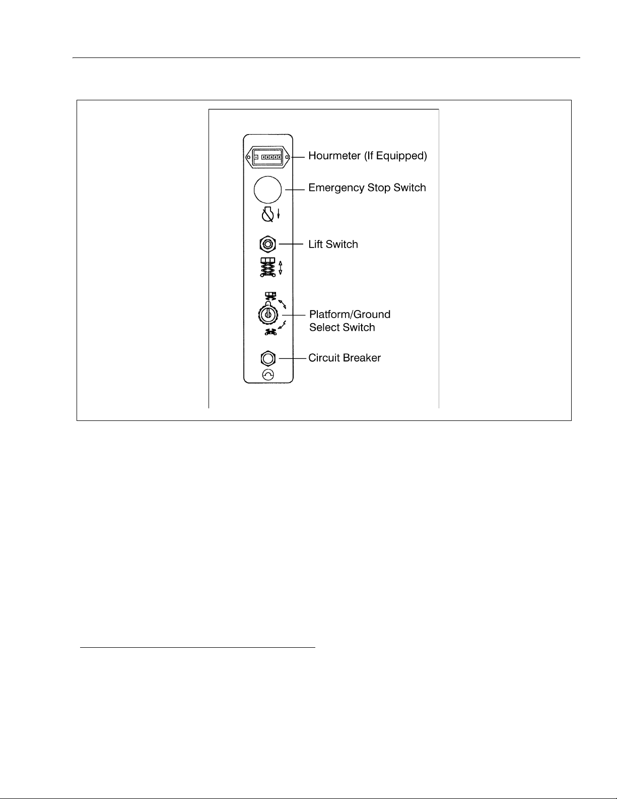
3-1. Ground Control Station - Model 1532E3/1932E3 . . . . . . . . . . . . . . . . . . . . . . . . . . . . . . . . . . . . . .3-3
3-2. Ground Control Station - Models 2033E3/2046E3/2646E3/2658E3 . . . . . . . . . . . . . . . . . . . . . . .3-4
3-3. Platform Control Station - All Models . . . . . . . . . . . . . . . . . . . . . . . . . . . . . . . . . . . . . . . . . . . . . . . 3-5
3-4. Decal Installation - 1532E3 & 1932E3 Domestic/CSA (Sheet 1 of 2) . . . . . . . . . . . . . . . . . . . . . . .3-8
3-5. Decal Installation - 1532E3 & 1932E3 Domestic/CSA (Sheet 2 of 2) . . . . . . . . . . . . . . . . . . . . . . .3-9
3-6. Decal Installation - 1532E3 & 1932E3 Brazil (Sheet 1 of 2) . . . . . . . . . . . . . . . . . . . . . . . . . . . . . . 3-10
3-7. Decal Installation - 1532E3 & 1932E3 Brazil (Sheet 2 of 2) . . . . . . . . . . . . . . . . . . . . . . . . . . . . . . 3-11
3-8. Decal Installation - 1532E3 & 1932E3 Latin (Sheet 1 of 2) . . . . . . . . . . . . . . . . . . . . . . . . . . . . . . .3-12
3-9. Decal Installation - 1532E3 & 1932E3 Latin (Sheet 2 of 2) . . . . . . . . . . . . . . . . . . . . . . . . . . . . . . .3-13
3-10. Decal Installation - 1532E3 & 1932E3 China (Sheet 1 of 2) . . . . . . . . . . . . . . . . . . . . . . . . . . . . . .3-14
3-11. Decal Installation - 1532E3 & 1932E3 China (Sheet 2 of 2) . . . . . . . . . . . . . . . . . . . . . . . . . . . . . .3-15
3-12. Decal Installation - 1532E3 & 1932E3 Korea (Sheet 1 of 2) . . . . . . . . . . . . . . . . . . . . . . . . . . . . . .3-16
3-13. Decal Installation - 1532E3 & 1932E3 Korea (Sheet 2 of 2) . . . . . . . . . . . . . . . . . . . . . . . . . . . . . .3-17
3-14. Decal Installation - 1532E3 & 1932E3 Japan (Sheet 1 of 2) . . . . . . . . . . . . . . . . . . . . . . . . . . . . . .3-18
3-15. Decal Installation - 1532E3 & 1932E3 Japan (Sheet 2 of 2) . . . . . . . . . . . . . . . . . . . . . . . . . . . . . .3-19
3-16. Decal Installation - 2033E3/2046E3/2646E3 & 2658E3 - Domestic/CSA (Sheet 1 of 2) . . . . . . . .3-20
3-17. Decal Installation - 2033E3/2046E3/2646E3 & 2658E3 - Domestic/CSA (Sheet 2 of 2) . . . . . . . .3-21
3-18. Decal Installation - 2033E3/2046E3/2646E3 & 2658E3 - Brazil (Sheet 1 of 2) . . . . . . . . . . . . . . . .3-22
3-19. Decal Installation - 2033E3/2046E3/2646E3 & 2658E3 - Brazil (Sheet 2 of 2) . . . . . . . . . . . . . . . .3-23
3-20. Decal Installation - 2033E3/2046E3/2646E3 & 2658E3 - Latin (Sheet 1 of 2) . . . . . . . . . . . . . . . .3-24
3-21. Decal Installation - 2033E3/2046E3/2646E3 & 2658E3 - Latin (Sheet 2 of 2) . . . . . . . . . . . . . . . .3-25
3-22. Decal Installation - 2033E3/2046E3/2646E3 & 2658E3 - China (Sheet 1 of 2) . . . . . . . . . . . . . . .3-26
3-23. Decal Installation - 2033E3/2046E3/2646E3 & 2658E3 - China (Sheet 2 of 2) . . . . . . . . . . . . . . .3-27
3-24. Decal Installation - 2033E3/2046E3/2646E3 & 2658E3 - Korea (Sheet 1 of 2) . . . . . . . . . . . . . . .3-28
3-25. Decal Installation - 2033E3/2046E3/2646E3 & 2658E3 - Korea (Sheet 2 of 2) . . . . . . . . . . . . . . .3-29
3-26. Decal Installation - 2033E3/2046E3/2646E3 & 2658E3 - Japan (Sheet 1 of 2) . . . . . . . . . . . . . . . 3-30
3-27. Decal Installation - 2033E3/2046E3/2646E3 & 2658E3 - Japan (Sheet 2 of 2) . . . . . . . . . . . . . . . 3-31
4-1. Grade and Sideslope . . . . . . . . . . . . . . . . . . . . . . . . . . . . . . . . . . . . . . . . . . . . . . . . . . . . . . . . . . .4-4
4-2. E3 Tie Down . . . . . . . . . . . . . . . . . . . . . . . . . . . . . . . . . . . . . . . . . . . . . . . . . . . . . . . . . . . . . . . . . .4-6
4-3. Lifting Chart . . . . . . . . . . . . . . . . . . . . . . . . . . . . . . . . . . . . . . . . . . . . . . . . . . . . . . . . . . . . . . . . . . . 4-7
LIST OF TABLES
TABLE NO. TITLE PAGE NO.
1-1 Minimum Safe Approach Distances (M.S.A.D.) . . . . . . . . . . . . . . . . . . . . . . . . . . . . . . . . . . . . . . . 1-3
6-1 Inspection and Repair Log . . . . . . . . . . . . . . . . . . . . . . . . . . . . . . . . . . . . . . . . . . . . . . . . . . . . . . .6-1
ii – JLG Sizzor – 3120761
Page 9
SECTION 1 - SAFETY PRECAUTIONS
SECTION 1. SAFETY PRECAUTIONS
1.1 GENERAL
This section outlines the necessary precautions for proper
and safe machine usage and maintenance. For proper
machine use, it is mandatory that a daily routine is established based on the content of this manual. A maintenance program, using the information provided in this
manual and the Service and Maintenance Manual, must
also be established by a qualified person and followed to
ensure that the machine is safe to operate.
The owner/user/operator/lessor/lessee of the machine
should not operate this machine until this manual has
been read, training is accomplished, and operation of the
machine has been completed under the supervision of an
experienced and qualified operator.
If there are any questions with regard to safety, training,
inspection, maintenance, application, and operation,
please contact JLG Industries, Inc. (“JLG”).
FAILURE TO COMPLY WITH THE SAFETY PRECAUTIONS LISTED
IN THIS MANUAL COULD RESULT IN MACHINE DAMAGE, PROPERTY DAMAGE, PERSONAL INJURY OR DEATH.
1.2 PRE-OPERATION
Operator Training and Knowledge
• Read and understand this manual before operating the
machine.
• Do not operate this machine until complete training is
performed by authorized persons.
• Only authorized and qualified personnel can operate
the machine.
• Read, understand, and obey all DANGERS, WARNINGS, CAUTIONS, and operating instructions on the
machine and in this manual.
• Use the machine in a manner which is within the scope
of its intended application set by JLG.
• All operating personnel must be familiar with the emergency controls and emergency operation of the
machine as specified in this manual.
• Read, understand, and obey all applicable employer,
local, and governmental regulations as they pertain to
operation of the machine.
Workplace Inspection
• The operator is to take safety measures to avoid all
hazards in the work area prior to machine operation.
• Do not swing turntable or raise the platform while on
trucks, trailers, railway cars, floating vessels, scaffolds
or other equipment unless approved in writing by JLG.
• Do not operate the machine in hazardous environments unless approved for that purpose by JLG.
• Be sure that the ground conditions are able to support
the maximum load shown on the decals located on the
machine.
• This machine can be operated in temperatures of 0
o
to 104
F (-20o C to 40o C). Consult JLG for operation
outside this range.
o
F
3120761 – JLG Lift – 1-1
Page 10

SECTION 1 - SAFETY PRECAUTIONS
Machine Inspection
• Before machine operation, perform inspections and
functional checks. Refer to Section 2 of this manual for
detailed instructions.
• Do not operate this machine until it has been serviced
and maintained according to requirements specified in
the Service and Maintenance Manual.
• Be sure all safety devices are operating properly. Modification of these devices is a safety violation.
• Do not operate any machine on which safety or
instruction placards or decals are missing or illegible.
• Avoid any buildup of debris on the platform floor. Keep
mud, oil, grease, and other slippery substances from
footwear and platform floor.
1.3 OPERATION
General
• Do not use the machine for any purpose other than
positioning personnel, their tools, and equipment.
• Never operate a machine that is not working properly.
If a malfunctions occurs, shut down the machine.
• Never slam a control switch or lever through neutral to
an opposite direction. Always return switch to neutral
and stop before moving the switch to the next function.
Operate controls with slow and even pressure.
• Hydraulic cylinders should never be left fully extended
or fully retracted before shutdown or for long periods of
time.
• Do not allow personnel to tamper with or operate the
machine from the ground with personnel in the platform, except in an emergency.
• Do not carry materials directly on platform railing
unless approved by JLG.
• When two or more persons are in the platform, the
operator shall be responsible for all machine operations.
• Always ensure that power tools are properly stowed
and never left hanging by their cord from the platform
work area.
• Supplies or tools which extend outside the platform are
prohibited unless approved by JLG.
• Do not assist a stuck or disabled machine by pushing,
pulling, or by using machine functions. Only pull the
unit from the tie-down lugs on the chassis.
• Stow elevating assembly and shut off all power before
leaving machine.
Trip and Fall Hazards
• When operating a boom lift, occupants in the platform
must wear a full body harness with a lanyard attached
to an authorized lanyard anchorage point. When operating a scissor lift or vertical mast lift, JLG recommends
wearing a full body harness. Attach only one (1) lanyard per lanyard anchorage point.
• Before operating the machine, make sure all gates are
closed and fastened or in their proper position.
• Keep both feet firmly positioned on the platform floor at
all times. Never use ladders, boxes, steps, planks, or
similar items on platform to provide additional reach.
• Never use the elevating assembly to enter or leave the
platform.
• Use extreme caution when entering or leaving platform. Be sure that the platform is fully lowered. Face
the machine, maintain “three point contact” with the
machine, using two hands and one foot or two feet and
one hand during entry and exit.
• Check orientation of directional arrows on chassis
before driving. The direction of drive and steer may be
opposite from normal operation based upon orientation of chassis.
1-2 – JLG Lift – 3120761
Page 11
SECTION 1 - SAFETY PRECAUTIONS
• Platform-to-structure transfers at elevated positions are
discouraged. Where transfer is necessary, enter/exit
through the gate only with the platform within 1 foot
(0.3m) of a safe and secure structure. 100% tie-off is
also required in this situation using two lanyards. One
lanyard must be attached to the platform with the second lanyard attached to the structure. The lanyard connected to the platform must not be disconnected until
the transfer to the structure is safe and complete.
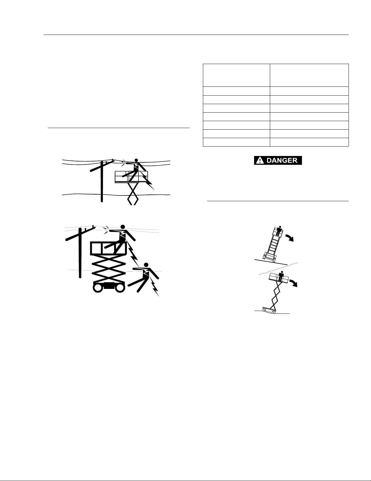
Electrocution Hazards
• This machine is not insulated and does not provide
protection from contact or proximity to electrical current.
Table 1-1.Minimum Safe Approach Distances (M.S.A.D.)
Voltage Range
(Phase to Phase)
0 to 300V AVOID CONTACT
Over 300V to 50 KV 3 (10)
Over 50KV to 200 KV 5 (15)
Over 200 KV to 350 KV 6(20)
Over 350 KV to 500 KV 8 (25)
Over 500 KV to 750 KV 11 (35)
Over 750 KV to 1000 KV 14 (45)
DO NOT MANEUVER MACHINE OR PERSONNEL INSIDE PROHIBITED ZONE (MSAD). ASSUME ALL ELECTRICAL PARTS AND WIRING ARE ENERGIZED UNLESS KNOWN OTHERWISE.
MINIMUM SAFE APPROACH
DISTANCE
in Meters (Feet)
Tipping Hazards
• The user should be familiar with the surface before
driving. Do not exceed the allowable sideslope and
grade while driving..
• Maintain safe distance from electrical lines, apparatus,
or any energized (exposed or insulated) parts according to the Minimum Safe Approach Distance (MSAD)
as shown in Table 1-1.
• Allow for machine movement and electrical line swaying.
• Do not elevate platform or drive with platform elevated
while on a sloping, uneven, or soft surface.
• Before driving on floors, bridges, trucks, and other surfaces, check allowable capacity of the surfaces.
• Never exceed the maximum platform capacity. Distribute loads evenly on platform floor.
3120761 – JLG Lift – 1-3
Page 12

SECTION 1 - SAFETY PRECAUTIONS
• Do not raise the platform or drive from an elevated
position unless the machine is on firm, level surfaces
and evenly supported.
• Keep the chassis of the machine at least 2 ft. (0.6m)
from holes, bumps, drop-offs, obstructions, debris,
concealed holes, and other potential hazards on the
floor/surface unless approved by JLG.
• Never attempt to use the machine as a crane. Do not
tie-off machine to any adjacent structure.
• Do not operate the machine when wind conditions
exceed the maximum allowable wind speed.
• Do not increase the surface area of the platform or the
load. Increase of the area exposed to the wind will
decrease stability.
• Do not increase the platform size with unauthorized
deck extensions or attachments.
• If elevating assembly or platform is in a position that
one or more wheels are off the ground, all persons
must be removed before attempting to stabilize the
machine. Use cranes, forklift trucks, or other appropriate equipment to stabilize machine and remove personnel.
Crushing and Collision Hazards
• Approved head gear must be worn by all operating
and ground personnel.
• Keep hands and limbs out of the elevating assembly
during operation.
• Check work area for clearances overhead, on sides,
and bottom of platform when lifting or lowering platform, and driving.
• Limit travel speed according to conditions of ground
surface, congestion, visibility, slope, location of personnel, and other factors which may cause collision or
injury to personnel.
• Be aware of stopping distances in all drive speeds.
When driving in high speed, switch to low speed
before stopping. Travel grades in low speed only.
• Do not use high speed drive in restricted or close quarters or when driving in reverse.
• Exercise extreme caution at all times to prevent obstacles from striking or interfering with operating controls
and persons in the platform.
• Be sure that operators of other overhead and floor level
machines are aware of the aerial work platform’s presence. Disconnect power to overhead cranes.
• Warn personnel not to work, stand, or walk under a
raised platform. Position barricades on floor if necessary.
1.4 TOWING, LIFTING, AND HAULING
• Never allow personnel in platform while towing, lifting,
or hauling.
• This machine should not be towed, except in the event
of emergency, malfunction, power failure, or loading/
unloading. Refer to the Emergency Procedures section
of this manual for emergency towing procedures.
• The platform must be completely empty of tools.
• When lifting machine, lift only at designated areas of
the machine. Lift with lifting equipment of adequate
capacity.
• Refer to the Machine Operation section of this manual
for lifting information.
1.5 ADDITIONAL HAZARDS / SAFETY
• Do not use machine as a ground for welding.
• Do not refuel the machine with the engine running.
• Battery fluid is highly corrosive. Avoid contact with skin
and clothing at all times.
• Charge batteries only in a well ventilated area.
• During operation, keep all body parts inside platform
railing.
• Use elevating assembly functions, not the drive function to position the platform close to obstacles
• Always post a lookout when driving in areas where
vision is obstructed.
• Keep non-operating personnel at least 1.8m (6 ft.)
away from machine during all driving operations.
1-4 – JLG Lift – 3120761
Page 13

SECTION 2 - MACHINE PREPARATION AND INSPECTION
IMPORTANT
SECTION 2. MACHINE PREPARATION AND INSPECTION
2.1 GENERAL
This section provides the necessary information needed
by those personnel that are responsible to place the
machine in operation readiness, and lists checks that are
performed prior to use of the machine. It is important that
the information contained in this section be read and
understood before any attempt is made to operate the
machine. Ensure that all the necessary inspections have
been completed successfully before placing the machine
into service. These procedures will aid in obtaining maximum service life and safe operation.
SINCE THE MACHINE MANUFACTURER HAS NO DIRECT CONTROL OVER THE FIELD INSPECTION AND MAINTENANCE,
SAFETY IS THE RESPONSIBILITY OF THE OWNER/OPERATOR.
2.2 PREPARATION FOR USE
Before a new machine is put into operation it must be
carefully inspected for any evidence of damage resulting
from shipment and inspected periodically thereafter as
outlined in the Delivery and Frequent Inspection. The unit
should be thoroughly checked for hydraulic leaks during
initial start-up and run. A check of all components should
be made to assure their security.
All preparations necessary to place the machine in operation readiness status are the responsibility of management personnel. Preparation requires good common
sense, (i.e. lift works smoothly and brakes operate properly) coupled with a series of visual inspections. The mandatory requirements are given in the Daily Walk Around
Inspection.
It should be assured that the items appearing in the Delivery and Periodic Inspection and Functional Check are
complied with prior to putting the machine into service.
The following checklist provides a systematic inspection
to assist in detecting defective, damaged, or improperly
installed parts. The checklist denotes the items to be
inspected and conditions to examine. Frequent inspection
shall be performed monthly or more often when required
by environment, severity, and frequency of usage.
Frequent inspection shall be performed every 3 months or
150 hours whichever comes first, or more often when
required by environment, severity, and frequency of
usage.
Handrail Assemblies
Properly installed; no loose or missing parts; no visible
damage.
Platform Assembly
No visible damage; free of dirt and debris.
Sizzor Arms
No visible damage, abrasions and/or distortions.
Electrical Cable
No visible damage; properly secured.
Pivot Pins
No loose or missing retaining hardware; no visible damage; no evidence of pin or bushing wear.
Lift Cylinder
No rust, nicks, scratches or foreign material on piston rod;
no leakage.
Frame
No visible damage; loose or missing hardware (top and
underside).
2.3 DELIVERY AND FREQUENT INSPECTION
NOTE: This machine requires periodic safety and mainte-
NOTE: An annual inspection shall be performed on the
3120761 – JLG Sizzor – 2-1
nance inspections by a JLG Dealer. A decal located
on the frame provides a place to record (stamp)
inspection dates. Check decal and notify dealer if
inspection is overdue.
aerial platform no later than thirteen (13) months
from the date of the prior annual inspection. The
inspection shall be performed by person(s) certified
as a mechanic on the specific make and model of
the aerial platform.
Tire and Wheel Assemblies
No loose or missing lug nuts; no visible damage; check
drive hoses for damage.
Sliding Wear Pad Blocks
No excessive wear.
Hydraulic Oil Supply
Operate lift function through one complete cycle before
checking oil level. Oil level should read at full mark, or
within 1/2" below full mark, on side of hydraulic tank (all
systems shut down, machine in stowed position); no visible oil leakage on the ground.
Page 14
SECTION 2 - MACHINE PREPARATION AND INSPECTION
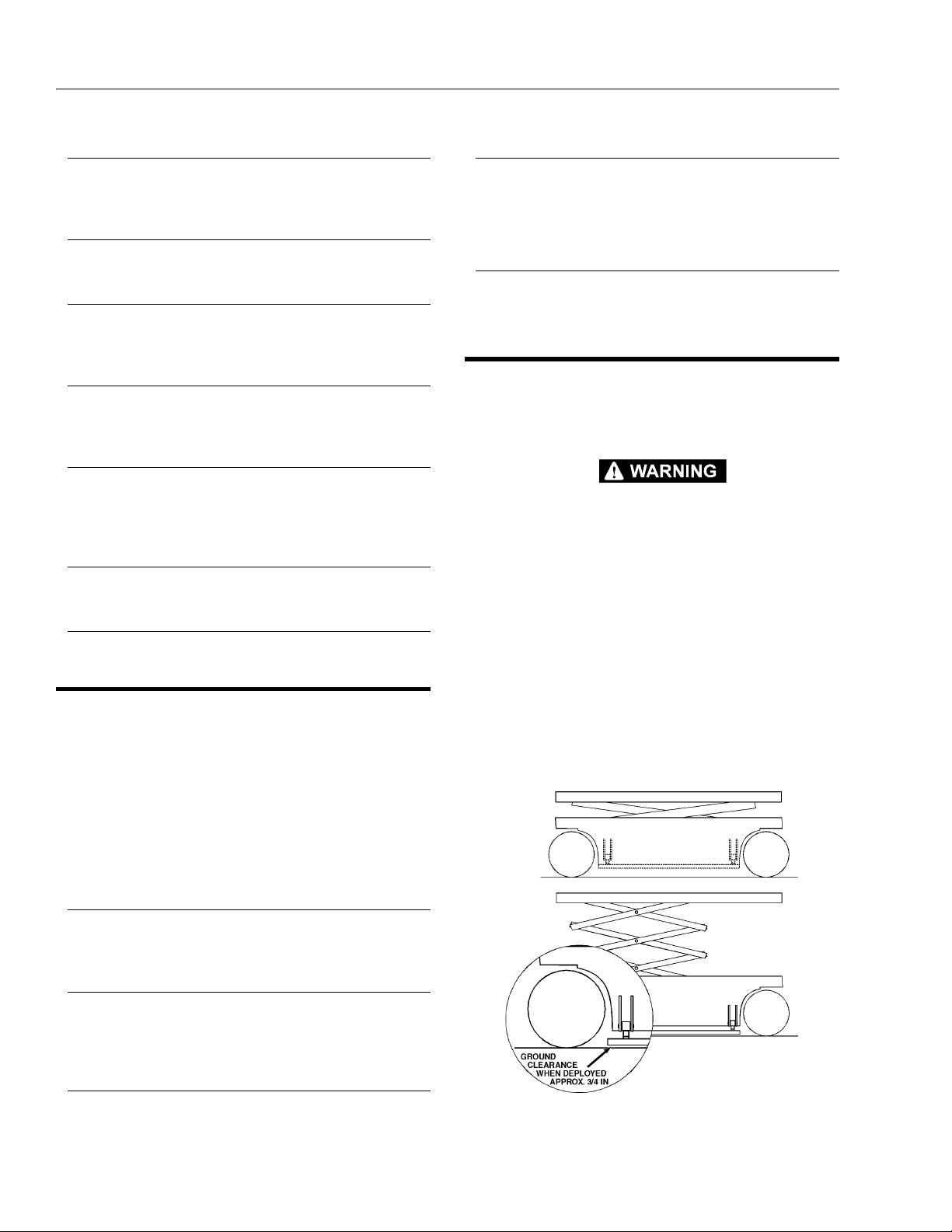
Figure 2-1. Pothole Protection System Operation
Steer Cylinder
No rust, nicks, scratches or foreign material on piston rod;
no leakage.
Steer Linkage
No loose or missing parts; no visible damage.
Front Spindle Assemblies
No excessive wear; no damage; evidence of proper lubrication.
Control Boxes (Platform and Ground)
Switches operable; no visible damage; placards secure
and legible; controller operable; no visible damage.
Batteries
Proper electrolyte level; cable connections tight; no visible
damage; no corrosion at battery cable connections.
Ensure batteries are fully charged.
Motor/Pump Unit and Valves
No leakage; units secure.
Platform Placards
No visible damage; placards secure and legible.
Machine Log
Ensure a machine operating record or log is kept. Check
to see that it is current and that no entries have been left
uncleared, leaving machine in an unsafe condition for
operation.
Daily Lubrication
For those items pointed out in the Daily Walk-Around
Inspection requiring daily lubrication, refer to the Lubrication Chart for specific requirements.
2.5 DAILY FUNCTIONAL CHECK
Perform functional checks in accordance with the Daily
Functional Check before attempting to operate the
machine.
TO AVOID INJURY DO NOT OPERATE A MACHINE UNTIL ALL
MALFUNCTIONS HAVE BEEN CORRECTED. USE OF A MALFUNCTIONING MACHINE IS A SAFETY VIOLATION.
A functional check of all systems should be performed,
under no load, once the walk-around inspection is complete, in an area free of overhead and ground level
obstructions. Perform pre-load functional check in accordance with the following procedure:
1. Ensure batteries are fully charged.
2.4 DAILY WALK-AROUND INSPECTION
It is the users responsibility to inspect the machine before
the start of each workday. It is recommended that each
user inspect the machine before operation, even if the
machine has already been put into service under another
user. This Daily Walk-Around Inspection, Figure 2-2, is the
preferred method of inspection.
In addition to the Daily Walk-Around Inspection, be sure to
include the following as part of the daily inspection:
Overall Cleanliness
Check all standing surfaces for oil, fuel and hydraulic oil
spillage and foreign objects. Ensure overall cleanliness.
Placards
Keep all information and operating placards clean and
unobstructed. Cover when spray painting or shot blasting
to protect legibility.
Operators and Safety Manual
Ensure a copy of this manual is enclosed in the manual
storage box.
2. Raise and lower platform several times. Check for
smooth elevation and lowering. Check for High
Drive cut-out as platform begins to raise. Check that
pothole protection system is deployed when platform is raised and that actuating rollers are in contact with the connecting bar.
2-2 – JLG Sizzor – 3120761
Page 15

SECTION 2 - MACHINE PREPARATION AND INSPECTION
3. Drive forward and reverse, check for proper operation.
4. Check that drive brake holds when machine is
driven up a hill, not to exceed rated gradeability, and
stopped.
NOTE: For units equipped with optional tilt cutout, verify that
drive and lift functions are cutout when the platform
is elevated and the tilt alarm is activated.
5. Steer left and right. Check for proper operation.
6. Check fluid level on hydraulic oil reservoir. Refer to
the Lubrication Chart.
2.6 TORQUE REQUIREMENTS
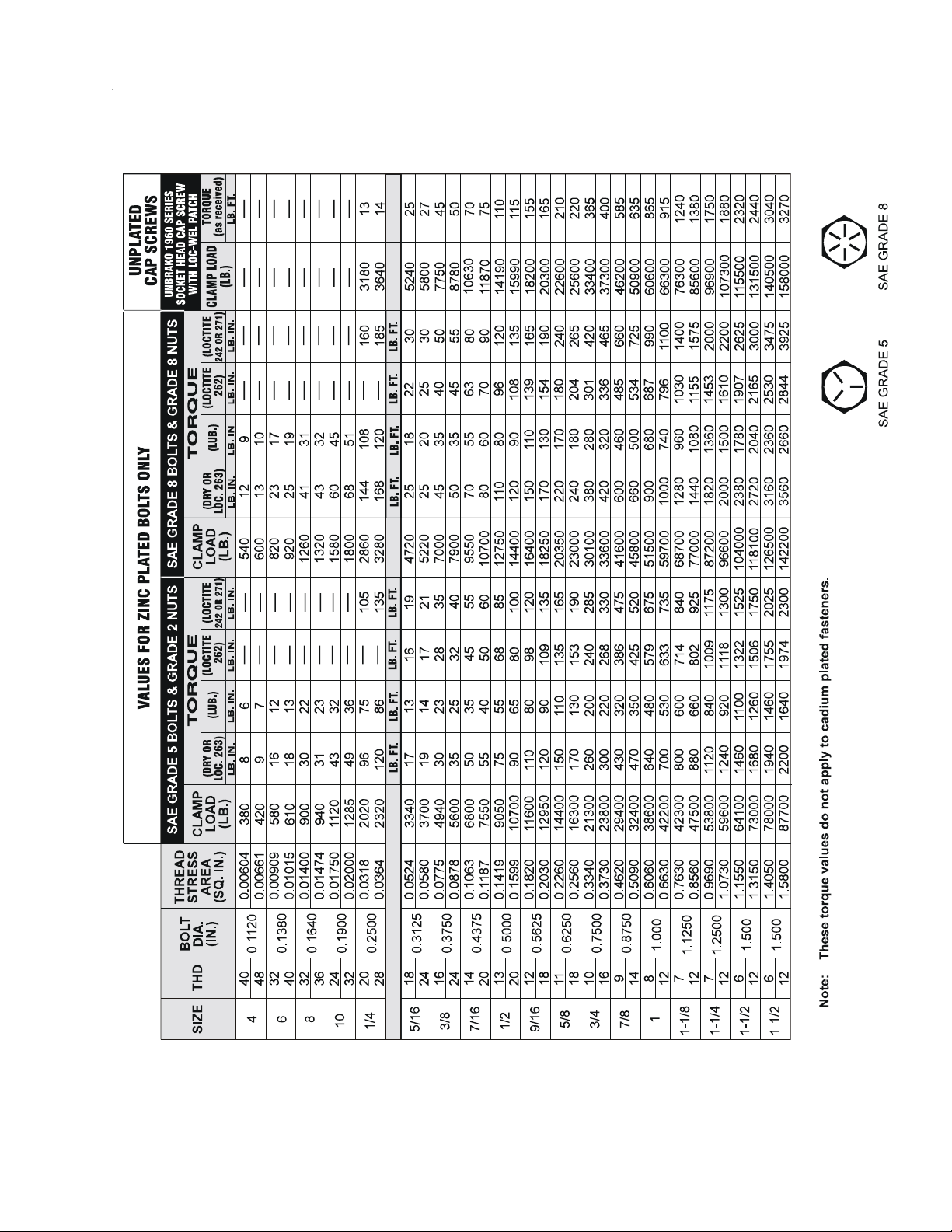
The Torque Chart consists of standard torque values
based on bolt diameter and grade, also specifying dry
and wet torque values in accordance with recommended
shop practices. This chart is provided as an aid to the
operator in the event he/she notices a condition that
requires prompt attention during the walk-around inspection or during operation until the proper service personnel
can be notified. The Service and Maintenance Manual
provides specific torque values and periodic maintenance
procedures with a listing of individual components. Utilizing this Torque Chart in conjunction with the preventive
maintenance procedures in the Service and Maintenance
Manual will enhance safety, reliability and performance of
the machine.
2.7 BATTERY CHARGING
At the end of the work day, the batteries should be
charged for the next days work. Position the Emergency
Stop switch to OFF. Prior to charging, be sure electrolyte
covers plates. Connect the battery charger to a properly
grounded receptacle using a suitable extension cord. Set
the battery charger timer switch, if equipped, for the
desired charging time. After charging, check the electrolyte level of the batteries and adjust accordingly. Add distilled water only to batteries. A fully charged battery will
have a specific gravity of between 1.260 - 1.275 on a
hydrometer.
WHEN ADDING DISTILLED WATER TO THE BATTERIES, A NONMETALLIC CONTAINER AND/OR FUNNEL MUST BE USED. ADD
WATER ONLY TO LEVEL INDICATOR OR 3/8 INCH (0.95 CM)
ABOVE SEPARATORS.
NO OPEN FLAMES OR SMOKING WHEN CHARGING BATTERIES.
CHARGE BATTERIES ONLY IN A WELL VENTILATED AREA.
ENSURE THAT BATTERY ACID DOES NOT COME INTO CONTACT
WITH SKIN OR CLOTHING.
NOTE: Be sure to disconnect and store any extension cords
after charging batteries and before putting machine
into service.
To avoid electrolyte overflow, add distilled water to
batteries after charging.
3120761 – JLG Sizzor – 2-3
Page 16
SECTION 2 - MACHINE PREPARATION AND INSPECTION
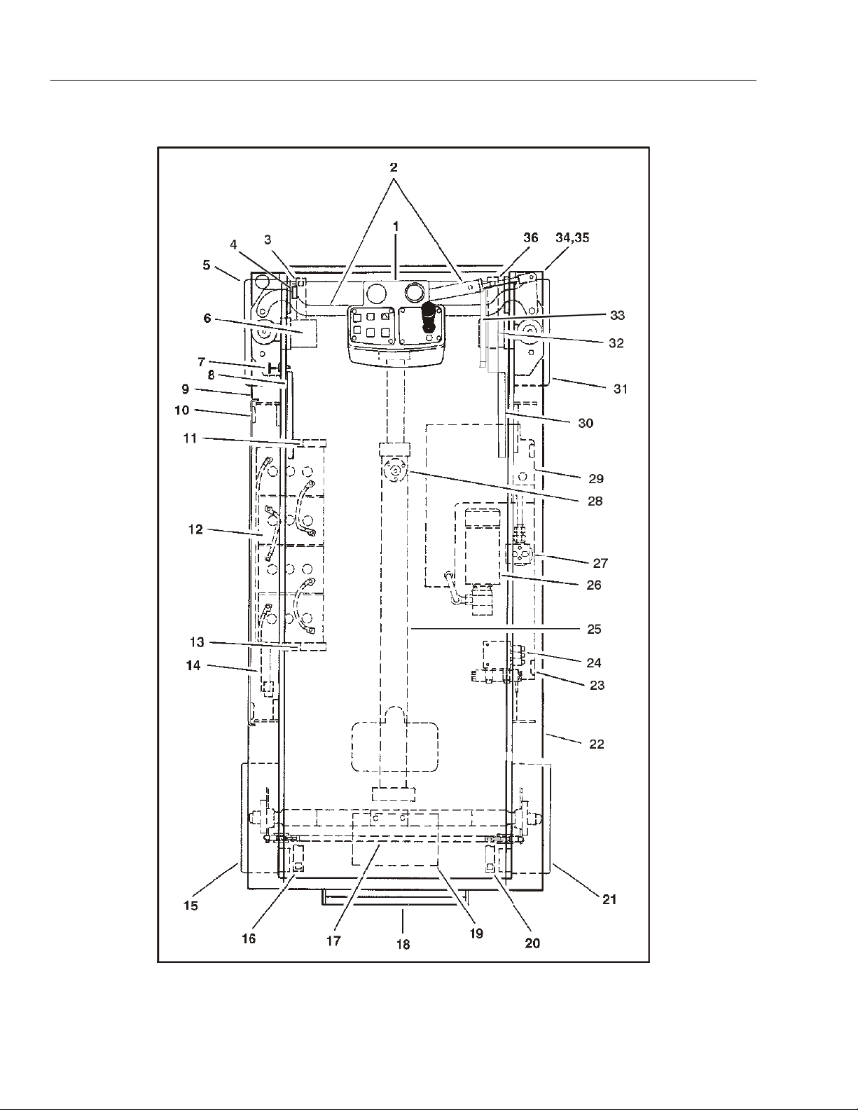
Figure 2-2. Daily Walk-Around Inspection Diagram
2-4 – JLG Sizzor – 3120761
Page 17
SECTION 2 - MACHINE PREPARATION AND INSPECTION
General
Begin the “Walk-Around Inspection” at Item 1, as
noted on the diagram. Continue to the right (counterclockwise viewed from top) checking each item in
sequence for the conditions listed in the “WalkAround inspection Checklist.”
TO AVOID INJURY DO NOT OPERATE MACHINE UNTIL ALL
MALFUNCTIONS HAVE BEEN CORRECTED. USE OF A MALFUNCTIONING MACHINE IS A SAFETY VIOLATION.
TO AVOID POSSIBLE INJURY, BE SURE MACHINE POWER IS
“OFF” DURING “WALK-AROUND INSPECTION.”
NOTE: Do not overlook visual inspection of chassis
underside. Checking this area often results in
discovery of conditions which could cause
extensive machine damage.
1. Platform Controls - Properly secured; no loose
or missing parts; no visible damage to control
box or controller (joystick). Placards secure and
legible; control markings legible; manual in
manual storage box.
2. Steer Cylinder and Linkage - Properly secured;
no loose or missing parts; no visible damage;
no evidence of steer cylinder leakage.
3. Scissor Arms and Sliding Wear Pads - Properly
secured; no visible damage; no loose or missing parts.
4. High Drive Limit Switch - Properly secured; no
visible damage; no loose or missing parts.
5. Steer/Drive Wheel and Tire Assembly, Left Front
- Properly secured; no loose or missing lug
nuts; no visible damage; check drive hoses.
6. Drive Motor, Left Front - Properly secured; no
visible damage; no evidence of leakage.
7. Manual Descent Cable and Pull Handle - Properly secured; no loose or missing parts; no visible damage.
8. Powered Deck Extension Cylinder (If Equipped)
- Properly secured; no visible damage; no
loose or missing parts; no evidence of leakage.
9. Pothole Protection System - Support bar, rollers, limit switches, springs and links properly
secured; no visible damage; no loose or missing parts.
10. Compartment Cover and Latches - Cover and
latches in working condition; properly secured;
no loose or missing parts.
11. Machine Controller (1532E and 1932E) - Properly secured; no visible damage; no loose or
broken wiring.
12. Battery Installation - Proper electrolyte level;
cables secure; no damage or corrosion. Holddowns secure.
13. Machine Controller (2033E, 2046E, 2646E and
2658E) - Properly secured; no visible damage;
no loose or broken wiring.
14. Ground Controls - Properly secured; no visible
damage; switches operable; placards secure
and legible.
15. Wheel and Tire Assembly, Left Rear - Properly
secured; no loose or missing lug nuts; no visible damage.
16. Scissor Arms and Sliding Wear Pads - Properly
secured; no visible damage; no loose or missing parts.
17. Parking Brake - No loose or missing parts; no
visible damage; no cylinder leakage.
18. Ladder - Properly secured; no visible damage;
no loose or missing hardware.
19. Battery Charger - No visible damage; properly
secured.
20. Scissor Arms and Sliding Wear Pads - Properly
secured; no visible damage; no loose or missing parts.
21. Wheel and Tire Assembly, Right Rear - Properly
secured; no loose or missing lug nuts; no visible damage.
22. Pothole Protection System - Support bar, rollers, limit switches and links properly secured;
no visible damage; no loose or missing parts.
23. Compartment Cover and Latches - Cover and
latches in working condition; properly secured;
no visible damage; no loose or missing parts.
24. Control Valve Installation - No loose or missing
parts; no evidence of leakage. No unsupported
wires or hoses; no damaged or broken wires.
25. Lift Cylinder - Properly secured; no visible damage; no loose or missing parts; no evidence of
leakage.
Figure 2-2. Daily Walk-Around Inspection Points (Sheet 2 of 3)
3120761 – JLG Sizzor – 2-5
Page 18

SECTION 2 - MACHINE PREPARATION AND INSPECTION
26. Motor/Pump Unit - Properly secured; no visible
damage; no evidence of hydraulic leakage.
27. Hydraulic Fliter - No visible damage; properly
secured; no evidence of leakage
28. Tilt Switch - Properly secured; no loose or missing parts; no visible damage; no loose or broken
wires.
29. Hydraulic Reservoir - No visible damage; no
loose or missing parts; no evidence of leakage.
Recommended hydraulic fluid level on side of
tank. Breather cap secure and working.
30. Powered Deck Extension Cylinder (If Equipped) Properly secured; no visible damage; no loose or
missing parts; no evidence of leakage.
31. Steer/Drive Wheel and Tire Assembly, Right Front
- Properly secured; no loose or missing lug nuts;
no visible damage; check drive hoses.
32. Drive Motor, Right Front - Properly secured;no
visible damage; no evidence of leakage.
33. Safety Prop - Properly secured;no loose or missing parts; no visible damage.
34. Handrail Installation - All railings securely
attached; no visible damage;no missing parts;
chain improper working order. If equipped,
access gate properly secured and in good working order.
35. Platform Assembly - No loose or missing parts;no
visible damage; platform deck extension operates properly.
36. Scissor Arms and Sliding Wear Pads - Properly
secured;no visible damage; no loose or missing
parts.
37. (Not Shown on Illustration) Valves, Valve Fittings,
Hosing and Tubing - Properly secured; no loose
or missing parts; no visible damage;no evidence
of leakage.
Figure 2-2. Daily Walk-Around Inspection Points (Sheet 3 of 3)
2-6 – JLG Sizzor – 3120761
Page 19
SECTION 2 - MACHINE PREPARATION AND INSPECTION
Figure 2-3. Torque Chart
3120761 – JLG Sizzor – 2-7
Page 20

SECTION 2 - MACHINE PREPARATION AND INSPECTION
This page left blank intentionally.
2-8 – JLG Sizzor – 3120761
Page 21

SECTION 3 - USER RESPONSIBILITIES AND MACHINE CONTROL
IMPORTANT
SECTION 3. USER RESPONSIBILITIES AND MACHINE CONTROL
3.1 GENERAL
SINCE THE MANUFACTURER HAS NO DIRECT CONTROL OVER
MACHINE APPLICATION AND OPERATION, CONFORMANCE WITH
GOOD SAFETY PRACTICES IN THESE AREAS IS THE RESPONSIBILITY OF THE USER AND HIS OPERATING PERSONNEL.
This section provides the necessary information needed
to understand control functions. Included in this section
are the operating characteristics and limitations, and functions and purposes of controls and indicators. It is important that the user read and understand the proper
procedures before operating the machine. These procedures will aid in obtaining optimum service life and safe
operation.
3.2 PERSONNEL TRAINING
The scissor lift is a personnel handling device; therefore, it
is essential that it be operated and maintained only by
authorized personnel who have demonstrated that they
understand the proper use and maintenance of the
machine. It is important that all personnel who are
assigned to and responsible for the operation and maintenance of the machine undergo a thorough training program and check out period in order to become familiar
with the characteristics prior to operating the machine.
6. The safest means to operate near overhead obstructions, other moving equipment, obstacles, depressions, holes, dropoffs, etc. on the supporting
surface.
7. Means to avoid the hazards of unprotected electrical
conductors.
8. Any other requirements of a specific job or machine
application.
Training Supervision
Training must be done under the supervision of a qualified
operator or supervisor in an open area free of obstructions
until the trainee has developed the ability to safely control
a scissor lift in congested work locations.
Operator Responsibility
The operator must be instructed that he has the responsibility and authority to shut down the machine in case of a
malfunction or other unsafe condition of either the
machine or the job site and to request further information
from his supervisor or JLG Distributor before proceeding.
NOTE: Manufacturer or Distributor will provide qualified per-
sons for training assistance with first unit(s) delivered
and thereafter as requested by user or his personnel.
Persons under the influence of drugs or alcohol or who
are subject to seizures, dizziness or loss of physical control must not be permitted to operate the machine.
Operator Training
Operator training must include instruction in the following:
1. Use and limitations of the platform controls, ground
controls, emergency controls and safety systems.
2. Knowledge and understanding of this manual and of
the control markings, instructions and warnings on
the machine itself.
3. Knowledge and understanding of all safety work
rules of the employer and of Federal, State and
Local Statutes, including training in the recognition
and avoidance of potential hazards in the work
place; with particular attention to the work to be performed.
4. Proper use of all required personnel safety equipment.
5. Sufficient knowledge of the mechanical operation of
the machine to recognize a malfunction or potential
malfunction.
3.3 OPERATING CHARACTERISTICS AND
LIMITATIONS
General
A thorough knowledge of the operating characteristics
and limitations of the machine is always the first requirement for any user, regardless of users experience with
similar types of equipment.
Placards
Important points to remember during operation are provided at the control stations by DANGER, WARNING,
CAUTION, IMPORTANT and INSTRUCTION placards. This
information is placed at various locations for the express
purpose of alerting personnel of potential hazards constituted by the operating characteristics and load limitations
of the machine. See foreword for definitions of the above
placards.
3120761 – JLG Sizzor – 3-1
Page 22

SECTION 3 - USER RESPONSIBILITIES AND MACHINE CONTROL
IMPORTANT
Capacities
Raising platform above horizontal with or without any load
in platform, is based on the following criteria:
1. Machine is positioned on a smooth, firm and level
surface.
2. Load is within manufacturers rated capacity.
3. All machine systems are functioning properly.
Stability
This machine, as originally manufactured by JLG and
operated within its rated capacity on a smooth, firm and
level supporting surface, provides a stable aerial platform
for all platform positions.
3.4 CONTROLS AND INDICATORS
The machine is equipped with control panels that use
symbols instead of words to indicate control functions.
Refer to Symbols figure for these symbols and their corresponding functions.
JLG SMART™ System
The machine is controlled by the JLG SMART™ System, a
24 volt, multiplex motor controller which works in conjunction with a joystick and several switches to operate all
machine functions.
Special operating characteristics of the JLG SMART™
System are noted where applicable. Special attention
should be paid to these operating characteristics, as they
may be somewhat different from those on previous JLG
machines.
IT IS A GOOD PRACTICE TO AVOID PRESSURE-WASHING ELECTRICAL/ELECTRONIC COMPONENTS. SHOULD PRESSUREWASHING BE UTILIZED TO WASH AREAS CONTAINING ELECTRICAL/ELECTRONIC COMPONENTS, JLG INDUSTRIES, INC. RECOMMENDS A MAXIMUM PRESSURE OF 750 PSI (52 BAR) AT A
MINIMUM DISTANCE OF 12 INCHES (30.5 CM) AWAY FROM THESE
COMPONENTS. IF ELECTRICAL/ELECTRONIC COMPONENTS
ARE SPRAYED, SPRAYING MUST NOT BE DIRECT AND BE FOR
BRIEF TIME PERIODS TO AVOID HEAVY SATURATION.
Battery Charger
The battery charger is located at the rear of the machine,
behind the ladder. The charger, which plugs into a standard 110 volt receptacle, is a 24 volt DC charger with an
output of 25 Amps. A built in automatic timer shuts down
charger operation when the batteries are fully charged. A
rocker switch circuit breaker is included to reset the
charger in the event of a loss of power. LEDs on the front
panel of the charger indicate the status of charger opera-
tion (Charge Complete, 80% Charge, Incomplete Charge,
Charger On, Abnormal Cycle).
Ground Control Station
DO NOT OPERATE FROM GROUND CONTROL STATION WITH
PERSONNEL IN THE PLATFORM EXCEPT IN AN EMERGENCY.
PERFORM AS MANY PRE-OPERATIONAL CHECKS AND INSPECTIONS FROM THE GROUND CONTROL STATION AS POSSIBLE.
REFER TO SECTION 2 FOR PRE-OPERATIONAL CHECKS AND
INSPECTIONS.
1. Power Selector Switch - A three position, key-operated Power Selector Switch supplies operating
power to the platform or ground controls, as
selected. When positioned to platform, the switch
provides power to the emergency stop switch at the
platform controls. When positioned to ground, the
switch provides power to the emergency stop switch
at the ground controls. With the Power Selector
Switch in the center off position, power is shut off to
both platform and ground controls.
NOTE: With the Power Selector Switch in the off position,
the key can be removed in order to incapacitate the
machine on the jobsite to avoid unauthorized use of
the machine.
With the Power Selector Switch positioned to
ground, ground functions will operate at low speed at
all times.
Low speed is the default speed for all functions.
When the platform is elevated, all functions operate
in creep speed only.
2. Emergency Stop Switch - A two-position, red,
mushroom-shaped Emergency Stop Switch, when
positioned to on with the Power Selector Switch
positioned to Ground, furnishes operating power to
the ground control station. In addition, the switch
can be used to turn off power to the function controls in the event of an emergency. Power is turned
on by pulling the switch out (ON), and is turned off
by pushing the switch in (off). Turning the Emergency Stop Switch off and then on again will reset
the Smart System if a system fault has occurred and
the machine has shut down.
3. Lift Switch - A three-position, momentary-contact
Lift control toggle switch provides raising and lowering of the platform when positioned to up or down.
4. Circuit Breaker - A push button reset 15 Amp circuit
breaker, located at the ground control panel, returns
interrupted power to the machine functions when
depressed.
5. Hourmeter (If Equipped) - The machine may be
equipped with an hourmeter to indicate the number
3-2 – JLG Sizzor – 3120761
Page 23
SECTION 3 - USER RESPONSIBILITIES AND MACHINE CONTROL
Figure 3-1. Ground Control Station - Model 1532E3/1932E3
of hours the machine has been operated. The hourmeter operates only when a machine function is
operating.
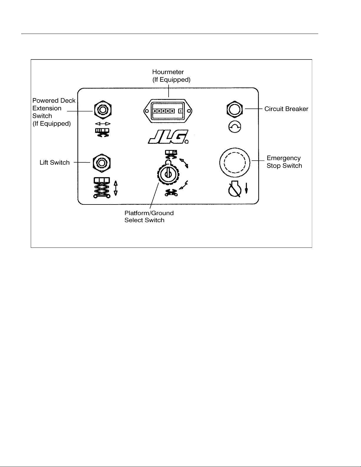
6. Powered Deck Extension Switch (If Equipped Models 2033E3, 2046E3, 2646E,3 and 2658E3 Only)
If the machine is equipped with either the 4 ft. (1.2
m) or 6 ft. (1.8 m) hydraulically-powered deck extension, this three-position, momentary contact toggle
switch provides extension or retraction of the deck
extension when positioned to extend or retract.
NOTE: If the machine is equipped with a powered deck
extension and the optional fold-down rails, the rails
must be in the upright position before retracting the
power deck extension.
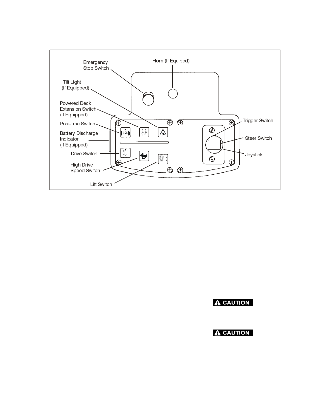
Platform Control Station
1. Emergency Stop Switch - A two-position, red,
mushroom-shaped emergency stop switch functions to provide power to the platform control station
and also to turn off power to the platform function
controls in the event of an emergency. With the
power selector switch positioned to platform, power
is turned on by pulling the switch out (on), and is
turned off by pushing the switch in (off). Turning the
emergency stop switch off and then on again will
reset the smart system if a system fault has occurred
and the machine has shut down.
2. Footswitch (Japanese Specification Only) - For
machines built to Japanese specifications, a footswitch is provided as part of the operating system.
The footswitch must be depresed in conjunction
with the red trigger switch on the joystick to operate
any funtion
3. Membrane Switch Panel - The function switches at
the platform control station are an integral part of a
membrane switch panel, which contains switches
for drive, high drive, lift, powered deck extension (if
equipped), and posi-trac, plus a red tilt indicator
light (if equipped). The drive, lift and powered deck
extension function switches have a small green light
indicator beside them which is illuminated when that
function is active. The function switch light indicators
will flash once or twice, then go out, when the platform emergency stop switch is turned on. If the light
indicators fail to flash or if they fail to stop flashing,
re-cycle the emergency stop switch. To activate the
drive, lift, and powered deck functions, press the
3120761 – JLG Sizzor – 3-3
Page 24
SECTION 3 - USER RESPONSIBILITIES AND MACHINE CONTROL
Figure 3-2. Ground Control Station - Models 2033E3/2046E3/2646E3/2658E3
applicable function switch, then activate the joystick
within three seconds to operate the function. If the
joystick is not activated within three seconds, power
is turned off to the function switch and the switch
must be pressed again. The posi-trac and high drive
functions are used in conjunction with the drive function. Do not try to operate the drive, lift, and powered
deck extension functions simultaneously. If the drive,
lift, and powered deck extension functions are
selected simultaneously, no function will operate. If
this occurs, pause, then press only one of the function switches to activate the function. Refer to the following paragraphs for more information about the
function switches.
4. Controller (Joystick) - The joystick controls three
functions: speed, direction, and powered deck
extension (if equipped). The joystick is used in conjunction with the trigger switch and controls the
drive, high drive, lift, and powered deck extension
switches to control speed and direction for the
selected function. The drive, high drive and posi-trac
functions may be operated simultaneously, but the
drive, lift, and powered deck extension functions
must be operated independently of each other. If the
drive, lift, and powered deck extension functions are
selected simultaneously, no function will operate. If
this occurs, pause, then press only one of the function switches to activate the function. To operate the
joystick, squeeze the red trigger switch, then position the joystick to forward or reverse, as desired. .
5. Steer Switch - The thumb-operated steer switch,
located on top of the joystick, works in conjunction
with the trigger switch and activates the steer wheels
in the direction the switch is moved (left or right).
6. Drive Switch - The drive switch, when used in conjunction with the joystick, provides for driving the
machine in forward or reverse. Drive is activated by
pressing the drive switch, in conjunction with the
trigger switch, and moving the joystick forward (forward) or backward (reverse). Drive speed is determined by the distance the joystick is moved forward
or backward. Increased drive speed is possible
when the high drive speed switch is pressed either
simultaneously with the drive switch or while operating the drive function. The drive switch is part of the
enable circuit, which provides power to the joystick
and the drive function for 3 seconds when the drive
3-4 – JLG Sizzor – 3120761
Page 25
SECTION 3 - USER RESPONSIBILITIES AND MACHINE CONTROL
Figure 3-3. Platform Control Station - All Models
switch is pressed. If the joystick is not activated
within 3 seconds, the drive switch must be pressed
again before activating the joystick. When the joystick is returned to the center off position, the operator has 3 seconds to re-activate the joystick or select
another function before power is removed by the
enable circuit. In addition, the posi-trac switch can
be engaged while operating the drive function to
give a more evenly distributed oil flow to each drive
motor. Do not try to operate the drive, lift, and powered deck extension functions simultaneously. If the
drive, lift, and powered deck extension functions are
selected simultaneously, no function will operate. If
this occurs, pause, then press only one of the function switches to activate the function.
NOTE: If the machine is equipped with the optional powered
deck extension, the Drive function is cut out when
the deck is extended with the platform raised above
the stowed position.
As an option, Models 2033E3 and 2646E3 may be
equipped for 1,000 lb. (455 kg) platform capacity.
When equipped for 1,000 lb. (455 kg) platform
capacity, Model 2033E3 cuts out the DRIVE function
at a platform height of 17 feet (5.2 m) and Model
2646E3 cuts out the DRIVE function at a platform
height of 19 feet (5.8 m).
The machine is equipped with a Pothole Protection
System which lowers automatically when the platform is raised. If the Pothole Protection System does
not fully lower, the Drive function is cut out until the
platform is completely lowered.
7. High Drive Speed Switch - The high drive speed
switch, when used in conjunction with the joystick
being operated in the drive mode, provides additional oil flow to the drive circuit for increased travel
speed. To operate high drive, depress the high drive
speed switch either simultaneously with the drive
switch or while operating the drive function.
DO NOT USE HIGH DRIVE SPEED WHEN DRIVING IN
CLOSE QUARTERS OR WHEN DRIVING IN REVERSE.
IF HIGH DRIVE IS SELECTED WHEN OIL TEMPERATURE IS VERY COLD (BELOW 40° F.) HIGH DRIVE WILL
NOT ENGAGE IMMEDIATELY. AS OIL WARMS (ABOVE
40° F.) IF HIGH DRIVE IS SELECTED, IT WILL ENGAGE
AUTOMATICALLY WHILE DRIVING.
3120761 – JLG Sizzor – 3-5
Page 26

SECTION 3 - USER RESPONSIBILITIES AND MACHINE CONTROL
IMPORTANT
NOTE: The High Drive Speed switch will cut-out when the
platform is raised above the stowed position, returning drive speed to low until the platform is lowered
completely.
DO NOT OPERATE MACHINE IF HIGH DRIVE SPEED OPERATES
WHEN PLATFORM IS RAISED ABOVE THE STOWED POSITION.
8. Lift Switch - The lift switch, when used in conjunction with the joystick, provides for raising and lowering the platform. Lift is activated by pressing the lift
switch and moving the joystick forward (lift up) or
backward (lift down). Lift up speed is determined by
the distance the joystick is moved forward. Lift down
speed is non-adjustable, and lift down is attained by
moving the joystick fully backward. The lift switch is
part of the enable circuit, which provides power to
the joystick and the lift function for 3 seconds when
the lift switch is pressed. If the joystick is not activated within 3 seconds, the lift switch must be
pressed again before activating the joystick. When
the joystick is returned to the center off position, the
operator has 3 seconds to re-activate the joystick or
select another function before power is removed by
the enable circuit. Do not try to operate the drive, lift,
and powered deck extension functions simultaneously. If the drive, lift, and powered deck extension functions are selected simultaneously, no
function will operate. If this occurs, pause, then
press only one of the function switches to activate
the function.
DO NOT LIFT DOWN WITHOUT COMPLETELY RETRACTING THE
PLATFORM EXTENSION.
10. Powered Deck Extension Switch (If Equipped Models 2033E3, 2046E3, 2646E3, and 2658E3
Only.) - If the machine is equipped with either the 4
ft. (1.2 m) or 6 ft. (1.8 m) hydraulically-powered deck
extension, this switch is used in conjunction with the
joystick to provide extension or retraction of the
powered deck extension. Powered deck extension
or retraction is activated by pressing the powered
deck extension switch and moving the joystick forward (EXTEND) or backward (RETRACT). The powered deck extension switch is part of the enable
circuit, which provides power to the joystick and the
powered deck extension function for 3 seconds
when the powered deck extension switch is
pressed. If the joystick is not activated within 3 seconds, the powered deck extension switch must be
pressed again before activating the joystick. When
the joystick is returned to the center off position, the
operator has 3 seconds to re-activate the joystick or
select another function before power is removed by
the enable circuit. Do not try to operate the powered
deck extension, drive, and lift functions simultaneously. If the powered deck extension, drive, and
lift functions are selected simultaneously, no function will operate. If this occurs, pause, then press
only one of the function switches to activate the
function.
11. Tilt Alarm Warning Horn - The Tilt Alarm Warning
Horn is activated by the Tilt Alarm Switch when the
chassis is on a severe slope (over 1.5° or 2.0°
depending on which tilt the machine is equipped
with). When the machine is equipped with a powered deck extension, the horn is activated when the
deck extension is being extended or retracted.
DO NOT ATTEMPT TO OPERATE THE LIFT AND DRIVE FUNCTIONS AT THE SAME TIME; NO FUNCTION WILL OPERATE AND IT
WILL BE NECESSARY TO RE-SELECT A SINGLE FUNCTION.
WHEN OPERATING LIFT DOWN MOVE THE JOYSTICK TO THE
FULL DOWN (FULLY BACKWARD) POSITION.
9. Positive Traction (Posi-Trac) Switch - This switch,
when pressed, activates a solenoid on the main control valve, forcing oil through a flow divider in the
drive circuit, maintaining hydraulic oil flow to both
drive motors for improved traction. The positive traction (Posi-trac) switch activates the positive traction
solenoid for a preset time when the positive traction
(Posi-trac) switch is pressed. Positive traction is
automatically de-activated after the preset time is
out. This function will only operate when the drive
function is activated.
3-6 – JLG Sizzor – 3120761
IF TILT ALARM IS ON WHEN PLATFORM IS RAISED, LOWER
PLATFORM COMPLETELY, THEN REPOSITION MACHINE SO
THAT IT IS LEVEL BEFORE RAISING PLATFORM.
12. Tilt Alarm Warning Light - A red warning light on
the membrane switch panel that illuminates when
the chassis is on a severe slope (over 1.5° or 2.0°
depending on which tilt the machine is equipped
with).
13. Horn (If Equipped) - This push-button switch, when
activated, permits the operator to warn jobsite personnel when the machine is operating in the area.
14. Battery Discharge Indicator (If Equipped) - The
battery discharge indicator is a gauge that provides
a visual indication of the condition of the batteries.
Page 27

SECTION 3 - USER RESPONSIBILITIES AND MACHINE CONTROL
3.5 PLACARDS AND DECALS
Read and understand all placards and decals. Do not
operate any machine on which DANGER, WARNING,
CAUTION, OR INSTRUCTION PLACARDS OR DECALS
ARE MISSING OR ILLEGIBLE. Replace placards and
decals if damaged, missing or illegible.
Decals are made of Lexan with a Pressure Sensitive Adhesive on back and a protective film on the front. Remove
the damaged decal and thoroughly clean the surface
before installing a new deacl. Simply peel off backing
paper and press decal on to the surface.
NOTE: Placards and decals can be ordered by using part
number and location found in the Parts Manual. (See
the folowing figures for the location of decals).
3120761 – JLG Sizzor – 3-7
Page 28

SECTION 3 - USER RESPONSIBILITIES AND MACHINE CONTROL
3252583
3252582
1532E3
1932E3
1702773
1703819
FWD
REV
1704132
1704131
1532E3
1932E3
1703817
1703818
1703812
1703818
1704132
1704131
1532E3
1932E3
1703816
3252588
1703817
1703817
1703817
1703814
1703813
1703823
1703819
1703788
1532E3
1703868
1932E3
3251813
3252588
1532E3
1703868
1932E3
3252191
CSA ONLY
Figure 3-4. Decal Installation - 1532E3 & 1932E3 Domestic/CSA (Sheet 1 of 2)
3-8 – JLG Sizzor – 3120761
Page 29
1704131
1532E3
1932E3
1704132
3252645
1703817
1703817
1703813
1703818
1702631
1703814
1704138
1703698
1703823
1704131
1532E3
1932E3
1704132
1703822
1704131
1532E3
1932E3
1704132
1703773
1702153
Figure 3-5. Decal Installation - 1532E3 & 1932E3 Domestic/CSA (Sheet 2 of 2)
SECTION 3 - USER RESPONSIBILITIES AND MACHINE CONTROL
3120761 – JLG Sizzor – 3-9
Page 30
SECTION 3 - USER RESPONSIBILITIES AND MACHINE CONTROL
3252583
3252582
1532E3
1932E3
1702773
1703819
FWD
REV
1704132
1704131
1532E3
1932E3
1703817
1703818
1703812
1703833
1704132
1704131
1532E3
1932E3
1703835
3252588
1703817
1703817
1703817
1703814
1703832
1703834
1703819
1703788
1532E3
1703868
1932E3
3252588
1532E3
1703868
1932E3
Figure 3-6. Decal Installation - 1532E3 & 1932E3 Brazil (Sheet 1 of 2)
3-10 – JLG Sizzor – 3120761
Page 31
1704131
1532E3
1932E3
1704132
3252645
1703817
1703817
1703832
1703833
1702631
1703814
1704138
1703831
1703834
1704131
1532E3
1932E3
1704132
1703822
1704131
1532E3
1932E3
1704132
1703773
1703961
Figure 3-7. Decal Installation - 1532E3 & 1932E3 Brazil (Sheet 2 of 2)
SECTION 3 - USER RESPONSIBILITIES AND MACHINE CONTROL
3120761 – JLG Sizzor – 3-11
Page 32
SECTION 3 - USER RESPONSIBILITIES AND MACHINE CONTROL
3252583
3252582
1532E3
1932E3
1702773
1703819
FWD
REV
1704132
1704131
1532E3
1932E3
1703817
1703818
1703812
1703841
1704132
1704131
1532E3
1932E3
1703843
3252588
1703817
1703817
1703817
1703814
1703840
1703842
1703819
1703788
1532E3
1703868
1932E3
3251813
3252588
1532E3
1703868
1932E3
Figure 3-8. Decal Installation - 1532E3 & 1932E3 Latin (Sheet 1 of 2)
3-12 – JLG Sizzor – 3120761
Page 33

1704131
1532E3
1932E3
1704132
3252645
1703817
1703817
1703840
1703841
1702631
1703814
1704138
1703839
1703842
1704131
1532E3
1932E3
1704132
1703822
1704131
1532E3
1932E3
1704132
1703773
1702552
Figure 3-9. Decal Installation - 1532E3 & 1932E3 Latin (Sheet 2 of 2)
SECTION 3 - USER RESPONSIBILITIES AND MACHINE CONTROL
3120761 – JLG Sizzor – 3-13
Page 34

SECTION 3 - USER RESPONSIBILITIES AND MACHINE CONTROL
3252583
3252582
1532E3
1932E3
1702773
1703819
FWD
REV
1704132
1704131
1532E3
1932E3
1703817
1703818
1703812
1704611
1704132
1704131
1532E3
1932E3
1704616
3252588
1703817
1703817
1703817
1703814
1704613
1704609
1703819
1703788
1532E3
1703868
1932E3
3251813
3252588
1532E3
1703868
1932E3
Figure 3-10. Decal Installation - 1532E3 & 1932E3 China (Sheet 1 of 2)
3-14 – JLG Sizzor – 3120761
Page 35

1703817
1703817
1703817
B
B
B
B
1703811
1703811
3251813
1703812
1703817
1703817
1703819
FWD
REV
1704611
1704133
2033E3
1704135
2046E3
1704136
1704137
2646E3
2658E3
2033E3
1704135
2046E3
1704136
1704137
2646E3
2658E3
1704609
1704613
3252584
2033E3
3252585
2046E3
3252586
3252587
2646E3
2658E3
1702773
1704277
1704133
1703694
3252591
2033E3/2046E3
2646E3/2658E3
Figure 3-11. Decal Installation - 1532E3 & 1932E3 China (Sheet 2 of 2)
SECTION 3 - USER RESPONSIBILITIES AND MACHINE CONTROL
3120761 – JLG Sizzor – 3-15
Page 36

SECTION 3 - USER RESPONSIBILITIES AND MACHINE CONTROL
3252583
3252582
1532E3
1932E3
1702773
1703819
FWD
REV
1704132
1704131
1532E3
1932E3
1703817
1703818
1703812
1703857
1704132
1704131
1532E3
1932E3
1703859
3252588
1703817
1703817
1703817
1703814
1703856
1703858
1703819
1703788
1532E3
1703868
1932E3
3251813
3252588
1532E3
1703868
1932E3
Figure 3-12. Decal Installation - 1532E3 & 1932E3 Korea (Sheet 1 of 2)
3-16 – JLG Sizzor – 3120761
Page 37

1704131
1532E3
1932E3
1704132
3252645
1703817
1703817
1703856
1703857
1702631
1703814
1704138
1703855
1703858
1704131
1532E3
1932E3
1704132
1703822
1704131
1532E3
1932E3
1704132
1703773
1703962
Figure 3-13. Decal Installation - 1532E3 & 1932E3 Korea (Sheet 2 of 2)
SECTION 3 - USER RESPONSIBILITIES AND MACHINE CONTROL
3120761 – JLG Sizzor – 3-17
Page 38
SECTION 3 - USER RESPONSIBILITIES AND MACHINE CONTROL
3252583
3252582
1532E3
1932E3
1702773
1703819
FWD
REV
1704132
1704131
1532E3
1932E3
1703817
1703818
1703812
1704282
1704132
1704131
1532E3
1932E3
1704807
3252588
1703817
1703817
1703817
1703814
1703848
1703850
1703819
1703788
1532E3
1703868
1932E3
3252588
1532E3
1703868
1932E3
Figure 3-14. Decal Installation - 1532E3 & 1932E3 Japan (Sheet 1 of 2)
3-18 – JLG Sizzor – 3120761
Page 39

1704131
1532E3
1932E3
1704132
3252749
1703817
1703817
1703848
1704282
1702631
1703814
1704138
1704281
1703850
1704131
1532E3
1932E3
1704132
1703822
1704131
1532E3
1932E3
1704132
1703773
1701621
Figure 3-15. Decal Installation - 1532E3 & 1932E3 Japan (Sheet 2 of 2)
SECTION 3 - USER RESPONSIBILITIES AND MACHINE CONTROL
3120761 – JLG Sizzor – 3-19
Page 40

SECTION 3 - USER RESPONSIBILITIES AND MACHINE CONTROL
1703788
1703814
1703811
1703811
1704138
1704211
1703819
1702153
3252645
1703817
1703817
1703822
2033E3
2046E3/2646E3/2658E3
1704133
2033E3
1704135
2046E3
1704136
1704137
2646E3
2658E3
1704133
2033E3
1704135
2046E3
1704136
1704137
2646E3
2658E3
1703813
1703694
1703823
1703698
2033E3/2046E3
3252591
2646E3/2658E3
1703694
2033E3/2046E3
3252591
2646E3/2658E3
1703816
1703821
FWD
REV
3252584
2033E3
3252585
2046E3
3252586
3252587
2646E3
2658E3
1703818
1704277
1702773
1702631
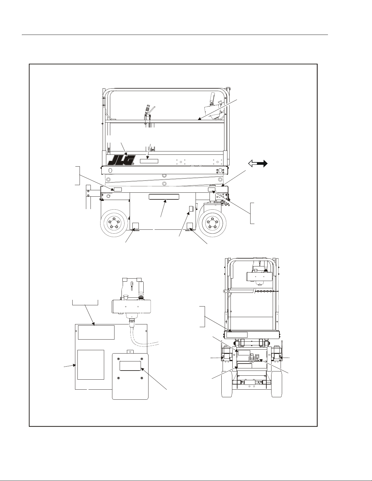
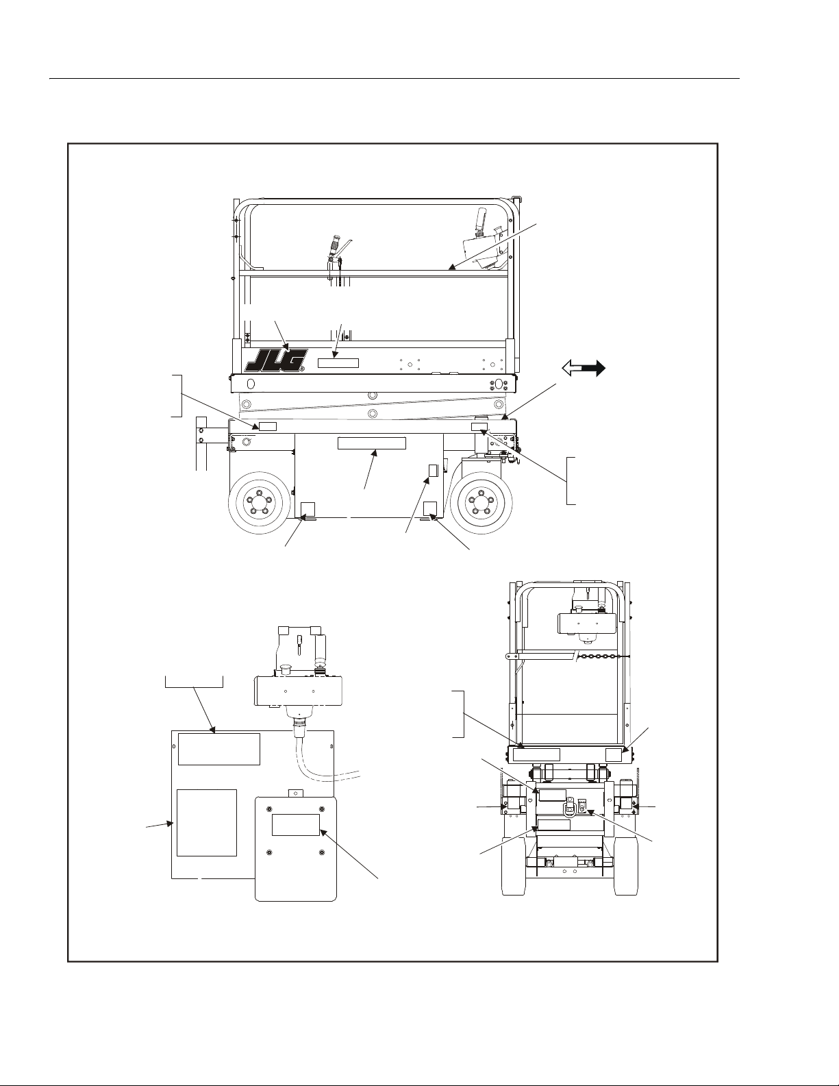
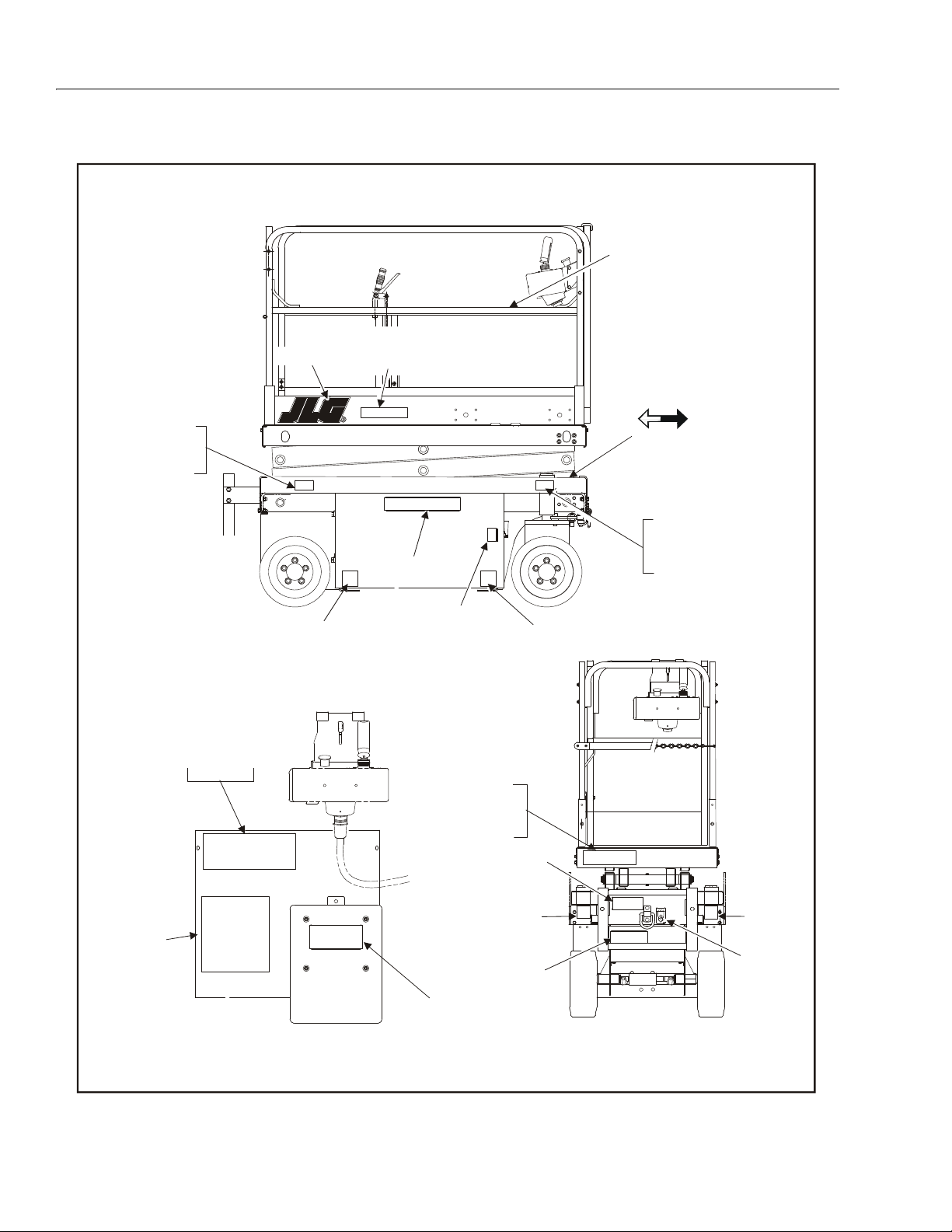
Figure 3-16. Decal Installation - 2033E3/2046E3/2646E3 & 2658E3 - Domestic/CSA (Sheet 1 of 2)
3-20 – JLG Sizzor – 3120761
Page 41

1703817
1703817
1703817
B
B
B
B
1703811
1703811
3251813
1703812
1703817
1703817
1703819
FWD
REV
1703818
1704133
2033E3
1704135
2046E3
1704136
1704137
2646E3
2658E3
2033E3
1704135
2046E3
1704136
1704137
2646E3
2658E3
1703823
1703813
3252584
2033E3
3252585
2046E3
3252586
3252587
2646E3
2658E3
1702773
1704277
1704133
1703694
3252591
2033E3/2046E3
2646E3/2658E3
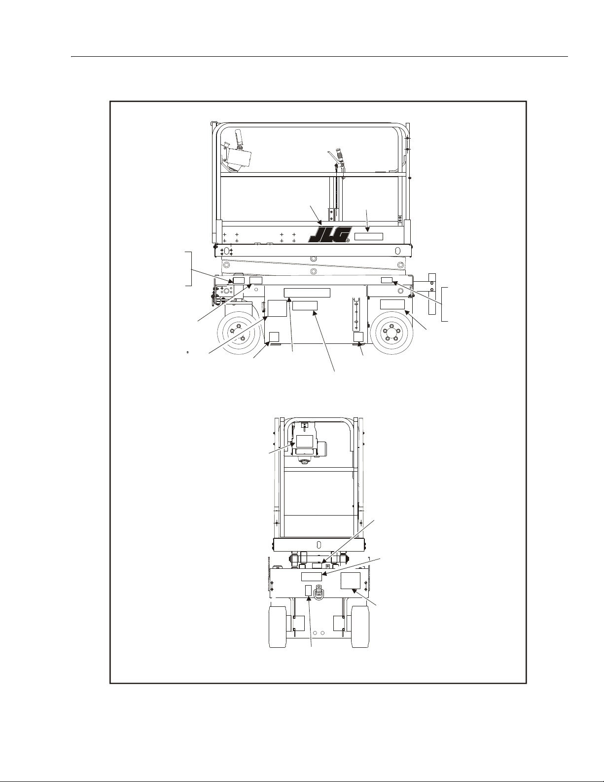
Figure 3-17. Decal Installation - 2033E3/2046E3/2646E3 & 2658E3 - Domestic/CSA (Sheet 2 of 2)
SECTION 3 - USER RESPONSIBILITIES AND MACHINE CONTROL
3120761 – JLG Sizzor – 3-21
Page 42

SECTION 3 - USER RESPONSIBILITIES AND MACHINE CONTROL
1703788
1703814
1703811
1703811
1704138
1704211
1703819
1703961
3252645
1703817
1703817
1703822
2033E3
2046E3/2646E3/2658E3
1704133
2033E3
1704135
2046E3
1704136
1704137
2646E3
2658E3
1704133
2033E3
1704135
2046E3
1704136
1704137
2646E3
2658E3
1703832
1703694
1703834
1703831
2033E3/2046E3
3252591
2646E3/2658E3
1703694
2033E3/2046E3
3252591
2646E3/2658E3
1703835
1703829
FWD
REV
3252584
2033E3
3252585
2046E3
3252586
3252587
2646E3
2658E3
1704277
1702773
1703833
Figure 3-18. Decal Installation - 2033E3/2046E3/2646E3 & 2658E3 - Brazil (Sheet 1 of 2)
3-22 – JLG Sizzor – 3120761
Page 43
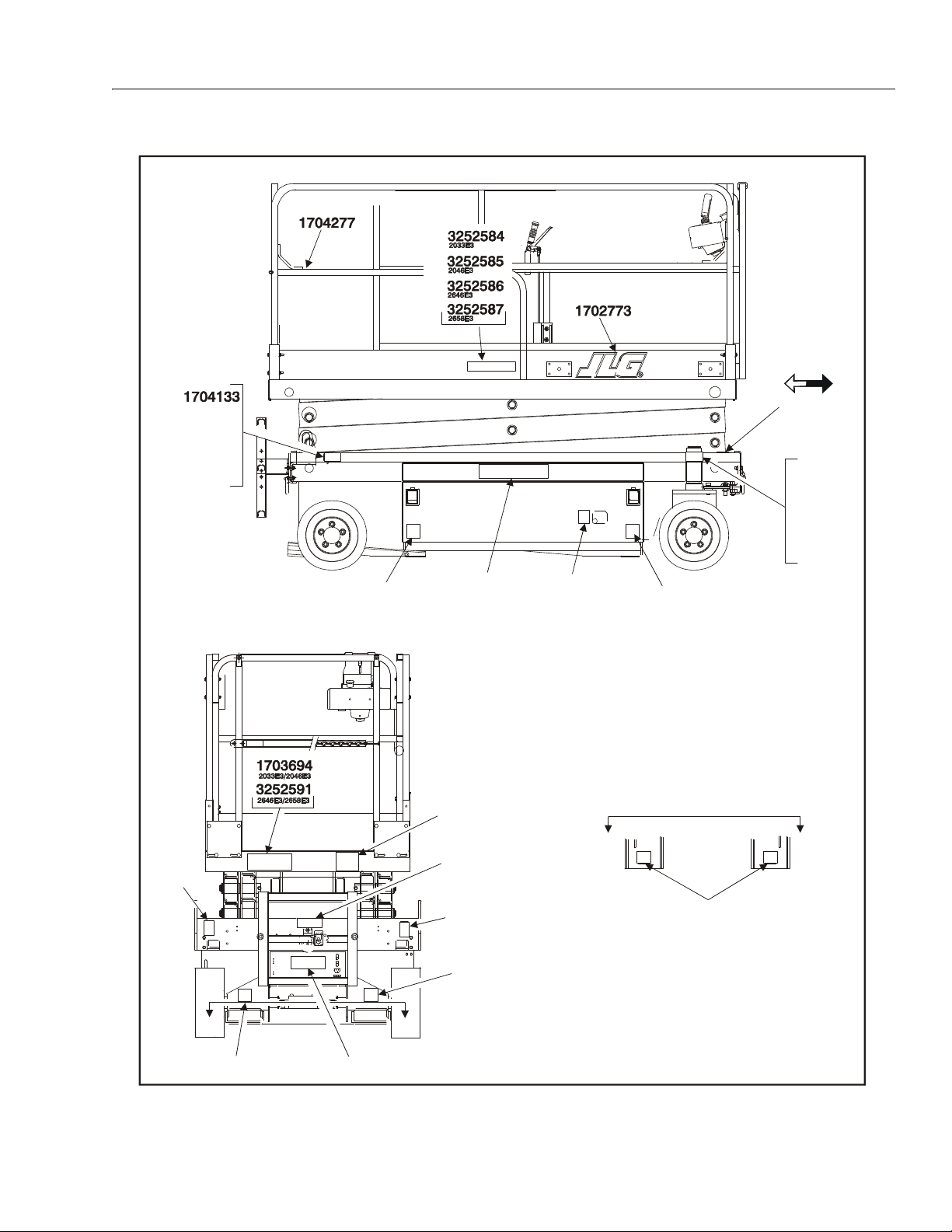
SECTION 3 - USER RESPONSIBILITIES AND MACHINE CONTROL
1703817
1703817
1703817
B
B
B
B
1703811
1703811
3251813
1703812
1703817
1703817
1703819
FWD
REV
1703833
1704133
2033E3
1704135
2046E3
1704136
1704137
2646E3
2658E3
2033E3
1704135
2046E3
1704136
1704137
2646E3
2658E3
1703834
1703832
Figure 3-19. Decal Installation - 2033E3/2046E3/2646E3 & 2658E3 - Brazil (Sheet 2 of 2)
3120761 – JLG Sizzor – 3-23
Page 44

SECTION 3 - USER RESPONSIBILITIES AND MACHINE CONTROL
1703788
1703814
1703811
1703811
1704138
1704211
1703819
1702552
3252645
1703817
1703817
1703822
2033E3
2046E3/2646E3/2658E3
1704133
2033E3
1704135
2046E3
1704136
1704137
2646E3
2658E3
1704133
2033E3
1704135
2046E3
1704136
1704137
2646E3
2658E3
1703840
1703694
1703842
1703839
2033E3/2046E3
3252591
2646E3/2658E3
1703694
2033E3/2046E3
3252591
2646E3/2658E3
1703843
1703837
FWD
REV
3252584
2033E3
3252585
2046E3
3252586
3252587
2646E3
2658E3
1703841
1704277
1702773
1702631
Figure 3-20. Decal Installation - 2033E3/2046E3/2646E3 & 2658E3 - Latin (Sheet 1 of 2)
3-24 – JLG Sizzor – 3120761
Page 45

1703817
1703817
1703817
B
B
B
B
1703811
1703811
3251813
1703812
1703817
1703817
1703819
FWD
REV
1703841
1704133
2033E3
1704135
2046E3
1704136
1704137
2646E3
2658E3
2033E3
1704135
2046E3
1704136
1704137
2646E3
2658E3
1703842
1703840
3252584
2033E3
3252585
2046E3
3252586
3252587
2646E3
2658E3
1702773
1704277
1704133
1703694
3252591
2033E3/2046E3
2646E3/2658E3
Figure 3-21. Decal Installation - 2033E3/2046E3/2646E3 & 2658E3 - Latin (Sheet 2 of 2)
SECTION 3 - USER RESPONSIBILITIES AND MACHINE CONTROL
3120761 – JLG Sizzor – 3-25
Page 46
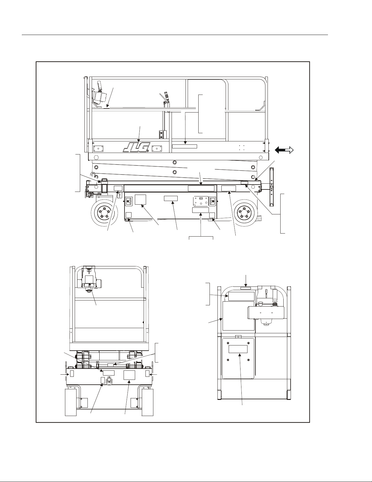
SECTION 3 - USER RESPONSIBILITIES AND MACHINE CONTROL
1703788
1703814
1703811
1703811
1704138
1704211
1703819
1704607
3252699
1703817
1703817
1703822
2033E3
2046E3/2646E3/2658E3
1704133
2033E3
1704135
2046E3
1704136
1704137
2646E3
2658E3
1704133
2033E3
1704135
2046E3
1704136
1704137
2646E3
2658E3
1704613
1703694
1704609
1704614
2033E3/2046E3
3252591
2646E3/2658E3
1703694
2033E3/2046E3
3252591
2646E3/2658E3
1704616
1704610
FWD
REV
3252584
2033E3
3252585
2046E3
3252586
3252587
2646E3
2658E3
1704611
1704277
1702773
1702631
Figure 3-22. Decal Installation - 2033E3/2046E3/2646E3 & 2658E3 - China (Sheet 1 of 2)
3-26 – JLG Sizzor – 3120761
Page 47
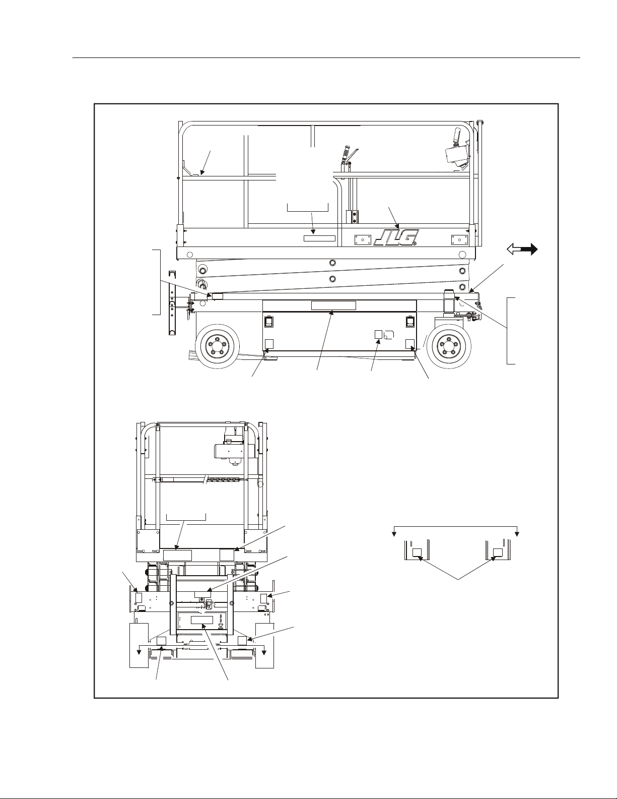
1703817
1703817
1703817
B
B
B
B
1703811
1703811
3251813
1703812
1703817
1703817
1703819
FWD
REV
1704611
1704133
2033E3
1704135
2046E3
1704136
1704137
2646E3
2658E3
2033E3
1704135
2046E3
1704136
1704137
2646E3
2658E3
1704609
1704613
3252584
2033E3
3252585
2046E3
3252586
3252587
2646E3
2658E3
1702773
1704277
1704133
1703694
3252591
2033E3/2046E3
2646E3/2658E3
Figure 3-23. Decal Installation - 2033E3/2046E3/2646E3 & 2658E3 - China (Sheet 2 of 2)
SECTION 3 - USER RESPONSIBILITIES AND MACHINE CONTROL
3120761 – JLG Sizzor – 3-27
Page 48

SECTION 3 - USER RESPONSIBILITIES AND MACHINE CONTROL
1703788
1703814
1703811
1703811
1704138
1704211
1703819
1703962
3252645
1703817
1703817
1703822
2033E3
2046E3/2646E3/2658E3
1704133
2033E3
1704135
2046E3
1704136
1704137
2646E3
2658E3
1704133
2033E3
1704135
2046E3
1704136
1704137
2646E3
2658E3
1703856
1703694
1703858
1703855
2033E3/2046E3
3252591
2646E3/2658E3
1703694
2033E3/2046E3
3252591
2646E3/2658E3
1703859
1703853
FWD
REV
3252584
2033E3
3252585
2046E3
3252586
3252587
2646E3
2658E3
1703857
1704277
1702773
1702631
Figure 3-24. Decal Installation - 2033E3/2046E3/2646E3 & 2658E3 - Korea (Sheet 1 of 2)
3-28 – JLG Sizzor – 3120761
Page 49
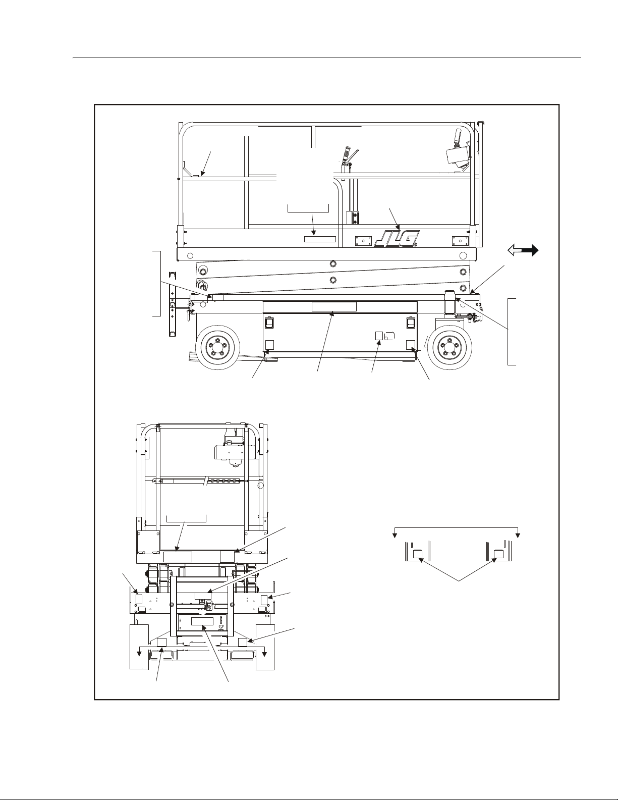
1703817
1703817
1703817
B
B
B
B
1703811
1703811
3251813
1703812
1703817
1703817
1703819
FWD
REV
1703857
1704133
2033E3
1704135
2046E3
1704136
1704137
2646E3
2658E3
2033E3
1704135
2046E3
1704136
1704137
2646E3
2658E3
1703858
1703856
3252584
2033E3
3252585
2046E3
3252586
3252587
2646E3
2658E3
1702773
1704277
1704133
1703694
3252591
2033E3/2046E3
2646E3/2658E3
Figure 3-25. Decal Installation - 2033E3/2046E3/2646E3 & 2658E3 - Korea (Sheet 2 of 2)
SECTION 3 - USER RESPONSIBILITIES AND MACHINE CONTROL
3120761 – JLG Sizzor – 3-29
Page 50

SECTION 3 - USER RESPONSIBILITIES AND MACHINE CONTROL
1703788
1703814
1703811
1703811
1704138
1704211
1703819
1701621
3252749
1703817
1703817
1703822
2033E3
2046E3/2646E3/2658E3
1704133
2033E3
1704135
2046E3
1704136
1704137
2646E3
2658E3
1704133
2033E3
1704135
2046E3
1704136
1704137
2646E3
2658E3
1703848
1703694
1703850
1704281
2033E3/2046E3
3252591
2646E3/2658E3
1703694
2033E3/2046E3
3252591
2646E3/2658E3
1704807
1703845
FWD
REV
3252584
2033E3
3252585
2046E3
3252586
3252587
2646E3
2658E3
1704282
1704277
1702773
1702631
Figure 3-26. Decal Installation - 2033E3/2046E3/2646E3 & 2658E3 - Japan (Sheet 1 of 2)
3-30 – JLG Sizzor – 3120761
Page 51

1703817
1703817
1703817
B
B
B
B
1703811
1703811
3251813
1703812
1703817
1703817
1703819
FWD
REV
1704282
1704133
2033E3
1704135
2046E3
1704136
1704137
2646E3
2658E3
2033E3
1704135
2046E3
1704136
1704137
2646E3
2658E3
1703850
1703848
3252584
2033E3
3252585
2046E3
3252586
3252587
2646E3
2658E3
1702773
1704277
1704133
1703694
3252591
2033E3/2046E3
2646E3/2658E3
Figure 3-27. Decal Installation - 2033E3/2046E3/2646E3 & 2658E3 - Japan (Sheet 2 of 2)
SECTION 3 - USER RESPONSIBILITIES AND MACHINE CONTROL
3120761 – JLG Sizzor – 3-31
Page 52

SECTION 3 - USER RESPONSIBILITIES AND MACHINE CONTROL
This page left blank intentionally.
3-32 – JLG Sizzor – 3120761
Page 53

SECTION 4 - MACHINE OPERATION
SECTION 4. MACHINE OPERATION
4.1 DESCRIPTION
This machine is a self-propelled aerial work platform on
top of an elevating scissor mechanism. The Scissor Lifts
intended purpose is to position personnel with their tools
and supplies at positions above ground level. The
machine can be used to reach work areas located above
machinery or equipment positioned at ground level.
The JLG Scissor Lift has a primary operator Control Station in the platform. From this Control Station, the operator
can drive and steer the machine in both forward and
reverse directions, raise and lower the platform and, if
equipped, operate the powered deck extension. The
machine has a Ground Control Station which will override
the Platform Control Station. Ground Controls operate lift
up and down and the powered deck extension (if
equipped). Ground Controls are to be used only in an
emergency to lower the platform to the ground or retract
the platform extension should the operator in the platform
be unable to do so.
Instructions and hazard warnings are posted adjacent to
both operator control stations and at other places on the
machine. It is extremely important that operators know
what instructions and warnings are placed on the
machine, and review these periodically so that they are
fresh in their minds. Vibrations emitted by these machines
are not hazardous to an operator in the work platform.
The JLG Scissor Lift is designed to provide efficient and
safe operation when maintained and operated in accordance with warnings on the machine, the Operating and
Safety Manual, the Service and Maintenance Manual and
all jobsite and government rules and regulations. As with
any type of machinery, the operator is very important to
efficient and safe operation. Owner/User/Operator must
be familiar with section 6, 7, 8, of ANSI A92.6-1999. It is
absolutely necessary that the JLG Lift be regularly maintained in accordance with this manual and the machine
Service and Maintenance Manual, and that any evidence
of lack of maintenance, malfunction, excessive wear, damage or modification to the machine be reported immediately to the machine owner or the jobsite supervisor or
safety manager and that the machine be taken out of service until all discrepancies are corrected.
The JLG Scissor Lift is not intended to be used to lift material other than supplies which personnel in the platform
require to do their job. Supplies or tools which extend outside the platform are prohibited. It must not be used as a
forklift, crane, support for overhead structure, or to push
or pull another object.
The JLG Scissor Lift is powered using hydraulic motors
and cylinders for the various machine motions. The
hydraulic components are controlled by electrically acti-
vated hydraulic valves using switches and control levers.
The speeds of functions controlled by control levers are
variable from zero to maximum speed, depending upon
the position of the control lever. Functions controlled by
toggle or push-button switches are either on or off. In
some instances, a function switch can be used in conjunction with the joystick to give the machine a higher function
speed range.
The JLG Scissor Lift is a two wheel drive machine with
drive power being supplied by a hydraulic motor for each
drive wheel. The rear wheels are supplied with spring
applied, hydraulically released brakes. These brakes are
automatically applied any time the drive joystick is
returned to the neutral position.
The platform capacity of each scissor lift model is as follows:
1532E3 - 600 lb. (270 kg)
1932E3 - 500 lb. (230 kg)
2033E3 and 2646E3
Standard - 750 lb. (340 kg)
Optional - 1,000 lb. (455 kg)
2046E3 and 2658E3 - 1,000 lb. (455 kg)
The weight in the platform should be uniformly distributed
in the center of the platform. The total combined weight of
personnel, tools and supplies must not exceed the above
figures.
Operators should refer to the specific capacity of the individual scissor lift indicated on the warning decals, paying
particular attention to any wind related restrictions which
may apply.
The platform may be raised only when positioned on firm,
level and uniform surfaces.
4.2 GENERAL
This section provides the necessary information needed
to operate the machine. Included in this section are the
procedures for starting, stopping, traveling, steering, parking, platform loading and transporting the machine. It is
important that the user read and understand the proper
procedures before operating the machine.
4.3 MOTOR OPERATION
Power Selector Switch
The Power Selector switch functions to direct battery
power to the desired control station. With the switch in the
3120761 – JLG Sizzor – 4-1
Page 54
SECTION 4 - MACHINE OPERATION
IMPORTANT
IMPORTANT
ground position, battery power is supplied to the emergency stop switch at the ground control station. When the
switch is in the platform position, battery power is supplied to the emergency stop switch at the platform control
station. The Power Selector Switch should be in the off
position when recharging the batteries and/or parking the
machine overnight.
Emergency Stop Switch
This switch, when in the on (out) position, provides battery
power to the ground controls or platform controls, as
applicable. In addition, the switch can be used to turn off
power (push the switch in) to the function controls in the
event of an emergency. If the machine shuts down due to
a trouble fault, turning the Emergency Stop Switch off and
then on again will reset the JLG SMART™ system.
Motor Activation
With the power selector switch in the appropriate position
(platform or ground) and the applicable emergency stop
switch in the on position and a function switch or controller is operated and held, the motor becomes activated
and operates the desired function. When operating the
platform controls, the applicable function switch must be
pressed before activating the controller to operate the
function.
IF A MOTOR MALFUNCTION NECESSITATES AN UNSCHEDULED
SHUTDOWN, DETERMINE AND CORRECT THE CAUSE BEFORE
RESUMING ANY OPERATION.
NOTE: Units equipped with optional tilt cutout, verify that
drive and lift functions are cutout when the platform
is elevated and the tilt alarm is activated.
Raising
1. If the machine is shut down, place the power selector switch to the desired position (platform or
ground).
2. Position the applicable emergency stop switch to
the on position.
3. If operating from the ground controls, position the lift
switch to up and hold until the desired elevation is
achieved. If operating from the platform controls,
press the lift switch and move the controller (joystick) forward and hold until the desired elevation is
reached. The lift switch is part of the enable circuit,
which supplies power to the lift switch and the joystick for 3 seconds after the lift switch is pressed. If
the joystick is not activated within 3 seconds after
the lift switch is pressed, power is removed from the
switch and the joystick and the switch must be
pressed again before activating the joystick. When
the joystick is returned to the center off position, the
operator has 3 seconds to re-activate the joystick or
select another function before power is removed by
the enable circuit. Do not try to operate the drive, lift,
and powered deck extension functions simultaneously. If the drive, lift, and powered deck extension
functions are selected simultaneously, no function
will operate. If this occurs, pause, then press only
one of the function switches to activate the function.
Lowering
ALWAYS POSITION THE POWER SELECTOR AND EMERGENCY
STOP SWITCHES TO THE OFF POSITION WHEN THE MACHINE IS
NOT IN USE.
E3 SERIES SCISSOR LIFTS ARE EQUIPPED WITH A PQ CONTROLLER, WHICH FEATURES A TRIGGER SWITCH ON THE
FRONT OF THE JOYSTICK. THIS SWITCH MUST BE DEPRESSED
TO OPERATE THE JOYSTICK, SELECT DESIRED FUNCTION,
SQUEEZE THE TRIGGER, THEN POSITION THE JOYSTICK TO
FORWARD OR REVERSE, AS DESIRED.
4.4 RAISING AND LOWERING (LIFTING)
DO NOT RAISE THE PLATFORM EXCEPT ON A HARD, LEVEL
SURFACE FREE OF OBSTRUCTIONS AND HOLES.
4-2 – JLG Sizzor – 3120761
ENSURE THE SCISSOR ARM AREA IS FREE OF PERSONNEL
PRIOR TO LOWERING THE PLATFORM.
If operating from the ground controls, position the lift
switch to down and hold until the desired elevation is
achieved or until the platform is fully lowered. If operating
from the platform controls, press the lift switch and move
the joystick backward and hold until the desired elevation
is reached or until the platform is fully lowered. The lift
switch is part of the enable circuit, which supplies power
to the lift switch and the joystick for 3 seconds after the lift
switch is pressed. If the joystick is not activated within 3
seconds after the lift switch is pressed, power is removed
from the switch and the joystick and the switch must be
pressed again before activating the joystick. When the joystick is returned to the center off position, the operator has
3 seconds to re-activate the joystick or select another
function before power is removed by the enable circuit.
Do not try to operate the drive, lift, and powered deck
extension functions simultaneously. If the drive, lift, and
Page 55

SECTION 4 - MACHINE OPERATION
IMPORTANT
IMPORTANT
powered deck extension functions are selected simultaneously, no function will operate. If this occurs, pause, then
press only one of the function switches to activate the
function.
DO NOT LIFT DOWN WITHOUT COMPLETELY RETRACTING THE
PLATFORM EXTENSION.
4.5 PLATFORM EXTENSION
Manual Platform Extension
The machine is equipped with a mechanically extendible
deck, which adds 3 feet (0.9 meters) to the front of the
platform, giving the operator better access to worksites.
To extend the deck, squeeze the release lever on the handle on the right side of the platform to release the lock pin,
then use the handle and handrail to push the extendible
deck out. To retract the deck, squeeze the release lever to
release the lock pin and use the handle and handrail to
pull and retract the deck. Be sure the lock pin is locked in
place after the deck is retracted. Maximum capacity of the
deck extension is 250 lb. (113 kg) - 1 person.
IF THE MACHINE IS EQUIPPED WITH THE OPTIONAL PIPE
RACKS, THE PLATFORM EXTENSION MUST BE IN THE
RETRACTED POSITION WHEN THE PIPE RACKS ARE LOADED.
FAILURE TO RETRACT THE PLATFORM EXTENSION COULD
RESULT IN DAMAGE TO THE PLATFORM EXTENSION.
Powered Deck Extension (If Equipped Models 2033E3, 2046E3, 2646E3, and
2658E3)
The models listed above may be equipped with a hydraulically-powered extendible deck, which adds either 4 feet
(1.2 meters) or 6 feet (1.8 meters) to the front of the platform, giving the operator better access to worksites. if
operating from the ground controls, position the Powered
Deck Extension switch to extend or retract, as required,
and hold until the deck is either fully extended or fully
retracted. If operating from the platform controls, press
the Powered Deck Extension switch and move the joystick
forward and hold until the powered deck extension is fully
extended or move the joystick backward and hold until the
powered deck extension is fully retracted. The Powered
Deck Extension switch is part of the enable circuit, which
supplies power to the Powered Deck Extension switch
and the joystick for 3 seconds after the Powered Deck
Extension switch is pressed. If the joystick is not activated
within 3 seconds after the Powered Deck Extension switch
is pressed, power is removed from the switch and joystick
and the switch must be pressed again before activating
the joystick. When the joystick is returned to the center off
position, the operator has 3 seconds to re-activate the joystick or select another function before power is removed
by the enable circuit. Do not try to operate the drive, lift,
and Powered Deck Extension functions simultaneously. If
the drive, lift, and Powered Deck Extension functions are
selected simultaneously, no function will operate. If this
occurs, pause, then press only one of the function
switches to activate the function. Maximum capacity of the
4 ft. (1.2 m) powered deck extension is 750 lb. (340 kg) - 2
persons. Maximum capacity of the 6 ft. (1.8 m) powered
deck extension is 350 lb. (159 kg) - 2 person.
IF THE MACHINE IS EQUIPPED WITH A POWERED DECK EXTENSION AND THE OPTIONAL FOLD-DOWN RAILS, THE RAILS MUST
BE IN THE UPRIGHT POSITION BEFORE RETRACTING THE
POWER DECK EXTENSION
4.6 STEERING
To steer the machine, the thumb operated steer control
switch on the controller handle is positioned to the right
for traveling right, or to the left for traveling left. When
released, the switch will return to the center-off position
and the wheels will remain in the previously selected position. To return the wheels to the straightened position, the
switch must be activated in the opposite direction until the
wheels are centered.
4.7 TRAVELING (DRIVING)
NOTE: Units equipped with optional tilt cutout, verify that
drive and lift functions are cutout when the platform
is elevated and the tilt alarm is activated.
DO NOT DRIVE WITH PLATFORM RAISED EXCEPT ON A
SMOOTH, FIRM AND LEVEL SURFACE FREE OF OBSTRUCTIONS
AND HOLES.
TO AVOID LOSS OF TRAVEL CONTROL OR UPSET ON GRADES
AND SIDESLOPES, DO NOT DRIVE MACHINE ON GRADES OR
SIDESLOPES EXCEEDING THOSE SPECIFIED FOR THE
MACHINE.
TRAVEL GRADES IN LOW DRIVE SPEED ONLY. USE EXTREME
CAUTION WHEN DRIVING IN REVERSE AND AT ALL TIMES WHEN
DRIVING WITH PLATFORM ELEVATED AND ESPECIALLY WHEN
DRIVING WITH ANY PART OF MACHINE WITHIN 6 FEET (1.8
METERS) OF AN OBSTRUCTION.
SELECTION OF MULTIPLE FUNCTIONS WHEN TRAVELING UP A
GRADE CAN CAUSE AN OVERCURRENT SHUTDOWN TO OCCUR.
IF THIS SHOULD HAPPEN, LET THE CONTROL HANDLE RETURN
TO NEUTRAL, THEN PAUSE FOR 3-5 SECONDS TO ALLOW THE
3120761 – JLG Sizzor – 4-3
Page 56
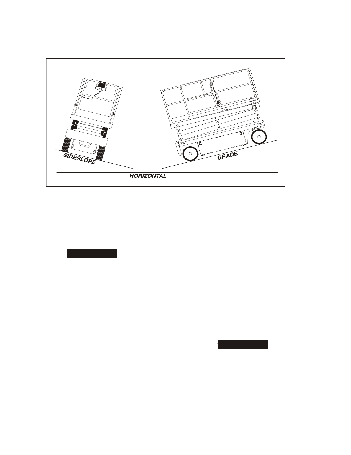
SECTION 4 - MACHINE OPERATION
IMPORTANT
IMPORTANT
Figure 4-1. Grade and Sideslope
SYSTEM TO RESET BEFORE RE-SELECTING A FUNCTION. TO
GO BACK DOWN THE GRADE, IF TRAVELING FORWARD UP THE
GRADE, BUMP THE CONTROL HANDLE FORWARD SLIGHTLY TO
ENSURE THE BRAKES ARE RELEASED BEFORE DESCENDING
THE GRADE.
WHEN TRAVELING A GRADE, MAXIMUM TRACTION IS OBTAINED
BY TRAVELING IN REVERSE. ALWAYS USE REVERSE TRAVEL
WITH LOW SPEED AND POSI-TRAC ENGAGED WHEN LOADING
ON A TRUCK OR WHEN ADEQUATE TRACTION IS NOT
OBTAINED TRAVELING FORWARD.
NOTE: The machine is equipped with a Pothole Protection
System which lowers automatically when the platform is raised. If the pothole protection does not fully
lower, the drive function is cut out until the platform is
completely lowered.
Traveling Forward
1. Place power selector switch at ground control station to platform.
2. Position emergency stop switch at Platform Control
Station to on position.
the joystick for 3 seconds after the drive switch is
pressed. If the joystick is not activated within 3 seconds after the drive switch is pressed, power is
removed from the switch and joystick and the switch
must be pressed again before activating the joystick.
When the joystick is returned to the center off position, the operator has 3 seconds to re-activate the
joystick or select another function before power is
removed by the enable circuit. For additional drive
speed, press the high drive speed switch simultaneously when depressing the drive switch or while
operating in the drive forward mode. The posi-trac
switch can also be used in conjunction with drive to
evenly divide the oil flow to each drive motor when
traction is a problem. Do not try to operate the drive,
lift, and powered deck extension functions simultaneously. If the drive, lift and powered deck extension
functions are selected simultaneously, no function
will operate. If this occurs, pause, then press only
one of the function switches to activate the function.
WHEN TRAVELING A GRADE, MAXIMUM TRACTION IS OBTAINED
BY TRAVELING IN REVERSE. REVERSE TRAVEL SHOULD BE
USED WHEN LOADING ON A TRUCK OR WHEN ADEQUATE
TRACTION IS NOT ACHIEVED BY TRAVELING FORWARD.
3. Press drive switch, in conjunction with the trigger
switch, and move joystick forward and hold for duration of travel. Drive speed is determined by the distance the joystick is moved from the center off
position. The drive switch is part of the enable circuit, which supplies power to the drive switch and
4-4 – JLG Sizzor – 3120761
NOTE: If the machine is equipped with the optional powered
deck extension, the DRIVE function is cut out when
the deck is extended with the platform raised above
the stowed position.
As an option, Models 2033E3 and 2646E3 may be
equipped for 1,000 lb. (455 kg) platform capacity.
Page 57

SECTION 4 - MACHINE OPERATION
When equipped for 1,000 lb. (455 kg) platform
capacity, Model 2033E3 cuts out the DRIVE function
at a platform height of 17 feet (5.2 m) and Model
2646E3 cuts out the DRIVE function at a platform
height of 19 feet (5.8 m).
Trav eli ng i n Rev ers e
1. Position power selector switch at ground control station to platform.
2. Position emergency stop switch at platform control
station to on position.
3. Press drive switch, in conjunction with the trigger
switch, and move joystick rearward (reverse) and
hold for duration of travel. Drive speed is determined
by the distance the joystick is moved from the center
off position. The drive switch is part of the enable circuit, which supplies power to the drive switch and
the joystick for 3 seconds after the drive switch is
pressed. If the joystick is not activated within 3 seconds after the drive switch is pressed, power is
removed from the switch and joystick and the switch
must be pressed again before activating the joystick.
When the joystick is returned to the center off position, the operator has 3 seconds to re-activate the
joystick or select another function before power is
removed by the enable circuit. DO NOT activate the
high drive speed switch when traveling in
reverse.
4.8 PARKING AND STOWING
4.9 PLATFORM LOADING
The platform maximum rated load capacity is shown on a
placard located on the platform and is based upon the following criteria.
1. Machine is positioned on a smooth, firm and level
surface.
2. All braking devices are engaged.
3. Maximum platform capacity for each model in its
standard configuration is as follows:
1532E3 - 600 lb. (270 kg)
1932E3 - 500 lb. (230 kg)
2033E3/2646E3 - 750 lb. (340 kg)
2046E3/2658E3 - 1,000 lb. (450 kg)
4. Optional platform capacity for Models 2033E3 and
20646E3 is 1,000 lb. (450 kg).
5. If machine is equipped with the optional pipe racks,
the maximum capacity of the pipe racks is 100 lb.
(45 kg). Maximum total capacity of the pipe racks
and platform combined is as follows:
2033E3/2646E3 - 650 lb. (295 kg)
2046E3/2658E3 - 900 lb. (408 kg)
6. Maximum capacity of the manual platform extension
is 250 lb. (120 kg) - 1 person.
7. For Models 2033E3, 2046E3, 2646E3, and 2658E3
only, maximum capacity of the optional 4 ft. (1.2 m)
powered deck extension is 750 lb. (340 kg) - 2 persons.
NOTE: When parking battery-powered units overnight, bat-
teries should be charged in accordance with instructions in Section 2 to ensure readiness for the
following workday.
Park and stow machine as follows:
1. Drive machine to a reasonably well-protected and
well-ventilated area.
2. Ensure platform is fully lowered.
3. Position emergency stop switch to off position.
4. If necessary, cover the instruction placards, caution
and warning decals so that they will be protected
from hostile environment.
5. Chock at least two wheels when parking machine for
an extended period of time.
6. Turn switch to OFF and remove key to disable
machine from unauthorized use.
8. For Models 2033E3, 2046E3, 2646E3, and 2658E3
only, maximum capacity of the optional 6 ft. (1.8 m)
powered deck extension is 250 lb. (120 kg) - 1 person.
NOTE: It is important to remember that the load should be
evenly distributed on the platform. The load should
be placed near the center of the platform when possible.
3120761 – JLG Sizzor – 4-5
Page 58
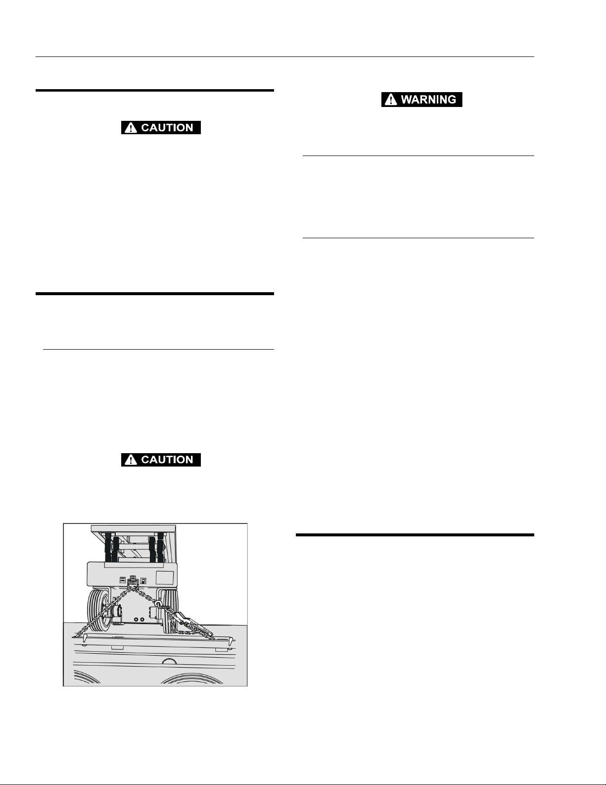
SECTION 4 - MACHINE OPERATION
Figure 4-2. E3 Tie Down
(front and rear typical)
4.10 SAFETY PROP
USE TIE DOWN EYES ONLY TO SECURE THE MACHINE FOR
SHIPPING. DO NOT USE TIE DOWN EYES TO LIFT THE MACHINE.
THE SAFETY PROP MUST BE USED WHENEVER MAINTENANCE
PERFORMED ON THE MACHINE REQUIRES THE SCISSOR ARMS
TO BE RAISED.
To engage the safety prop, raise the platform, then rotate
the prop clockwise until it hangs vertically. Lower the platform until the safety prop rests on the point provided on
the frame. Maintenance can now begin.
To store the safety prop, raise the platform so that the
prop can be rotated counterclockwise until it rests on the
stop provided on the scissor arms.
4.11 TRANSPORTING, TIE DOWN AND
LIFTING
Transporting (Loading/Unloading)
It is recommended the machine be winched when loading/unloading on a tilt/rollback type truck or trailer. Due to
a potential loss of traction, winch using the frame
mounted D-Rings. To winch be sure the machine brakes
are released.
Refer to the Emergency Towing Procedures in Section 6
or the Emergency Towing decal affixed to the machine.
Tie Down
When transporting the machine, the platform extension
must be fully retracted and the platform fully lowered in
the stowed mode with the machine securely tied down to
the truck or trailer deck. A D-ring is bolted to both the center front and center rear of the frame for tie-down
Lifting
If it becomes necessary to lift the machine, it is possible to
lift the machine with a forklift. On all models forklift pockets are provided at the rear of the machine.
In addition, all models can be lifted from either side with a
forklift, provided the forks are placed at the positions indicated by the decals on the machine. It is very important
that the forklift operator use only the designated lifting
areas to lift the machine.
NOTE: Machines may be equipped with optional bolt-on lift-
ing lugs, which are attached to the four corners of
the frame. These lugs enable the machine to be
lifted using cranes or other suitable lifting devices.
NOTE: If lifting becomes necessary, from the optional bolt
on lifting lugs, JLG Industries Inc. recommends the
use of a proper spreader bar to avoid damage to the
machine.
BE SURE THE MACHINE IS ON A LEVEL SURFACE OR PROPERLY SECURED BEFORE RELEASING THE BRAKES.
.
NOTE: Forklifts, cranes, or other lifting devices must be
capable of handling the following weights: 1532E3 2,630 lb. (1,193kg); 1932E3 - 2,900 lb. (1,315 kg);
2033E3 - 3,700 lb. (1,678 kg); 2046E3 - 3,940 lb.
(1,787 kg); 2646E3 - 4,370 lb. (1,982 kg); 2658E3 4,680 lb. (2,123 kg).
4.12 TOWING
It is not recommended that this machine be towed, except
in the event of an emergency such as a machine malfunction or a total machine power failure. Refer to Section 6 for
emergency towing procedures.
4-6 – JLG Sizzor – 3120761
Page 59

SECTION 4 - MACHINE OPERATION
Figure 4-3. Lifting Chart
3120761 – JLG Sizzor – 4-7
Page 60

SECTION 4 - MACHINE OPERATION
This page left blank intentionally.
4-8 – JLG Sizzor – 3120761
Page 61
SECTION 5 - EMERGENCY PROCEDURES
SECTION 5. EMERGENCY PROCEDURES
5.1 GENERAL
This section provides information on the procedures to be
followed and on the systems and controls to be used in
the event an emergency situation is encountered during
machine operation. Prior to operation of the machine and
periodically thereafter, the entire operating manual, including this section, should be reviewed by all personnel
whose responsibilities include any work or contact with
the machine.
5.2 EMERGENCY TOWING PROCEDURES
Although towing the machine is prohibited, provisions for
moving the machine, in case of a malfunction, power failure, or for loading on a truck, have been incorporated.
The following procedures are to be used ONLY for emergency movement to a suitable maintenance area or to
load the machine on a truck. These procedures are also
found on a decal affixed to the left front bumper of the
machine.
1. Chock the wheels securely.
2. Turn the black-handled valve knob on the main control valve counterclockwise all the way out to disengage the drive motors.
3. Using a 3/4 inch wrench, release the parking brake
by moving the brake cams to the horizontal position.
4. Using suitable equipment for assistance, remove the
chocks, and move the machine to an appropriate
maintenance area or onto the truck.
5.3 EMERGENCY CONTROLS AND THEIR
LOCATIONS
Emergency Stop Switch
These large red buttons, one located at the Ground Control Station and one at the Platform Control Station, will
immediately stop the machine when depressed.
CHECK MACHINE DAILY TO MAKE SURE EMERGENCY STOP
BUTTON IS IN PLACE AND THAT GROUND CONTROL INSTRUCTIONS ARE IN PLACE AND LEGIBLE.
Power Selector Switch
The key-operated Power Select switch, located at the
Ground Control Station, can also be used to shut down
the machine in an emergency situation. To shut off
machine power, turn the Power Select switch to the center
off (O) position.
Ground Control Station
The Ground Control Station is located on the left side of
the machine frame. The controls on this panel provide the
means for overriding the platform controls and for controlling the platform lift up and down functions from the
ground. Place the power select switch in the ground position and operate the lift switch to lift up or down.
Manual Descent
After moving the machine, complete the following procedures:
1. Position the machine on a firm, level surface.
2. Chock the wheels securely.
3. Using a 3/4 inch wrench, engage the parking brake
by moving the brake cams to the vertical position.
4. Turn the black-handled valve knob on the main control valve clockwise all the way in to engage the
drive motors.
5. Remove the chocks from the wheels.
The manual descent valve is used, in the event of total
power failure, to lower the platform using gravity. The
manual descent handle is located on the left front side of
the machine frame, just behind the left front wheel. The
handle is connected, by a stainless steel cable, to the
manual descent valve on the lift cylinder. Pulling the manual descent handle opens the valve spool, lowering the
platform.
3120761 – JLG Sizzor – 5-1
Page 62

SECTION 5 - EMERGENCY PROCEDURES
5.4 EMERGENCY OPERATION
KNOW HOW TO USE THE GROUND CONTROLS IN AN
EMERGENCY SITUATION.
Ground personnel must be thoroughly familiar with the
machine operating characteristics and the ground control
functions. Training should include operation of the
machine, review and understanding of this section and
hands-on operation of the controls in simulated emergencies.
Operator Unable to Control Machine
IF THE PLATFORM OPERATOR IS PINNED, TRAPPED OR
UNABLE TO OPERATE OR CONTROL THE MACHINE.
1. Operate the machine from ground controls ONLY
with the assistance of other personnel and equipment (cranes, overhead hoists, etc.) as may be
required to safely remove the danger or emergency
condition.
2. Other qualified personnel on the platform may use
the platform controls. DO NOT CONTINUE OPERATION IF CONTROLS DO NOT FUNCTION NORMALLY.
3. Cranes, forklift trucks or other equipment which may
be available are to be used to remove platform
occupants and stabilize motion of the machine in
case machine controls are inadequate or malfunction when used.
Righting of Tipped Machine
A forktruck of suitable capacity or equivalent equipment
should be placed under the elevated side of the chassis,
with a crane or other suitable lifting equipment used to lift
the platform while the chassis is lowered by the forklift or
other equipment.
Post-Incident Inspection
Following any accident, thoroughly inspect the machine
and test all functions first from the ground controls, then
from the platform controls. Do not lift above 10 feet until
you are certain that all damage has been repaired, if
required , and that all controls are operating correctly.
5.5 INCIDENT NOTIFICATION
It is imperative that JLG Industries, Inc. be notified immediately of any incident involving a JLG product. Even if no
injury or property damage is evident, the Product Safety
and Reliability Department at the factory should be contacted by telephone and provided with all necessary
details.
It should be noted that failure to notify the Manufacturer of
an incident involving a JLG Industries product within 48
hours of such an occurrence may void any warranty consideration on that particular machine.
Platform Caught Overhead
If the platform becomes jammed or snagged in overhead
structures or equipment, do not continue operation of the
machine from either the platform or the ground until the
operator and all personnel are safely moved to a secure
location. Only then should an attempt be made to free the
platform using any necessary equipment and personnel.
Do not operate controls to cause one or more wheels to
leave the ground.
5-2 – JLG Sizzor – 3120761
Page 63

SECTION 6 - INSPECTION AND REPAIR LOG
SECTION 6. INSPECTION AND REPAIR LOG
Table 6-1.Inspection and Repair Log
Date Comments
3120761 – JLG Sizzor – 6-1
Page 64

SECTION 6 - INSPECTION AND REPAIR LOG
Table 6-1.Inspection and Repair Log
Date Comments
6-2 – JLG Sizzor – 3120761
Page 65

CALIFORNIAN PROPOSITION 65
BATTERY WARNING
Battery posts,
terminals and related
accessories contain
lead and lead compounds,
chemical known to the
State of Califormia
to cause cancer and
reproductive harm.
WASH HANDS
AFTER HANDLING!
Page 66

JLG Worldwide Locations
3120761
Corporate Office
JLG Industries, Inc.
1 JLG Drive
McConnellsburg PA. 17233-9533
USA
(717) 485-5161
(717) 485-6417
JLG Industries (Australia)
P.O. Box 5119
11 Bolwarra Road
Port Macquarie
N.S.W. 2444
Australia
+61 2 65 811111
+61 2 65 810122
JLG Deutschland GmbH
Max-Planck-Str. 21
D - 27721 Ritterhude - Ihlpohl
Germany
+49 (0)421 69 350 20
+49 (0)421 69 350 45
Plataformas Elevadoras
JLG Iberica, S.L.
Trapadella, 2
P.I. Castellbisbal Sur
08755 Castellbisbal, Barcelona
Spain
+34 93 772 4700
+34 93 771 1762
JLG Latino Americana Ltda.
Rua Eng. Carlos Stevenson,
80-Suite 71
13092-310 Campinas-SP
Brazil
+55 19 3295 0407
+55 19 3295 1025
JLG Equipment Services Ltd.
Rm 1107 Landmark North
39 Lung Sum Avenue
Sheung Shui N. T.
Hong Kong
(852) 2639 5783
(852) 2639 5797
JLG Sverige AB
Enkopingsvagen 150
Box 704
SE - 176 27 Jarfalla
Sweden
+46 (0)850 659 500
+46 (0)850 659 534
www.jlg.com
JLG Industries (UK) Ltd
Bentley House
Bentley Avenue
Middleton
Greater Manchester
M24 2GP - England
+44 (0)161 654 1000
+44 (0)161 654 1001
JLG Industries (Italia) s.r.l.
Via Po. 22
20010 Pregnana Milanese - MI
Italy
+39 029 359 5210
+39 029 359 5845
JLG France SAS
Z.I. de Baulieu
47400 Fauillet
France
+33 (0)5 53 88 31 70
+33 (0)5 53 88 31 79
Oshkosh-JLG Singapore
Technology Equipment Pte Ltd.
29 Tuas Ave 4
Jurong Industrial Estate
639379 - Singapore
+65-6591-9030
+65-6591-9031
 Loading...