


Programat® P710
Operating Instructions


 1
1
2
Table of Contents
List of parts |
4 |
|
1. |
Introduction / Signs and Symbols |
7 |
1.1 |
Introduction |
|
1.2 |
Signs and symbols contained in these Operating Instructions |
|
1.3 |
Notes regarding the Operating Instructions |
|
1.4Note on the different voltage versions
1.5Notes on the images in the Operating Instructions
2. |
Safety First |
9 |
2.1 |
Indications |
|
2.2 |
Health and safety instructions |
|
3. |
Product Description |
14 |
3.1 |
General aspects |
|
3.2 |
Hazardous areas and safety equipment |
|
4. |
Installation and Initial Start-Up |
15 |
4.1Unpacking and checking the contents
4.2Selecting the location
4.3Removing the transport protection
4.4Removing the furnace head
4.5Initial start-up
5. Operation and Configuration |
22 |
5.1 Introduction to the operation
5.2 Firing programs and programming options
5.3Managing programs
5.4 Advanced functions of the furnace
5.5Multimedia functions
5.6Phone function
5.7Digital Shade Assistant (DSA) function
6. Practical Use |
69 |
6.1Firing with an Ivoclar Vivadent program
6.2Firing with an individual program
6.3Important notes on the use of the Infrared Technology
7. Maintenance, Cleaning and Diagnosis |
74 |
7.1 Monitoring and maintenance 7.2 Cleaning
7.3Service note
7.4Stand-by
7.5Power-saving mode
8. What If... |
76 |
8.1 Error messages
8.2 Additional error messages 8.3 Technical malfunctions
8.4Repairs
8.5Reset to factory settings
9. Product Specifications |
83 |
9.1Delivery form
9.2Technical data
9.3Acceptable operating conditions
9.4Acceptable transportation and storage conditions
10. Appendix |
85 |
10.1 Program table
3
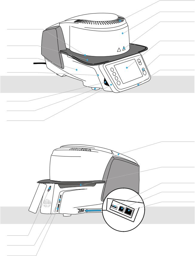
List of Parts
1Screw for cooling tray
2Cooling tray
3Housing base
4 Audio ports (in/out)
5Speaker
6Furnace feet 12b Progress display
13Operating unit fixature
14USB connections
15Card reader
7Air furnace head
8Furnace head housing
9Warnings
10Touch screen
11 Keypad
12a Optical Status Display (OSD)
16Cover for head opening mechanism
17Air vents (base)
18USB connection
19USB interface
20 Ethernet connection
4

21Insulation
22Firing plate
23Firing plate holder
24Frame plate
29On/Off switch
30Power socket
31Power cord
32Rating plate
33Vacuum pump fuse
34Vacuum pump socket
35Vacuum pump power cord
List of Parts
25QTK2 heating muffle
26Furnace head sealing ring
27Infrared camera
28Sealing surface
36Cover for head opening mechanism
37Connection cover
38Screw for connection cover
39Air vents rear panel
40Heating element fuse
41Vacuum hose connection
42 Vacuum hose
5

List of Parts
|
48 |
Plug lock |
|
49 |
Heater plug |
|
50 |
Heater plug socket |
|
51 |
Thermocouple plug |
|
52 |
Thermocouple plug |
43 |
Furnace head mounting |
socket |
|
||
|
53 |
Furnace head vacuum |
44 |
Furnace head |
connection |
|
release |
|
45Heater cable
46Thermocouple cable
47Furnace head vacuum hose
60 USB download cable |
61 Programat Firing Tray Kit 2 |
62 Programat USB stick |
63 Automatic Temperature |
|
|
|
Checking Set 2 ATK 2 (test |
|
|
|
set) |
|
|
64 Programat |
65 Programat |
WLAN stick |
Bluetooth flash drive |
6
1. Introduction / Signs and Symbols
1.1 Introduction
Dear Customer
Thank you for having purchased the Programat® P710. It is a state-of-the art furnace for dental applications. The furnace has been designed according to the latest industry standards. Inappropriate use may damage the equipment and be harmful to personnel. Please observe the relevant safety instructions and read the Operating Instructions carefully.
Enjoy working with the P710.
1.2 Signs and symbols contained in these Operating Instructions
The signs and symbols in these Operating Instructions facilitate the finding of important points and have the following meanings:
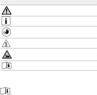
Symbol Note
Risks and dangers
Important information
Contraindication
Burn hazard
Risk of crushing
The Operating Instructions must be read.
1.3 Notes regarding the Operating Instructions
Furnace concerned: |
Programat P710 |
Target group: |
Dental technologists, dental professionals |
These Operating Instructions facilitate the correct, safe and economical use of the Programat P710 furnace. Should you lose the Operating Instructions, extra copies can be ordered at a nominal fee from your local Ivoclar Vivadent Service Centre or downloaded from www.ivoclarvivadent.com.
7

1. Introduction / Signs and Symbols
1.4Note on the different voltage versions
The furnace is available with different voltage versions:
–110 – 120 V / 50 – 60 Hz
–200 – 240 V / 50 – 60 Hz
In the Operating Instructions, the furnace is described in the 200-240 V voltage version. Please note that the voltage range shown on the images (e.g. rating plate) may differ depending on the voltage version of your furnace.
1.5 Notes on the images in the Operating Instructions
All images and illustrations in these Operating Instructions are used for exemplification and the details are not authoritative for the construction of the furnace. They are symbols, which may slightly differ from the original, e.g. due to simplification.
8
2. Safety First
This chapter is especially important for individuals who work with the Programat P710 or who have to carry out maintenance or repair work. This chapter must be read and the corresponding instructions followed!
2.1 Indications
The Programat P710 must only be used to fire dental ceramic materials and it should be used for this purpose only. Other uses than the ones stipulated, e.g. cooking of food, firing of other materials, etc., are contraindicated. The manufacturer does not assume any liability for damage resulting from misuse. The user is solely responsible for any risk resulting from failure to observe these Instructions.
Further instructions to assure proper use of the furnace:
–The instructions, regulations and notes in these Operating Instructions must be observed.
–The instructions, regulations and notes in the material's Instructions for Use must be observed.
–The furnace must be operated under the indicated environmental and operating conditions (see Chapter 9.3) The Programat P710 must be properly maintained.
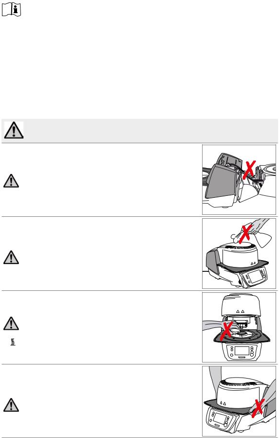
Risks and dangers
The furnace head should not be removed from the furnace base as long as the furnace head is connected by means of the cables.
Make sure that no liquids or other foreign substances enter the furnace.
Burn hazard: Never place objects in the firing chamber by hand, since there is a burn hazard. Always use the tongs (accessories) supplied for this purpose.  Never touch the hot surface of the furnace head, as there is a burn hazard.
Do not carry the furnace by the cooling tray.
9
2. Safety First
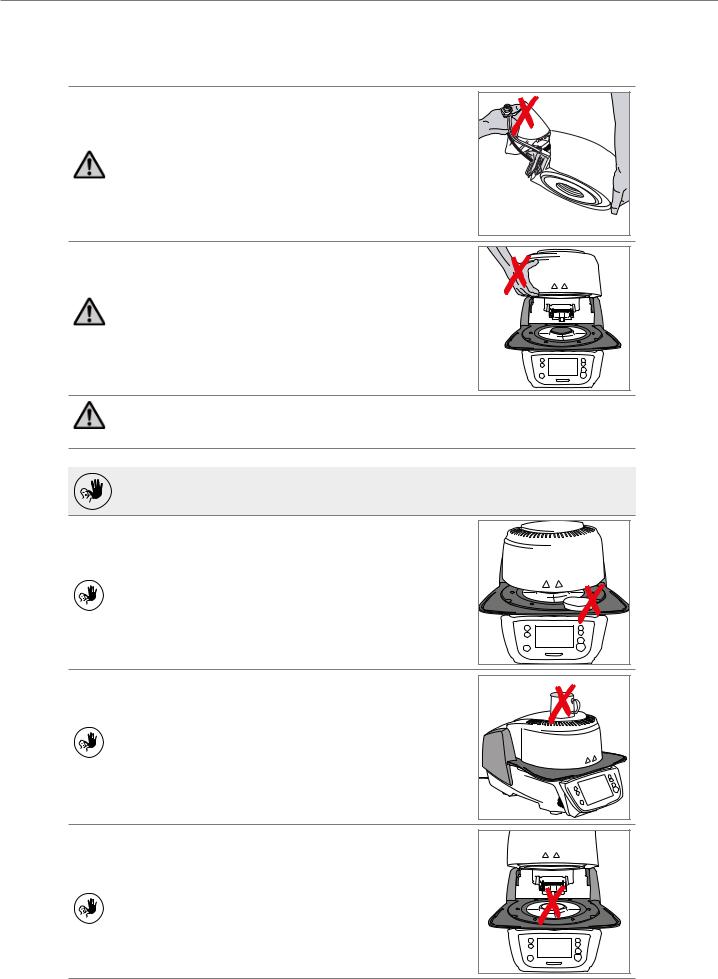
Do not carry the furnace head by the cables, since the cables and connections may be damaged.
The furnace head has an electric drive and must be operated by means of the electronic controls. Never open the furnace head by hand, since the mechanism will be damaged.
The furnace must not be operated if the quartz tube or the insulation in the firing chamber are damaged. There is a risk of electric shock upon contact with the heating wire. Avoid damage of the insulation by contact with the investment tongs or firing tongs.
Contraindication
Firing trays must not be placed in the area surrounding the firing table, since this will obstruct the closing of the furnace head.
Foreign objects must not be placed on the furnace head or the air vents. Make sure that no liquids or other foreign objects enter the air vents, since this may result in an electrical shock.
Never use the furnace without a firing table.
10
2. Safety First
Do not touch the thermocouple and the quartz tube in the firing chamber. Avoid contact with the skin (grease contamination), as the parts may be prematurely damaged.
Do not insert any foreign objects into the air vents. There is a risk of electrical shock.
This product contains ceramic fibres and may release fibre dust. Do not use compressed air, or blow on the furnace thus distributing the dust in the environment and observe the additional notes on page 13.
Risk of crushing / burn hazard
Never reach under the furnace head with the hand or other parts of the body, since there is a risk of crushing and a burn hazard.
Never reach inside the rear cover with the hand or particularly with the fingers . There is a risk of crushing.
11

2. Safety First
2.2Health and safety instructions
This furnace has been designed according to EN 61010-1 and has been shipped from the manufacturer in excellent condition as far as safety regulations are concerned. To maintain this condition and to ensure risk-free operation, the user must observe the notes and warnings contained in these Operating Instructions.
–The user must especially become familiar with the warnings and operating conditions to prevent injury to personnel or damage to materials. The manufacturer is not responsible for damage resulting from misuse or failure to observe the Operating Instructions. Warranty claims cannot be accepted in such cases.
–Before switching on the furnace, make sure that the voltage indicated on the rating plate complies with your local power supply.
–The mains socket must be equipped with a residual current operated device (RCD).
–The power plug acts as a circuit breaker and may only be connected with an easy-to-access power socket with protective contact.
–Use only the power cord originally supplied with the furnace. It must not be replaced by insufficiently rated ones.
–Place furnace on a fire-proof table. Observe local regulations (e.g. distance to combustible substances or objects, etc.).
–Always keep the air vents at the rear of the furnace free from obstruction.
–Do not touch any parts that become hot during operation of the furnace. Burn hazard!
–When removing hot components from the firing chamber (e.g. firing table, firing tray), make sure to place them on a fire-proof surface.
–Clean furnace only with a dry, soft cloth. Do not use any solvents! Disconnect power before cleaning and allow the furnace to cool down!
–The furnace must be cool before it is packed for transportation.
–Use original packaging for transportation purposes.
–Before calibration, maintenance, repair or change of parts, the power must be disconnected and the furnace has to be cool if it has to be opened.
–If calibration, maintenance or repair has to be carried out with the power connected and furnace open, only qualified personnel who are familiar with the risks and dangers may perform the procedures.
–After maintenance, the required safety tests (high voltage resistance, protective conductor, etc.) have to be carried out.
–Make sure that only fuses of the indicated type and rated current are used.
–If it is assumed that safe operation is no longer possible, the power must be disconnected to avoid accidental operation. Safe operation is no longer possible
–if the furnace is visibly damaged.
–if the furnace does not work.
–if the furnace has been stored under unfavourable conditions over an extended period of time.
–Use only original spare parts.
–The temperature range for faultless operation is +5°C to + 40°C.
–If the furnace has been stored at very low temperatures or high atmospheric humidity, the head has to be opened and the furnace dried or left to adjust to room temperature for approx. 4 hours (do not connect the power yet).
–The furnace is tested for use at altitudes of up to 2000 m above sea level.
–The furnace may only be used indoors.
–Before leaving the factory, the furnace functions were tested for several hours. It is therefore possible that these tests have caused slight discolouration of the insulation. Nevertheless, your Programat P710 is still a brand new furnace.
12
2. Safety First
Any disruption of the protective conductor either inside or outside the furnace or any loosening of the protective conductor may lead to danger for the user in case of malfunction. Deliberate interruptions are not tolerated.
Materials developing harmful gases must not be fired!
Warnings regarding the dismounting of the heating muffle
This product contains ceramic fibres and may release fibre dust. Fibre dust has proved to be carcinogenic in animal experiments. The heating muffle may only be dismounted by a qualified Ivoclar Vivadent After Sales Service Centre. Information regarding the Safety Data Sheet is also available from your Ivoclar Vivadent After Sales Service Centre.
Disposal:
The apparatus must not be disposed of in the normal domestic waste. Please correctly dispose of old furnaces according to the corresponding EU council directive. Information regarding disposal may also be found on the respective national Ivoclar Vivadent website.
13

3. Product Description
3.1 General issues
The Programat P710 is a modern ceramic furnace for dental applications. The firing chamber may be heated up to max. 1200 °C (2192 °F) by means of a heating element. Furthermore, the firing chamber has been designed in such a way that a vacuum may be created with a vacuum pump. Electronic components with the corresponding software monitor and control the firing programs. Additionally, the set and actual temperatures are continuously compared.
The Programat P710 consists of the following components:
–Furnace base with electronic controls
–Furnace head with firing chamber
–Cooling tray
–Firing table
–Power cord and hose for vacuum pump
3.2Hazardous areas and safety equipment
Description of the hazardous areas of the furnace: |
|
|
Hazardous area |
|
Type of risk |
|
||
|
|
|
Firing chamber |
|
Burn hazard |
|
|
|
Opening/closing mechanism |
|
Risk of crushing |
|
|
|
Electrical components |
|
Risk of electrical shock |
|
|
|
Description of the safety equipment of the furnace: |
|
|
Safety equipment |
|
Protective effect |
|
||
|
|
|
Protective conductor |
|
Protection from electrical shock |
|
|
|
Electrical fuses |
|
Protection from electrical shock |
|
|
|
Furnace housing and end caps |
|
Protection from electrical shock, burning and crushing |
|
|
|
14

4. Installation and Initial Start-Up
4.1Unpacking and checking the contents
Remove the furnace components from their packaging and place them on a suitable table. Please observe the instructions on the outer packaging.
There are no special transportation grips on the furnace. Support the bottom of the furnace to carry it. Check the delivery for completeness (see delivery form in Chapter 9) and transportation damage. If parts are damaged or missing, contact your Ivoclar Vivadent After Sales Service Centre.
We recommend keeping the original packaging for future service and transportation purposes.
4.2Selecting the location
Place the furnace on a flat table using the rubber feet. Make sure that the furnace is not placed in the immediate vicinity of heaters or other sources of heat. Make sure that air may properly circulate between the wall and the furnace. Also ensure that there is enough space between the furnace and the user, as the furnace releases heat during the opening of the furnace head.
The furnace should neither be placed nor operated in areas where there is an explosion hazard.
15
4. Installation and Initial Start-Up
4.3Assembly
Assembling the furnace is very easy and involves only few steps. Before you start assembling the furnace, make sure that the voltage indicated on the rating plate (32) complies with the local power supply. If this is not the case, the furnace must not be connected.
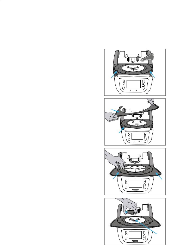
Step 1:
Assembling the cooling tray (2)
Remove the two fastening screws (1) for the cooling tray and the transport protection of the infrared camera.
Place the cooling tray (2) on the frame plate (24). Make sure that the cooling tray is correctly positioned on the frame plate.
Secure the cooling tray (2) with the two fastening screws (1).
Step 2:
Mounting the firing plate
Place the firing plate (22) on the firing plate holder (23). If placed correctly, the bottom of the firing plate is automatically centered in the firing plate holder.
1 |
1 |
2
|
24 |
1 |
2 |
22 

23
16

4. Installation and Initial Start-Up
Step 3:
Mounting the furnace head
The complete furnace head is best mounted with the rear panel of the furnace pointing towards the user. Lift the furnace head with both hands (see picture) and carefully position it on the furnace head mounting.
Position the furnace head mounting as shown in the picture until the furnace head audibly snaps into place. Make sure that the firing plate (5) is not damaged by mounting the furnace head.
Step 4: Connections
Connect the cables of the furnace head with the furnace base. Proceed as follows:
–Connect the vacuum hose (53)
–Insert the thermocouple plug (51) (make sure that the polarity of the plug is correct)
–Insert the heater plug (49)
1.Insert the heater plug in the intended socket.
2.Secure the heater plug by rotating it 45° until it snaps into place.
49 


51 |
53 |
2 |
|
1 |
|
17
4. Installation and Initial Start-Up
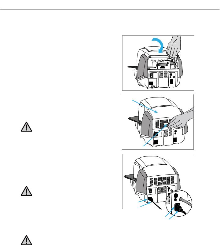
Step 5:
Hinging on the hood
Once all cables are properly connected to the furnace base, the hood (36) can be hinged over the connections until it snaps into place.
Step 6:
Mounting the connection cover
Mount the connection cover (37) and secure it with the fastening screw (38). When mounting the connection cover, make sure that the catch springs on the sides snap into place.
The furnace may only be operated with the hood and the connection cover mounted.
Step 7:
Establishing additional connections
Power connection
Please make sure that the voltage indicated on the rating plate complies with the local power supply. Subsequently, connect the power cord (31) with the power socket of the furnace (30).
The furnace may only be used with the supplied power cord!
Vacuum pump connection
Connect the vacuum pump plug (35) with the vacuum pump socket (34).
We recommend using a vacuum pump from Ivoclar Vivadent, since these pumps are especially coordinated with the furnace. If other pumps are used, please observe and do not exceed the maximum power consumption.
Do not shorten the vacuum hose! The minimum length of the vacuum hose is 1.6 m.
37 |
38 |
30 |
31 |
34 |
35 |
18

4. Installation and Initial Start-Up
4.4 Removing the furnace head
Before the hood and the connection cover are removed, the furnace has to be switched off and the power cord disconnected from the power socket.
1.Loosen and remove the knurled screw (38) of the connection cover (37).
2.Remove connection cover (37).
3.Open the hood (36).
4.Release the heater plug (49) and disconnect it with 45° anti-clockwise rotation.
5.Remove thermocouple plug (51).
6.Disconnect the vacuum hose (53).
7.Press the leaf spring (44) with a finger, lift off the furnace head at the same time and remove it.
Make sure the furnace head has completely cooled down before it is removed (fire hazard).
4.5 Initial start-up
1.Connect the power cord with the wall socket.
2.Put the On/Off switch (29) at the rear of the furnace on position I.
4.5.1 Basic settings upon initial start-up
Upon the initial start-up of the new furnace, a number of basic settings are required. These settings will be stored and will not appear anymore upon following starting procedures.
Step 1:
Language selection
The first setting is the language selection. The touch buttons (display keys) can be operated by tapping the display.
Step 1 |
|
Step 2 |
|
|
|
|
|
|
Step 3
Select the desired language using the [arrow up/down] buttons. Confirm the entry with the green button. By pressing the [Next] button, you will reach the next entry screen.
19
4. Installation and Initial Start-Up
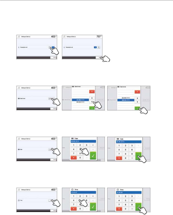
Step 2:
Select the temperature unit
Select the desired temperature unit.
By pressing the [Next] button, you will reach the next entry screen.
Step 3:
Select the date format
Select the date format.
Confirm the entry with the green button. By pressing the [Next] button, you will reach the next entry screen.
Step 4:
Enter the date
Set the date (day, month, year).
Confirm the entry with the green button. By pressing the [Next] button, you will reach the next entry screen.
Step 5:
Enter the time
Set the time (hours, minutes, seconds).
Confirm the entry with the green button. By pressing the [Next] button, you will reach the next entry screen.
The initial start-up and entry of the basic settings are now complete. The furnace will now automatically conduct a selftest. The performance of all furnace components is automatically checked.
20
4. Installation and Initial Start-Up
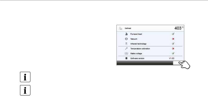
4.5.2 Start screen and self-test
Immediately after switching on, the display shows the start screen for a few seconds. Subsequently, the furnace conducts an automatic selftest. The performance of all furnace components is automatically checked.
The following functions are checked:
Function
|
|
Furnace head test in progress. |
|
|
|
Furnace head test |
The furnace head test was successful. |
|
|
|
|
|
|
The furnace head test failed. Please note the error message on the |
|
|
display. |
|
|
|
|
|
Vacuum test in progress. |
|
|
|
Vacuum test |
The vacuum test was successful. |
|
|
|
|
|
|
The vacuum test failed. Please note the error message on the display. |
|
|
|
|
|
IRT test in progress. |
|
|
|
IRT test |
The IRT test was successful. |
|
|
|
|
|
|
The IRT test failed. Please note the error message on the display. |
|
|
|
The following information is displayed: |
|
|
Information |
|
|
|
|
|
|
|
Temperature calibration of the furnace is not required. |
Temperature calibration |
|
|
|
Some time has passed since the last calibration. |
|
|
|
|
|
|
Please conduct a calibration procedure. |
|
|
|
|
|
The power supply voltage is in the acceptable range. |
Power supply |
|
|
|
The power supply is outside the acceptable range. |
|
|
|
|
|
|
|
Software version |
The currently installed software version is displayed. |
|
|
|
|
If the self-test was successful, the home screen is displayed.
If the program recognizes a malfunction during the test, a corresponding error message with the corresponding rectification information appears in the display.
The acoustic signal and the error message can be acknowledged with the corresponding buttons.
21
4. Installation and Initial Start-Up
Press the [Next] button to acknowledge the self-test.
Before the first firing, the firing chamber should be dehumidified using the dehumidification program (see Chapter 5.4 for details).
Please note that the furnace may require a certain acclimation time after having been set-up. This is particularly true if the furnace was exposed to substantial temperature changes (water condensation).
22
5. Operation and Configuration
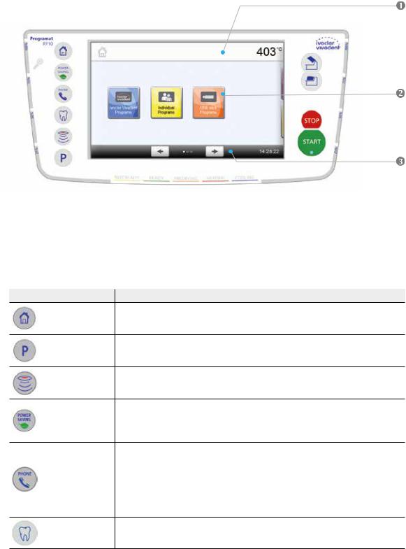
5.1 Introduction to the operation
5.1.1 Control unit
The Programat P710 is equipped with a widescreen colour display. The furnace can be intuitively operated by means of the membrane-sealed keypad and the touch screen. The touch buttons can be actuated by slightly tapping the display with the fingertip and the furnace runs the desired function.
The user interface in the display is divided into three sections:
1.Information bar (e.g. indication of the current furnace temperature, the selected program, etc.)
2.Main screen (e.g. editing firing programs, changing the settings, etc.)
3.Navigation bar (e.g. scrolling, scrolling in higher levels, calling up favourite programs, etc.)
5.1.2 Description of the key functions
Key |
Function |
Home
Switch to home screen (main menu)
Program key
Press once: Display of the currently selected program
Press twice: Switch to the program selection via numbers
IRT key
With this key, the infrared image of the object can be displayed during the closing process.
Power-saving key
Power-saving function activated (only possible with the furnace head closed and the furnace on idle). The display shows the power-saving icon. Pressing any key ends the power-saving function.
Phone key
–If the furnace is not yet connected to a mobile phone, pressing this key results in the Bluetooth settings being displayed.
–If the furnace is already connected to a mobile phone, pressing this key results in the mobile phone menu being displayed.
–During an active phone call, this key can be used to fade the mobile phone screen in or out.
Digital Shade Assistent key
The Digital Shade Assistant (DSA) can be started and ended with this key.
23
5. Operation and Configuration
Open furnace head
Quick cooling with the furnace head open:
If the furnace head is completely open and the OPEN FURNACE HEAD key is pressed again, the quick cooling function is activated. I.e. the vacuum pump is switched on for 5 minutes. This function can be stopped at any time by pressing STOP, CLOSE FURNACE HEAD or START. This function can be activated any time when the furnace head is open.
Close furnace head
STOP
A program in progress can be paused by pressing the STOP key and stopped by pressing
STOP twice. Movement of the furnace head can be stopped at any time by pressing
STOP. The beeper can be confirmed by pressing the STOP key.
START (Start LED)
Starts the selected program. The green LED indicates that a program is active. If the program is paused (1x STOP), the Start LED flashes until renewed pressing of START results in the program being resumed.
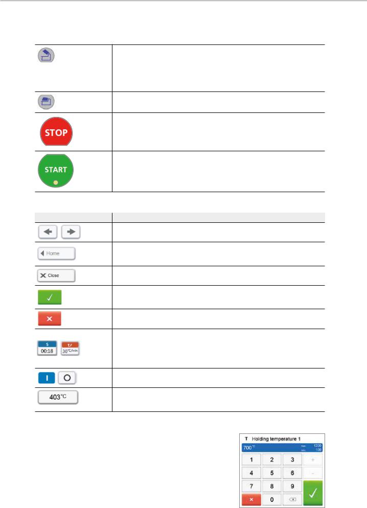
5.1.3 Description of the most important touch buttons
Button |
Function |
Scroll left / Scroll right
With these buttons, for example, you can scroll to page 2 of the home screen.
Back with note
With this button, you can change to the "next higher" menu level. The button indicates to which screen you change, e.g. to the home screen.
Close
With this button, you can close sub-menus.
Confirm your entries
This button is used to confirm an entry. If the button appears pale green, no entry has been made yet or the value entered is not in the acceptable range.
Cancel entry
The entry can be cancelled with this button; changed values are not saved.
Program parameter button
Pressing these buttons allows you to change program parameters. A selection list or numeric pad for entering the values appears.
The upper half of the button itself shows the parameter in question (e.g. closing time), while the lower half shows the entered value (e.g. 00:18).
On/Off button
This button is used to switch functions on or off.
Parameter button
Pressing these buttons results in a selection list or numeric pad for entering the values to appear.
5.1.4 Description of the numeric pad and selection list
–Numeric pad
The numeric pad enables the entering and changing of parameters, e.g. in firing programs or set-up menus. Additionally, the currently set value is indicated,
as well as the minimum and maximum values.
An entry must be confirmed with the green button. As soon as the entry has been confirmed, the numeric pad is closed. If the button appears pale green, the value entered is not within the acceptable range.
The numeric pad can be closed with the red button, without any parameters being changed.
24

5. Operation and Configuration
–Selection list
In the selection list, the desired parameter can be selected by using the up/down arrows. An entry must be confirmed with the green button. After that, the selection list is closed.
The selection list can be closed with the red button, without any parameters being changed.
5.1.5 Description of the home screen
After the furnace is switched on, the display shows the home screen. All functions of the Programat can be selected from this screen. With the HOME key, you can change to the home screen.
By pressing a selection button, you will reach the corresponding menu (e.g. firing programs, settings, calibration, etc.).
The next page of the home screen can be accessed with the arrow button, where additional functions are available.
The circles between the arrows indicate the number of pages. The current page is marked with a light dot.
5.1.6 Description of the speaker sounds
– Upon closing the furnace head below 100°C
There is a risk of crushing upon closing the furnace head. If the furnace head is closed below 100°C, the user is notified of this risk by an acoustic signal.
–After the self-test is completed
To inform the user that an automatic self-test has been successfully completed, a preset, non-changeable melody is played.
–Furnace head open and temperature below 560°C
To inform the user that the temperature in the open furnace head has dropped below 560°C, the selected melody is played (5 seconds). In other words, the furnace head is basically cool enough for the next program start. The signal transmitter can only be ended with the STOP key.
–Furnace head open and temperature below 360°C
To inform the user that the temperature in the open furnace head has dropped below 360°C, the selected melody is played. If the first playback (10 seconds) is not acknowledged with the STOP key, a second playback sounds after
5 minutes (for 5 minutes) to signal that the furnace head is cooling down. After that, no further signal is played.
If one of the two playbacks is acknowledged with the STOP key, the signal transmitter is switched off and no further signals will be sounded.
–For error messages
Error messages are acoustically supported with the "error melody" (endless beep). The signal transmitter may be switched off with the STOP key, while the error message still remains visible. If the error message is acknowledged with the corresponding button, the signal transmitter is also switched off.
25

5. Operation and Configuration
5.1.7 Optical status and progress display (OSD)
The Optical Status Display (OSD) (12) shows the most important statuses of the furnace. The following activities are indicated:
Shade |
Activity |
|
|
|
|
Yellow |
The furnace is performing the self-test or is not ready for use, as the recommended tem- |
|
perature range for a program start has not yet been reached. |
||
|
||
|
|
|
Yellow (flashing) |
Information, note or error message |
|
|
|
|
Green |
The furnace is ready for use; the currently selected program can be started. |
|
|
|
|
Orange |
Program is closing the furnace head or is in predrying mode |
|
|
|
|
Red |
Program is heating up or is in holding time mode |
|
|
|
|
Blue |
Program is in long-term cooling or is opening the furnace head |
|
|
|
Progress display:
During an active process, the progress of the program is also shown by the OSD. This is done by stage-to-stage lighting up of the lateral OSD (12b).
5.1.8 User code
For safety reasons, a user code is required for certain settings. The user code ex factory is as follows:
1234
The user code can be individually changed. See Chapter Settings 5.4 for details.
5.2 Firing programs and programming options
5.2.1 Program structure
The furnace offers several types of programs:
a.Programs for Ivoclar Vivadent materials
b.700 free, individually adjustable programs
b. 700 free, individually adjustable programs on a USB stick
The program types are subdivided into program groups. Each program group consists of 20 programs.
All programs are equivalent and therefore full-fledged programs. For each program, all the parameters can be adjusted.
a) Programs for Ivoclar Vivadent materials (See enclosed Program Table)
When the furnace is delivered ex works, the Ivoclar Vivadent programs already contain the recommended material parameter settings and are write-protected. Consequently, it is not possible to accidentally overwrite the programs.
However, the parameters can be changed and overwritten at any time, if required, if the programs are to be used for other purposes. Therefore, these programs are also available as individual programs.
In case of software updates, individually changed parameters in Ivoclar Vivadent programs might be reset to the factory settings or changed!
b) Free, individually adjustable programs
The programs are designed in such a way that they can be either used as conventional one-stage programs, as two-stage programs or, if required, as three-stage programs. The programs and program groups can be individually named.
In case of software updates, individually changed parameters in individual programs are NOT reset to the factory settings or changed!
26
5. Operation and Configuration
c) Free, individually adjustable programs on a USB stick
In a first step, a USB stick must be prepared as program memory (see Chapter 5.4). The programs are designed in such a way that the can be either used as conventional one-stage programs, as two-stage programs or, if required, as three-stage programs. The programs and program groups can be individually named.
In case of software updates, individually changed parameters in individual programs are NOT reset to the factory settings or changed!
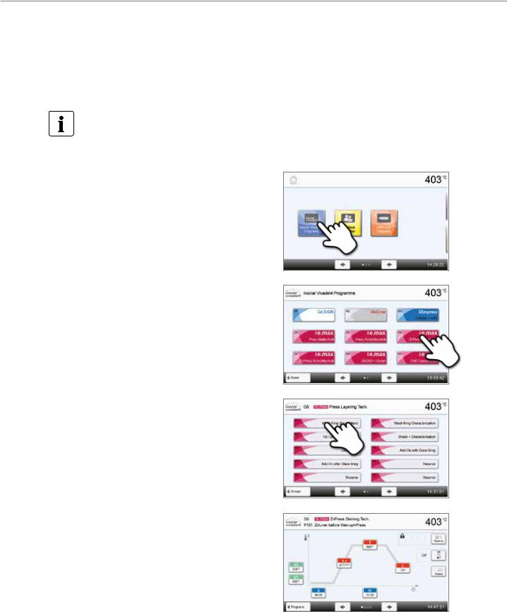
5.2.2 Program selection
The program selection requires only few steps:
1. Select program type
2. Select program group
3. Select the program
4. Start program or edit program parameters
The firing program can now be started or, as an alternative, the program parameters can be changed.
27
 Loading...