


 Ivomat IP3
Operating Instructions Bedienungsanleitung Mode d’emploi Istruzioni d’uso Instrucciones de uso Instruções de Uso

2

Ivomat IP3
Table of Contents
1.Introduction / Signs and Symbols
1.1Preface
1.2Introduction
1.3Signs and Symbols
2.Safety First
2.1Indications
2.2. Health and safety instructions
3.Product Description
3.1Components
3.2Functional description
3.3Hazardous areas and safety equipment
4.Installation
4.1Unpacking and checking the contents
4.2Selecting the location
4.3Connections
4.4Connecting the return water canister
5.Start-Up
5.1Switching on/off
5.2Filling in water
6.Operation
6.1Placing the objects and starting the program
6.2End of the program and removing the objects
7.Maintenance, Cleaning, and Diagnosis
7.1Monitoring and maintenance
7.2Cleaning
7.3Maintenance
8.What If …
8.1Power failure
8.2Repair
8.3Technical malfunctions
9.Product Specifications
9.1Delivery form
9.2Technical data
9.3Acceptable operating conditions
9.4Acceptable transportation conditions
English
3

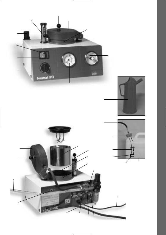
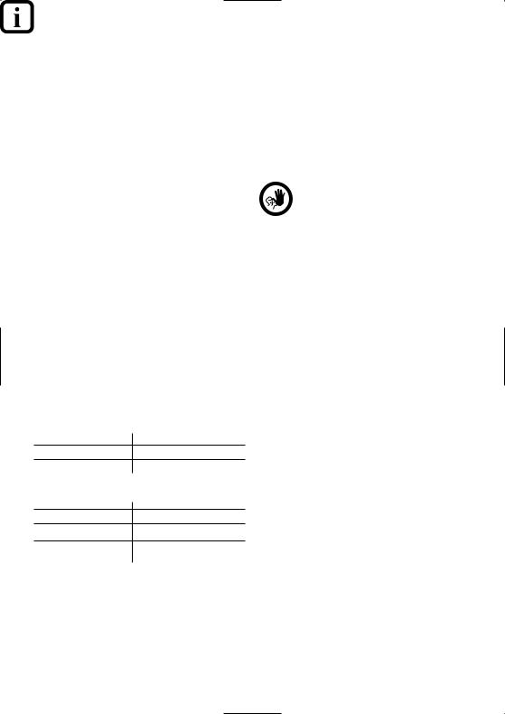
List of Parts
1)Air filter control 1a) Sight glass
1b) Release button
2)Safety lever
3)Bold knob
4)Pressure chamber lid
5)Pressure chamber
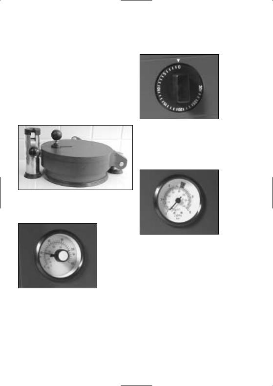
6)Thermostat
7)Manometer
8)Timer
9)Mains switch
10)Pilot lamp
11)Non-return valve
12)Compressed air hose
13)Power cord
14)Fuse cap
15)Fuse
16)Safety valve
17)Reset button
18)Water drain hose
19)Canister cap
20)Return water canister
21)Canister hose
22)Sealing washer for sound absorber
23)Sound absorber
24)Collar
25)Air hole
26)Collar screw
27)Polymerization container lid
28)Alligator clips
29)Polymerization container
30)Replenishing cup
4

3
2 |
4 |
|
5
1
10
9
8
7
 27
27
 28
28
29
4
3
12
17
18
14,15
6
30
|
18 |
|
|
19 |
|
2 |
21 |
|
5a |
22 |
|
|
|
|
5 |
23 |
20 |
|
11 |
|
 1
1
13
 1a
1a
 1b
1b
16 16a
English
5

1. Introduction / Signs and Symbols
1.1Preface
Dear Customer,
Thank you for having purchased the IVOMAT IP3. This apparatus is a technically advanced product. Please read these Operating Instructions carefully and use the IVOMAT IP3 according to the instructions. Should you have any further questions, please contact your dealer or Ivoclar Vivadent directly.
1.2Introduction
Apparatus: IVOMAT IP3
Target group: Dental professionals
The IVOMAT IP3 is suitable for the polymerization of dental resins. The Operating Instructions ensure safe, correct, and economic use of the IVOMAT IP3. They are divided into several, clearly structured chapters. This should enable you to locate specific topics quickly and easily.
To inform you about risks, dangers, important information, and contraindications, these Instructions contain corresponding signs/symbols to mark important paragraphs.
We recommend keeping the Instructions in a safe place near the apparatus to have immediate access to the information if necessary.
Should you lose the Operating Instructions, extra copies can be ordered at a normal fee from your local Ivoclar Vivadent Service Center.
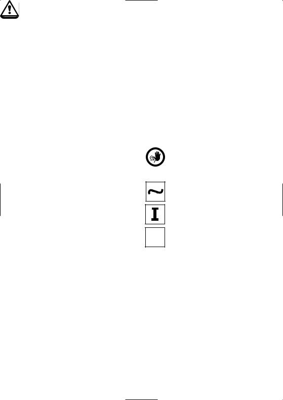
1.3 Signs and symbols
The signs and symbols in these Operating Instructions facilitate the finding of important points and have the following meanings:
In the Operating Instructions
Risks and dangers
Information
Contraindication
On the apparatus
Alternating current
On
O Off
6

2. Safety First
This chapter is especially important for individuals who work with the IVOMAT IP3 or who have to carry out maintenance or repair work. This chapter must be read and the corresponding instructions followed.
2.1 Indications
The IVOMAT IP3 has been especially developed for the polymerization of dental resins and materials and should be used for these purposes only.
Uses other than the ones stipulated are contraindicated. The manufacturer does not assume any liability for damage resulting from misuse. The user is solely responsible for any risk resulting from failure to observe these instructions.
Further instructions to assure proper use of the furnace:
–The instructions, regulations, and notes in these Operating Instructions must be observed.
–The apparatus must be operated under the indicated environmental and operating conditions
(see Chapter 9)
–The IVOMAT IP3 must be properly maintained.
2.2.1
Risks and dangers
Make sure that no liquids or other foreign objects enter the air vents, since this may result in an electrical shock.
2.2.2
Risks and dangers
The housing must not be opened while it is connected to the power supply, since there is a risk of electrical shock. The connection cover may only be opened by a qualified service center.
English
7

3. Product Description |
4. Installation |
3.1 Components
The IVOMAT IP3 consists of the following components:
–Apparatus with air filter control
–Non-return valve
–1.5 m compressed air hose
–1.2 m water drain hose with canister cap
–Canister hose with sound absorber; polymerization container in pressure chamber, and 3 object clips secured to removable lid
–1 return water container
–1 replenishing cup
Special accessories
–IVOMAT refill container type IN 1
–Wallfixator
3.2 Functional description
The pressure chamber is equipped with a heater.
In this way, the water can be heated to the temperature required for the corresponding material.
The pressure chamber is impinged with compressed air to achieve optimum homogeneity of the material. The polymerization time can be set by means of the timer.
3.3 Hazardous areas and safety equipment
Description of the hazardous areas:
Hazardous area |
|
Type of risk |
|
Safety holder |
|
Electrical shock |
|
Air vents |
|
Electrical shock |
|
Description of the safety equipment |
|||
Safety equipment |
|
Protective effect |
|
|
|||
Protective conductor |
|
Protection from electrical shock |
|
|
|
|
|
IP44 (system of protection) |
|
Protection from electrical shock |
|
|
|
|
|
Protective thermal switch |
|
Protects the IVOMAT IP3 |
|
|
|
from overheating |
|
4.1 Unpacking and checking the contents
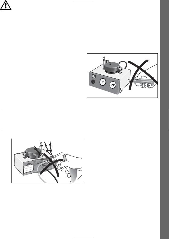
Remove the apparatus from its packaging and check for possible transportation damage. We recommend keeping the original packaging for future transportation purposes. Use only the original packaging for transportation.
Do not carry the IVOMAT IP3 by means of the power cord. Support the bottom of the IVOMAT IP3 with both hands to carry it.
4.2 Selecting the location
Place the apparatus on a flat table using the rubber feet. Make sure that the apparatus is not placed in the immediate vicinity of heaters or other sources of heat. Furthermore, protect the apparatus from direct sunlight.
4.3 Connections
Make sure the voltage indicated on the rating plate complies with the local power supply. If this is not the case, the apparatus must not be connected.
Connecting the compressed air hose
Make sure that the hose is properly connected.
Power connection
Make sure that the power cord does not touch any parts of the apparatus that become hot during use.
The electrical installations of the room where the apparatus is located must comply with the national regulations and IEC standards.
8

4.4 Connecting the return water canister
–Fill return water canister (20) to a depth of 3–5 cm.
–Insert the canister hose into the canister and screw cap on (19).
–Put the canister on the floor in a suitable place.
–Lift the safety lever (2) and engage. Push the bolt to the right using the knob (3) and lift the lid (4) of the vessel.
–Remove protective insert used during transportation.
5. Start-up
5.1 Switching on / off
Take the polymerization container (29) with lid (27) out of the pressure chamber. Switch on main (9) (0 to I). The pilot lamp (10) will light up when the apparatus is ready for use.
The apparatus may be kept ready for use throughout the day (mains switch on I), but the pressure chamber lid (4) should remain either unbolted or open after each use.
5.2 Filling in water
Fill the pressure chamber with water.
–Maximum filling height: up to the market groove in the chamber
–Minimum filling height: objects to be polymerized must be completely under water
English
9
6. Operation
6.1 Placing the objects and starting the program
–Remove the lid (27) from the polymerization contains. Secure the objects to be polymerized on the alligator clips (28).
–Slowly insert the polymerization container with lid and objects, or models held by the Wallfixator, into the pressure chamber.
–Close chamber lid (4). Bolt the chamber by sliding the knob (3) to the left. Press safety lever down until it audibly clicks into place.
Timer
– Automatic program:
• The manometer (7) indicates the rise in pressure (check to make sure that the required operating pressure has been reached by the time the selected temperature has been achieved.
Chamber lid
–Set polymerization thermostat (6). Move the red indicator to the desired temperature.
Thermostat (°C)
The program automatically begins, once the timer is set. Note: For times under 5 minutes, first turn the timer to approximately 10 minutes, then immediately turn it back to the desired time.
(If required, the time may be returned to zero during the automatic program in progress. The time may also be prolonged or shortened.)
Manometer
•The water in the pressure chamber is heated.
The black indicator on the thermostat registers the current temperature.
•Once the desired temperature is reached, the set polymerization time begins (timer countdown).
•After the polymerization time, the water is ejected from the pressure chamber and flows into the canister. At the same time, the pressure is released (indicated on the manometer).
10
6.2End of the program and removing the objects
–Opening the pressure chamber lid:
Do not lift the safety lever before the manometer needle is at zero and the black thermostat indicator has fallen below 110 °C (230 °F). (Any residual pressure is blown off against the chamber lid.) The lid can then be safely unbolted by pushing the knob to the right and the chamber lid opened.
–Removing the polymerized objects: Remove the polymerization container including the lid from the pressure chamber and allow it to cool for a few minutes before removing the polymerized objects. Cooling too quickly may result in stress within the resin materials.
–Use softened water (not distilled) or water 4–9° hard (70–160 ppm/°
US = 5-12° Brit.) (Ph 7–8/20 °C).
If tape water of more than 9° hard (16° Fr) is used, special care must be given to maintenance and cleaning or decalcification (see decalcification,
page 11).
–Make sure that no wax enters the pressure chamber.
–Set the polymerization time only after bolting the pressure chamber lid.
–Caution: Do not touch hot parts of the apparatus during use.
7.Maintenance, Cleaning, and Diagnosis
For safety reasons, disconnect power cord for all cleaning and maintenance procedures.
7.1 Monitoring and maintenance
Keep pressure chamber sealing rim (5a) and sealing ring clean and undamaged. If using water as prescribed in point IV, remove the perforated plate and clean the pressure chamber, heater, outflow filter, and outflow system at least every three months. (Remove any wax residue using a suitable wax solvent.)
7.2 Cleaning
Dust the IVOMAT IP3 from time to time. Use, for example, a vacuum cleaner with a cleaning brush for that purpose.
Parts |
Cleaning material |
Housing |
Cloth |
Pressure chamber |
Deliming agent |
7.3 Maintenance
Please observe the relevant accident control regulations and other accepted rules regarding safety and industrial medicine. The connection cover, which is marked with the rating plate below may only be opened by a qualified service technician and with the power disconnected.
Decalcification
If hard tap water of more than 9° (160 ppm/°US = 5–12° Brit.) is used, the apparatus must be regularly checked, according to use about once a week, for possible calcareous deposits on the heating element. For that purpose, the perforated plate must be removed from the pressure chamber.
If there is a visible chalky deposit on the heating element, the device must be cleaned using a deliming agent as follows: (customary deliming agents used for coffee makers, boilers, etc. can be used).
English
11

8. What If …
–Fill the pressure chamber with approx. 0.5 l water and dissolve the amount of deliming agent recommended in the corresponding instructions for use.
–Close and bolt the pressure chamber lid.
–Set the thermostat to 80 °C and the timer to 5 minutes.
–Once the program is completed, open the lid and check the cleaning results.
–Remove any large, loose particles from the chamber.
–If necessary, repeat the procedure until the heating element and pressure chamber are clean.
–After decalcifying, repeat the procedure with fresh water to rinse the pressure chamber and the outflow system. (Once the operating pressure is reached, the program can be interrupted by setting the timer to 0)
–Empty the return water canister and rinse with fresh water.
Deliming agents are caustic and toxic. Avoid contact with skin and eyes. In case of accidental contact, rinse with copious amounts of fresh water.
Condensation accumulated in the sight glass (1a) can be drained off by pushing the release button (1b).
At three-months intervals, unscrew the canister cap (19) and clean (clear) the small air hole (25) of the canister hose (21). Access to the hole (25) is gained by loosening the screw (26) and removing the collar (24).
8.1 Power failure or blown fuse
–In the event of a power failure, the automatic program is interrupted. Once the power supply returns, the program will automatically continue.
–To take the objects out of the pressure chamber during prolonged power failures, proceed as described under 3a.
–If the fuse (15) of the apparatus is defective, open the fuse cap and replace the fuse.
If problems arise, which are not mentioned in the table below, please contact our Customer Service Department.
8.2 Repair
Repairs may only be carried out by a certified Ivoclar Vivadent Service Center. Please contact our Customer Service Department.
12

English
8.3 Technical malfunctions |
|
|
|
|
|
Error or malfunction |
|
Possible causes |
|
Corrective action |
|
|
|
||||
|
|
|
|
|
|
1. Objects not fully cured, even though |
|
– Too little water in the |
|
1a) Repeat program (polymerization) with |
|
the program ran normally (Timer |
|
|
pressure chamber, or |
|
sufficient water, correct temperature and |
has run to "0", manometer shows |
|
– temperature too low, or |
|
time, and stipulated air pressure. |
|
"0"). |
|
– time too short, or |
|
|
|
|
|
– air pressure too low |
|
|
|
|
|
|
|
|
|
2. Program fails to continue after |
|
Chamber lid not properly closed |
|
2a) Close and bolt chamber lid according |
|
polymerization time has been set. |
|
and bolted. |
|
to the instructions. |
|
|
|
|
|
|
|
3. Automatic program has stopped |
|
No or far to little water in the |
|
3a) Disconnect power. Release pressure by |
|
too soon (Timer has not run to "0", |
|
pressure chamber (excess heat |
|
means of the safety valve. Turn air knob |
|
manometer indicates pressure). |
|
protection of the heater |
|
(16a) at the end of the safety valve (16) |
|
|
|
engaged). |
|
counter-clockwise until the manometer |
|
|
|
|
|
|
indicates "0" and the black needle on the |
|
|
|
|
|
thermostat registers less than 90 °C/194 °F. |
|
|
|
|
|
Open the chamber lid and allow chamber |
|
|
|
|
|
to cool for approx. 6 min. Then, turn air |
|
|
|
|
|
knob clockwise until it stops. Press red |
|
|
|
|
|
reset button (17) on the back of the |
|
|
|
|
|
apparatus. |
|
|
|
|
|
|
|
|
Heater and overheating sensor |
|
3b) Proceed as described in 3a). Remove |
|
|
|
in the chamber very dirty or |
|
perforated plate from the pressure |
|
|
|
calcareous. |
|
chamber and clean it. Clean heater with |
|
|
|
|
|
|
overheating sensor and clean or delime the |
|
|
|
|
|
chamber according to the service |
|
|
|
|
|
recommendations. |
|
|
|
|
|
|
|
|
Power failure or defective fuse. |
|
3c) See point 7. |
|
|
|
|
|
|
|
4. Pressure falls abnormally slowly |
|
Outflow filter in the pressure |
|
4a) Remove perforated plate from the |
|
after the end of the program. |
|
chamber is partly blocked. |
|
pressure chamber. Clean outflow filter, |
|
(Manometer shows "0", timer has |
|
|
|
|
chamber, and heater, or delime according |
run to "0". Polymerization |
|
|
|
|
to the service recommendations. |
temperature has been reached. |
|
|
|
|
|
|
Outflow system partly blocked. |
|
4b) Clean sound absorber (23). Unscrew |
||
|
|
|
|||
|
|
|
|
|
water drain hose (18) from the back of the |
|
|
|
|
|
apparatus and blow compressed air |
|
|
|
|
|
through the hoses. Delime if necessary. |
13

9. Product Specifications
9.1 Delivery form
The IVOMAT IP3 consists of the following components:
–Apparatus with air filter control
–Non-return valve
–1.5 m compressed air hose
–1.2 m water drain hose with canister cap
–Canister hose with sound absorber; polymerization container in pressure chamber, and 3 object clips secured to removable lid
–1 return water container
–1 replenishing cup
9.2 Technical data
Power supply: Single-phase alternating current Standard version:
–220 V / 50 Hz
–240 V / 50 Hz
Acceptable voltage fluctuations: +10 % to –15 %
Power consumption: 1030 W
Electrical fuses:
100–118 V: 12.5 A, slow. Diameter: 6.3 x 32 mm 220 V: 6.3 A, slow. Diameter: 5 x 20 mm
240 V: 5 A, slow. Diameter 5 x 20 mm
Compressed air:
Operating pressure (already set): approx. 6 bar = 6.10 Pa (Tolerance: green area of the scale)
System pressure: 6 to max. 12 bar = 6 to max. 12.10 Pa Hose with an inside diameter of 6 mm
Dimensions of the closed apparatus:
Width: 312 mm, Depth: 302 mm
Height: 220 mm
Useful dimensions of pressure chamber:
Diameter: 112 mm, height: 98 mm Max. water capacity 0.78 dm3 (Liter)
Weight: 9.75 kg
Safety information:
EN 61010, Part 1, EMC tested
9.3 Acceptable operating conditions Acceptable temperature range
+5 °C to +40 °C (+41 °F to +104 °F)
Acceptable altitude:
The apparatus has been tested for use at altitudes of up to 2000 m
Atmospheric pressure of 500 mbar to 1060 mbar
9.4 Acceptable transportation and storage conditions
Acceptable temperature range
–20 °C to +55 °C (-4 °F to +131 °F) Maximum relative humidity: 80 %
14

Ivomat IP3
Teileverzeichnis
1.Einleitung und Zeichenerklärung
1.1Vorwort
1.2Einleitung
1.3Zeichenerklärung
2.Sicherheit geht vor
2.1Bestimmungsgemässe Verwendung
2.2Sicherheitsund Gefahrenhinweise
3.Produktbeschreibung
3.1Aufbau des Gerätes
3.2Funktionsbeschreibung
3.3Gefahrenstellen und Sicherheitseinrichtungen
4.Installation
4.1Auspacken und Lieferumfang prüfen
4.2Standortwahl
4.3Anschlüsse herstellen
4.4Rückwasser Kanister anschliessen
5.Inbetriebnahme
5.1Einund Ausschalten des Gerätes
5.2Wasser einfüllen
6.Bedienung
6.1Bestückung und Programmstart
6.2Programmende und Objekt entnehmen
7.Unterhalt, Reinigung und Diagnose
7.1Kontrollund Unterhaltsarbeiten
7.2Reinigungsarbeiten
7.3Wartungshinweise
8.Was ist, wenn …
8.1Stromausfall
8.2Reparaturarbeiten
8.3Technische Störungen
9.Produktspezifikationen
9.1Lieferform
9.2Technische Daten
9.3Zulässige Betriebsbedingungen
9.4Zulässige Transportbedingungen
Deutsch
15

Teileverzeichnis
1)Luftfilterregler 1a) Sichtbehälter 1b) Ablassknopf
2)Nockenhebel
3)Knopf für Riegelbetätigung
4)Kesseldeckel
5)Druckkessel
5a) Druckkessel-Dichtungsrand
6)Temperaturregler
7)Manometer
8)Zeitschaltuhr
9)Netzschalter
10)Kontrollampe
11)Rückschlagventil
12)Druckluftschlauch
13)Netzkabel
14)Verschlusskappe zu Sicherung
15)Sicherung
16)Sicherheitsventil
16a) Anlüftung des Sicherheitsventils
17)Rückstellknopf
18)Abwasserschlauch
19)Kanisterdeckel
20)Rückwasserkanister
21)Kanisterschlauch
22)Dichtscheibe für Schalldämpfer
23)Schalldämpfer
24)Ring
25)Belüftungsbohrung
26)Schraube
27)Deckel des Polymerisationsbehälters
28)Krokodilklemme
29)Polymerisationsbehälter
30)Wasser-Einfüllgefäss
16
3
2 |
4 |
|
5
1
10
9
8
7
 27
27
 28
28
29
4
3
12
17
18
14,15
6
30
|
18 |
|
|
19 |
|
2 |
21 |
|
5a |
22 |
|
|
|
|
5 |
23 |
20 |
|
11 |
|
 1
1
13
 1a
1a
 1b
1b
16 16a
Deutsch
17
1. Einleitung und Zeichenerklärung
1.1 Vorwort
Sehr geehrter Kunde,
Es freut uns, dass Sie sich für den Kauf des IVOMAT IP3 entschieden haben. Bei diesem Gerät handelt es sich um ein technisch hochstehendes Produkt. Wir bitten Sie, die Bedienungsanleitung zu lesen und das Gerät analog der Bedienungsanleitung in Betrieb zu nehmen. Wenn Sie noch zusätzliche Fragen haben, wenden Sie sich bitte an das entsprechende Depot oder direkt an Ivoclar Vivadent.
1.2 Einleitung
Zutreffendes Gerät: IVOMAT IP3
Zielgruppe: Zahntechnisches Fachpersonal
Der IVOMAT IP3 eignet sich für das Aushärten von Dental-Kunststoffen. Die Bedienungsanleitung dient zur sicheren, sachgerechten und wirtschaftlichen Nutzung des IVOMAT IP3. Die Bedienungsanleitung ist in mehrere Kapitel unterteilt, die klar gegliedert sind. Diese Aufteilung erleichtert ein schnelles Auffinden der gewünschten Punkte.
Um Sie schnell und übersichtlich über Gefahren, wichtige Informationen und nicht zulässige Anwendungen informieren zu können, werden an den Stellen entsprechende Symbole (Piktogramme) verwendet.
Wir empfehlen Ihnen, die Bedienungsanleitung an einem geschützten Ort in der Nähe des Gerätes aufzubewahren, sodass jederzeit ein schneller Informationszugriff möglich ist. Bei einem eventuellen Verlust können Sie die BA gegen Schutzgebühr über die entsprechende Ivoclar Vivadent Servicestelle beziehen.
1.3 Zeichenerklärung
Die Symbole in der Bedienungsanleitung erleichtern Ihnen das Auffinden wichtiger Punkte und geben Ihnen folgende Hinweise:
In der Bedienungsanleitung:
Gefahren mit Risiken
Informationen
Nicht zulässige Verwendungen
Auf dem Gerät:
Wechselstrom
Ein
O Aus
18
2. Sicherheit geht vor
Dieses Kapitel ist für alle Personen, die mit dem Gerät arbeiten oder am Gerät Unterhaltsoder Reinigungsarbeiten durchführen, zwingend zu lesen. Die Hinweise sind zu befolgen.
2.1 Bestimmungsgemässe Verwendung
Der IVOMAT IP3 ist speziell für die Aushärtung von Dental-Kunststoffen und Materialien entwickelt worden. Bitte verwenden Sie dieses Gerät ausschliesslich für diesen Zweck.
Eine andere oder darüber hinausgehende Benutzung gilt als nicht bestimmungsgemäss. Für hieraus resultierende Schäden haftet der Hersteller nicht. Das Risiko trägt allein der Anwender.
Zur bestimmungsgemässen Anwendung gehören zudem:
–Die Beachtung der Anweisungen, Vorschriften und Hinweise in der vorliegenden Bedienungsanleitung
–Der Betrieb unter den vorgeschriebenen Umweltund Betriebsbedingungen (siehe Kapitel 9)
–Die korrekte Instandhaltung des Gerätes
2.2.1
Gefahren und Risiken
Es dürfen keine Gegenstände oder Flüssigkeiten in die Lüftungsschlitze gelangen. Es könnte dadurch Stromschlag verursacht werden.
2.2.2
Gefahren und Risiken
Das Gehäuse darf wegen Stromschlaggefahr nicht geöffnet werden, wenn das Gerät unter Stromspannung steht. Den Anschlussdeckel darf nur eine qualifizierte Servicestelle öffnen.
Deutsch
19
3. Produktbeschreibung |
4. Installation |
3.1 Aufbau des Gerätes
Der IVOMAT IP3 besteht aus folgenden Komponenten:
–Gerät mit Luftfilterregler
–Rückschlagventil
–1,5 m Druckluft-Schlauch
–1,2 m Abwasserschlauch mit Kanisterdeckel
–Kanisterschlauch und Schalldämpfer, im Druckkessel eingesetztem Polymerisationsbehälter mit 3, am abnehmbaren Deckel befestigten, Objektklemmen.
–1 Rückwasserkanister
–1 Wasser-Einfüllgefäss
Sonderzubehör:
–IVOMAT-Nachfüllanlage Typ IN 1
–Wallfixator
3.2 Funktionsbeschreibung
Der Druckbehälter ist mit einer Heizung versehen. Somit kann das Wasser je nach Bedarf auf die entsprechende Temperatur aufgeheizt werden, welche für das Material benötigt wird. Der Drucktopf wird mit Pressluft beaufschlagt, um eine optimale Materialhomogenität zu erzielen. Die Aushärtedauer kann mittels dem Zeitschalter eingestellt werden.
3.3 Gefahrenstellen und Sicherheitseinrichtungen
Bezeichnung der Gefahrenstellen
Gefahrenstelle |
Art der Gefährdung |
Sicherheitshalter Stromschlag
Lüftungsschlitze Stromschlag
Bezeichnung der Sicherheitseinrichtungen
Sicherheitseinrichtung Schutzwirkung
Schutzleiter |
Schutz vor Stromschlag |
IP44 (Schutzart) |
Schutz vor Stromschlag |
Thermoschutzschalter |
Schützt den IVOMAT IP3 vor |
|
Überhitzung |
4.1 Auspacken und Lieferumfang prüfen
Gerät aus der Verpackung nehmen und auf eventuelle Transportschäden überprüfen. Wir empfehlen, dass Sie die Originalverpackung für eventuelle Versandzwecke aufbewahren. Für den Versand verwenden Sie bitte nur die Originalverpackung.
Tragen Sie den IVOMAT IP3 nicht am Netzkabel. Tragen Sie den IVOMAT IP3 mit beiden Händen am Geräte-Unterteil.
4.2 Standortwahl
Stellen Sie das Gerät mit den Gummifüssen auf eine ebene Ablagefläche. Achten Sie darauf, dass das Gerät nicht einer direkten Sonnenbestrahlung ausgesetzt ist. Stellen Sie das Gerät nicht in unmittelbare Nähe von Heizkörpern oder anderen Wärmequellen.
4.3 Anschlüsse herstellen
Typenschild mit Spannung überprüfen.
Bitte prüfen Sie, ob die auf dem Typenschild angegebene Spannung mit derjenigen Ihres Netzes übereinstimmt. Sollte dies nicht der Fall sein, darf das Gerät nicht angeschlossen werden.
Druckschlauch anschliessen
Bitte prüfen Sie, ob der Schlauch einwandfrei aufgesteckt ist
Netzanschluss herstellen
Es ist zu beachten, dass das Netzkabel nicht mit heiss werdenden Geräteteilen in Berührung kommt.
Die elektrischen Installationen des Raumes, in dem sich das Gerät befindet, müssen den landesüblichen und den IEC Normen entsprechen.
20
 Loading...