


EP 600
Press Furnace
Valid |
as of |
.0 |
|
Software |
Version |
V4 |
|
|
|||
|
|
|
|
Operating Instructions

2
Table of Contents
|
|
Page |
Views of the Furnace, List of Parts |
4 |
|
1 |
Introduction / Signs and Symbols |
8 |
1.1 |
Preface |
|
1.2 |
Signs and Symbols |
|
1.3 |
Notes regarding the Operating Instructions |
|
2 |
Safety First |
9 |
2.1 |
Indications |
|
2.2 |
Health and safety instructions |
|
3 |
Product Description |
13 |
3.1Components
3.2Hazardous areas and safety equipment
3.3Functional description
3.4Accessories
4 |
Installation and Initial Start-Up |
14 |
4.1 |
Unpacking and checking the contents |
|
4.2 |
Selecting the location |
|
5 |
Operation and Standard Settings |
18 |
5.1Starting the furnace
5.2Introduction to the operation 'Pressing'
5.3Introduction to the operation 'Miscellaneous'
5.4Operating the menu / key functions
5.5Help function
5.6Protocol
6 |
Practical Use |
23 |
6.1 |
Switching on/off |
|
6.2 |
Standard programs |
|
7 |
Maintenance, Cleaning, and Diagnosis |
24 |
7.1Monitoring and maintenance
7.2Cleaning
7.3'Access alarm table' menu
7.4'Diagnostic programs' menu
7.5Temperature calibration
7.6Changing the press plunger
8 What If… |
27 |
8.1Error messages and notifications (alarm)
8.2Technical malfunctions
8.3Repair
9 Product Specifications |
30 |
9.1Delivery form
9.2Technical data
9.3Acceptable operating conditions
9.4Acceptable transportation and storage conditions
10 Miscellaneous |
32 |
10.1Press table
10.2Menu structure of the EP 600
3
List of Parts
A = Furnace Base
1Sagger tray BP1
2Screws for sagger tray
3Rubber foot
4Air vents
5On/Off switch
6Power socket
7Vacuum pump socket
8External vacuum pump fuse
9Heater fuse
10Controls fuse
11Rating plate
12Vacuum hose connection
13Vacuum hose
14PC printer connection (RS-232)
15Opening for the operating pin
16Press drive socket
17Heater plug socket
18Thermocouple socket
19Sealing surface
20Fuse holder
21Power cord
22Plug for power cord
23Plug-in for ground connection
24Recess for ATK1
25Support for tray
B = Furnace Head with Press Mechanism
50Firing plate
51Screws for furnace head connections cover
52Press drive cover
53Furnace head cover
54Furnace head connections cover
55Screws for press drive cover
56Press plunger EP600 (red)
57Terminal screw for press plunger
58Cover for press electronics
59Press electronics
60Split taper socket for press plunger
61Press drive cable
62Thermocouple cable
63Heater cable
64Thermocouple plug
65Press drive plug
66Heater plug
67Heater plug retention screw
68Snap ring
69Stone lining
70Heating muffle
71Sheathed thermocouple
72Seal (O-ring)
73Warnings
74Recess for removal of firing plate (50)
75Pegs for plug-on console
76Leaf spring
77Plug-on console
78Grounding band
79Socket for Pager 1
80Operating pin
81Motion rod
C = Control Unit
100LC Display
101Contrast key
102HELP key
103Foil
104Function key 1
105Function key 2
106Function key 3
107Function key 4
108ESC key
109ENTER key
110START key
111STOP key
112Open furnace head key
113Close furnace head key
114Numerical keys (0-9)
D = Automatic
Temperature
Checking Set (ATK 1)
121Ceramic base block
122Melting sample
123Contact pins
E = Investment Ring
Cooling Grid (complete)
140 Investment ring cooling grid
4

4
52
53
1
73
2
4
3
6 |
|
|
|
11 |
|
7 |
14 |
79 |
|
||
|
|
|
|
20 |
|
55
54
4
51
54
8 |
9 |
10 |
12 |
5
59
55
58
62
61
62 |
|
66 |
64 |
57 |
|
||
|
|
|
|
81 |
60 |
|
63 |
|
|
65 |
|
|
|
|
|
|
56 |
|
67 |
73
56
68
80
71
69 |
15 |
70
72
|
|
|
|
|
|
103 |
|
|
|
|
|
114 |
|
|
24 |
|
|
|
|
|
|
50 |
|
|
|
|
|
19 |
|
|
|
|
|
|
|
100 |
|
|
|
|
112 |
|
|
|
|
|
|
113 |
|
101 |
|
|
|
|
111 |
|
|
|
|
|
|
|
74 |
102 |
|
|
|
|
110 |
|
104 |
105 |
106 |
107 |
108 |
109 |
6

5 |
75 |
11
22
54
79
|
|
73 |
7 |
|
|
|
|
18 |
21 |
13 |
23 |
|
||
|
17 |
16 |
1
25
140
76
77
78
E
122
121
123
D
7
1. Introduction / Signs and Symbols
1.1 Preface |
1.2 Signs and symbols |
Display |
Dear Customer,
Thank you for having purchased the EP 600 Press Furnace. This furnace with the intelligent press drive has been especially developed for the Ivoclar Vivadent all-ceramic systems (IPS e.max®, IPS Empress®). It is the latest of our technical highquality products. Inappropriate use may damage the equipment and be harmful to personnel. Please observe the relevant safety instructions in Chapter 2.
The EP 600 is designed according to EN61010-1 and thus complies with the relevant EU regulations.
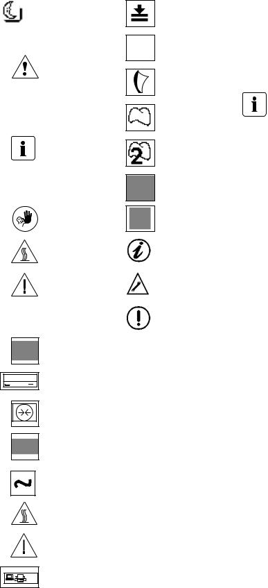
The signs and symbols in these Operating Instructions and on the furnace facilitate the finding of important points and have the following meanings:
Risks and dangers
This symbol marks
safety instructions that must be followed to
prevent injury or death. Furthermore, damage to the furnace and/or laboratory may be avoided.
Important information
This symbol marks additional information for correct and economic use of the EP 600.
Contraindication
Burn hazard
Risk of crushing
Furnace
Printer
V ~ 110-120
A max. 2.1 Fuses
Ableitstrom / Leakage current
max. 0.75 mA
T5A T12A T2A 


 250VAC
Vacuum
K-Module
(Communication
module)
Alternating current
(IEC 417)
Burn hazard
(IEC 417)
PRESSING
Mode
IPS e.max
IPS Empress Esthetic
IPS Empress Layering
Technique
IPS Empress 2
Layering Technique
IPS Empress Cosmo
IPS Empress
Staining Technique
Note
Technical malfunction
Operating error
Saving active; do not switch off the furnace
Timer active, programs cannot be started
Energy-saving mode active
|
Risk of crushing |
|
Outlet |
RS 232 |
(SELV, max. 24 VDC/A1) |
|
PC printer connection |
1.3Notes regarding the Operating Instructions
These Operating Instructions facilitate the correct, safe, and economic use of the EP 600 Press Furnace. They are divided into several, clearly structured chapters. This should enable you to locate specific topics quickly and easily.
You must read these
Operating Instructions
To inform you about risks, dangers, important information, and contraindications, these Instructions contain corresponding signs/symbols to mark important paragraphs.
We recommend keeping the Instructions in a safe place near the furnace to have immediate access to the information if necessary.
Should you lose the Operating Instructions, extra copies can be ordered at a normal fee from your local Ivoclar Vivadent Service Center.
Furnace concerned:
EP 600 Press Furnace
Target group:
Dental technicians and technologists
8

2. Safety First
This chapter is especially important for individuals who work with the EP 600 or who have to carry out maintenance or repair work. This chapter must be read and the corresponding instructions followed!
2.1 Indications
The EP 600 has been designed for pressing
IPS e.max and IPS Empress ingots and should be used for this purpose only. Uses other than the ones stipulated, e.g. cooking of food, firing of other materials, etc., are contraindicated. The manufacturer does not assume any liability for damage resulting from misuse. The user is solely responsible for any risk resulting from failure to observe these instructions.
Further instructions to assure proper use of the furnace:
–The instructions, regulations, and notes in these Operating Instructions must be observed.
–The instructions, regulations, and notes in the vacuum pump Operating Instructions must be observed.
–The furnace must be operated under the indicated environmental and operating conditions (see Chapter 9)
–The EP 600 must be properly maintained.
2.1.1 |
|
Make sure that no liquids or |
|
other foreign objects enter the |
|
|
|
|
|
|
furnace or the air vents, since |
|
Risks and dangers |
this may result in an electrical |
|
shock. |
|
|
|
2.1.2
Burn hazard
2.1.3
Risks and dangers
The furnace head should not be removed from the furnace and placed on a working surface or packaging material while it is still hot, as there is a burn hazard.
Never touch the electronic components, since a static discharge may damage them.
9

2.1.4
Risk of crushing / burn hazard
2.1.5
Risk of crushing
2.1.6
Contraindication
2.1.7
Contraindication
2.1.8
Contraindication
10
Never reach under the furnace head during operation. There is a risk of crushing and a burn hazard.
Never touch the press drive during operation. There is a risk of crushing.
Investment rings or firing trays must not be placed in the area surrounding the firing table, since they may get stuck under the furnace head. Use the sagger tray for firing trays or the cooling grid for fired investment rings.
Fired investment rings must not be placed on the sagger tray to cool. Please use the cooling grid especially designed for that purpose.
Do not place any objects on the furnace head. The opening process of the furnace head must not be obstructed.
2.1.9
Contraindication
2.1.10
Contraindication
2.1.11
Contraindication
2.1.12
Contraindication
2.1.13
Contraindication
Press cycles must not be conducted without the firing plate (50) in place.
The firing plate (50) must be correctly positioned in the firing chamber.
The furnace head is equipped with an electronic drive and must be operated with the corresponding keys. Never open or close the furnace head manually.
The air vents must be kept free from obstruction and clean at all times. If this is not done, there is a risk of overheating the furnace.
Do not bend the thermocouple (71). Do not touch the thermocouple with your fingers in order to prevent contamination (grease).
11
 Loading...