


 Loading...
UTS 3D
Universal Transferbow System
Operating Instructions
Page 3
Bedienungsanleitung
Seite 19
Mode d’emploi
Istruzioni d’uso
Pagina 51
Instrucciones de uso
Página 67
Instruções de uso
DIDATTICO MATERIALE
Page 35 |
Pagina 83 |


UTS 3D
|
|
Page |
List of Parts |
4 |
|
1. |
Introduction / Signs and Symbols |
7 |
1.1 |
Preface |
|
1.2 |
Introduction |
|
1.3. |
Notes regarding the Instructions for Use |
|
2. |
Safety First |
7 |
2.1 |
Stipulated use |
|
2.2 |
Health and safety instructions |
|
3. |
Product Description |
8 |
3.1 |
Design and functional description |
|
3.2 |
Indication, contraindication |
|
4. |
Assembly and Initial Start-Up |
9 |
4.1Unpacking and checking the contents
4.2Assembly and initial start-up
5. Handling |
10 |
5.1Earpieces
5.2Nosepiece
5.3Reference plane indicator
5.43D-registration joint
5.5Adjusting the width
5.6Additional height of the nosepiece
6. Practical Use on the Patient |
12 |
6.1Preparing the bite fork
6.2Reference plane
6.3Positioning the transferbow
6.4Positioning the nosepiece
6.5Aligning the transferbow
6.6Other versions
6.7Securing the 3D-registration joint
6.8Removing the transferbow
6.9Removing the 3D-registration joint
7. |
Maintenance, Cleaning, Diagnosis |
15 |
7.1 |
Inspection and maintenance |
|
7.2 |
Cleaning |
|
7.3 |
Cleaning instructions for the 3D-registration joint |
|
8. |
What If ..... |
16 |
8.1 |
Technical malfunctions |
|
8.2 |
Repair |
|
9. |
Product Specifications |
17 |
9.1 |
Delivery form |
|
9.2 |
Technical data |
|
10. |
Miscellaneous |
17 |
English
3

List of Parts
1.0Universal transferbow (complete)
1.1.Earpiece mounting
1.2Earpiece rod screw
1.3Side arms
1.4Side arm support
1.5Scale
1.6Multifunctional mounting
1.7Width setting screw
1.8Registration joint connection
1.9Connection for nosepiece
1.10Nosepiece holder screw
1.11Registration joint connection screw
1.12Thread for screw 3.1
2.0Individually adjustable nosepiece (complete)
2.1Nosepiece holder
2.2Nosepiece rod
2.3Nosepad holder
2.4Nosepiece rod screw
3.0Reference indicator
3.1Reference indicator screw
4.0Axis pins
4.1Thread
4.2Adapter pin for articulator
5.0Intercondylar distance (S,M,L)
6.0Earpieces (complete)
6.1Earpiece rod
6.2Threaded openings for axis pins
6.3Earpiece
6.4Threaded pin for earpieces
6.5Earpiece support
7.03D-Registration joint
7.1Connector
7.2Tommy screw
7.3Bite fork connector
7.4Bite fork connector screw
7.53D-bite fork connector
8.03D-Bite fork
8.1Connector
9.0Earpiece, black, 'large'
9.1Threaded connector
10.0Nosepads
10.1Nosepad, green (medium)
10.2Nosepad, blue (soft)
4

|
|
|
|
2.4 |
|
1.10 |
2.3 |
10.0 |
6.2 |
6.5 |
6.3 |
1.2 |
|
6.4 |
|||
2.1 |
|
|
|
2.2 |
|
|
|
|
|
|
|
|
|
|
|||
|
|
|
|
|
|
|
|
|
|
|
|
|
|
|
|
|
|
|
|
|
|
|
|
|
|
|
|
|
|
|
|
|
|
|
|
|
|
|
|
|
|
|
|
|
|
|
|
|
|
|
|
|
|
|
|
|
|
|
|
|
|
|
|
|
|
|
|
|
|
|
|
1.7 |
|
|
|
|
|
|
|
|
|
|
|
|
|
|
|
|
|
1.11 |
|
|
|
|
|
|
|
|
|
|
|
|
|
|
|
|
|
7.1 |
|
|
|
|
|
|
|
|
|
7.5 |
|
|
|
|
|
|
|
|
|
|
|
|
|
|
|
|
|
|
|
|
|
|
|
|
|
|
|
|
|
8.1 |
|
|
|
|
7.3 |
|
|
8.0 |
|
|
|
|
|
|
|
|
|
|
|
|
|
|
|
|
|
|
|
1.2 |
|||
|
|
|
|
|
|
|
|
|
|
|
|
|
|
|
|
|
|
|
|
|
|
|
|
|
7.4 |
|
|
|
|
|
|
|
|
|
|
|
|
|
|
|
|
|
|
|
|
|
|
|
|
|
|
|
1.1 |
|
|
|
|
|
|
|
|
|
|
|
|
|
|
|
|
|
6.1 |
|
|
|
|
7.2 |
|
|
|
|
|
|
|
|
|
|
|
|
|
|
|
|
|
|
|
|
|
|
|
|
|
|
|
|
|
|
|
1.2 |
6.5 |
6.3 |
4.1 |
1.9 |
2.1 |
2.3 |
10.0 |
6.3 |
|
2.4 |
4.0 |
4.2 |
3.1 |
3.0 |
|||
4.2 |
4.0 |
6.1 |
1.3 |
1.4 |
8.0 |
1.5 |
1.7 |
1.11 |
7.2 |
1.8 |
1.6 |
5.0 |
1.12 |
5

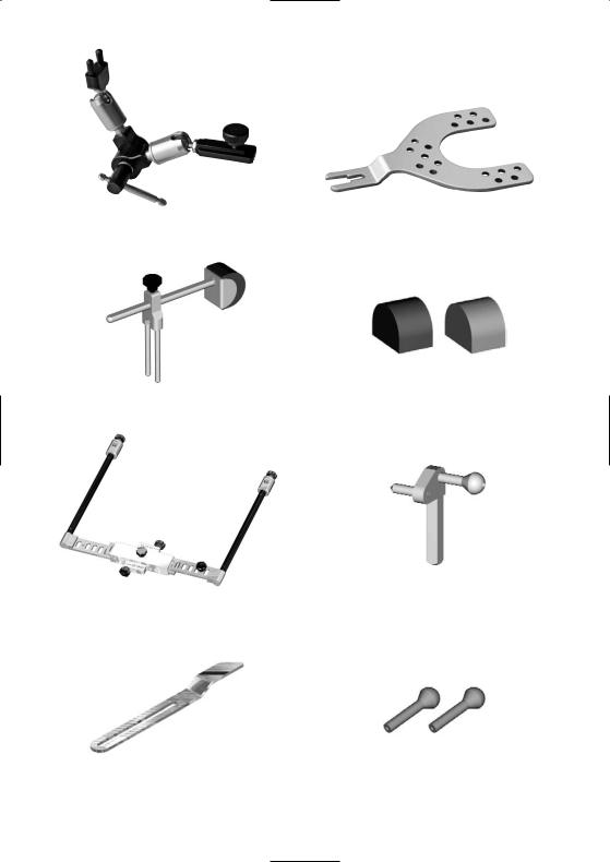
3D Registration joint (7.0) |
3D Bite fork (8.0) |
|
soft (10.2) medium (10.1) |
Individually adjustable nosepiece (2.0) |
Nosepads, 'M' and 'S' |
UTS, complete (1.0) |
Earpieces, complete (6.0) |
Reference indicator (3.0) |
Earpiece, 'large' (9.0) |
6
1. Introduction / Signs and Symbols |
2. Safety First |
1.1Preface
Dear Customer,
Thank you for having purchased the UTS 3D transferbow. This instrument is a highly technical product that is distinguished for its excellent quality and high precision.
This transferbow has been designed according to the latest industry standards. Inappropriate use may result in certain risks. Please observe the corresponding notes and become familiar with the Instructions for Use.
We wish you much success with the UTS 3D transferbow.
1.2Introduction
The signs and symbols in these Instructions for Use facilitate the finding of important points and have the following meanings:
Risks and dangers
Important information
Contraindication
1.3Notes regarding the Instructions for Use
Device concerned: UTS 3D System
Target group: Dentists, dental technologists
These Instructions for Use facilitate the correct, safe, and economic use of the UTS 3D.
Should you lose these Instructions for Use, extra copies can be ordered at a nominal fee from your local Ivoclar Vivadent Service Center.
2.1Stipulated use
This chapter is especially important for personnel who work with the UTS 3D or who have to carry out maintenance or repair work.
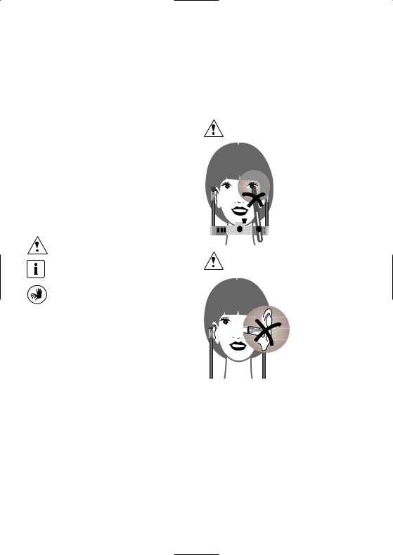
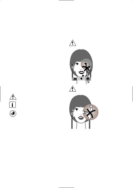
Risks and dangers:
When manipulating the transferbow on the patient, make sure than the reference indicator cannot injure the patient's eyes.
Risk and dangers:
Do not apply too much pressure when positioning the earpieces. This may result in injury to the auditory meatus.
2.2Health and safety instructions
The UTS 3D must exclusively be used for the indications listed in Chapter 3. Further instructions to ensure proper use of the transferbow:
–The instructions, regulations, and notes in these Instructions for Use must be observed.
–The UTS 3D must be properly maintained (see Chapter 7).
7

3. Product Description
3.1Design and functional description
The Universal Transferbow System is a transfer system developed on a scientific basis. It is a fact that there are larger and smaller jaws. The Bonwill triangle of various patients may differ up to 50 mm, depending on the size of the skull.
Individual, spatial model orientation by means of a transferbow takes these parameters into account and helps avoid occlusion errors.
The UTS 3D permits the spatial transfer of a patient's individual Bonwill triangle according to the joint elements of the articulator.
With its adjustable nosepiece, the UTS 3D is also suitable for model orientation according to Camper's plane (CP) and the Frankfort horizontal (FH). The adjustable earpieces also make the UTS 3D suitable for model transfer according to specific coordinates.
The Stratos 200 permits working according to these reference planes (CP and FH). For this purpose, two different registration joint holders are available (CP and FH), The registration joint holders are used according to the reference plane selected. Thanks to the registration joint holder of the Stratos 200, the transferbow no longer has to be transported to the dental laboratory. Only the 3D-registration joint and the bite fork have
to be sent to the lab.
e.g. CP version
The UTS 3D may also be directly connected to the articulator by means of the vertically adjustable type 2 support pins. For this purpose, however, the entire transferbow including the 3D-registration joint have to be sent to the dental laboratory.
3.2Indication, contraindication
Indication:
–CP version
Arbitrary skull/joint-related model orientation according to Camper's plane
–FH version
Arbitrary skull-joint related model orientation according to the Frankfort horizontal
–Other
Model orientation according to specific coordinates
Contraindication:
No contraindications are known to date, provided the UTS 3D is used strictly according to the Instructions for Use.
8
4. Assembly and Initial Start-Up
4.1Checking the contents
Check the delivery for completeness:
–1 Universal transferbow, complete
–1 Nosepiece, complete
–1 Reference indicator
–1 3D-Registration joint
–1 3D-Bite fork
–2 Earpieces with support, complete
–5 Nosepads, green (medium)
–5 Nosepads, blue (soft)
–1 Instructions for Use
4.2Assembly and initial start-up
Mount earpieces
Mount the desired earpieces (6.3) (M or L) on the threaded pins for earpieces (6.4). Loosen the earpiece rod screw (1.2) and mount the entire assembly on the earpiece mounting (1.1). Make sure the earpieces are correctly positioned.
6.3
6.4 |
|
1.2 |
|
6.1 |
1.1 |
|
Attach nosepiece with nosepads
Place the desired nosepad (10.1 or 10.2) in the nosepad holder (2.3). Insert the nosepiece rod (2.2) into the nosepiece holder (2.1).
|
2.1 |
|
1.6 |
1.8 |
1.10 |
|
1.9 |
Reference indicator
Mount the reference indicator (3.0) on the thread for screw 3.1 (1.12) by means of the reference indicator screw (3.1).
3.0 |
3.1 |
1.12
3D-registration joint with bite fork
Insert the connector (8.1) of the bite fork (8.0) into the bite fork connector (7.5) and tighten the bite fork connector screw (7.4). Insert the connector (7.1) into the registration joint connection (1.8) and secure the 3Dregistration joint (7.0) with the registration joint connection screw (1.11).
7.1 |
7.4 |
8 |
|
||
|
|
|
|
|
7.5 |
2.1
2.22.3 10.0
The nosepiece holder (2.1) may now be attached to the connection for the nosepiece (1.9) using the nosepiece holder screw (1.10) of the multifunctional mounting (1.6).
7.2 |
7.3 |
8.1 |
Axis pins
The axis pins (4.0) are mounted in the laboratory if the UTS 3D is directly connected to the articulator.
When using the UTS 3D on the patient, the axis pins (4.0) must not be used in order to prevent injury.
9
5. Handling
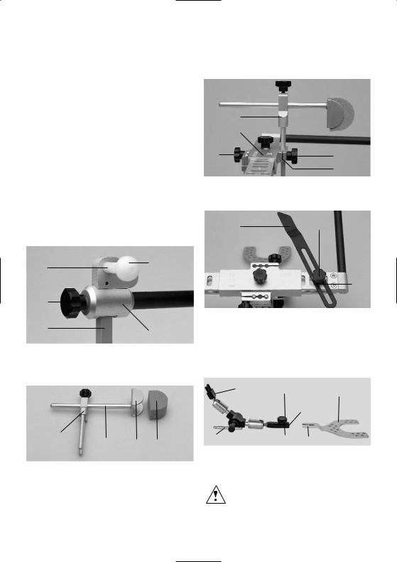
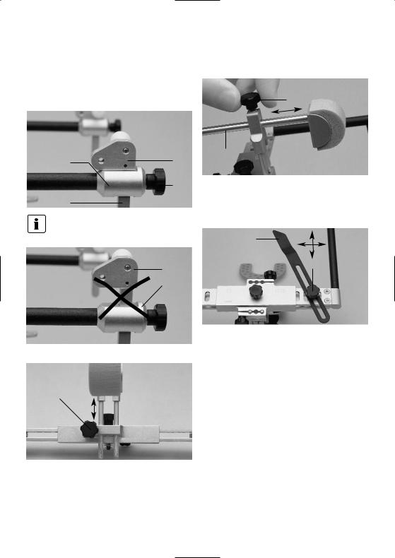
5.1Earpieces
The earpiece rod (6.1) may be adjusted by loosening the earpiece rod screw (1.2).
6.5
1.1
1.2
6.1
Please note that the earpiece support (6.5) is touching the earpiece mounting (1.1) if the CP or FH versions are used.
6.5
1.1
2.4
2.2
By loosening the nosepiece rod screw (2.4) the nosepiece rod (2.2) may be adjusted horizontally to fit the patient.
5.3Reference indicator
3.0
3.1
|
|
The reference indicator (3.0) may be adjusted to the |
|
|
patient's individual reference point by loosening the |
5.2 Nosepiece |
|
reference indicator screw (3.1). |
1.10 |
|
2.1 |
|
The height of the nosepiece holder may be adjusted to the patient's individual reference point by loosening the nosepiece holder screw (1.10).
10
5.43D-registration joint
|
7.1 |
7.4 |
8 |
|
|
||
|
|
|
|
|
|
|
7.5 |
7.2 |
|
7.3 |
8.1 |
The 3D-bite fork (8.0) is attached to the 3D-bite fork connection (7.5) by means of the 3D-bite fork connector screw (7.4).
7.3 |
7.5 |
The bite fork (older version) can be attached to the connector (7.3), as the connector is equipped with the corresponding adapter on the opposite side. For this purpose, the connector screw (7.4) has to be changed to the opposite side.
1.11
1.6
7.0
The 3D-registration joint (7.0) is secured on the multifunctional mounting (1.6) with the registration joint connection screw (1.11).
|
7.1 |
7.4 |
8 |
|
|
||
|
|
|
|
|
|
|
7.5 |
7.2 |
|
7.3 |
8.1 |
The tommy screw (7.2) secures the 3D-registration joint.
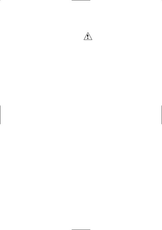
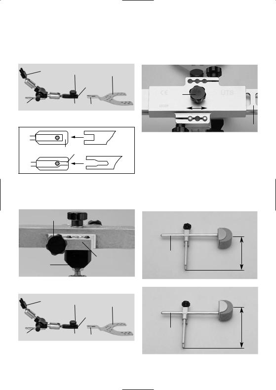
5.5Adjusting the width
1.7
5.0
The width of the transferbow can be adjusted by loosening the 'width setting' screw. If the minimum width is not sufficient, the black earpieces 'L' (9.0) can be used. In this way, an additional 20 mm of space is available.
5.6Additional height in the area of the nosepiece
2.2
If the nosepiece rod (2.2) is rotated by 180°, an additional 10 mm is gained.
2.2
11
6. Practical Use on the Patient
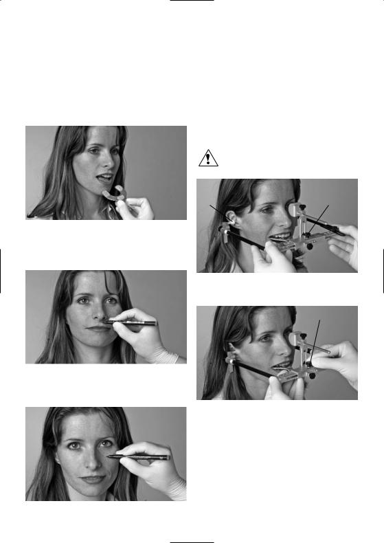
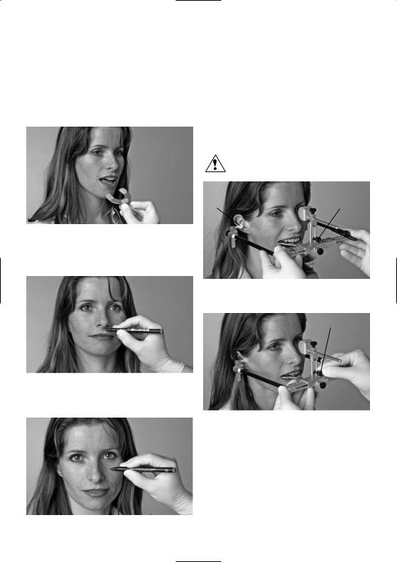
6.1Preparing the bite fork
Coat the bite fork with sufficient hard wax (warmed) or silicone. Press wax or silicone on the maxillary tooth row. Make sure that clear occlusal support on both sides is provided.
6.2Reference plane
6.2.1 CP version
Camper's plane runs from the spina nasalis to the lower edge of the external auditory meatus. Mark the spina nasalis.
6.2.2 FH version
The Frankfort horizontal runs from the suborbital point to the upper outer edge of the auditory meatus. Mark the orbital point.
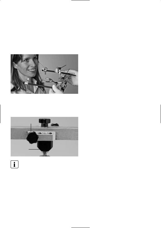
6.3Positioning the transferbow
The patient should be in an upright position. Loosen the width setting screw (1.7) and completely open the transferbow. Introduce the earpieces (6.3) into the
external auditory meatus by slowly pushing the side arms together. To relieve some of the weight, the patient may support the UTS 3D by holding the side arms with both hands.
Do not apply too much pressure when positioning the earpieces.
6.3 |
1.7 |
Next, tighten the width setting screw (1.7) to set the width.
1.7
12

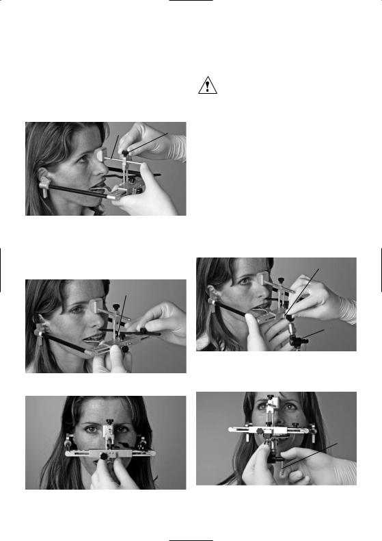
6.4Positioning the nosepiece
With the 'nosepiece' screw open (2.4), exert slight pressure with the thumb to position the nosepiece rod (2.2) on the glabella so that the bow sits firmly.
2.2 |
2.4 |
|
6.5Aligning the transferbow
Align the transferbow by vertical adjustment of the nosepiece, pointing with the reference indicator either at the spina nasalis (for CP) or at the orbital point (for FH).
CP version = spina nasalis
1.10
FH version = orbital point
When manipulating the reference indicator (3.0), make sure to observe a certain distance to the eye of the patient in order to prevent injury.
6.6Other versions
By means of the vertically adjustable earpieces, the UTS 3D-transferbow is also suitable for model transfer according to specific coordinates. Please refer to the literature for further details on this subject.
6.7Securing the 3D-registration joint
Check again if the transferbow is tightly positioned with regard to the relevant reference points. Attach the 3Dbite fork (8.0) to the open 3D-registration joint (7.0) and position the 3D-bite fork on the mandibular tooth row. Additional support for the 3D-bite fork may be provided by cotton rolls. The 3D-registration joint (7.0) is now secured at the 3D-registration joint connection (1.8).
1.8
7.0
Tighten the tommy screw (7.2) for the rotary joint. The registration procedure is now complete and the corresponding parameters are recorded in the 3Dregistration joint.
7.2
13
6.8Removing the transferbow
Loosen the width setting screw (1.7) for the nosepiece (1.9). Pull the side arms outward and instruct the patient to open the mouth. Now the whole apparatus including the registration can be removed.
1.9
1.7
6.9Removing the 3D-registration joint
Loosen the registration joint connection screw (1.11) and remove the 3D-registration joint (7.0).
1.11
7.0
The transferbow may be used in combination with the Gnathometer 'M' or the Centric Tray in the manner described above.
14
7. Maintenance, Cleaning, and Diagnosis
This chapter describes the user maintenance and cleaning procedure for the UTS 3D-transferbow. This list contains only tasks that may be performed by dental personnel.
All other tasks must be performed by qualified service personnel at a certified Ivoclar Vivadent Service Center.
7.1Inspection and maintenance
The time for these maintenance procedures depends on the frequency of use and the working habits of the users. For that reason, the recommended times are only approximate values.
7.2 Cleaning
What |
When |
Cleaning material |
|
|
|
Screws that are |
If required |
Rinse with hot |
contaminated |
|
water and dry |
with wax or |
|
with a dry cloth |
plaster. |
|
|
|
|
|
Screws that are |
If required |
Clean with a |
contaminated |
|
cloth. |
with silicone. |
|
|
|
|
|
3D-bite fork that |
After every use |
see chapter 7.3 |
has come into |
|
|
contact with |
|
|
saliva or blood. |
|
|
|
|
|
3D-registration |
After every use |
Clean with a |
joint |
|
spray disinfectant |
|
|
|
UTS 3D- |
After every use |
Clean with a |
transferbow |
|
spray disinfectant |
|
|
|
Nosepads |
After every use |
Use new nosepad |
|
|
(nosepads are |
|
|
disposable) |
Earpieces |
After every use |
Autoclaving |
|
|
device. Please |
|
|
observe the |
|
|
corresponding |
|
|
instructions. |
|
|
|
Avoid contact with strong acids or solvents (e.g. MMA). In this way, damage to the surfaces can be prevented.
7.3Cleaning instructions for the 3D-registration joint
–After every use or contact with saliva or blood, wipe with a disinfectant.
–Only use disinfectants that are suitable for stainless steel and light metals.
–Avoid any contact with strong acids, bases or solvents.
–Do not clean with ultrasonic bath, water, steam jet or sterilization units.
15

8. What if....
This chapter will help you to recognize errors and take appropriate measures or, if possible, to perform some repairs.
8.1Technical errors
Description |
Double check |
Corrective action |
Patient has pressure sores and complains about pain of the nose
Is the nosepad in place? |
Use nosepad |
Patient complains about pain in the ear
Is the width of the transferbow too narrow?
Do not close the transferbow too tightly.
The reference to the corresponding |
Were the earpieces correctly mounted |
When recording according to the CP |
plane (CP or FH) has not been |
so that they came into contact with the |
and FH method, the earpieces must |
correctly recorded |
earpiece support? |
always come into contact with the |
|
|
earpiece support. |
|
|
|
Surface of the transferbow is |
Was the surface cleaned with acid or a |
Do not use acids or solvents to clean |
damaged |
solvent? |
the transferbow. |
|
|
|
Surface of the transferbow is scratched
Was a sharp instrument used?
Do not use sharp instruments in conjunction with the transferbow.
8.2Repair
Repairs may only be carried out by a certified Ivoclar Vivadent Service Center. Please refer to the addresses on the last page of these Instructions for Use.
If repairs during the warranty period are not carried out by a certified Ivoclar Vivadent Service Center, the warranty will expire immediately. Please refer to the warranty regulations for more details.
16
9. Product Specifications |
10. Miscellaneous |
9.1Delivery form
–1 Universal transferbow with set screws
–1 3D-registration joint with tommy screws
–1 3D-Bite fork
–1 Nosepiece
–5 Nosepads, green (medium)
–5 Nosepads, blue (soft)
–2 Earpieces, white
–2 Earpieces, black (large)
–1 Reference indicator
–2 Axis pins
–1 Instructions for Use
The delivery form may vary from country to country.
Recommended accessories
–UTS type 2 support pins for direct model transfer to the articulator
Additional accessories and spare parts
–3D-Bite fork (8.0)
–3D-Registration joint (7.0)
–Nosepads 'medium' (10.1)
–Nosepads 'soft' (10.2)
–Earpieces (6.3)
–Earpieces 'L' (9.0)
9.2 Technical data
Weights: |
|
Nosepiece: |
25 g |
3D-Registration joint: |
94 g |
UTS 3D-transferbow: |
160 g |
Materials: |
|
Metal parts: |
aluminium, steel |
Side arms: |
carbon composite material |
Earpieces: |
DELRIN resin |
Adjustment possibilities |
|
|
Adjustable width with |
|
|
earpieces 'L': |
107 mm to 180 mm |
|
Adjustable width: |
87 mm to 160 mm |
|
Adjustable nosepiece height: |
|
85 mm |
Adjustable nosepiece length: |
|
22 mm |
Adjustable earpiece height: |
|
22 mm |
Adjustable reference indicator height: |
66 mm |
|
Tips for model transfer to the Stratos articulator
Please observe the Operating Instructions of the Stratos articulator or the corresponding literature.
This device has been developed solely for use in dentistry. Start-up and operating should be carried out strictly according to the Instructions for Use. Liability cannot be accepted for damages resulting from misuse or failure to observe the Instructions. The user is solely responsible for testing the apparatus for its suitability for any purpose not explicitly stated in the Instructions. Descriptions and data constitute no warranty of attributes and are not binding.
17

18

UTS 3D
|
|
Seite |
Geräteübersicht, Teileverzeichnis |
20 |
|
1. |
Einleitung und Zeichenerklärung |
23 |
1.1 |
Vorwort |
|
1.2 |
Einleitung |
|
1.3 |
Angaben zur BA |
|
2. |
Sicherheit geht vor |
23 |
2.1Bestimmungsgemässe Verwendung
2.2Sicherheitsund Gefahrenhinweise
3.Produktbeschreibung
3.1Aufbau und Funktionsbeschreibung
3.2Indikation, Kontraindikation
4. Installation und erste Inbetriebnahme |
25 |
4.1Auspacken und Lieferumfang prüfen
4.2Zusammenbau und erste Inbetriebnahme
5. Handhabung, Bedienung |
26 |
5.1Ohrpelotten
5.2Nasensteg
5.3Referenzebenenzeiger
5.43D-Registriergelenk
5.5Breiteneinstellung
5.6Zusätzlicher, vertikaler Höhengewinn beim Nasensteg
6. Praktische Anwendung am Patienten |
28 |
6.1Bissgabel vorbereiten
6.2Orientierungsebene
6.3Anlegen des Transferbogens
6.4Anlegen der Nasenauflage
6.5Ausrichten des Transferbogens
6.6Andere Versionen
6.7Befestigen des 3D-Registriergelenkes
6.8Abnehmen des Transferbogens
6.9Entfernen des 3D-Registriergelenkes
7. Unterhalt, Reinigung, Diagnose |
31 |
7.1Kontrollund Unterhaltsarbeiten
7.2Reinigungsarbeiten
7.3Pflegehinweise zu 3D-Registriergelenk
8. Was ist, wenn.... |
32 |
8.1Technische Störungen
8.2Reparaturarbeiten
9. Produktspezifikationen |
33 |
9.1Lieferform
9.2Technische Daten
10. Sonstiges |
33 |
Deutsch
19

Geräteübersicht / Teileverzeichnis
1.0UTS Grundbogen (kpl.)
1.1Ohrpelottenhalterung
1.2Schraube "Ohrpelottenstange"
1.3Seitenarme
1.4Seitenarmträger
1.5Basislineal
1.6Aufnahmeteil
1.7Schraube "Breitenverstellung"
1.8Anschluss für Registriergelenk
1.9Anschluss für Nasenstütze
1.10Schraube "Nasenstützenhalter"
1.11Schraube "Registriergelenkanschluss"
1.12Gewinde für Schraube 3.1
2.0Individuell, verstellbare Nasenstütze (kpl.)
2.1Nasensteghalter
2.2Nasenstützenstange
2.3Nasenpolsterhalter
2.4Schraube "Nasenstützenstange"
3.0Referenzpunktzeiger
3.1Schraube "Referenzpunktzeiger"
4.0Achsenstifte
4.1Gewinde
4.2Adapterspitze für Artikulator
5.0Intercondylarabstand (S,M,L)
6.0Ohrpelotten (kpl.)
6.1Ohrpelottenstange
6.2Gewindebohrungen für Achsenstifte
6.3Ohrpelotte
6.4Gewindestift für Ohrpelotten
6.5Ohrpelottenträger
7.03D-Registriergelenk
7.1Anschlussteil
7.2Knebelschraube
7.3Anschluss für Bissgabel
7.4Schraube "Bissgabelanschluss"
7.5Anschluss für 3D Bissgabel
8.03D-Bissgabel
8.1Anschluss
9.0Ohrpelotte schwarz "large"
9.1Gewindeanschluss
10.0Nasenpolster
10.1Nasenpolster grün (medium)
10.2Nasenpolster blau (soft)
20
|
|
|
|
2.4 |
|
1.10 |
2.3 |
10.0 |
6.2 |
6.5 |
6.3 |
1.2 |
|
6.4 |
||||
2.1 |
|
|
|
2.2 |
|
|
|
|
|
|
|
|
|
|
|
|||
|
|
|
|
|
|
|
|
|
|
|
|
|
|
|
|
|
|
|
|
|
|
|
|
|
|
|
|
|
|
|
|
|
|
|
|
|
|
|
|
|
|
|
|
|
|
|
|
|
|
|
|
|
|
|
|
|
|
|
|
|
|
|
|
|
|
|
|
|
|
|
|
|
|
|
|
1.7 |
|
|
|
|
|
|
|
|
|
|
|
|
|
|
|
|
|
|
1.11 |
|
|
|
|
|
|
|
|
|
|
|
|
|
|
|
|
|
|
7.1 |
|
|
|
|
|
|
|
|
7.5 |
|
|
|
|
|
|
|
||
|
|
|
|
|
|
|
|
|
|
|
|
|
|
|
|
|
||
|
|
|
|
8.1 |
|
|
|
|
7.3 |
|
|
|
8.0 |
|
|
|
|
|
|
|
|
|
|
|
|
|
|
|
|
|
|
|
|
1.2 |
|||
|
|
|
|
|
|
|
|
|
|
|
|
|
|
|
|
|
|
|
|
|
|
|
|
|
|
7.4 |
|
|
|
|
|
|
|
|
|
|
|
|
|
|
|
|
|
|
|
|
|
|
|
|
|
|
|
|
|
1.1 |
|
|
|
|
|
|
|
|
|
|
|
|
|
|
|
|
|
|
6.1 |
|
|
|
|
7.2 |
|
|
|
|
|
|
|
|
|
|
|
|
|
|
|
|
|
|
|
|
|
|
|
|
|
|
|
|
|
|
|
|
|
1.2 |
6.5 |
6.3 |
4.1 |
1.9 |
2.1 |
2.3 |
10.0 |
|
6.3 |
|
2.4 |
4.0 |
4.2 |
3.1 |
3.0 |
|||
4.2 |
4.0 |
6.1 |
1.3 |
1.4 |
8.0 |
1.5 |
1.7 |
1.11 |
7.2 |
1.8 |
1.6 |
5.0 |
1.12 |
21
3D-Registriergelenk (7.0) |
3D-Bissgabel (8.0) |
soft (10.2) medium (10.1)
Nasenstütze (kpl.) (2.0) |
Nasenpolster |
Grundbogen (kpl.) (1.0) |
Ohrpelotte (kpl.) (6.0) |
Referenzpunktzeiger (3.0) |
Ohrpelotte (L) (9.0) |
22
1. Einleitung und Zeichenerklärung |
2. Sicherheit geht vor |
1.1Vorwort
Sehr geehrter Kunde,
Es freut uns, dass Sie sich für den Kauf des UTS 3D Transferbogens entschieden haben. Bei diesem Instrument handelt es sich um ein technisch hochstehendes Produkt . Gute Qualität und hohe Präzision zeichnen dieses Produkt aus.
Das Gerät wurde nach dem heutigen Stand der Technik gebaut. Bei unsachgemässer Handhabung können jedoch Gefahren entstehen. Bitte beachten Sie dazu die entsprechenden Hinweise und lesen Sie bitte die Bedienungsanleitung.
Wir wüschen Ihnen nun viel Freude und Erfolg mit dem UTS 3D Transferbogen.
1.2Einleitung
Die Symbole in der Verarbeitungsanleitung erleichtern Ihnen das Auffinden wichtiger Punkte und geben Ihnen folgende Hinweise:
Gefahren und Risiken
Wichtige Information
Nicht zulässige Anwendung
1.3Angaben zur Bedienungsanleitung
Zutreffendes Gerät: UTS 3D
Zielgruppe: Zahnärzte, zahnmedizinisches Fachpersonal
Die Bedienungsanleitung dient zur sicheren, sachgerechten und wirtschaftlichen Nutzung des Gerätes.
Bei eventuellem Verlust kann die BA gegen eine Schutzgebühr über die entsprechende Servicestelle bezogen werden.
2.1Bestimmungsgemässe Verwendung
Dieses Kapitel empfehlen wir allen Personen, welche mit dem Gerät arbeiten oder Unterhaltund Servicearbeiten an diesem Instrument durchführen.
Risiken und Gefahren:
Bei Manipulationen mit dem UTS 3D am Patienten immer darauf achten, dass der Referenzebenenzeiger das Auge nicht verletzt.
Risiken und Gefahren:
Ohrpelotten nicht mit Gewalt oder mit zu starkem Druck in den Gehörgang drücken. Dadurch könnte das Gehörorgan verletzt werden.
2.2Sicherheitsund Gefahrenhinweise
Der UTS 3D darf ausschliesslich für den im Kapitel 3 beschriebenen Bereich verwendet werden. Zur bestimmungsgemässen Verwendung gehört zudem:
–Die Beachtung der Anweisungen, Vorschriften und Hinweise der vorliegenden BA
–Die korrekte Instandstellung und Unterhalt des Gerätes (siehe Kapitel 7)
23

3. Produktbeschreibung
3.1Aufbau und Funktionsbeschreibung
Das UTS 3D-System ist ein auf wissenschaftlicher Basis entwickeltes Übertragungssystem. Tatsache ist, dass es kleinere und grössere Kiefer gibt. Je nach Schädelgrösse des Patienten sind bezüglich dem Bonwill-Dreieck Abweichungen von bis zirka 50 mm in Bezug auf den Mittelwert möglich.
Im Stratos 200 kann nach diesen Bezugsebenen (CE und FH) gearbeitet werden. Es stehen für diesen Zweck zwei unterschiedliche Registriergelenkträger (CE und FH) zur Verfügung. Je nach gewählter Referenzebene muss der entsprechende Registriergelenkträger verwendet werden. Durch diese Möglichkeit kann auf den Versand des kompletten Transferbogens ins Labor verzichtet werden. Es muss nur das 3D-Registriergelenk sowie die Bissgabel dem Labor zugestellt werden.
Eine individuelle, räumliche Übertragung der Modelle mittels Transferbogen berücksichtigt die individuellen Parameter und verhindert okklusale Übertragungsfehler.
Das UTS 3D-System ermöglicht die Übertragung der räumlichen Lage des patientenindividuellen "Bonwillschen" Dreiecks zu den Gelenkelementen des Artikulators.
z.B. CE-Version
Mit den höhenverstellbaren Stützstiften Typ 2 kann das UTS 3D-System jedoch auch direkt an den Artikulator angeschlossen werden. Bei diesem Verfahren muss jedoch der ganze Transferbogen mit 3D-Registriergelenk und Bissgabel dem Labor zugestellt werden.
Das UTS 3D-System eignet sich durch die verstellbare Nasenstütze für die Übertragung zur Camperschen Ebene (CE), oder der Frankfurter Horizontalen (FH). Mit der Möglichkeit der verstellbaren Ohrpelotten können auch koordinatenbezogene Modellübertragungen durchgeführt werden.
3.2Indikation, Kontraindikation
Indikation:
–Version CE
Arbiträre, schädel-/gelenkbezogene Orientierung der Modelle nach der Camperschen Ebene
–Version FH
Arbiträre, schädel-/gelenkbezogene Orientierung der Modelle nach der Frankfurter Ebene
–Sonstige
Koordinatenbezogene Modellübertragung
Kontraindikation:
Bei sachgemässer Anwendung gemäss der BA sind derzeit keine Kontraindikationen bekannt.
24

4. Installation und erste Inbetriebnahme
4.1Auspacken und Lieferumfang prüfen
Bitte prüfen Sie nun, ob der Lieferumfang komplett ist.
–1 Grundbogen kpl.
–1 Nasensteg kpl.
–1 Referenzebenenzeiger
–1 3D Registriergelenk
–1 3D Bissgabel
–2 Ohrpelotten mit Halterung kpl.
–5 Nasenpolster grün (medium)
–5 Nasenpolster blau (soft)
–1 Bedienungsanleitung
4.2Zusammenbau und erste Inbetriebnahme
Der UTS ist teilweise bereits vormontiert. Ohrpelotten montieren:
Montieren Sie die gewünschte Ohrpelotte (6.3) (M oder L) am Gewindestift für Ohrpelotten (6.4). Lösen Sie die Schraube (1.2) und befestigen sie das komplette Teil in der Ohrpelottenhalterung (1.1). Bitte beachten Sie dabei die korrekte Positionierung der Ohrpelotten.
6.3
6.4 |
|
1.2 |
|
6.1 |
1.1 |
|
Nasenstütze mit Nasenpolster montieren:
Drücken Sie das gewünschte Nasenpolster (10.1 oder 10.2) in den Nasenpolsterhalter (2.3).
|
2.1 |
|
1.6 |
1.8 |
1.10 |
|
1.9 |
Referenzebenenzeiger:
Befestigen Sie den Referenzebenenzeiger (3.0) mit der Schraube (3.1) am Gewinde für Schraube 3.1 (1.12).
3.0 |
3.1 |
1.12
3D Registriergelenk mit 3D Bissgabel:
Stecken Sie die 3D-Bissgabel (8.0) mit dem Anschluss (8.1) in das Anschlussteil für 3D Bissgabel (7.5) und fixieren Sie das Teil mit der Schraube (7.4). Stecken Sie das Anschlussteil (7.1) in den Anschluss für 3D Registriergelenk (1.8) und fixieren das 3D Registriergelenk (7.0) mit der Schraube (1.11).
7.1 |
7.4 |
8 |
|
||
|
|
|
|
|
7.5 |
2.1
2.22.3 10.0
Stecken Sie nun die Nasenstützenstange (2,2) in den Nasenstützenhalter (2.1). Der Nasenstützenhalter (2.1) kann nun im Anschluss für Nasenstütze (1.9) mittels der Schraube (1.10) am Aufnahmeteil (1.6) fixiert werden.
7.2 |
7.3 |
8.1 |
Achsenstifte:
Die Achsenstifte (4.0) müssen nur im Labor fixiert werden, wenn der UTS 3D direkt am Artikulator angeschlossen werden soll.
Um körperliche Verletzungen am Patienten zu verhindern, dürfen diese Achsenstifte (4.0) bei der Transferbogenanlage am Patienten nicht verwendet werden
25

5. Handhabung, Bedienung
5.1Ohrpelotten
Durch Lösen der Feststellschraube (1.2) kann die Ohrpelottenstange (6.1) verstellt werden.
6.5
1.1
1.2
6.1
Bitte beachten Sie, dass bei der Version CE und Version FH der Ohrpelottenträger (6.5) ganz auf der Ohrpelottenhalterung (1.1) aufliegt.
6.5
1.1
2.4
2.2
Durch Lösen der Schraube (2.4) kann die Nasenstützenstange (2.2) in horizontaler Richtung dem Patienten angepasst werden.
5.3Referenzebenenzeiger
3.0
3.1
|
|
Durch Lösen der Schraube (3.1) kann der Referenz- |
|
|
ebenenzeiger (3.0) individuell an den Referenzpunkt des |
5.2 Nasensteg |
|
Patienten ausgerichtet werden. |
1.10 |
|
2.1 |
|
Durch Lösen der Schraube (1.10) kann der Nasensteghalter (2.1) in der Höhe verstellt und auf den individuellen Referenzpunkt des Patienten eingestellt werden.
26
5.43D Registriergelenk
|
7.1 |
7.4 |
8 |
|
|
||
|
|
|
|
|
|
|
7.5 |
7.2 |
|
7.3 |
8.1 |
Die 3D-Bissgabel (8.0) wird mittels der Fixierschraube (7.4) am Anschluss für 3D Bissgabel (7.5) fixiert.
7.3 |
7.5 |
Die Bissgabel (ältere Version) kann am Anschluss (7.3) fixiert werden, da der Anschluss auf der gegenüberliegenden Seite mit dem entsprechenden Adapter ausgerüstet ist. Dazu muss auch die Fixierschraube (7.4) auf die gegenüberliegende Seite gewechselt werden.
5.5Breiteneinstellung
1.7
5.0
Durch lösen der Schraube (1.7) kann der Transferbogen in der Breite verstellt werden. Sollte die minimale Breite nicht ausreichen, können die schwarzen Ohrpelotten "L" (9.0) verwendet werden. Dadurch können zusätzliche
20 mm Verstellweg gewonnen werden.
5.6Zusätzlicher, vertikaler Höhengewinn beim Nasensteg
Wird die Nasenstützenstange (2.2) um 180° gedreht, kann ein zusätzlicher, vertikaler Verstellweg (10 mm) gewonnen werden.
1.11
2.2
1.6
7.0
Das 3D-Registriergelenk (7.0) wird mittels der Schraube (1.11) am Aufnahmeteil (1.6) fixiert werden.
|
7.1 |
7.4 |
8 |
|
|
||
|
|
|
|
|
|
|
7.5 |
7.2 |
|
7.3 |
2.2 |
|
8.1 |
Mit der Knebelschraube (7.2) kann das 3D-Registrier- gelenk fixiert werden.
27
6. Praktische Anwendung am Patienten
6.1Bissgabel vorbereiten
Bissgabel mit erwärmten Hartwachs oder Silikon beschichten und auf die OK-Zahnreihe drücken. Eine eindeutige okklusale Abstützung muss gewährleistet sein.
6.2Orientierungsebene
6.2.1 Version CE
Die Campersche Ebene verläuft von der Spina nasalis zum unteren Rand des äusseren Gehörganges. Markieren Sie den Punkt "Spina nasalis".
6.2.2 Version FH
Die Frankfurter Horizontale verläuft vom Suborbitalpunkt zum oberen äusseren Rand des Gehörganges. Markieren Sie die den Punkt "Orbitalpunkt".
6.3Anlegen des Transferbogens
Der Patient sollte in aufrechter Position sein.
Schraube (1.7) lösen und Transferbogen mit der Breitenverstellung ganz öffnen. Ohrpelotten (6.3) durch langsames Zusammenschieben der Breitenverstellung in die äusseren Gehörgänge einführen. Der Patient kann den UTS zur Gewichtsentlastung mit beiden Händen an den Seitenarmen stützen.
Ohrpelotten nicht mit Gewalt oder mit zu starkem Druck in den Gehörgang drücken.
6.3 |
1.7 |
Anschliessend die Breitenverstellung mit der Schraube (1.7) fixieren.
1.7
28
6.4Anlegen der Nasenauflage
Bei geöffneter Schraube (2.4) die Nasenstützenstange (2.2) mit dem Daumen mit leichtem Druck so an der Glabella positionieren, dass der Bogen straff anliegt.
2.2 |
2.4 |
|
6.5Ausrichten des Transferbogens
Durch die vertikale Höhenverstellung (1.10) kann der Transferbogen zur gewünschten Referenzebene (CE oder FH) ausgerichtet werden.
CE-Version = Spina nasalis
1.10
Achten Sie bei den Manipulationen mit dem Referenzebenenzeiger (3.0) stets darauf, dass Sie genügend Abstand zum Patientenauge einhalten und das Auge nicht verletzen.
6.6Andere Versionen
Mittels der höhenverstellbaren Ohrpelotten kann der UTS 3D-Transferbogen auch noch für die koordinatenbezogene Modellübertragung verwendet werden. Weitere Angaben zu diesem Thema finden Sie in der entsprechenden Fachliteratur.
6.7Befestigen des 3 D Registriergelenkes
Prüfen Sie nochmals den korrekten Sitz des Transferbogens gegenüber der Referenzpunkten. Befestigen Sie die 3D Bissgabel (8.0) am geöffneten 3D-Registriergelenk (7.0) und setzen Sie die Bissgabel (8.0) auf die Zahnreihe auf. Mittels Watterollen auf der UK-Zahnreihe kann die Bissgabel zusätzlich gestützt werden. Nun kann das 3DRegistriergelenk (7.0) am Anschluss für das 3D-Registrier- gelenk (1.8) befestigt werden.
1.8
7.0
Ziehen Sie nun die Knebelschraube (7.2) für das Drehgelenk an. Nun ist die Registrierung abgeschlossen und
die Parameter im 3D-Registriergelenk gespeichert.
FH-Version = Orbitalpunkt
7.2
29

6.8Abnehmen des Transferbogens
Lösen Sie die Schraube (1.7) für die Breitenverstellung und die Schraube am Nasensteg (1.9). Ziehen Sie den Transferbogen mit der Breitenverstellung auseinander und fordern Sie den Patienten auf, den Mund zu öffnen.
Nun kann der ganze Transferbogen mit dem Registrat vom Patienten entfernt werden.
1.9
1.7
6.9Entfernen des 3D-Registriergelenkes
Lösen Sie die Schraube (1.11) und entfernen Sie das 3DRegistriergelenk. (7.0)
1.11
7.0
Auf die gleiche Art und Weise kann der Transferbogen in Kombination mit dem Gnathometer "M" oder dem Centric Tray verwendet werden.
30
Loading...