


 CAD
CAD
|
|
|
ceramic |
|
||
|
|
|
|
|||
|
|
|
|
|||
all |
|
|||||
|
you |
need |
|
|||
|
all |
|
|
|||
|
|
|
|
|||
I N S T R U C T I O N S F O R U S E
L A B S I D E

Table of Contents
PRODUCT |
INFORMATION |
PRACTICAL NOTES ON PROCESSING
INFOR- |
MATION |
3 IPS e.max System – one system for every indication
CAD 4 Product Information
Material
Usage
Composition
Scientific Data
Block Concept
CAD/CAM Partners
9Clinical steps, model preparation, CAD/CAM process
Overview of the Clinical Working Steps, Fabrication Process
Shade Determination — Tooth Shade, Shade of the Prepared Tooth Preparation Guidelines
Model and Tooth Preparation Layer Thicknesses
Design Guidelines for the Restoration CAD/CAM Processing
18Staining Technique
Finishing
Crystallization and Stain/Glaze Firing
–Option A: Crystallization and Stain/Glaze Firing in One Step with Glaze Paste
–Option B: Crystallization and Stain/Glaze Firing in One Step with Glaze Spray
–Option C: Crystallization and Separate Stain/Glaze Firing
35Cut-Back Technique
Finishing and Preparation for Crystallization Crystallization
Veneering with IPS e.max Ceram
45Layering Technique
Finishing and Preparation for Crystallization Crystallization
Veneering with IPS e.max Ceram
53Seating and Follow-Up Care
Possibilities for Cementation Preparing for Cementation Care notes
CAD 56 General Information
Frequently Asked Questions
Table on Block Selection
Crystallization and Firing Parameters
2
IPS
e.max® System –
all you need
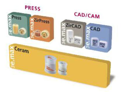
IPS e.max is an innovative all-ceramic system which covers the entire all-ceramic indication range – from thin veneers to 10-unit bridges.
IPS e.max delivers high-strength and highly esthetic materials for the Press and the CAD/CAM technologies. The system consists of innovative lithium disilicate glass-ceramics used mainly for singletooth restorations and high-strength zirconium oxide for large-span bridges.
Every patient situation presents its own requirements and objectives. IPS e.max meets these requirements. Due to the system components you obtain exactly what you need.
–The components of the Press technology include the highly esthetic IPS e.max Press lithium disilicate glass-ceramic ingots and the IPS e.max ZirPress fluorapatite glass-ceramic ingots for the fast and efficient press-on-zirconia technique.
–Depending on the case requirements, two types of materials are available for CAD/CAM techniques: the innovative IPS e.max CAD lithium disilicate blocks and the high-strength zirconium oxide IPS e.max ZirCAD.
–The nano-fluorapatite layering ceramic IPS e.max Ceram, which is used to characterize/veneer all IPS e.max components – glass or oxide ceramics – completes the IPS e.max System.
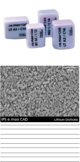
IPS e.max CAD
The shades and translucency levels of the IPS e.max CAD blocks are based on the overarching IPS e.max shade system. The system has a flexible design and can be used in conjunction with the A-D, Chromascop as well as Bleach BL shade guides.
The shades of the Press ingots and CAD/CAM blocks offered in the IPS e.max System are all coordinated with each other. They are available in different degrees of opacity and/or translucency. The selection of the translucency level is based on the clinical requirements (shade of the prepared tooth, desired tooth shade) presented by the patient, as well as the desired processing technique (layering, cut-back, staining technique).
The more opaque HO (only IPS e.max Press) and MO blocks are predominantly suitable for the layering technique, while the more translucent LT and HT blocks are used for the cut-back and also the staining technique.
3
IPS
e.max® CAD
Product Information
Material
IPS e.max CAD is a lithium disilicate glass-ceramic block for the CAD/CAM technique. It is fabricated using an innovative process which provides an impressive homogeneity of the material. The block can be processed very easily in a CAD/CAM unit in this crystalline intermediate stage. The typical and striking colour of IPS e.max CAD ranges from whitish to blue and bluish-grey. This shade is a result of the composition and the microstructure of the
glass-ceramic. The strength of the material in this processable intermediate phase is 130150 MPa. After the IPS e.max CAD blocks are milled, the restoration is crystallized in an Ivoclar Vivadent ceramic furnace (e.g. Programat® P300, P500, P700). Unlike with some other CAD/CAM ceramics, the approximately 20-31-minute, easy- to-conduct crystallization process neither causes any major shrinkage, nor are any complicated infiltration processes required. The crystallization process at 840-850°C (1544 -1562°F) results in a transformation of the microstructure, during which lithium disilicate crystals grow in a controlled manner. The densification of 0.2% is accounted for in the CAD software and taken into account upon milling.
The final physical properties, such as the strength of 360 MPa and the corresponding optical properties, are achieved through the transformation of the microstructure.
CTE (100-400°C) [10-6 |
/K] |
10.2 |
CTE (100-500°C) [10-6 |
/K] |
10.5 |
Flexural strength (biaxial) [MPa]* |
360 |
|
Fracture toughness [MPa m0.5] |
2.25 |
|
Modulus of elasticity [GPa] |
95 |
|
Vickers hardness [MPa] |
|
5800 |
|
|
|
Chem. solubility [µg/cm2]* |
40 |
|
Crystallization temperature [°C/°F] |
840–850/1544-1562 |
|
*according to ISO 6872 |
|
|
4
Usage |
Composition |
Indications
–Veneers
–Inlays
–Onlays
–Partial crowns
–Crowns in the anterior and posterior region
–Implant superstructures for single-tooth restorations (anterior and posterior region)
–Primary telescope crowns
Contraindications
–Full veneers on molar crowns
–Very deep sub gingival preparations
–Patients with substantially reduced residual dentition
–Bruxism
–Any other use not listed in the indications
Important processing restrictions
Failure to observe the following restrictions may compromise the results achieved with IPS e.max CAD:
–The frameworks must not fall below the required minimum thickness.
–Do not mill the blocks with non-compatible CAD/CAM systems.
–Crystallization must not be conducted in a ceramic furnace that has not been approved and/or recommended.
–Crystallization must not be conducted in a ceramic furnace that has no vacuum function.
–Crystallization must not be conducted in a ceramic furnace that has not been calibrated.
–Crystallization must not be conducted in a high-temperature furnace (e.g. Sintramat).
–Do not mix IPS e.max CAD Crystall./Glaze, Shades and Stains with other dental ceramics (e.g. IPS e.max Ceram Glaze, Stains and Essence).
–Do not layer with a veneering ceramic other than IPS e.max Ceram.
Side effects
If the patient is known to be allergic to any of the components of IPS e.max CAD, the material must not be used to fabricate restorations.
–IPS e.max CAD Blocks
Components: SiO2
Additional contents: Li2O, K2O, MgO, Al2O3, P2O5 and other oxides.
–IPS e.max CAD Crystall./Glaze, Shades and Stains
Components: oxides, glycols
–IPS e.max CAD Crystall./Glaze Spray
Components: oxides, propanol, propellant: isobutane
–IPS e.max CAD Crystall./Glaze Liquid
Components: butandiol
–IPS e.max CAD Crystall./Add-On
Components: oxides
–IPS e.max CAD Crystall./Add-On Liquid
components: water, propylene glycol, butandiol and chloride
–IPS Object Fix Putty / Flow
Components: oxides, water, thickening agent
–IPS Contrast Spray Labside
Components: pigment suspension in ethanol; propellant: propane/butane mixture
–IPS Natural Die Material
Components: polymethacrylate, paraffin oil, SiO2 and copolymer
–IPS Natural Die Material Separator
Components: wax dissolved in hexane
–IPS Ceramic Etching Gel
Components: hydrofluoric acid (approx. 5%)
Warning
–Hexane is highly flammable and detrimental to health. Avoid contact of the material with skin and eyes. Do not inhale vapours and keep away from sources of ignition.
–Do not inhale ceramic dust during finishing – use exhaust air discharge and mouth protection.
–IPS Ceramic Etching Gel contains hydrofluoric acid. Contact with skin, eyes and clothing must be prevented at all costs, since the material is extremely toxic and corrosive. The etching gel is intended for professional use only and must not be applied intraorally (inside the mouth).
–IPS Contrast Spray Labside must not be used intra-orally.
5
Scientific Data
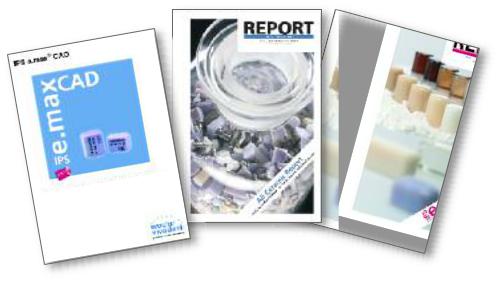
Further scientific data (e.g. strength, wear, biocompatibility) are contained in the “Scientific Documentation IPS e.max CAD”. The Documentation also provides a set of studies that describe the clinical performance of IPS e.max CAD.
This Scientific Documentation can be obtained from Ivoclar Vivadent.
For further information about all-ceramics and IPS e.max in general, please refer to the Ivoclar Vivadent Reports No. 16 and No. 17.
|
|
|
|
ion |
|
|
|
tat |
|
|
|
en |
|
|
|
cum |
|
|
|
|
tific Do |
|
|
|
en |
|
|
|
|
Sci |
|
|
|
|
6
Translucency Level
High
Translucency
Low
Translucency
Medium
Opacity
CR %
Block Concept
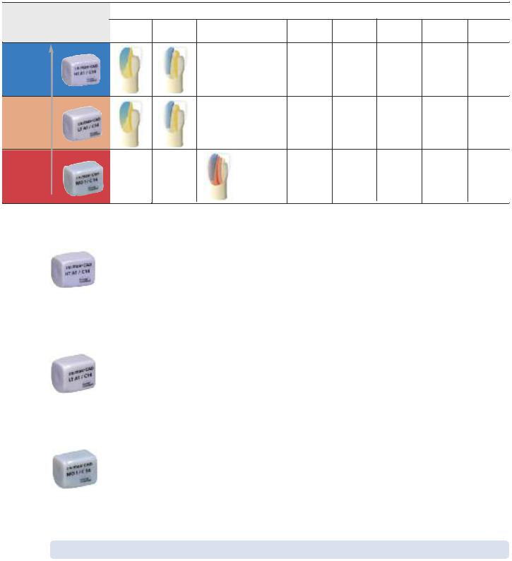
IPS e.max CAD is available in three levels of translucency (HT, LT,MO) and two sizes (I12, C14). From a processing point of view, basically all restorations can be fabricated from any block.
For reasons of esthetics, however, the following processing techniques and indications are recommended for the individual blocks (translucency levels):
Processing Technique |
|
|
Indications |
|
|
|||
Staining |
Cut-Back |
Layering |
Inlays |
Onlays |
Veneers |
Partial |
Anterior |
Posterior |
Technique |
Technique |
Technique |
|
|
|
Crowns |
Crowns |
Crowns |
|
|
|
|
|
|
|
|
|
|
|
|
|
|
|
|
|
|
|
|
|
|
|
|
|
|
|
|
|
|
|
|
|
|
|
* |
|
|
|
|
|
|
|
|
|
* up to the second premolar
IPS e.max CAD HT (High Translucency)
The HT Blocks are available in 16 A-D and 4 Bleach BL shades and 2 sizes (I 12, C 14). Given their translucency, they are ideally suitable for the fabrication of small restorations (e.g. inlays, onlays) by means of the staining technique, but they can also be used for the cut-back technique. Restorations made of HT blocks exhibit a true-to-nature chameleon effect and exceptional adaption to the remaining tooth structure. The stain and characterization firing, as well as glaze firing may be conducted with either IPS e.max CAD Crystall./Shades and Stains, Glaze, or IPS e.max Ceram Shades, Essences and Glaze.
IPS e.max CAD LT (Low Translucency)
The LT Blocks are available in 16 A-D and 4 Bleach BL shades and 2 sizes (I 12, C 14). Given their translucency, they are suitable for the cut-back and also the staining technique. Restorations made of LT blocks exhibit lifelike brightness value and chroma. This prevents the incorporated restorations from graying. The cut-back is supplemented with IPS e.max Ceram Incisal and/or Impulse and characterized using IPS e.max Ceram Essence and Shade.
IPS e.max CAD MO (Medium Opacity)
The MO Blocks are available in 5 group shades (MO 0- MO 4) in one size (C 14). Given their opacity, they are ideally suitable for the fabrication of frameworks on vital or slightly discoloured preparations. The anatomical shape is individually layered using ISP e.max Ceram. Finally, the Stain/Glaze
firing with IPS e.max Ceram is conducted.
The entire IPS e.max delivery program can be found at www.ivoclarvivadent.com!
7

CAD/CAM Partners
IPS e.max CAD can be processed with a system of the CAD/CAM partners. For questions regarding the different systems, please contact the respective cooperation partners.
Information is available from: |
Information is available from: |
Sirona Dental Systems GmbH |
KaVo Dental GmbH |
Fabrikstrasse 31 |
Bismarckring 39 |
64625 Bensheim |
88400 Biberach |
Germany |
Germany |
E-mail: contact@sirona.de |
E-mail:info@kavo.com |
www.sirona.com |
www.kavo-everest.com |
inLab® is a registered trademark of Sirona Dental Systems GmbH
Everest® is a registered trademark of KaVo Dental GmbH
Information is available from:
Institut Straumann AG
Peter Merian-Weg 12
4052 Basel
Switzerland
E-mail:info@straumann.com
www.straumann.com
8

IPS e.max® CAD
Clinical Working Steps, Fabrication Process
Working Step
Practice Laboratory
Preparation, Shade Determination
Impression Taking
Model Fabrication
CAD/CAM Process
Finishing, Check on Model
Staining |
Cut-Back |
Layering |
Technique |
Technique |
Technique |
Preparation for Cementation
Cementation
Ivoclar Vivadent Products
OptraGate,
IPS Natural Die Material
IPS Contrast Spray Labside
IPS e.max CAD
IPS e.max CAD Crystall./Shades, Stains IPS e.max CAD Crystall./Glaze
IPS CAD Crystallization Tray and Pins IPS e.max Ceram Layering Materials
IPS e.max Ceram Shades, Essences, Glaze
IPS Ceramic Etching Gel
Monobond Plus
OptraGate
OptraDam
iolink II, Variolink Veneer Multilink Automix
SpeedCEM
Vivaglass CEM bluephase
Check of Articulation/Occlusion |
OptraFine |
Recall |
Proxyt |
The range of products on offer may vary from country to country
Overview of the Clinical Working Steps, Fabrication Process
9

Shade Determination — Tooth Shade, Shade of the Prepared
Tooth
Optimum integration in the oral cavity of the patient is the prerequisite for a true-to-nature all-ceramic restoration. To achieve this, the following guidelines and notes must be observed by both the dentist and the laboratory.
The overall esthetic result of an all-ceramic restoration is influenced by the following factors:
•Shade of the preparation (natural preparation, core build-up, abutment, implant)
•Shade of the restoration (framework shade, veneer, characterization)
•Shade of the cementation material
The optical effect of the preparation shade must not be underestimated during the fabrication of highly esthetic restorations. For that reason, the shade of the preparation should be determined together with the desired tooth shade in order to select the suitable block. Especially with severely discoloured preparations or non-tooth-shaded build-ups, this is of utmost importance. Only if the dentist determines the shade of the preparation and its subsequent transmission to the laboratory may the desired esthetic result be achieved.
Preparation Shade |
Restoration Shade |
||
– Prepared natural tooth |
– Framework |
||
– |
Core build-up |
– |
Veneer |
– |
Implant, abutment |
– |
Characterization |
Desired Tooth Shade
Cementation Material
Responsibility of the Dental Office |
Responsibility of the Laboratory |
10
Shade determination of the natural tooth
After tooth cleaning, the tooth shade of the non-prepared tooth and/or the adjacent teeth is determined with the help of a shade guide. Individual characteristics have to be considered when determining the tooth shade. If a crown preparation is planned, for example, the cervical shade should also be determined. In order to achieve the best possible true-to-nature results, shade determination should be carried out in daylight. Furthermore, the patient should not wear clothes of intense colours and/or lipstick.
Die shade selection
In order to facilitate the reproduction of the desired tooth shade, the shade of the preparation is determined with the help of the IPS Natural Die Material shade guide. This enables the technician to fabricate a model die similar to the preparation of the patient, on the basis of
the correct shade and brightness values of the all-ceramic restorations may be selected.
Example of the preparation shade effect
Crown made of IPS e.max CAD HT B1 on different preparation shades.
Which block should be used?
The suitable block is selected on the basis of the following criteria:
1.Desired tooth shade
2.Preparation shade or abutment shade
3.Type of restoration
4.Restoration thickness and/or preparation depth
5.Processing technique (staining, cut-back or layering technique)
6.Cementation material
Please refer to the table on page 62 for block selection
Overview of the Clinical Working Steps, Fabrication Process
11
Preparation guidelines
Successful results can only be achieved with IPS e.max CAD if the guidelines and framework thicknesses are strictly
observed.
Basic preparation guidelines for all-ceramic restorations
–no angles or sharp edges
–shoulder preparation with rounded inner edges and/or chamfer preparation
–the indicated dimensions reflect the minimum thickness for IPS e.max CAD restorations
–the incisal edge of the preparation, particularly for anterior teeth, should be at least 1.0 mm (milling tool geometry) in order to permit optimum milling during CAD/CAM processing.
1.0
1.5
Veneer |
Anterior crown |
–If possible, the preparation should be located in the enamel.
–The incisal preparation margins should not be located in the area of static or dynamic enamel contact.
–Reduction in the cervical and/or labial area by 0.6 mm, and the incisal edge by 0.7 mm.
 1.0
1.0
1.0
1.2  1.0
1.0  1.2
1.2
1.5
–Reduce the anatomical shape and observe the stipulated minimum thickness. Prepare a shoulder with rounded inner edges or a deep chamfer. Width of the shoulder/chamfer at least 1.0 mm.
–Reduce the edge by approx. 1.5 mm.
–Reduce the labial and lingual area by approx. 1.2 mm.
–For conventional and/or self-adhesive cementation, the preparation must demonstrate retentive surfaces
12

Inlay |
Onlay |
1.06°
1.
100-120°
–Static and dynamic antagonist contacts must be taken into consideration.
–The preparation margins must not be located on centric antagonist contacts.
–A preparation depth of at least 1.0 mm and an isthmus width of at least 1.0 mm must be observed in the fissure area.
–Prepare the proximal box with slightly diverging walls and observe an angle of 100°-120° between the proximal cavity walls and the prospective proximal inlay surfaces. For inlays with pronounced convex cavity walls without adequate support by the proximal shoulder, marginal ridge contacts should be avoided.
–Round out internal edges in order to prevent stress concentration within the ceramic material.
–Do not prepare slice-cuts or feather edges.
6°
1.0
1.0
–Static and dynamic antagonist contacts must be taken into consideration.
–The preparation margins must not be located on centric antagonist contacts.
–A preparation depth of at least 1.0 mm and an isthmus width of at least 1.0 mm must be observed in the fissure area.
–Prepare the proximal box with slightly diverging walls and observe an angle of 100°-120° between the proximal cavity walls and the prospective proximal onlay surfaces. For onlays with pronounced convex cavity walls without adequate support by the proximal shoulder, marginal ridge contacts should be avoided.
–Round out internal edges in order to prevent stress concentration within the ceramic material.
–Do not prepare slice-cuts or feather edges.
–Provide at least 1.0 mm of reduction in the cusp areas.
|
|
|
|
Partial crown |
Posterior crown |
|
|
1.51.5
1.5
1.0
–Static and dynamic antagonist contacts must be taken into consideration.
–The preparation margins must not be located on centric antagonist contacts.
–Provide at least 1.5 mm of reduction in the cusp areas.
–Prepare a circular shoulder with rounded inner edges or a deep chamfer. Width of the shoulder/chamfer should be at least 1.0 mm.
1.51.5
1.5 |
1.5 |
1.0 1.0
1.0
6°
–Reduce the anatomical shape and observe the stipulated minimum thickness. Prepare a circular shoulder with rounded inner edges or a deep chamfer. Width of the shoulder/chamfer at least 1.0 mm.
–Reduce the incisal crown third by approx. 1.5 mm.
–Reduce the buccal or lingual area by approx. 1.5 mm.
–For conventional and/or self-adhesive cementation, the preparation must demonstrate retentive surfaces
Overview of the Clinical Working Steps, Fabrication Process
13

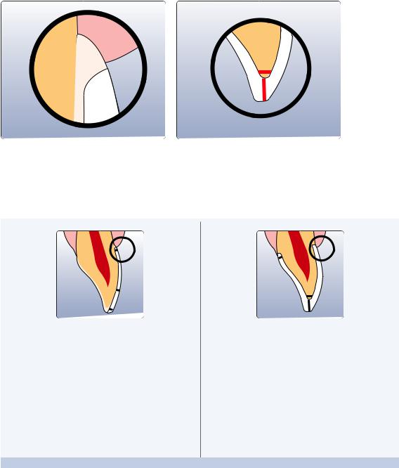
Model and Tooth Preparation
Fabricate a working model with removable segments as usual. The directions of the manufacturers of the different CAD/CAM systems regarding the plaster to be used must be observed.
Important for die preparation:
–Check the radius of the incisal/occlusal edge on the prepared die (maxilla and mandible).
–The prepared incisal edge should be at least as thick as the diameter of the bur used in the cavity during the CAD/CAM process.
–If the incisal edge of the prepared die is thinner than the diameter of the bur, the incisal edge has to be blocked out accordingly.
–Also observe the information provided by the manufacturer of the CAD/CAM system regarding the die geometry.
Inlay/onlay |
Veneer and anterior crown |
Posterior crown |
Anterior crown on a ZrO2 abutment |
|
(Straumann® Anatomic IPS e.max® Abutment) |
14

Layer thicknesses
The restoration design is key to the success of durable all-ceramic restorations. The more attention is given to the design, the better the final results and the clinical success will turn out to be. The following basic guidelines have to be observed:
–IPS e.max CAD is the high-strength component of your restoration and must, therefore, always make up at least 50% of the total layer thickness of the restoration.
–In large preparations and for veneered or partially veneered restorations, the excess available space must be compensated by the corresponding dimensions of the high-strength IPS e.max CAD component and not by the IPS e.max Ceram layering material.
–The design of the restoration generated by the software has to be individually adjusted, if necessary, in accordance with the clinical situation using the design tools.
–The areas that support and reinforce the shape and cusps of the restoration are constructed with the integrated design tools of the different types of software used.
–In partially veneered restorations, the transition between the layering material and IPS e.max CAD must not be located in the area of the functional contact points.
The following minimum thicknesses have to be observed to match the tooth shade of the shade guide and to
fulfil the requirements given from the preparation guidelines:
|
|
Veneer |
Inlay |
Onlay |
Partial |
|
Crowns |
|
|
|
|
|
|
|
crown |
|
|
|
|
|
|
|
|
|
|
Anterior |
Premolar |
Molar |
|
|
|
|
|
|
|
|
|
|
|
Minimum thickness |
circular |
0.6 |
1.0 |
1.0 |
1.5 |
1.2 |
1.5 |
1.5 |
|
isthmus width |
|||||||||
|
|
|
|
|
|
|
|||
IPS e.max CAD |
|
|
|
|
|
|
|
|
|
Staining technique |
incisal/occlusal |
0.7 |
1.0 |
1.0 |
1.5 |
1.5 |
1.5 |
1.5 |
|
|
isthmus width |
||||||||
|
|
|
|
|
|
|
|
||
Minimum thickness |
circular |
0.6 |
– |
– |
1.5 |
1.2 |
1.5 |
1.5 |
|
IPS e.max CAD |
|||||||||
|
|
|
|
|
|
|
|
||
Cut-back technique |
|
|
|
|
|
|
|
|
|
(after reduction) |
labial/occlusal |
0.4 |
– |
– |
1.3 |
0.4 |
1.0 |
1.3 |
|
|
circular |
– |
– |
– |
– |
0.8 |
0.8 |
– |
|
Minimum thickness |
|
|
|
|
|
|
|
|
|
IPS e.max CAD |
incisal/occlusal |
– |
– |
– |
– |
0.8 |
1.0 |
– |
|
|
|||||||||
Layering technique |
|
|
|
|
|
|
|
|
|
|
|
– |
– |
– |
– |
|
– |
||
|
design type |
supporting the tooth shape |
|||||||
|
|
|
|
|
|
|
|
|
|
dimensions in mm
For the cut-back and layering techniques the relationship of the layer thickness between IPS e.max CAD (framework) and IPS e.max Ceram (veneer) must also be observed:
Total layer thickness of the |
0.8 |
1.0 |
1.2 |
1.5 |
1.8 |
2.0 |
2.5 |
3.0 |
|
restoration in mm |
|||||||||
|
|
|
|
|
|
|
|
||
|
|
|
|
|
|
|
|
|
|
Minimum layer thickness of the |
0.4 |
0.5 |
0.6 |
0.8 |
1.0 |
1.1 |
1.3 |
1.6 |
|
framework ceramic mm |
|||||||||
|
|
|
|
|
|
|
|
||
|
|
|
|
|
|
|
|
|
|
Maximum layer thickness of the |
0.4 |
0.5 |
0.6 |
0.7 |
0.8 |
0.9 |
1.2 |
1.4 |
|
veneer with IPS e.max Ceram in mm |
|||||||||
|
|
|
|
|
|
|
|
||
|
|
|
|
|
|
|
|
|
Failure to observe the stipulated framework design criteria and minimum thicknesses may result in clinical failures, such as
cracks, delamination, and fracture of the restoration.
Overview of the Clinical Working Steps, Fabrication Process
15

Design guidelines for the restoration
IPS e.max CAD |
Veneering with IPS e.max Ceram |
Staining Technique |
|
– fully anatomical design |
|
Anterior tooth |
Premolar |
Molar |
Cut-back Technique
– partially reduced, cusp-supporting design
Anterior tooth |
Premolar |
Molar |
Layering Technique
– cusp-supporting design
Anterior tooth |
Premolar |
16

CAD/CAM processing
As densification of about 0.2% takes place in IPS e.max CAD during the crystallization process. This factor has been taken into account in the software. Consequently, the milled IPS e.max CAD restorations demonstrate precision of fit after crystallization. The fabrication steps are described in the directions for use and user manuals of the different CAD/CAM systems. The instructions of the manufacturers must be followed:
Information is available from: |
Information is available from: |
Sirona Dental Systems GmbH |
KaVo Dental GmbH |
Fabrikstrasse 31 |
Bismarckring 39 |
64625 Bensheim |
88400 Biberach |
Germany |
Germany |
E-mail: contact@sirona.de |
E-mail:info@kavo.com |
www.sirona.com |
www.kavo-everest.com |
inLab® is a registered trademark of Sirona Dental |
Everest® is a registered trademark of |
Systems GmbH |
KaVo Dental GmbH |
Information is available from:
Institut Straumann AG
Peter Merian-Weg 12
4052 Basel
Switzerland
E-mail:info@straumann.com
www.straumann.com
Overview of the Clinical Working Steps, Fabrication Process
17
IPS e.max® CAD –
Staining technique
In the staining technique, the milled full-contour restorations are completed by applying stains and glaze materials. Individualized characterizations and glaze can be applied either before or after Crystallization firing. Coordinated materials are available for the different procedures.
In this way, the use of translucent IPS e.max CAD blocks permit the fabrication of very esthetic restorations on only slightly or non-discoloured preparations with minimum effort.
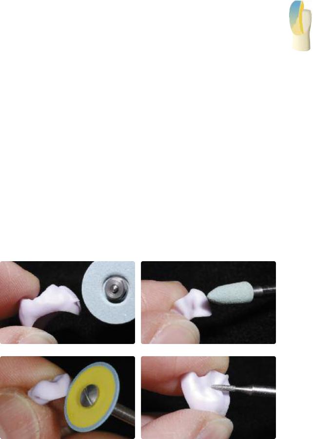
Finishing
It is of critical importance to use the correct grinding instruments for finishing and adjusting IPS e.max CAD. If unsuitable grinding instruments are used, chipping of the edges and local overheating may occur (please observe the Ivoclar Vivadent Flow Chart ”Recommended grinding tools for PS e.max glass-ceramics”.
Observe the following procedure for finishing IPS e.max CAD restorations:
–Carry out adjustments by grinding of IPS e.max CAD restorations while they are still in their pre-crystallized (blue) state, if possible.
–Only use suitable grinding instruments, low rpms and light pressure to prevent delamination and chipping at the edges in particular.
–Overheating of the glass-ceramic must be avoided.
–The restorations are tried in on the dies and carefully finished.
–Check proximal and occlusal contact points.
–Surface-grind the entire occlusal surface with a fine diamond to smooth out the surface structure created by the CAD/CAM procedure.
–Make sure that the minimum thicknesses are maintained even after the minor adjustments.
–Design surface textures.
–Always clean the restoration with ultrasound in a water bath or blast with the steam jet before crystallization.
–Make sure to thoroughly clean the restoration before further processing and to remove any residue of the milling additive of the CAD/CAM milling unit. Residue of the milling additive remaining on the surface may result in bonding problems and discolouration.
–Do not blast the restorations with Al2O3 or glass polishing beads.
Finish the restoration surface with suitable grinding instruments
Finish margins with suitable polishers |
Surface-grind the outer surface, particularly functional areas of the restoration with a fine |
|
diamond to smooth out the surface structure created by the CAD/CAM process |
18
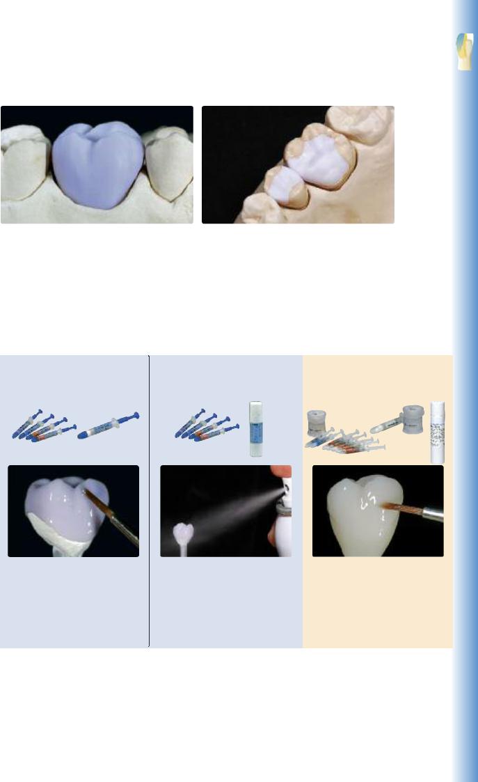
Staining Technique
IPS e.max CAD LT crown on the model |
IPS e.max CAD HT inlay/onlay on the model. |
Crystallization and Stain/Glaze Firing
Basically, fully anatomically milled restorations made of IPS e.max CAD can be completed in three different ways.
Option A: |
Option B: |
Option C: |
Crystallization and Glaze firing with |
Crystallization and Stain/Glaze firing |
Crystallization and separate Stain/Glaze |
IPS e.max CAD Crystall./Glaze paste |
with IPS e.max CAD Crystall./Glazespray |
firing with IPS e.max Ceram Shades, |
|
|
Essences and Glaze |
Characterization of the non-crystallized, |
Characterization of the non-crystallized, |
Characterization of the tooth-coloured |
blue restoration permits quick comple- |
blue restoration permits quick comple- |
restoration after crystallization. |
tion of the restoration with the |
tion of the restoration with the |
|
subsequent combination firing |
subsequent combination firing |
|
(Crystallization/Glaze HT/LT). |
(Crystallization/Glaze HT/LT). |
|
19
Option A:
Crystallization and Glaze firing in one step with IPS e.max CAD Crystall./Glaze paste
In this processing technique, crystallization and Glaze firing are performed in one step. Characterizations are applied using IPS e.max CAD Crystall./Shades and Stains.
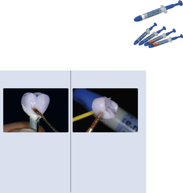
Preparation for Crystallization and Glaze firing
Depending on the type of restoration, they have to be placed on an IPS e.max CAD Crystallization P before the Stains and Glaze are applied. Smaller restorations (veneers, inlays, onlays) do not need to be entirely supported.
Either IPS Object Fix Putty or Flow are recommended to secure the restoration on the pin. The Putty demonstrates a denser consistency and thus higher stability. Given its lower viscosity, Flow is suitable for smaller restorations.
with
IPS e.max CAD Crystallization Pin
Partial Crown, Anterior Crown,
Posterior Crown
Use either IPS Object Fix Putty or Flow to secure the restoration on the pin.
without
IPS e.max CAD Crystallization Pin
Veneer,
Inlay, Onlay
To apply Glaze, Shades and Stains, secure the restoration
–with an OptraStick,
–with diamond tweezers, or
–directly on the die
Note: the restoration must be placed on a Crystallization pin with IPS Object Fix Putty or Flow before firing.
Observe the following procedure for partial crowns and crowns:
–Select the largest possible IPS e.max CAD Crystallization Pin (S, M, L) that best “fills” the inside of the restoration, but does not come into contact with the circular crown walls.
–Fill the inside of the restoration with IPS Object Fix Putty or Flow up to the restoration margin.
Immediately reseal the IPS Object Fix Putty/Flow syringe after extruding the material. Once removed from the aluminium bag, the syringe is ideally stored in a resealable plastic bag or a container with a humid atmosphere.
–Press the selected IPS e.max CAD Crystallization Pin deeply into the IPS Object Fix Putty or Flow material so that it is adequately secured.
–Smooth out displaced auxiliary firing paste using a plastic spatula so that the pin is securely in place and the restoration margins are optimally supported.
–Prevent contamination of the outer restoration surface. Clean off contamination with a brush dampened with water and dry.
20
Staining Technique
IPS Object Fix Flow and IPS Object Fix Putty |
Select the largest possible IPS e.max CAD Crystallization Pin |
Fill the inside of the crown with IPS Object Fix Putty or Flow.
Press the selected IPS e.max CAD Crystallization Pin deeply into the IPS Object Fix Putty or Flow material
Smooth out displaced IPS Object Fix Putty or Flow with a plastic spatula from the margin towards the spport pin so that the pin is secured in the paste and the crown wall is exactly supported
Clean off any possible residue adhering to the outer surface of the crown with a brush dampened with water and dry
21
 Loading...