


 Press
Press
 Abutment Solutions
|
|
|
|
|
|
|
|
|
|
|
|
|
|
|
|
|
|
ceramic |
|
||||
|
|
|
|||||
all |
|
||||||
|
|||||||
|
you |
need |
|
||||
all |
|
|
|
|
|||
|
|
|
|
|
|||
instructions for use

Table of Contents
application procedure
3 |
Product Information |
|
Material |
|
Uses |
|
Composition |
|
|
6 |
Fabrication of Hybrid Abutments and Hybrid Abutment Crowns |
|
Treatment/fabrication process |
|
Shade – tooth shade, preparation shade/abutment shade |
|
Model preparation |
|
Selecting a Ti base |
|
Layer thicknesses of the ceramic components |
|
Modeling |
|
Sprueing |
|
Investing |
|
Preheating |
|
Pressing |
|
Divesting |
|
Removing the reaction layer |
|
Finishing |
|
Stain and Characterization firing |
|
Glaze firing |
|
Crown on hybrid abutment |
32 |
Optional: Clinical Try-in |
|
Temporarily securing the pressed object on the Ti base |
|
Clinical try-in |
37 |
Permanent Cementation |
|
Pre-treatment of the Ti base |
|
Preparing the pressed object |
|
Cementation with Multilink Implant |
43 |
Seating and Aftercare |
|
Sterilization |
|
Intraoral preparation |
|
Seating the hybrid abutment and crown |
|
Seating the hybrid abutment crown |
|
Care notes – Implant Care |
50General Information
Frequently Asked Questions Material Selection Table Press and Firing Parameters Clinical Cases
2
IPS
e.max® Press Abutment Solutions
Product Information
Press ceramics have been synonymous with esthetics, accuracy of fit, shape and function for decades. The IPS e.max Press lithium disilicate (LS2) glass-ceramic additionally offers an outstanding strength of 400 MPa. The already extensive indication range from thin veneers (0.3 mm) and monolithic molar crowns to anterior and premolar bridges is now expanded to include hybrid abutment restorations.
With IPS e.max Press, you can fabricate such restorations in combination with a titanium base (Ti base). Two different approaches are available:
–Hybrid abutment and separate crown
–Hybrid abutment crown
Both solutions show outstanding function, efficiency and esthetics. The durable bond to the Ti base is achieved by means of the self-curing Multilink Implant luting composite.
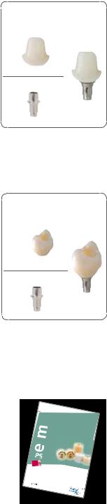
Hybrid abutment
The hybrid abutment is an individually pressed LS2 abutment which is luted to the Ti base. The shape, emergence profile and esthetic properties of this abutment can be ideally adjusted to the clinical situation.
Individual esthetics
Given the lifelike appearance of LS2 glass-ceramics, the esthetic possibilities are virtually limitless, particularly in the anterior region. Due to the individual characterization, a lifelike appearance is achieved near the root and the transition area to the crown. With the preparation margin of the crown located on the gingival level, the geometry of the hybrid abutments allows for an easy integration of the restoration. Excess cementation material is therefore easily removed.
Flexibility due to laboratory fabrication
Hybrid abutment
IPS e.max Press LS2
Abutment
Ti base
Base
The pressed LS2 abutment is extraorally luted to a Ti base with Multilink Implant, then screwed into place in the oral cavity and finally provided with a permanent IPS e.max crown. As the hybrid abutment is conveniently fabricated in the lab, the process is time-saving and flexible.
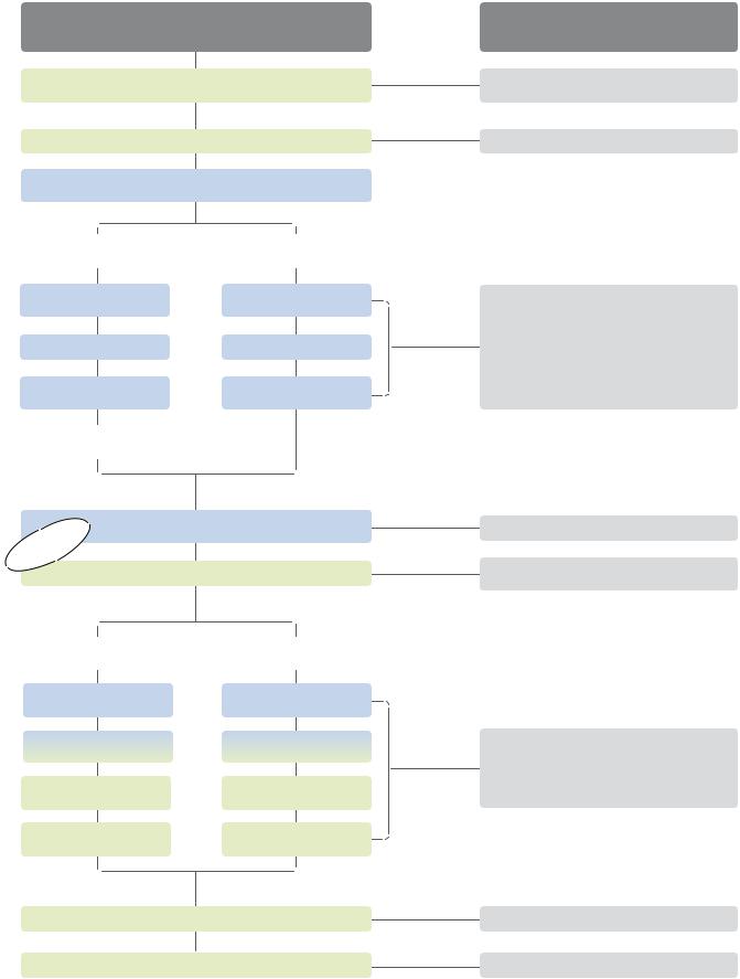
Hybrid abutment crown
Hybrid abutment crowns are characterized by combining abutment and monolithic crown in one piece. This is an efficient two-in-one solution made of lithium disilicate (LS2), which is directly luted to a Ti base.
Efficient fabrication due to two-in-one approach
LS2 glass-ceramics provide for strength, durability and efficiency, particularly in the posterior area. Moreover, the material offers well-known esthetic properties allowing restorations to be simply characterized with IPS e.max Ceram stains.
Luted extraorally, screwed in intraorally – for improved flexibility
The monolithically pressed hybrid abutment crown is reliably luted to the Ti base by means of Multilink Implant. Then, the restoration is screwed onto the implant – in one piece. Thus, the bothersome task of excess cement removal is a thing of the past. Subsequently, the screw access channel is sealed with a composite material (e.g. Tetric EvoCeram®). If required, the screw can be accessed at any time, which affords the dental team clincial flexibility.
New possibilities for economically efficient restorations
IPS e.max Press hybrid abutment crowns are a new, economically attractive alternative to conventional implant-supported restorations, particularly for the posterior area, where strength, durability and convenient clinical handling matter.
Hybrid abutment crown
IPS e.max Press LS2
Abutment
Ti base
Base
Note regarding the Instructions for Use:
The present Instructions for Use deal only with IPS e.max Press Abutment Solutions and represent a supplement to the existing IPS e.max Press Instructions for Use. The IPS e.max Press Instructions for Use contain more detailed descriptions of the material (e.g. ingot concept) and the entire indication range. In case you do not have the IPS e.max Press Instructions for Use, you can order them from your sales representative or simply download it from www.ivoclarvivadent.com.
s-VA-d.qxd 22.09.11  Press
Press
all ceramic all you need
I |
|
|
N S T R |
|
|
U C T I |
|
|
O N S |
F O R |
U S E |
|
3

Material |
Uses |
Press ceramic
IPS e.max Press are lithium disilicate glass-ceramic (LS2) ingots for the press technology. The industrial production process creates absolutely homogeneous ingots in dif-
ferent translucency levels. For IPS e.max Press Abutment Solutions, ingots from the exisitng range of products are used.
The ingots feature a strength of 400 MPa and are thus the pressed ceramic ingots with the highest strength. They are pressed in Ivoclar Vivadent press furnaces to produce objects with outstanding accuracy of fit. The pressed, tooth-coloured, highly esthetic restorations are completed with IPS e.max Ceram.
CTE (100–400°C) [10-6/K] |
10.2 |
CTE (100-500°C) [10-6/K] |
10.5 |
Flexural strength (biaxial) [MPa]* |
400 |
Fracture toughness [MPa m0.5] |
2.75 |
Modulus of elasticity [GPa] |
95 |
Vickers hardness [MPa] |
5800 |
|
|
Chem. solubility [µg/cm2]* |
40 |
Pressing temperature [°C] |
915–920 |
*according to ISO 6872 |
|
Ti base
For IPS e.max Press Abutment Solutions, customary Ti bases made of titanium or titanium alloys are used.
Please observe the instructions for use and processing of the manufacturer of the Ti bases used.
Indications
–Hybrid abutments for anterior and posterior single-tooth restorations
–Hybrid abutment crowns for anterior and posterior restorations
Contraindications
–Use of Ti bases which do not fulfil the geometry requirements.
–Failure to observe the requirements stipulated by the implant manufacturer for using the selected implant type (diameter and length of the implant must be approved for the respective position in the jaw by the implant manufacturer).
–Bruxism
–Failure to observe the permissible maximum and minimum ceramic wall thicknesses.
–All uses not stated as indications are contraindicated.
Important processing restrictions
Failure to observe the following restrictions may compromise the results achieved with IPS e.max Press:
–If hybrid abutment crowns are fabricated, the opening of the screw channel must not be located in the area of contact points and areas with masticatory function. If this is not possible, a hybrid abutment with a separate crown would be preferred.
–No extension units; only single-tooth restorations
–Layering with a veneering ceramic other than IPS e.max Ceram
–Pressing of two or more IPS e.max Press ingots in one investment ring
–Pressing of IPS e.max Press in the IPS Investment System 300 g
–Use of a luting composite other than Multilink® Implant to lute IPS e.max Press to the Ti base
–Temporary cementation of the crown on the hybrid abutment.
–Failure to observe the manufacturer's instructions regarding the processing of the Ti base.
Side effects
If the patient is known to be allergic to any of the components, IPS e.max Press Abutment Solutions should not be used.
4
Composition
IPS e.max Press ingots and accessories required in conjunction with IPS e.max Press Abutment Solutions consist of the following main components:
–IPS e.max Press ingots
Components: SiO2
Additional components: Li2O, K2O, MgO, ZnO, Al2O3, P2O5 and other oxides
–IPS Alox Plunger
Components: Al2O3
–IPS Alox Plunger Separator
Components: Boron nitride
–IPS e.max Press Invex Liquid
Components: Hydrofluoric acid and sulphuric acid in water
–IPS PressVEST Powder
Components: SiO2, MgO and NH4H2PO4
–IPS PressVEST Liquid
Components: Colloidal silicic acid in water
–IPS PressVEST Speed Powder
Components: SiO2, MgO and NH4H2PO4
–IPS PressVEST Speed Liquid
Components: Colloidal silicic acid in water
–IPS Object Fix Flow
Components: Oxides, water, thickening agent
–IPS Ceramic Etching Gel
Components: Hydrofluoric acid (approx. 5%)
–Virtual Extra Light Body Fast Set
Components: Addition-reaction silicone, vinyl polysiloxane, methylhydrogensiloxane, organoplatinic complex, silica
–Monobond Plus
Components: Alcohol solution of silane methacrylate, phosphoric acid methacrylate and sulphide methacrylate
–Multilink Implant
Components: Dimethacrylate, HEMA, barium glass, ytterbium trifluoride, spheroid mixed oxide
Warning
–Do not inhale ceramic dust during finishing – use exhaust air discharge and mouth protection.
–IPS Ceramic Etching Gel contains hydrofluoric acid. Contact with skin, eyes and clothing must be prevented at all costs, since the material is extremely toxic and corrosive. The etching gel is intended for professional use only and must not be applied intraorally (inside the mouth).
5
IPS
e.max® Press Abutment Solutions
Treatment/Fabrication Process
|
Working steps |
|
Ivoclar Vivadent |
|
|
|
All the products |
||
|
|
|
|
|
Implantation, healing phase, |
Cervitec Plus, Cervitec Liquid, |
|||
|
|
gingiva shaping |
|
Telio system |
Shade determination, impression-taking |
OptraGate, Virtual |
|||
|
Model fabrication, |
|
||
|
selection of Ti base |
|
||
Hybrid |
|
|
Hybrid |
|
abutment |
|
|
abutment crown |
|
Contouring |
|
|
Contouring |
IPS Investment Ring System 100g, 200g |
and Investing |
|
|
and investing |
IPS PressVEST, IPS PressVEST Speed |
|
|
|
|
IPS e.max Press |
Pressing |
|
|
Pressing |
Programat EP 3000, EP5000 |
|
|
IPS Alox Plunger |
||
|
|
|
|
|
|
|
|
|
IPS Alox Plunger Separator |
Characterization, glaze |
Characterization, glaze |
IPS e.max Ceram |
||
Optional: Polishing |
|
Programat P300, P500, P700 |
||
|
|
|
||
Crown made of |
|
|
|
|
IPS e.max Press |
|
|
|
|
|
Temporarily securing |
Optional |
pressed object – Ti base |
|
|
|
Clinical try-in |
Hybrid |
Hybrid |
abutment |
abutment crown |
Cementing |
Cementing |
pressed object – Ti base |
pressed object – Ti base |
Preparing for |
Preparing for |
intraoral cementation |
intraoral cementation |
Screwing in the hybrid abut- |
Screwing in the hybrid abut- |
ment intraorally |
ment crown intraorally |
Cementation |
Sealing |
IPS e.max Press crown |
the screw channel |
Virtual Extra Light Body Fast Set
OptraGate, Virtual Extra Light Body Fast Set,
Liquid Strip
IPS Ceramic Etching Gel, Monobond Plus,
Multilink Implant, Liquid Strip,
Tetric EvoCeram, bluephase
|
Checking the articulation/occlusion |
OptraFine, OptraPol, AstroPol |
||
|
|
|
Recall |
Implant Care |
|
|
|
|
|
Practice |
|
Laboratory |
|
|
|
6 |
The range of available products may vary from country to country. |
||

Shade – tooth shade, preparation shade/abutment shade
Optimum integration in the oral cavity of the patient is the prerequisite for a true-to-nature all-ceramic restoration. To achieve this, the following guidelines and notes must be observed by both the dentist and the laboratory.
With IPS e.max Press Abutment Solutions, you can imitate not only the clinical crown of a natural tooth, but also a part of the "root". By defining/determining the "root shade" you can adjust the shade of the IPS e.max Press Abutment Solution restoration accordingly. This allows you to achieve a highly esthetic implant-supported restoration which retains its lifelike appearance also in the case of gingiva recession.
Hybrid abutment and separate crown |
|
|
Restoration shade |
Shade luting material |
Shade hybrid abutment |
(pressed ceramic LS2, |
(crown on hybrid abutment) |
(Ti base, luting material, pressed |
characterization) |
|
ceramic LS2) |
 Hybrid abutment crown
Shade hybrid abumtent crown
(Ti base, luting material, pressed ceramic LS2, characterizations)
Please refer to the table on page 52 for the selection of the suitable IPS e.max Press ingot.
Application procedure – Fabrication Hybrid Abutment and Hybrid Abutment Crown
7
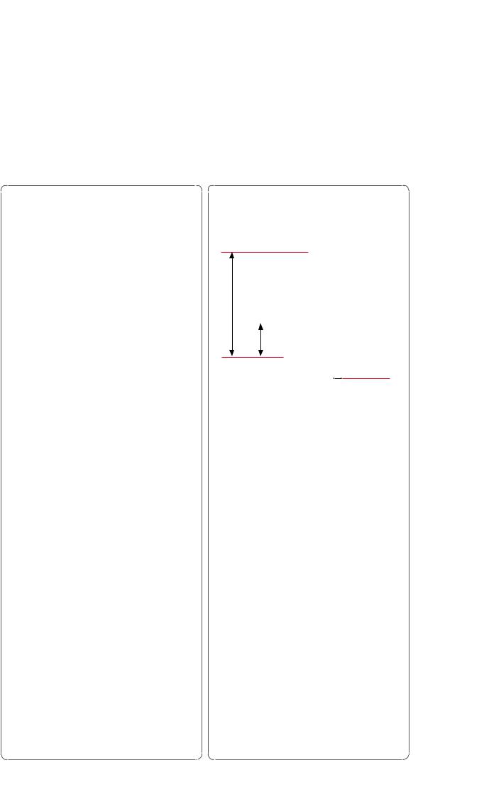
Model preparation
For the fabrication of an IPS e.max Press Abutment Solutions restoration, a model with gingiva mask is fabricated.
–Select the suitable model analog according to the implant system used.
–Fabricate a model with gingiva mask.
Prepared model with gingiva mask
Selecting a Ti base
The following paragraphs outline the selection criteria for a suitable Ti base. As a general rule, the instructions of the respective manufacturer regarding the use of the Ti base have to be observed.
–Only bases consisting of Ti or Ti alloys must be used.
–Select a Ti base with a size that matches the clinical situation and the chosen implant system. The geometry requirements must be observed.
–The rotation lock must be designed in such a way that stress concentrations on the pressed object are avoided.
–Ti bases with undercuts, e.g. retention grooves, are suitable to some extent.
–Check the available space for the pressed object taking the geometry of the Ti base into account on the model (e.g. silicone key).
–Observe the instructions of the manufacturer when modifying the Ti base.
|
Minimum dimensions |
Height HTi |
|
|
|
|
|
|
||
|
(luted area) |
|
|
|
|
|
|
|||
|
Height HTi |
Shoulder width STi |
|
|
|
|
|
|
|
|
|
|
|
|
|
|
|
|
|
||
|
(bonding surface) |
|
|
Marginal shoulder |
|
|
|
|
|
|
|
|
|
|
|
|
|
|
|
||
Ti base |
HTi min. 4.0 mm |
STi min. 0.6 mm |
|
width STi |
|
|
|
|
|
|
|
|
|
|
|
|
|||||
|
|
|
|
|
|
|
|
|||
8
Layer thicknesses of the ceramic components
Observing the geometry requirements of the pressed objects made of IPS e.max Press material is the key to success for a durable restoration. The more attention given to the design, the better the final results and the clinical success will turn out to be. The following basic guidelines have to be observed:
Hybrid abutment
Width abutment crown BAK
A |
|
H |
|
Height |
Wall thickness WA |
|
Marginal |
|
shoulder width SA |
–The marginal shoulder width SA must be at least 0.6 mm.
–Create an emergence profile with a right angle at the transition to the crown (see picture).
–The wall thickness WA must be at least 0.5 mm.
–The height HA must not exceed twice the height of the Ti base HTi.
–The hybrid abutment should be designed in a similar way as a prepared natural tooth:
– Circular epi-/supragingival shoulder with rounded inner edges or a chamfer.
– In order for the crown to be cemented to the hybrid abutment using a conventional/self- adhesive cementation protocol, retentive surfaces and a sufficient "preparation height" must be observed.
–The width BAK of the crown is limited to 6.0 mm from the axial height of contour to the screw
channel of the hybrid abutment.
Hybrid abutment crown
Width abutment crown BAK
Height HAK
Wall thickness WAK
Height
Ti base
Marginal shoulder width SA
–The marginal shoulder width SA must be at least 0.6 mm.
–The wall thickness WAK must be larger than 1.5 mm for the entire circumference.
–The opening of the screw channel must not be located in the contact point areas or areas with a masticatory function. If this is not possible, a hybrid abutment with a separate crown should be preferred.
–The width of the hybrid abutment crown BAK is limited to 6.0 mm from the axial height of contour to the screw channel.
–The height HAK must not exceed twice the height of
the Ti base by more than 2 mm.
Application procedure – Fabrication Hybrid Abutment and Hybrid Abutment Crown
9

Modeling
Fabrication of a resin coping
To prepare the wax-up, a resin coping is prepared if both hybrid abutments and hybrid abutment crowns are fabricated. Please observe the following procedure:
–Check the implant position and inclination with regard to the position of the screw channel.
–Screw the Ti base onto the model analog with the corresponding screw.
–Tip: Make sure that an additional model analog is available as this will facilitate some steps.
–Clean the Ti base with a steam cleaner.
–Insert a pin with the same diameter as the screw channel to "seal" and "extend" the screw channel.
–Do not apply die spacer.
–Isolate the Ti base and the pin with a thin application of separator. If too much separator is used, this might result in uneven areas on the inner aspect of the pressed object.
–In order to achieve a sound fit and to facilitate the subsequent wax-up, a coping is first fabricated on the Ti base with modelling resin. Design the coping in such a way that it can subsequently be completely covered with modelling wax. Please observe the instructions of the manufacturer regarding the processing of modelling resin.
–Remove the Ti base from the model.
–Eliminate possible over-contoured areas of the resin coping at the transition area to the Ti base by means of rubber polishers. Do not damage the Ti base.
–Remove the resin coping together with the pin from the Ti base.
–Loosen and remove the pin by rotating the resin coping.
–Screw the Ti base onto the model analog again.
–Place the resin coping back on the Ti base and check the fit and dimension (e.g. silicone key). If necessary, adjust the coping by means of rotary instruments.
Screw the Ti base onto the model analog with the corresponding screw.
–Insert a pin with the same diameter as the screw channel to "seal" and "extend"
the screw channel.
10

Isolate the Ti base and the pin with a thin application of separator.
Design the resin coping on the entire Ti base.
Apply the modelling resin to the Ti base in increments.
Remove the resin coping together with the pin from the Ti base.
Loosen and remove the pin by rotating the resin coping. |
Eliminate possible over-contoured areas of the resin coping at the transition area to |
|
the Ti base by means of rubber polishers. |
Place the resin coping back on the Ti base and check the fit and dimension (e.g. silicone key). If necessary, adjust the coping by means of rotary instruments. Design the coping in such a way that it can subsequently be covered with modelling wax.
Application procedure – Fabrication Hybrid Abutment and Hybrid Abutment Crown
11
Wax-up
Please observe the following notes with regard to modelling:
–Observe the stipulated layer thicknesses.
–Create an accurate model of the restoration, particularly at the transition area to the Ti base.
–Do not over-contour the margins, since this would require time-consuming and risky fitting procedures after pressing.
–Use an organic wax for modelling to ensure that it burns out without leaving residue in the investment ring.
Procedure for hybrid abutments
–Before creating the wax object, re-insert the isolated pin into the screw channel.
–Design the emergence profile by flooding the area between the gingiva mask and the resin coping with wax.
–Contour the hybrid abutment to a reduced tooth shape. The hybrid abutment should be designed in such a way that the required layer thicknesses are met in the crown that is fabricated. Check by means of the silicone key and in relation to the opposing dentition.
–Determine the crown margins in relation to the gingiva level.
–Design a chamfer on which the crown is subsequently seated.
–Remove the object together with the Ti base from the model and check the emergence profile. If necessary, make adjustments.
–Check the transition to the Ti base and remove excess wax.
–Check the required minimum thicknesses (page 9) prior to attaching the sprue.
Design the emergence profile by flooding the area between the gingiva mask and the resin coping with wax.
Design the hybrid abutment with a reduced tooth shape and determine the crown margin in relation to the gingiva level.
Check the dimensions by means of the silicone key and in relation to the opposing |
Remove the object together with the Ti base from the model and check the emergence |
dentition. |
profile. If necessary, make adjustments. Check the transition to the Ti base and |
|
thoroughly remove excess wax. |
12

Procedure for hybrid abutment crowns:
–If required, re-insert the isolated pin into the screw channel before creating the wax object.
–Design the emergence profile by flooding the area between the gingiva mask and the resin coping with wax.
–Design the abutment crown to full contour according to functional and esthetic criteria. Check in relation to the opposing dentition.
–Make sure to take a slightly reduced occlusal relief into consideration during the wax-up, since the application of the Stains and Glaze results in a slight increase in vertical dimensions.
–Remove the object together with the Ti base from the model and check the emergence profile. If necessary, make adjustments.
–Check the transition to the Ti base and remove possible excess wax.
–Check the required thicknesses (page 9) prior to attaching the sprues.
Design the emergence profile by flooding the area between the gingiva mask and the |
Design the abutment crown to full contour according to functional and esthetic |
resin coping with wax. If necessary, re-insert the pin prior to modelling. |
criteria. Check the object in relation to the opposing dentition. |
Application procedure – Fabrication Hybrid Abutment and Hybrid Abutment Crown
13

Sprueing
Please observe the following notes when attaching the sprues to the abutment or the abutment crown:
–Depending on the number and size of the objects to be invested, either the 100 g or 200 g IPS Investment Ring System is selected. Before sprueing, weigh the ring base and record the weight (seal the opening of the ring base with wax). Please note that the mixing ratio of the investment material is different for the various restoration types (e.g. inlays, crowns, abutments).
–Use a 2.5 mm wax wire for sprueing.
–For abutments, the sprue is attached to an axial surface.
–For abutment crowns, the sprue is attached to a cusp.
–Align the wax wire as parallel as possible to the screw channel in order to prevent the investment material from fracturing in the screw channel.
–The maximum length (object + sprue) of 16 mm must not be exceeded.
–Place the object on the investment ring base in such a way that the screw channel is parallel to the outer wall of the investment ring. As a result, the investment material can subsequently be filled evenly and in a controlled manner. The objects could be placed in a tilted position on the investment ring base, but this may lead to difficulties during investing (e.g. bubbles in the screw channel).
–Observe a distance of at least 10 mm between the object and the silicone ring.
–If only one object is invested and pressed in an EP500 furnace, a second short (blind) sprue must be placed. This ensures that the switch-off function of the furnace works properly at the end of the pressing procedure.
ø 2.5 mm |
ø 2.5 mm |
Attach the sprue to a circular area of the abutment model and as parallel as possible to the screw channel. Use a 2.5 mm wax wire.
Attach the sprue to an oral cusp of the abutment crown and as parallel as possible to the screw channel. Use a 2.5 mm wax wire.
Place the object on the investment ring base in such a way that the screw channel is parallel to the outer wall of the investment ring. As a result, the investment material can subsequently be filled evenly and in a controlled manner.
Furthermore, this reduces the risk of the investment material breaking in the screw channel while the ceramic material is pressed.
14

Investing
Investing is carried out with either IPS PressVEST or IPS PressVEST Speed. The corresponding IPS Silicone Ring with the matching ring gauge is used for investment.
Determine the weight of the object before investing.
–Position the wax objects on the ring base and attach them with wax and weigh.
–The difference between the empty and the loaded ring base is the definitive wax weight.
|
Small Ingot |
Large Ingot (L) |
Wax weight |
up to max. 0.75 g |
up to max. 2 g |
Investment Ring System |
100 g and 200 g |
only 200 g |
Please refer to the Instructions for Use of the corresponding investment material regarding the detailed processing parameters. The following basic procedure is recommended:
–Do not use a debubblizer on the wax objects.
–Carefully place the IPS Silicone Ring on the ring base without damaging the objects. The silicone ring must sit flush on the ring base.
–The processing temperature of the investment material is 18– max. 23 °C / 64 °F – max. 73 °F. Higher or lower processing temperatures substantially affect the setting behaviour.
–Mix the investment material. Note: The investment material contains quartz powder. Therefore, avoid the inhalation of dust.
–Important: Pour the investment material slowly into the investment ring, so that the material continuously fills the screw channel. If the material does not sufficiently fill the screw channel, use an instrument to carefully apply additional investment material to the screw channel from the top.
–Carefully fill the investment ring with investment material up to the marking on the silicone ring and position the ring gauge with a hinged movement.
–Allow the investment ring to set without manipulating it.
–To prevent crystallization of the IPS PressVEST investment material, the invested ring must be processed within 24 hours.
–If IPS PressVest Speed is used, make sure that the investment ring is placed in the preheating furnace after a setting time of at least 30 and maximum 45 minutes.
Investment material: Liquid concentration and quantity
|
IPS PressVEST |
IPS PressVEST Speed |
|||
Indication |
100 g Investment Ring |
200 g Investment Ring |
100 g Investment Ring |
200 g Investment Ring |
|
Liquid : dist. water |
Liquid : dist. water |
Liquid : dist. water |
Liquid : dist. water |
||
IPS e.max Press |
|
|
|
|
|
Hybrid abutment |
16 ml : 6 ml |
32 ml : 12 ml |
20 ml : 7 ml |
40 ml : 14 ml |
|
Hybrid abutment crown |
|||||
|
|
|
|
||
Mixing time |
60 seconds |
2.5 minutes |
|||
(under vacuum at approx. 350 rpm) |
If a high-speed mixer is used, the mixing time under |
||||
|
|
vacuum has to be reduced. |
|||
|
|
|
|||
|
|
|
|
|
|
Liquid concentration: The data contained in the table are approximative values. Depending on the geometry of the Ti base and the materials used for the wax-up, these values may be individually changed. However, the concentrated Liquid content must not be lower than 50% in relation to distilled water.
Important: The total quantity of liquid (Liquid + dist. water) must not be altered.
Application procedure – Fabrication Hybrid Abutment and Hybrid Abutment Crown
15

Correctly sprued abutment (left) and abutment crown (right). The screw channel is in a vertical position and parallel with the wall of the investment ring.
Pour the investment material slowly into the investment ring, so that the material can continuously fill the screw channel.
Continue to carefully fill the investment ring up to the marking and position the ring gauge with a hinged movement.
16

Preheating
After the stipulated setting time of the respective investment material (IPS PressVEST or IPS PressVEST Speed), the investment ring is prepared for preheating as follows:
–Remove the ring gauge with a turning movement.
–Carefully push the investment ring out of the IPS Silicone Ring.
–Remove the ring base with a turning movement.
–Remove rough spots on the bottom surface of the investment ring with a plaster knife. Check the 90° angle. Investment material residue must not enter the sprues. Blow into the sprues if necessary.
–If several investment rings are preheated together, mark them accordingly.
|
IPS PressVEST |
IPS PressVEST Speed |
|
Setting time |
min. 60 min, max. 24 hrs |
min. 30 min, max. 45 min |
|
Temperature of the preheating furnace |
Room temperature |
850 °C / 1562 °F; switch on the |
|
when placing the investment ring |
preheating furnace in time. |
||
|
|||
Position of the investment ring in the |
Towards the rear wall, tipped with the |
Towards the rear wall, tipped with the |
|
preheating furnace |
opening facing down |
opening facing down |
|
Final temperature for preheating the |
850 °C / 1562 °F |
850 °C / 1562 °F |
|
investment ring |
|||
|
|
||
Holding time of the investment ring at |
min. 60 min |
100 g investment ring – min. 45 min |
|
final temperature |
200 g investment ring – min. 60 min |
||
|
|||
IPS e.max Press ingots |
no preheating |
no preheating |
|
IPS Alox Plunger |
no preheating |
no preheating |
|
Important |
|
If several Speed investments are to be |
|
|
|||
|
|
conducted, they should be invested |
|
|
|
consecutively and placed into the pre- |
|
|
|
heating furnace at an interval of |
|
|
|
approx. 20 minutes. Make sure that |
|
|
|
the furnace temperature does not |
|
|
|
drop too much when placing the |
|
|
|
investment rings into the preheating |
|
|
|
furnace. The stipulated holding time |
|
|
|
counts from the point when the pre- |
|
|
|
heating temperature has been reached |
|
|
|
again. |
|
|
|
|
Towards the rear wall, tipped with the opening facing down |
Do not preheat the IPS e.max Press ingot and Alox Plunger. |
In order to ensure smooth working procedures in the laboratory on a daily basis, impeccable functioning of the infrastructure, particularly the preheating furnaces, is essential. This includes their maintenance, cleaning with a vacuum cleaner in a cool state as well as regular checks of the temperature controls and heating elements, etc., by the manufacturer.
Application procedure – Fabrication Hybrid Abutment and Hybrid Abutment Crown
17
 Loading...